EP1066956A2 - Schichtverbund mit geschweisster Metalleinlage - Google Patents
Schichtverbund mit geschweisster Metalleinlage Download PDFInfo
- Publication number
- EP1066956A2 EP1066956A2 EP00113982A EP00113982A EP1066956A2 EP 1066956 A2 EP1066956 A2 EP 1066956A2 EP 00113982 A EP00113982 A EP 00113982A EP 00113982 A EP00113982 A EP 00113982A EP 1066956 A2 EP1066956 A2 EP 1066956A2
- Authority
- EP
- European Patent Office
- Prior art keywords
- metal
- overlap area
- layer composite
- reinforced layer
- metal foils
- Prior art date
- Legal status (The legal status is an assumption and is not a legal conclusion. Google has not performed a legal analysis and makes no representation as to the accuracy of the status listed.)
- Granted
Links
Images



Classifications
-
- B—PERFORMING OPERATIONS; TRANSPORTING
- B23—MACHINE TOOLS; METAL-WORKING NOT OTHERWISE PROVIDED FOR
- B23K—SOLDERING OR UNSOLDERING; WELDING; CLADDING OR PLATING BY SOLDERING OR WELDING; CUTTING BY APPLYING HEAT LOCALLY, e.g. FLAME CUTTING; WORKING BY LASER BEAM
- B23K11/00—Resistance welding; Severing by resistance heating
- B23K11/02—Pressure butt welding
-
- B—PERFORMING OPERATIONS; TRANSPORTING
- B32—LAYERED PRODUCTS
- B32B—LAYERED PRODUCTS, i.e. PRODUCTS BUILT-UP OF STRATA OF FLAT OR NON-FLAT, e.g. CELLULAR OR HONEYCOMB, FORM
- B32B15/00—Layered products comprising a layer of metal
- B32B15/14—Layered products comprising a layer of metal next to a fibrous or filamentary layer
-
- B—PERFORMING OPERATIONS; TRANSPORTING
- B23—MACHINE TOOLS; METAL-WORKING NOT OTHERWISE PROVIDED FOR
- B23K—SOLDERING OR UNSOLDERING; WELDING; CLADDING OR PLATING BY SOLDERING OR WELDING; CUTTING BY APPLYING HEAT LOCALLY, e.g. FLAME CUTTING; WORKING BY LASER BEAM
- B23K11/00—Resistance welding; Severing by resistance heating
- B23K11/16—Resistance welding; Severing by resistance heating taking account of the properties of the material to be welded
-
- B—PERFORMING OPERATIONS; TRANSPORTING
- B23—MACHINE TOOLS; METAL-WORKING NOT OTHERWISE PROVIDED FOR
- B23K—SOLDERING OR UNSOLDERING; WELDING; CLADDING OR PLATING BY SOLDERING OR WELDING; CUTTING BY APPLYING HEAT LOCALLY, e.g. FLAME CUTTING; WORKING BY LASER BEAM
- B23K11/00—Resistance welding; Severing by resistance heating
- B23K11/16—Resistance welding; Severing by resistance heating taking account of the properties of the material to be welded
- B23K11/163—Welding of coated materials
-
- B—PERFORMING OPERATIONS; TRANSPORTING
- B23—MACHINE TOOLS; METAL-WORKING NOT OTHERWISE PROVIDED FOR
- B23K—SOLDERING OR UNSOLDERING; WELDING; CLADDING OR PLATING BY SOLDERING OR WELDING; CUTTING BY APPLYING HEAT LOCALLY, e.g. FLAME CUTTING; WORKING BY LASER BEAM
- B23K20/00—Non-electric welding by applying impact or other pressure, with or without the application of heat, e.g. cladding or plating
- B23K20/22—Non-electric welding by applying impact or other pressure, with or without the application of heat, e.g. cladding or plating taking account of the properties of the materials to be welded
-
- B—PERFORMING OPERATIONS; TRANSPORTING
- B23—MACHINE TOOLS; METAL-WORKING NOT OTHERWISE PROVIDED FOR
- B23K—SOLDERING OR UNSOLDERING; WELDING; CLADDING OR PLATING BY SOLDERING OR WELDING; CUTTING BY APPLYING HEAT LOCALLY, e.g. FLAME CUTTING; WORKING BY LASER BEAM
- B23K33/00—Specially-profiled edge portions of workpieces for making soldering or welding connections; Filling the seams formed thereby
-
- B—PERFORMING OPERATIONS; TRANSPORTING
- B32—LAYERED PRODUCTS
- B32B—LAYERED PRODUCTS, i.e. PRODUCTS BUILT-UP OF STRATA OF FLAT OR NON-FLAT, e.g. CELLULAR OR HONEYCOMB, FORM
- B32B15/00—Layered products comprising a layer of metal
- B32B15/04—Layered products comprising a layer of metal comprising metal as the main or only constituent of a layer, which is next to another layer of the same or of a different material
-
- B—PERFORMING OPERATIONS; TRANSPORTING
- B32—LAYERED PRODUCTS
- B32B—LAYERED PRODUCTS, i.e. PRODUCTS BUILT-UP OF STRATA OF FLAT OR NON-FLAT, e.g. CELLULAR OR HONEYCOMB, FORM
- B32B15/00—Layered products comprising a layer of metal
- B32B15/04—Layered products comprising a layer of metal comprising metal as the main or only constituent of a layer, which is next to another layer of the same or of a different material
- B32B15/08—Layered products comprising a layer of metal comprising metal as the main or only constituent of a layer, which is next to another layer of the same or of a different material of synthetic resin
-
- B—PERFORMING OPERATIONS; TRANSPORTING
- B32—LAYERED PRODUCTS
- B32B—LAYERED PRODUCTS, i.e. PRODUCTS BUILT-UP OF STRATA OF FLAT OR NON-FLAT, e.g. CELLULAR OR HONEYCOMB, FORM
- B32B3/00—Layered products comprising a layer with external or internal discontinuities or unevennesses, or a layer of non-planar shape; Layered products comprising a layer having particular features of form
- B32B3/02—Layered products comprising a layer with external or internal discontinuities or unevennesses, or a layer of non-planar shape; Layered products comprising a layer having particular features of form characterised by features of form at particular places, e.g. in edge regions
- B32B3/04—Layered products comprising a layer with external or internal discontinuities or unevennesses, or a layer of non-planar shape; Layered products comprising a layer having particular features of form characterised by features of form at particular places, e.g. in edge regions characterised by at least one layer folded at the edge, e.g. over another layer ; characterised by at least one layer enveloping or enclosing a material
-
- F—MECHANICAL ENGINEERING; LIGHTING; HEATING; WEAPONS; BLASTING
- F16—ENGINEERING ELEMENTS AND UNITS; GENERAL MEASURES FOR PRODUCING AND MAINTAINING EFFECTIVE FUNCTIONING OF MACHINES OR INSTALLATIONS; THERMAL INSULATION IN GENERAL
- F16J—PISTONS; CYLINDERS; SEALINGS
- F16J15/00—Sealings
- F16J15/02—Sealings between relatively-stationary surfaces
- F16J15/06—Sealings between relatively-stationary surfaces with solid packing compressed between sealing surfaces
- F16J15/10—Sealings between relatively-stationary surfaces with solid packing compressed between sealing surfaces with non-metallic packing
- F16J15/12—Sealings between relatively-stationary surfaces with solid packing compressed between sealing surfaces with non-metallic packing with metal reinforcement or covering
- F16J15/121—Sealings between relatively-stationary surfaces with solid packing compressed between sealing surfaces with non-metallic packing with metal reinforcement or covering with metal reinforcement
- F16J15/122—Sealings between relatively-stationary surfaces with solid packing compressed between sealing surfaces with non-metallic packing with metal reinforcement or covering with metal reinforcement generally parallel to the surfaces
-
- B—PERFORMING OPERATIONS; TRANSPORTING
- B32—LAYERED PRODUCTS
- B32B—LAYERED PRODUCTS, i.e. PRODUCTS BUILT-UP OF STRATA OF FLAT OR NON-FLAT, e.g. CELLULAR OR HONEYCOMB, FORM
- B32B2581/00—Seals; Sealing equipment; Gaskets
-
- Y—GENERAL TAGGING OF NEW TECHNOLOGICAL DEVELOPMENTS; GENERAL TAGGING OF CROSS-SECTIONAL TECHNOLOGIES SPANNING OVER SEVERAL SECTIONS OF THE IPC; TECHNICAL SUBJECTS COVERED BY FORMER USPC CROSS-REFERENCE ART COLLECTIONS [XRACs] AND DIGESTS
- Y10—TECHNICAL SUBJECTS COVERED BY FORMER USPC
- Y10T—TECHNICAL SUBJECTS COVERED BY FORMER US CLASSIFICATION
- Y10T428/00—Stock material or miscellaneous articles
- Y10T428/12—All metal or with adjacent metals
- Y10T428/12347—Plural layers discontinuously bonded [e.g., spot-weld, mechanical fastener, etc.]
-
- Y—GENERAL TAGGING OF NEW TECHNOLOGICAL DEVELOPMENTS; GENERAL TAGGING OF CROSS-SECTIONAL TECHNOLOGIES SPANNING OVER SEVERAL SECTIONS OF THE IPC; TECHNICAL SUBJECTS COVERED BY FORMER USPC CROSS-REFERENCE ART COLLECTIONS [XRACs] AND DIGESTS
- Y10—TECHNICAL SUBJECTS COVERED BY FORMER USPC
- Y10T—TECHNICAL SUBJECTS COVERED BY FORMER US CLASSIFICATION
- Y10T428/00—Stock material or miscellaneous articles
- Y10T428/12—All metal or with adjacent metals
- Y10T428/12431—Foil or filament smaller than 6 mils
- Y10T428/12438—Composite
-
- Y—GENERAL TAGGING OF NEW TECHNOLOGICAL DEVELOPMENTS; GENERAL TAGGING OF CROSS-SECTIONAL TECHNOLOGIES SPANNING OVER SEVERAL SECTIONS OF THE IPC; TECHNICAL SUBJECTS COVERED BY FORMER USPC CROSS-REFERENCE ART COLLECTIONS [XRACs] AND DIGESTS
- Y10—TECHNICAL SUBJECTS COVERED BY FORMER USPC
- Y10T—TECHNICAL SUBJECTS COVERED BY FORMER US CLASSIFICATION
- Y10T428/00—Stock material or miscellaneous articles
- Y10T428/12—All metal or with adjacent metals
- Y10T428/12493—Composite; i.e., plural, adjacent, spatially distinct metal components [e.g., layers, joint, etc.]
- Y10T428/12535—Composite; i.e., plural, adjacent, spatially distinct metal components [e.g., layers, joint, etc.] with additional, spatially distinct nonmetal component
- Y10T428/12556—Organic component
- Y10T428/12569—Synthetic resin
Definitions
- the present invention relates to metal reinforced Layer composites based on one or more Soft materials, especially sealing plates, and a Process for their production.
- the invention metal-reinforced layer composites have at least one Metal insert, the metal insert consisting of at least two at least partially overlapping metal foils exists, which are connected to each other in the overlap area are.
- the invention enables composite panels with large To produce dimensions that are the highest as sealing plates meet technical requirements. From these Sealing plates become seals, especially flat seals in a ring shape, as shown in Figure 9, made by punching.
- Layer composites based on one or more Soft materials are used to improve mechanical Strength often reinforced with thin metal foils.
- Thermoplastics, especially based on PTFE, and elastomers, by inorganic or organic fibers such as e.g. Aramid, carbon, ceramic and metal fibers reinforced can be or their compressive strength through fillers such as e.g. Silicon dioxide, aluminum oxide, carbon, graphite in Powder form can be increased.
- softeners inorganic and pressure-resistant materials such as especially mica and graphite are used.
- special Graphite variants are also made from expanded graphite manufactured films and laminates, in the following together Called graphite foils.
- Corresponding layer composites are e.g.
- skewers can also be used be applied, the skewers of which go to one or both Pages can extend.
- the metal foils are commercial depending on the material and Film thickness only available up to a limited web width.
- metal-reinforced laminates in realized on an industrial scale by using metal foil webs overlaps at their lateral ends and either by gluing, by mechanical gearing or by welding such as resistance roller seam welding connects with each other. Since those in the strata for the metal inlays mostly used a metal foil have a small thickness, e.g. 50 ⁇ m or 100 ⁇ m to a simple punching out of seals from the layered composites butt welding can be made possible of metal foils in the context of technical Usually do not realize production conditions.
- a butt welding method and apparatus abutting plates is from DE 195 29 542 A1 known. This process is based on the fact that the welded First, sheet in your peripheral area overlap, then the overlapping end zones of the edge areas with aligned cutting edges be cut off, then the cut surfaces blunt brought together and finally the cut surfaces are welded together using a laser beam. Through this chronological succession of process steps can be particularly in the case of long webs that move will not be guaranteed that the cut edges perpendicular to the direction of movement of the webs still in the same position if they are the location of the Achieve welding as they are at the moment of welding Cutting.
- connection is made by introducing an adhesive such as epoxy resin between the overlapping ends of the film, which hardens.
- the adhesive is usually applied to at least one of the metal foils to be connected over the entire overlap area.
- the adhesive bonding of the metal foils has the disadvantage that seals which have been produced from layered composites which have metal inserts connected in this way can only be used in a narrowly limited temperature range. This is due to the fact that the adhesive softens and / or is partially thermally degraded at higher temperatures.
- the metal foils in the seals can more easily shear against one another at their bonded connection points under mechanical stress, such as tensile forces in the direction of the metal foils and compressive forces perpendicular to the metal inserts, thereby reducing the mechanical stability of the seals. Due to thermal degradation of the adhesive, only porous, leaky pyrolyzed residues of the adhesive remain in the overlap area between the bonded metal foil ends.
- seals that have metal inserts with metal foils glued to one another are limited to media that do not attack the adhesive, since otherwise the attack of the medium on the adhesive in turn can cause the metal foils to shear off due to mechanical stresses and thus mechanical stability the seals are reduced and, on the other hand, leakage channels can form in the adhesive similar to high temperatures due to the degradation of the adhesive by the aggressive medium to be sealed, so that the sealing effect of the seal is no longer guaranteed. It is therefore necessary for the universal use of seals which are produced from layered composites which have metal inserts connected from at least two metal foils that the metal foils of these metal inserts are connected without the introduction of further media such as adhesives into the seals.
- the ends of the metal foils are guided overlapping and connected to one another by heating by the metal foils lying one above the other in the overlap region.
- the weld seam that is to say the area in which the metal foils are connected by the heating, runs in the longitudinal direction of the overlap area.
- the width of the overlap area is usually significantly larger than the width of the related weld.
- resistance welding in the form of spot welding (discontinuous welding) and roller seam welding (continuous welding) is used.
- spot welding the welding electrodes are placed in the middle of the overlap area on the two metal foils to be welded and then the foils are melted and connected by a current pulse.
- roller seam welding disc-shaped electrode rollers are used, through which the overlapping ends of the foil webs are drawn. This creates a linear weld that runs in the middle of the overlap area.
- the position of the welding points or weld seam is chosen in the middle in order to guarantee that the welding electrodes or welding electrode rollers contact the two metal foils over their entire width during welding, since otherwise a too high area current can lead to the metal foils burning away at the welding point.
- laser beam welding can also be used to connect the metal foils in their overlap area. The energy of the laser beam is absorbed by the metal foils in the form of heat, as a result of which the metal foils fuse.
- the laser beam should be positioned in the middle of the overlap area and the two overlapping metal foil webs should be moved relative to the fixed laser. A linear, integral weld seam can thus be produced in the overlap area of the foils.
- the object of the present invention is to provide high quality metal reinforced laminates based on one or more soft materials at least one metal insert consisting of at least two interconnected metal foils consists of which Seals can be made that are the same Have properties like seals that come from corresponding Layered were made that only included one-piece metal inserts, and the deployment of processes for the production of corresponding Laminated with at least two metal foils connected metal inserts.
- high quality stands for for a high Temperature and media resistance as well as high mechanical stability. Comparison of the properties of corresponding metal-reinforced layer compounds with and without metal inserts by connecting at least two metal foils have been made, but refer to all on the leakage rates of seals that come from the Layered can be produced.
- Another object of the present invention is Provision of large format and inexpensive metal-reinforced layer composites based on one or several soft materials, especially sealing plates, which have the same properties as metal reinforced Layer composites that were previously conventional one-piece metal inserts were produced.
- Seals are supposed to be bonded from the large format layers are produced that have the same leakage rates have like seals that were previously made from conventional Layered were produced.
- the large-format layer composites metal inlays include that by connecting at least two metal foils were produced.
- Another object of the invention was sealing plates to provide from which one-piece Seals can be punched out, their dimensions go beyond what is currently available and still the properties according to the previously available have one-piece seals of smaller dimensions, especially in relation to the leakage rates of the seals. Sealing plates and their dimensions are required for this go beyond the dimensions available so far without thereby the properties of the from the sealing plates stamped seals are adversely affected.
- a metal-reinforced layer composite on the Basis of one or more soft materials the least has a metal insert and at least one of these metal inserts by connecting at least two at least partially overlapping metal foils at least one weld seam was made available, in which at each of the existing in the layer network two welds connecting two metal foils none and / or none in the longitudinal extent of the overlap area continuous leakage channels are available.
- a method for producing a metal-reinforced layer composite according to the invention the basis of at least one soft material that on the following technique to connect the at least partially overlapping metal foils of the metal inlays is based on: welding at least once of the films along the longitudinal direction of the overlap area takes place in such a way that in the overlap area none between the foils to be welded and / or none in the longitudinal extent of the overlap area continuous open areas.
- the weld seam is in the overlap area to lead the existence or at least the Existence of continuous leakage channels in the overlap area is excluded. With a linear weld according to the prior art, this is not guaranteed. There are no welds here Metal foil protrusions in the overlap area, which are in Extend the longitudinal direction of the overlap area.
- the welding of the metal foils can so that the length of the non-continuous Leakage channels on the weld seams along the longitudinal extent of the overlap area the maximum length of Does not exceed 25 mm.
- the maximum is preferably Length of the non-continuous leakage channels at the weld seams along the length of the overlap area between 0.5 mm and 5 mm, particularly preferred between 1 and 2 mm.
- the metal-reinforced layer composites according to the invention one or more soft materials can also be added their flat sides facing outwards covered with a gas-tight film made of organic polymer and be connected.
- At least one of the weld seams can be one Have course that in at least one point P a Direction component perpendicular to the longitudinal extension of the Has overlap area of the metal foils.
- Course of the weld perpendicular to the longitudinal extent of the Overlap area is created by the fact that the Welding is done along a line that is a directional component perpendicular to the longitudinal extent of the overlap area which has metal foils.
- the line along which the welding takes place continues also called welding line, is in the sense of the present Invention the line along which the welding equipment is guided relative to the metal foils, the Move the welding machine and / or the metal foils in the room.
- the welding of the at least partially overlapping Metal foils can be continuous, but also with interruptions or pulsed.
- continuous Welding shop can use the metal foils with welds connected without interruption along the Overlap area.
- the Weld with the line along which the welding done, completely together.
- Partially or discontinuously Welding shop have the welds at least one break in the weld along the Weld line and thus along the longitudinal extent of the Overlap area.
- this also counts the pulsed welding, in which only at certain time intervals a welding process takes place while the Welding equipment travels along the welding line.
- the welding line along which the welding of the metal foils takes place in particular a periodic Course along the longitudinal extent of the overlap area of the metal foils.
- the Course of the weld seam for example sinusoidal, be meandering, zigzag or stair-shaped.
- the period length of the weld seam is also used here the maximum length of the open areas between metal foils in their overlap area towards the Longitudinal direction of the overlap area determined, i.e. the maximum length of the non-continuous leakage channels along the weld.
- Seals composed of the layer according to the invention be manufactured must have a seal width D, which is greater than the period length of the weld, in order no open leakage channels.
- the period length usually chosen smaller than 25 mm.
- Prefers is used for welding with a periodic course
- Weld seam a period length between 0.5 and 5 mm Period lengths are chosen, particularly preferred between 1 and 2 mm. It is also possible that the Period length when welding the metal foils using Periodic welds along the overlap area varies.
- the welding of the metal foils can be done in Framework of the present invention with all suitable known welding methods, for example resistance welding or laser beam welding.
- welding is preferably carried out using a laser beam.
- the weld seam is therefore preferably a laser weld seam.
- the Laser beam welding is preferably carried out in such a way that the laser beam oscillating from a center line is distracted.
- the amplitude, the frequency, the focus position and the power of the laser beam and the Path speed of the metal foils can be the course that Thickness, the transverse extent, i.e. the maximum total extension the welding line perpendicular to the longitudinal extent of the overlap area, and the period length of the Weld seam can be adjusted. Another design is thereby possible that continuously or pulsating is welded.
- the metal foils are at least before welding partially overlapping.
- the width of the overlap area should go over the whole Film web length be approximately the same size.
- external Influences such as temperature fluctuations and / or Vibrations or other influences can affect the width of the Sectional overlap of the metal foils vary. It can also happen that the metal foils in a section just lie together. The metal foils would then only partially overlap.
- Both metal-reinforced layer according to the invention can bond thus the connection of the individual metal foils that together form a metal insert, be designed so that the metal foils are in their abutting Partially or completely overlap marginal areas and the Also partially butt the ends of the film directly.
- the maximum width of the overlap area of the foils usually chosen smaller than 10 mm. Preferably should be the maximum width of the overlap area are between 0.2 mm and 2 mm, particularly preferred between 0.5 mm and 1 mm.
- the Metal foils are first mechanically clamped and only then carried out the welding according to the invention becomes. This will then cling to all resulting leakage channels interrupted.
- the transverse extent the weld e.g. even with a periodic course the weld seam, greater than or equal to the maximum width of the overlap area.
- The is preferably Transverse stretch of the weld 1 or 2 times, especially preferably 1.1 to 1.5 times the maximum width of the Overlap area of the metal foils.
- To such a To produce a weld seam must be the sum of the transverse extent the weld line plus the width of the weld seam at Welding also greater than or equal to or preferably 1 to 2 times and particularly preferably 1.1 to 1.5 times the maximum Transverse extent of the overlap area of the metal foils be.
- a sinusoidal periodic Weld seam is the transverse extension of the weld seam at Implementation of the laser beam welding method preferred according to the invention equal to the transverse extension of the Welding line, i.e. the displacement amplitude, plus the Width of the weld.
- the transverse extent of the weld seam would equal that Width of the weld.
- the welding of the metal foils that the Form metal inserts, in whole or in part, in pulse mode is carried out to prevent leakage channels in the Area of overlap of the metal foils along the longitudinal direction the width of the individual overlap area Select welding spots so that they are at least at Part overlap in their extent.
- the pulse operation of the Lasers can e.g. at constant pulse rate and even Feed the metal foils towards the welding machine, too Lead welding spots along the welding line that are in a constant distance from each other along the longitudinal extent of the overlap area.
- the welding line itself can e.g. as described above have a periodic course.
- the metal-reinforced according to the invention Show layers are individual successive welding spots in the width direction of the overlap area offset from each other. That I overlap and form the individual welding points these individual weld spots in this case a weld seam, which spanned the entire width of the overlap area extends.
- this welding can the metal foils are made so that successive Weld spots alternating in the direction of the width of the Overlap area on one side and the other are positioned so that the welding machine from Spot to spot across the entire width of the Overlap area commutes back and forth.
- the weld seam can also be made in particular individual points exist whose diameter is larger or equal to the maximum width of the overlap area of the Is metal foils. This can be done, for example, by spot welding or pulsating laser beam welding respectively.
- the thickness of the weld seam can be, for example for spot welding greater than or equal to or about 1 up to 2 times the maximum width of the overlap area of the metal foils.
- the thickness is preferably However, weld seam 0.25 to 0.9 mm and particularly preferred 0.4 to 0.7 mm.
- the weld can also a linear, for the longitudinal extension of the overlap area of the metal foils have a parallel course. Such a weld is then welded also along a linear to the longitudinal extension of the Overlap area of the metal foil parallel welding line.
- Such a shape of the weld seam can on the other hand can also be achieved in that, for example with the laser beam welding process a sinusoidal Weld line is driven, the pendulum frequency so is chosen large that the temporal one another come very close to or touch the following seams or overlap.
- the present invention also includes embodiments of which the metal foils with each other in the following way are welded: (a) several linear in the longitudinal extent of the overlap area, side by side Welds that overlap, the total width the resulting total weld seam greater than or equal to that maximum width of the overlap area, the Welding takes place in several welding processes, and (b) a linear weld combined with at least one Weld seam that has a course that at least a point P a directional component perpendicular to Longitudinal extension of the overlap area of the metal foils has, this directional component of the latter Weld seam greater than or equal to the width of the Overlap area of the metal foils at point P.
- Procedure (b) has the advantage that very thin metal foils can be welded together. Be first the at least partially overlapping metal foils a linear weld with low energy input and therefore welded with little warpage.
- the existing leakage channels are for example with a sinusoidal Seam closed.
- the welded metal insert can also with at least one pass in the overlap area of the metal foils, the weld seam itself a linear welding line along the longitudinal extent can follow the overlap area or also have any shape as previously for the metal-reinforced layer composites according to the invention has been described.
- This passage is bigger or at least equal to the maximum width of the overlap area of the metal foils.
- the passages are through the closed soft layers of metal lining, which completely fill the opening of the passage. This Filling with the gastight soft materials leads to the fact that no gaps in the overlap area of the metal foils exist in the area of the passageways.
- the area of overlap extends from passage to passage Continuity.
- the metal foils are preferred in the overlap area provided with numerous passages, so that the overlap area at intervals, preferably constant Distances, passages along the overlap area having.
- the maximum distance of the passages along the The overlap area is usually a maximum of 25 mm and is preferably in the range between 1 mm and 10 mm, particularly preferably in the range between 2 and 5 mm.
- the welded metal insert as a spit sheet be produced in the outside of the overlap area Passages in the insert through any Processes such as Punching or needles are generated.
- the passages by needling are preferred by both Sides of the metal foils produced from.
- the metal foils are preferably welded first and then creating the passageways. Generally, however a reversal of the process steps is also conceivable.
- the thicknesses of the metal foils are within the scope of the present one Invention preferably up to about 250 microns, further preferably about 25 ⁇ m to about 125 ⁇ m and particularly preferably about 50 ⁇ m to about 100 ⁇ m.
- Metal foils within the scope of the present invention are used, are preferably made of nickel or Ferrous materials. They particularly preferably consist of Steel, nickel, Ni-based alloys or stainless steels such as Chrome-nickel steels.
- the web width of the metal foils that are welded together is preferably ⁇ 300 mm. You can but also have any other arbitrary width. It can two or more metal foils or metal foils simultaneously or subsequently welded together.
- the metal inserts within the scope of the present invention are preferably smooth metal foils or skewers.
- Spike sheet has numerous, preferably over the entire Area of evenly distributed passageways leading through Needling from one or both sides of the metal foils be generated. These passages preferably point crown-shaped appendages that extend from the surface the metal foils stretch out. This crown-shaped Extensions serve other layers, for example To hold soft material films mechanically by interlocking. Needles with a square or round are preferred Cross section used. The passages then also have a square or round shape.
- the metal inserts connected with at least one layer of soft material.
- the metal-reinforced layer composites according to the invention preferably have at least two layers of soft material, in with at least one metal insert embedded.
- the soft materials are advantageously in the form of Soft layers of metal applied to the metal inserts prefers both sides of the metal inserts completely cover. This can e.g. the following arrangements include: Soft layer / metal insert / soft layer or Soft layer / metal insert / soft layer / metal insert / soft layer.
- Soft materials within the scope of the present invention soft, adaptable, gastight, partly flexible Fabrics that in particular seal against the surface of the metal foils and the weld seams.
- Softeners are, for example, expanded graphite, mica and Polytetrafluoroethylene (PTFE). It can be one or more different soft materials in an inventive metal-reinforced layer composite can be applied.
- the soft fabrics are used in the present invention preferably in the form of plastic films or laminates used. These foils preferably have a thickness of about 0.2 to 2.0 mm, particularly preferably from about 0.5 to 1.0 mm.
- Foils made of expanded graphite are particularly preferably used, which have a density of about 0.7 to about 1.4 g / cm 3 . Expanded graphite films have high temperature and media resistance.
- the metal-reinforced layer composites are preferred as Sealing plates applied. From the invention Layered bonds or sealing plates can create seals of any shape, e.g. by punching out. These can be flat seals, preferably ring-shaped Flange seals, or annular gland packings his.
- Seals made from the layer composites according to the invention are used, for example, in the chemical industry, in Power plants and in engine construction e.g. as cylinder head gaskets and gland packing for the purpose of sealing used by spindles.
- the present invention has i.a. following advantages:
- Seals made from the metal reinforced according to the invention Laminated are made, show when welding of the metal foils in the layers geometric dimensions of the seals accordingly was carried out, at least in the area of the weld seam Metal inlays at least no continuous leakage channels and thus have similar or equally low Leakage rates such as gaskets that are composed of layers which are made of one-piece metal foils, i.e. Have metal foils without defects. See also the examples and comparative examples.
- the present invention can also help material costs to save, since metal foil webs with a smaller width in Purchasing may be less expensive or more available as metal foil webs with larger widths.
- the invention further relates to the use of Metal foils that are at least two at least partially overlapping metal foils consist of at least a weld in the overlap area with each other are connected, characterized in that at the at least one weld in the overlap area between the metal foils none and / or none in the longitudinal direction of the overlap area continuous open Areas exist that are used when using this in Metal foils in a laminate as leakage channels in Longitudinal extent of the overlap area act.
- This Metal foils can be welded according to the Metal inserts of the metal reinforced according to the invention Layered laminates have welded metal foils and have corresponding passages.
- the inventive Use refers to use for manufacturing of metal-reinforced layer composites, sealing plates, Seals and in particular flat seals from at least a soft fabric.
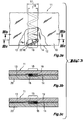
- FIG. 2 (2a and 2b) shows a metal-reinforced layer composite 1 from at least one soft material according to the state the technology, which has a metal insert 2, which in two Layers of a soft material 8 and 9 is embedded.
- This Metal insert 2 as shown in the elevation of Fig. 2a, from two smooth metal foils 3 and 4, which in their Overlap area 5 by a linear weld 6 are welded together.
- the cross section in Fig. 2b along the line IIb-IIb marked in FIG. 2a shows that in this embodiment leakage channels 7 in Longitudinal extent of the overlap area 5 arise due to their poor accessibility not through the Soft layers 8 and 9 are sealed.
- This Leakage channels 7 are for the high leakage rates of Seals responsible, which are composed of such layers 1 can be manufactured as sealing plates.
- Fig. 3 shows an embodiment of a metal reinforced Layer composite 11 of at least one soft material according to of the present invention.
- 3a shows a top view to the metal-reinforced layer composite 11
- metal-reinforced layer composite 11 has a metal insert 12, which are in two layers of a soft material 19 and 20, for example made of expanded graphite.
- the metal insert consists of two metal foils 13 and 14, which by a zigzag-shaped laser beam weld 16 in Overlap area 15 are welded together.
- the Transverse extent 17 of the weld 16 is larger than that maximum width 18 of the overlap area of the two Metal foils 13 and 14.
- the metal-reinforced layer composite 11 is produced according to the invention so that the metal foils welded together in strips, then in plates cut and then with the soft layers 19 and 20 are provided.
- 3b shows a cross section through the metal-reinforced layer composite from FIG. 3a along the line IIIb-IIIb. The cross section shows that the Metal insert 12 between the soft layers 19 and 20 is embedded.
- the metal foils 13, 14 form in this Cross section in the left half of the overlap area no metal foil protrusions, because they are here through the weld 16 are connected. In the right half of the overlap area are not the metal foils 13, 14 interconnected, so that here an open area in the Area of overlap between the metal foils to be connected is present.
- FIG. 3c shows a cross section along the line IIIc-IIIc through the metal-reinforced layer composite from Fig. 3a.
- the line IIIc-IIIc is one half period length of the weld 16 to the line IIIb-IIIb transferred.
- the metal foils 13, 14 in the right half of the overlap area 15 the weld 16 joined together, whereas in the left half of the overlap area unconnected lie on top of each other, so that there is an open area between the metal foils are present in the overlap area.
- the metal-reinforced layer composite therefore has none continuous leakage channels 7 in the longitudinal extension of the Overlap region 15 of the metal foils 13, 14.
- the present embodiment of a metal reinforced Layer composite 11 according to FIG. 3 can be according to the invention can also be modified in such a way that the metal insert 12 is needled after welding to form a tanged sheet obtained, on which the soft fabric lay 19 and 20 be applied.
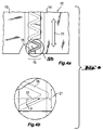
- 4 (4a and 4b) is a possible course weld 16 of the present invention are explained.
- 4a is a metal insert 12 a metal-reinforced layer composite 11 according to the presented present invention.
- the metal insert 12 consists of two overlapping metal foils 13, 14, which by a zigzag weld 16 in Overlap area 15 are welded together.
- the Arrow 21 indicates what is under the longitudinal extension of the Overlap area 15 of the metal foils 13, 14 to understand is.
- Fig. 4b shows a section of the Fig. 4a.
- Fig. 4b are the limits of the overlap area in the form of parallel lines and the weld 16 shown in sections.
- This cutout shows that the weld 16 has a course that a direction component 22 in at least one point P. perpendicular to the longitudinal extent 21 of the overlap area which has metal foils.
- the welding takes place in this Embodiment continuously. This means that the Weld seam in its entire course with the weld line, along which the welding takes
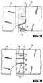
- Fig. 5 shows two metal foils 13, 14 through one Weld seam with sinusoidal weld line in the overlap area 15 according to the present invention are interconnected.
- the welded metal foils 13, 14 form the metal insert 12. This also happened here Welding continuously.
- FIG. 6 shows a metal insert 12 according to the present Invention.
- the metal foils 13, 14 are in the overlap area 15 with a weld 16 with a rung-shaped Welding line (uninterrupted Line guidance) welded.
- the welding was done here discontinuous, especially pulsed.
- the welding is meandering (dashed lines). The offset between the uninterrupted and dashed lines is due to the representation. You actually lie on top of each other.
- Fig. 7 shows a metal-reinforced layer composite 11 at least one soft material with a metal insert 12 contrary to the teaching of the present invention.
- Fig. 7a shows an elevation of the layer composite 11.
- the metal foils 13 and 14 are by a linear weld 16 connected to one another in the overlap region 15.
- the metal insert 12 was needled to weld To create treads.
- the needling was carried out in such a way that no passages 23 in the overlap area 15 of the Metal foils 13 and 14 were created.
- the cut along the Line VIIb-VIIb in Fig. 7b shows that in this layer composite 11 continuous leakage channels 7 in the direction of Longitude of the overlap area 15 of the Metal foils 13, 14 are present, which are right next to the Run weld.
- Fig. 8 shows a metal-reinforced layer composite 11 at least one fabric according to the present Invention.
- Fig. 8a shows an elevation of the sealing plate 11.
- the metal insert 12 consists of two metal foils 13 and 14, which with a linear weld 16 in Overlap region 15 of the metal foils 13, 14 with one another are connected.
- the subsequent needling to create of a skewer was carried out so that in the overlap area 15 passages 23 are present.
- the Passages 23 are greater than or equal to the maximum width 18 of the overlap area 15.
- Applying the soft material layers 19, 20 are the passages 23 filled with soft material. This is shown in Fig. 8b, the one Cross section through the layer composite of FIG. 8a along line VIIIb-VIIIb.
- Fig. 9 shows an annular flat seal 24 according to the Examples and comparative examples of the description of the present invention.
- Such seals are in the Punched out of the sealing plates so that the overlap area 15 of the metal foils e.g. in the illustrated Position.
- D is the width of the seal Seal called. So that such a seal despite the weld seams have no leakage rates that are larger than the leakage rates of seals, which are only one-piece Have metal inserts, is the welding of the Metal foils of the metal insert and / or the attachment of Passages in the overlap area of the metal foils like this list that the extension of possible remaining open areas between the metal foils in the overlap area in the longitudinal direction of the overlap area of the metal foils is smaller than the seal width D.
- Two 50 ⁇ m thick, smooth stainless steel foils (material no. 1.4401) with a width of 540 or 1000 mm were pulled off two braked unwinding units equipped with optical side edge control units.
- the two metal foil webs were continuously guided with an overlap of approx. 1 ⁇ 0.75 mm over a bronze roller. Due to the applied web tension, the two foils were pressed one above the other and sealed in the overlap area at the focal point of an Nd-YAG laser beam (Rofin Sinar, Günding: type RSY 300P1 / CW).
- the laser beam is deflected perpendicular to the overlap area with the help of a pendulum mirror.
- the oscillation amplitude of the laser beam was 1 mm.
- the zero position of the laser beam was identical to the center line of the overlap area.
- the web speed was 0.9 m / min
- the pendulum frequency of the laser beam deflection was 12 Hz
- the welding current was set to 25 A.
- the metal foil web welded in this way was then trimmed to a width of 1500 mm and wound up with a torque-controlled winding device.
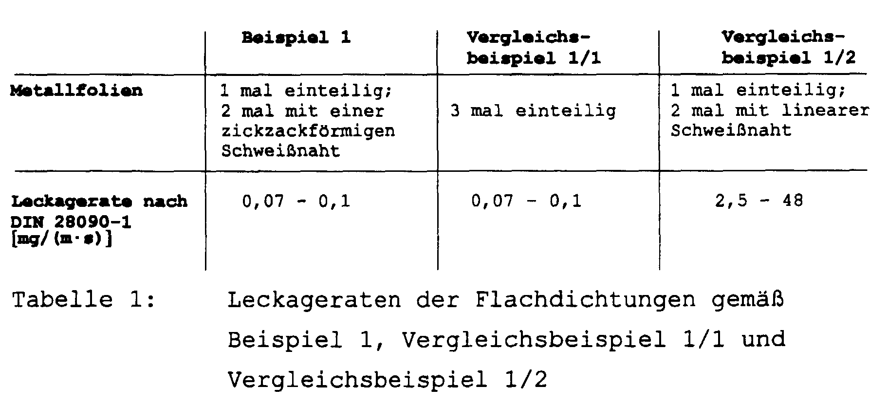
- a metal foil-reinforced layer composite was produced on the basis of graphite foil as a sealing plate using the method described in EP 0 616 884 B1.
- This metal-reinforced sealing plate consisted of 4 layers of 0.5 mm thick graphite foil with a density of 1.1 g / cm 3 and three layers of metal foil. The sequence of the layers was graphite foil / welded metal foil / graphite foil / one-piece metal foil / graphite foil / welded metal foil / graphite foil.
- This sealing plate was used as in Example 1 Flat seals punched out and their leakage rates after DIN 28090-1 determines (see Table 1).
- Metal foils 0.1 mm thick were used in this example.
- the welding parameters of the zigzag-shaped weld seam were: vibration frequency 12 Hz, lamp current 31 A, pendulum swing width approx. 1.3 mm.
- the web speed was 1.8 m / min, the width of the overlap area of the films fluctuated between approximately 0.4 and 1.5 mm.
- the welded metal foils were then needled so that a skewer was available.
- a layer composite was mechanically connected with the layer sequence of graphite foil (thickness 1 mm, density 1.0 g / cm 3 ) / welded tipped sheet / graphite foil (thickness 1 mm, density 1.0 g / cm 3 ) as a sealing plate.
- graphite foil thickness 1 mm, density 1.0 g / cm 3
- This sealing plate was used as in Example 1 Flat seals punched out and the leakage rates according to DIN 28090-1 determined (see Table 2).
- a sealing plate as described in Example 2 was used made, however, the tread insert in one piece was. Again flat gaskets were punched out and Leakage rates measured (see Table 2).
- a sealing plate as described in Example 2 was used made, however, the tanged insert had linear weld, as shown in Fig. 7.
- the The tanged sheet therefore had no passages in the overlap area of the metal foils.
- the leakage rates of the flat seals, which are punched out of this sealing plate were also shown in Table 2.
- a gasket sheet was made as described in Example 2, but the tipped sheet insert had a linear weld, as shown in FIG. 8.
- the tanged sheet thus had passages in the overlap area of the metal foils, which covered the entire overlap area.
- the leakage rates of the flat seals that were punched out of this sealing plate are also shown in Table 2.
- Table 2 shows that the determined leakage rates of Flat seals with the zigzag weld or the linear weld with passages in the overlap area the metal foils are essentially identical to the Leakage rates of the one-piece tinned flat gaskets were.
- the leakage rates were measured in all the above examples according to DIN 28090-1 in accordance with the test regulations for the preliminary test in accordance with Chapter 7.3.3.
- the leakage rates of the sealing plates were carried out with a sealing surface pressure after internal pressure relief of 30 N / mm 2 and a test pressure of 40 bar of nitrogen gas. Sampling, sample dimensions and sample pre-conditioning as well as the test device corresponded to the DIN standard 28090-1. Five samples were tested for each of the preceding examples.
Landscapes
- Engineering & Computer Science (AREA)
- Mechanical Engineering (AREA)
- General Engineering & Computer Science (AREA)
- Laminated Bodies (AREA)
- Gasket Seals (AREA)
- Arc Welding In General (AREA)
Abstract
Description
Zum einen erfolgt die Verbindung dadurch, daß zwischen den sich überlappenden Folienenden ein Kleber wie z.B. Epoxidharz eingebracht wird, der aushärtet. Zumeist wird hierbei der Kleber über den gesamten Überlappungsbereich auf mindestens einer der zu verbindenden Metallfolien aufgebracht. Das Verkleben der Metallfolien hat den Nachteil, daß Dichtungen, die aus Schichtverbunden hergestellt wurden, die derartig verbundene Metalleinlagen aufweisen, nur in einem eng begrenzten Temperaturbereich eingesetzt werden können. Dies ist dadurch bedingt, daß bei höheren Temperaturen der Klebstoff erweicht und/oder teilweise thermisch abgebaut wird. Hierdurch können zum einen in den Dichtungen die Metallfolien an ihren verklebten Verbindungsstellen unter mechanischer Beanspruchung wie Zugkräften in Richtung der Metallfolien und Druckkräften senkrecht zu den Metalleinlagen leichter gegeneinander abscheren, wodurch die mechanische Stabilität der Dichtungen verringert wird. Durch einen thermischen Abbau des Klebers bleiben im Überlappungsbereich zwischen den verklebten Metallfolienenden nur poröse, undichte pyrolysierte Rückstände des Klebers bestehen. Wenn die hierdurch im Kleber entstandenen Poren ineinander übergehen, können über größere Längen durchgehende Kanäle im Kleberrückstand entstehen, die bei einer Dichtung sich auch vom einen bis zum anderen Dichtungsrand erstrecken können, was dann zu einer wesentlichen Erhöhung der Leckagerate der Dichtung führt, da durch diese Kanäle ein abzudichtendes Medium aus der Dichtung austreten kann. Im weiteren werden derartige Kanäle, die sich von einem Dichtungsrand zum anderen in einer Dichtung erstrecken, als Leckagekanäle der Dichtung bezeichnet. Dichtungen mit Metalleinlagen, die aus miteinander verklebten Metallfolien bestehen, neigen also dazu, bei erhöhten Temperaturen höhere Leckageraten aufzuweisen. Zusätzlich ist die Einsatzmöglichkeit von Dichtungen, die Metalleinlagen mit miteinander verklebten Metallfolien aufweisen auf Medien beschränkt, die den Klebstoff nicht angreifen, da andernfalls durch den Angriff des Mediums am Kleber zum einen wiederum ein Abscheren der Metallfolien durch mechanische Beanspruchungen möglich ist und somit die mechanische Stabilität der Dichtungen verringert wird und zum anderen auch durch den Abbau des Klebstoffs durch das abzudichtende aggressive Medium sich im Klebstoff ähnlich wie bei hohen Temperaturen Leckagekanäle ausbilden können, so daß die Dichtwirkung der Dichtung nicht mehr garantiert ist. Daher ist für die universelle Verwendung von Dichtungen, die aus Schichtverbunden hergestellt werden, die aus mindestens zwei Metallfolien verbundene Metalleinlagen aufweisen, notwendig, daß die Verbindung der Metallfolien dieser Metalleinlagen ohne das Einbringen weiterer Medien wie z.B. Klebstoffe in die Dichtungen erfolgt.
Als Schweißverfahren können prinzipiell alle bekannten Schweißverfahren wie Preßschweißen, Schmelzschweißen, Widerstandsschweißen und Strahlschweißen angewendet werden. Hierbei werden kontinuierliche und diskontinuierliche Verfahren angewandt. Bei überlappt angeordneten Blechen wird vor allem Widerstandsschweißen in Form von Punktschweißen (diskontinuierliches Schweißen) und Rollnahtschweißen (kontinuierliches Schweißen) angewendet. Beim Punktschweißen werden die Schweißelektroden in der Mitte des Überlappungsbereichs auf die beiden zu verschweißenden Metallfolien aufgesetzt und dann die Folien durch ein Stromimpuls aufgeschmolzen und verbunden. Beim Rollnahtschweißen werden scheibenförmige Elektrodenrollen angewendet, durch die die sich überlappenden Enden der Folienbahnen gezogen werden. Hierdurch wird eine lineare Schweißnaht erzeugt, die in der Mitte des Überlappungsbereichs verläuft. Die Lage von Schweißpunkten bzw. Schweißnaht wird mittig gewählt, um zu garantieren, daß die Schweißelektroden bzw. Schweißelektrodenrollen beim Schweißen in ihrer ganzen Breite die beiden Metallfolien kontaktieren, da andernfalls ein zu hoher Flächenstrom zu einem Wegbrennen der Metallfolien an der Schweißstelle führen kann. Weiterhin kann auch Laserstrahlschweißen zum Verbinden der Metallfolien in ihrem Überlappungsbereich eingesetzt werden. Hierbei wird die Energie des Laserstrahls von den Metallfolien in Form von Wärme absorbiert, wodurch die Metallfolien verschmelzen. Um ein sicheres und einfaches Verschweißen der Metallfolien zu garantieren, sollte der Laserstrahl in der Mitte des Überlappungsbereichs positioniert und die beiden sich überlappenden Metallfolienbahnen relativ zum feststehenden Laser bewegt werden. Es kann somit eine lineare stoffschlüssige Schweißnaht im Überlappungsbereich der Folien erzeugt werden.
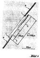
- Fig. 1
- zeigt ein Schliffbild von glatten 50 µm dicken Metallfolien, die gemäß des Standes der Technik überlappt und mit einer linearen Schweißnaht verbunden wurden. Hiermit werden die auftretenden Leckagekanäle dargestellt.
- Fig. 2
- zeigt einen Aufriß eines metallverstärkten
Schichtverbunds 1 gemäß des Standes der Technik.
- Fig. 2a stellt einen Aufriß dar.
- Fig. 2b zeigt einen Schnitt entlang der Linie IIb-IIb durch die Dichtungsplatte 1 gemäß Fig. 2a.
- Fig. 3
- zeigt eine Ausführungsform einer metallverstärkten
Dichtungsplatte 11 gemäß der
vorliegenden Erfindung.
- Fig. 3a stellt einen Aufriß dar.
- Fig. 3b zeigt einen Schnitt durch die Dichtungsplatte 11 gemäß Fig. 3a entlang der Linie IIIb-IIIb.
- Fig. 3c zeigt einen Schnitt durch die Dichtungsplatte 11 gemäß Fig. 3a entlang der Linie IIIc-IIIc, die um eine halbe Periodenlänge der Schweißnaht 16 zur Linie IIIb-IIIb versetzt liegt.
- Fig. 4
- zeigt eine Metalleinlage 12 mit einer möglichen
Schweißlinie gemäß der vorliegenden Erfindung.
- Fig. 4a zeigt eine Draufsicht.
- Fig. 4b stellt einen Ausschnitt aus dem in Fig. 4a dargestellten Schweißnaht verlauf dar.
- Fig. 5 u.6
- zeigen weitere Draufsichten auf Metalleinlagen 12 mit möglichen Schweißlinienverläufen gemäß der vorliegenden Erfindung.
- Fig. 7
- zeigt eine Ausführungsform einer metallverstärkten
Dichtungsplatte 11 entgegen der
Lehre der vorliegenden Erfindung
- Fig. 7a stellt eine Draufsicht dar.
- Fig. 7b ist ein Querschnitt durch die metallverstärkte Dichtungsplatte gemäß Fig. 7a entlang der Linie VIIb-VIIb.
- Fig. 8
- zeigt eine Ausführungsform einer metallverstärkten
Dichtungsplatte 11 gemäß der vorliegenden
Erfindung.
- Fig. 8a stellt eine Draufsicht dar.
- Fig. 8b ist ein Querschnitt durch die metallverstärkte Dichtungsplatte der Fig. 8a entlang der Linie VIIIb-VIIIb.
- Fig. 9
- zeigt Flachdichtungen 24 gemäß der Beispiele und Vergleichsbeispiele der Beschreibung der vorliegenden Erfindung.


- 1
- metallverstärkter Schichtverbund (Dichtungsplatte)
- 2
- Metalleinlage
- 3
- Metallfolie
- 4
- Metallfolie
- 5
- Überlappungsbereich der Metallfolien 3 und 4
- 6
- lineare Schweißnaht
- 7
- Leckagekanal
- 8
- Weichstofflage
- 9
- Weichstofflage
- 11
- metallverstärkter Schichtverbund (Dichtungsplatte)
- 12
- Metalleinlage
- 13
- Metallfolie
- 14
- Metallfolie
- 15
- Überlappungsbereich der Metallfolien 13 und 14
- 16
- Schweißnaht
- 17
- Quererstreckung der Schweißnaht 16
- 18
- maximale Breite des Überlappungsbereiches 15
- 19
- Weichstofflage
- 20
- Weichstofflage
- 21
- Längserstreckung des Überlappungsbereiches 15
- 22
- Richtungskomponente der Schweißnaht 16 senkrecht zur Längserstreckung 21
- 23
- Durchgang
- 24
- Flachdichtung
- D
- Dichtungsbreite
- L
- Leckagekanal
- M
- Metallfolie
- P
- Punkt
- Q
- Breite des Überlappungsbereiches
- R
- Metallfolienüberstand
Claims (70)
- Metallverstärkter Schichtverbund (11) aus einem oder mehreren Weichstoffen aufweisend mindestens eine Metalleinlage (12), wobei mindestens eine dieser Metalleinlagen (12) aus mindestens zwei sich mindestens partiell überlappender Metallfolien (13, 14) besteht, die durch mindestens eine Schweißnaht (16) und/oder Verklammern in dem Überlappungsbereich (15) miteinander verbunden sind,
dadurch gekennzeichnet, daß
an jeder im Schichtverbund (11) vorhandenen Schweißnaht (16), durch die zwei Metallfolien (13, 14) verbunden werden und in jedem Überlappungsbereich, wo zwei Metallfolien durch Verklammern verbunden sind, keine und/oder keine durchgehenden Leckagekanäle (7) in Längserstreckung (21) des Überlappungsbereiches (15) vorhanden sind. - Metallverstärkter Schichtverbund (11) nach Patentanspruch 1, wobei der Schichtverbund zusätzlich auf seinen nach außen weisenden Flachseiten vollständig mit einer gasdichten Folie aus einem organischen Polymer bedeckt und verbunden ist.
- Metallverstärkter Schichtverbund (11) nach Patentanspruch 1 oder 2, wobei die maximale Länge eines nicht durchgehenden Leckagekanals in Längserstreckung (21) des Überlappungsbereiches (15) kleiner als 25 mm ist.
- Metallverstärkter Schichtverbund (11) nach Patentanspruch 1 oder 2, wobei die maximale Länge eines nicht durchgehenden Leckagekanals in Längserstreckung (21) des Überlappungsbereiches (15) zwischen 0,5 und 5 mm liegt.
- Metallverstärkter Schichtverbund (11) nach Patentanspruch 1 oder 2, wobei die maximale Länge eines nicht durchgehenden Leckagekanals in Längserstreckung (21) des Überlappungsbereiches (15) zwischen 1 und 2 mm liegt.
- Metallverstärkter Schichtverbund (11) nach einem der Patentansprüche 1 bis 5, wobei die maximale Breite (18) des Überlappungsbereichs (15) der Metallfolien (13, 14) kleiner als 10 mm ist.
- Metallverstärkter Schichtverbund (11) nach einem der Patentansprüche 1 bis 5, wobei die maximale Breite (18) des Überlappungsbereichs (15) der Metallfolien (13, 14) zwischen 0,2 mm und 2 mm beträgt.
- Metallverstärkter Schichtverbund (11) nach einem der Patentansprüche 1 bis 5, wobei die maximale Breite (18) des Überlappungsbereichs (15) der Metallfolien (13, 14) zwischen 0,5 mm und 1 mm beträgt.
- Metallverstärkter Schichtverbund (11) nach einem der Patentansprüche 1 bis 8, wobei eine Überlappung der Metallfolien (13, 14) in deren voller Länge vorliegt.
- Metallverstärkter Schichtverbund (11) nach einem der Patentansprüche 1 bis 9, wobei mindestens eine der Schweißnähte (16) einen Verlauf aufweist, der in mindestens einem Punkt (P) eine Richtungskomponente (22) senkrecht zur Längserstreckung (21) des Überlappungsbereiches (15) der Metallfolien (13, 14) aufweist.
- Metallverstärkter Schichtverbund (11) nach einem der Patentansprüche 1 bis 10, wobei mindestens eine der Schweißnähte (16) ohne Unterbrechung entlang des Überlappungsbereichs (15) verläuft.
- Metallverstärkter Schichtverbund (11) nach einem der Patentansprüche 1 bis 11, wobei der Verlauf der Schweißnaht (16) entlang des Überlappungsbereichs (15) periodisch ist.
- Metallverstärkter Schichtverbund (11) nach einem der Patentansprüche 1 bis 12, wobei mindestens eine der Schweißnähte (16) einen sinusförmigen, mäanderförmigen, zickzackförmigen oder leitersprossenförmigen Verlauf aufweist.
- Metallverstärkter Schichtverbund (11) nach einem der Patentansprüche 12 und 13, wobei die Periodenlänge des periodischen Verlaufs der Schweißnaht (16) kleiner als 25 mm ist.
- Metallverstärkter Schichtverbund (11) nach einem der Patentansprüche 12 und 13, wobei die Periodenlänge des periodischen Verlaufs der Schweißnaht (16) zwischen 0,5 mm und 5 mm beträgt.
- Metallverstärkter Schichtverbund (11) nach einem der Patentansprüche 12 und 13, wobei die Periodenlänge des periodischen Verlaufs der Schweißnaht (16) zwischen 1 mm und 2 mm beträgt.
- Metallverstärkter Schichtverbund (11) nach einem der Patentansprüche 12 bis 16, wobei die Periodenlänge des periodischen Verlaufs der Schweißnaht (16) entlang des Überlappungsbereichs (15) variiert.
- Metallverstärkter Schichtverbund (11) nach einem der voranstehenden Patentansprüche, wobei die Quererstreckung (17) der Schweißnaht (16) größer oder gleich der maximalen Breite (18) des Überlappungsbereiches (15) der Metallfolien (13, 14) ist.
- Metallverstärkter Schichtverbund (11) nach einem der voranstehenden Patentansprüche, wobei die Quererstreckung (17) der Schweißnaht (16) etwa 1 bis etwa 2 mal die maximale Breite (18) des Überlappungsbereiches (15) der Metallfolien (13, 14) ist.
- Metallverstärkter Schichtverbund (11) nach einem der Patentansprüche 1 bis 19, wobei mindestens eine der Schweißnähte (16) des Schichtverbundes (11) mindestens eine Unterbrechung entlang der Längserstreckung (21) des Überlappungsbereiches (15) aufweist.
- Metallverstärkter Schichtverbund (11) nach einem der Patentansprüche 1 bis 20, wobei das Verschweißen der Metallfolien (13, 14) ganz oder teilweise im Pulsbetrieb ausgeführt ist, wobei die Breite der Schweißpunkte größer oder gleich als die maximale Breite (18) des Überlappungsbereichs (15) der Metallfolien (13, 14) ist.
- Metallverstärkter Schichtverbund (11) nach einem der Patentansprüche 1 bis 20, wobei das Verschweißen der Metallfolien (13, 14) ganz oder teilweise im Pulsbetrieb ausgeführt ist, wobei sich mindestens zum Teil die Schweißpunkte in ihrer Erstreckung überlappen.
- Metallverstärkter Schichtverbund (11) nach einem der Patentansprüche 21 oder 22, wobei sich mindestens zum Teil die Schweißpunkte in konstanten Abständen entlang der Längserstreckung (21) des Überlappungsbereichs (15) befinden.
- Metallverstärkter Schichtverbund (11) nach einem der Patentansprüche 21 bis 23, wobei mindestens zum Teil in Längsrichtung des Überlappungsbereichs (15) aufeinander folgende Schweißpunkte in Richtung der Breite des Überlappungsbereichs (15) gegeneinander versetzt sind.
- Metallverstärkter Schichtverbund (11) nach einem der Patentansprüche 21 bis 24, wobei mindestens zum Teil in Längsrichtung des Überlappungsbereichs (15) aufeinander folgende Schweißpunkte im Wechsel in Richtung der Breite des Überlappungsbereichs (15) auf der einen bzw. anderen Seite des Überlappungsbereichs (15) positioniert sind.
- Metallverstärkter Schichtverbund (11) nach einem der Patentansprüche 1 bis 9, wobei mindestens eine aus mindestens zwei Metallfolien (13, 14) bestehende Metalleinlage (12) mindestens einen Durchgang (23) im Überlappungsbereich (15) der Metallfolien (13, 14) aufweist.
- Metallverstärkter Schichtverbund (11) nach einem der Patentansprüche 10 bis 25, wobei mindestens eine der aus mindestens zwei Metallfolien (13, 14) bestehende Metalleinlage (12) zusätzlich mindestens einen Durchgang (23) im Überlappungsbereich (15) der Metallfolien (13, 14) aufweist.
- Metallverstärkter Schichtverbund (11) nach einem der Patentansprüche 26 und 27, wobei der mindestens eine Durchgang (23) größer oder gleich der maximalen Breite (18) des Überlappungsbereiches (15) der Metallfolien (13, 14) ist.
- Metallverstärkter Schichtverbund (11) nach einem der Patentansprüche 26 bis 28, wobei der Überlappungsbereich (15) in Abständen entlang des Überlappungsbereichs (15) Durchgänge (23) aufweist.
- Metallverstärkter Schichtverbund (11) nach einem der Patentansprüche 26 bis 29, wobei der Überlappungsbereich (15) in konstanten Abständen entlang des Überlappungsbereichs (15) Durchgänge (23) aufweist.
- Metallverstärkter Schichtverbund (11) nach einem der Patentansprüche 29 oder 30, wobei der Abstand der Durchgänge (23) entlang des Überlappungsbereichs (15) maximal 25 mm beträgt.
- Metallverstärkter Schichtverbund (11) nach einem der Patentansprüche 29 oder 30, wobei der maximale Abstand der Durchgänge (23) entlang des Überlappungsbereichs (15) zwischen 1 mm und 10 mm liegt.
- Metallverstärkter Schichtverbund (11) nach einem der Patentansprüche 29 oder 30, wobei der maximale Abstand der Durchgänge (23) entlang des Überlappungsbereichs (15) zwischen 3 und 5 mm liegt.
- Metallverstärkter Schichtverbund (11) nach einem der Patentansprüche 1 bis 11, wobei mindestens eine der Schweißnähte (16) mindestens teilweise einen linearen, zur Längserstreckung (21) des Überlappungsbereiches (15) der Metallfolien (13, 14) parallelen Verlauf aufweist.
- Metallverstärkter Schichtverbund (11) nach Patentanspruch 34, wobei die Breite mindestens einer der Schweißnähte (16), die einen linearen, zur Längserstreckung (21) des Überlappungsbereiches (15) der Metallfolien (13, 14) parallelen Verlauf aufweisen, mindestens teilweise größer oder gleich als die maximale Breite (18) des Überlappungsbereichs (15) ist.
- Metallverstärkter Schichtverbund (11) nach Patentanspruch 34, wobei mindestens eine der Schweißnähte (16), die einen linearen, zur Längserstreckung (21) des Überlappungsbereiches (15) der Metallfolien (13, 14) parallelen Verlauf aufweisen, mindestens teilweise dadurch ausgeführt ist, daß mehrere Schweißnähte mit einen linearen, zur Längserstreckung (21) des Überlappungsbereiches (15) der Metallfolien (13, 14) parallelen Verlauf nebeneinander gelegt sind, wobei sie sich überlappen und die Gesamtbreite der hierdurch resultierenden Gesamtschweißnaht größer oder gleich als die maximale Breite (18) des Überlappungsbereiches (15) der Metallfolien (13, 14) ist.
- Metallverstärkter Schichtverbund (11) gemäß Patentanspruch 34, wobei zusätzlich mindestens eine der Schweißnähte (16), die einen linearen, zur Längserstreckung (21) des Überlappungsbereiches (15) der Metallfolien (13, 14) parallelen Verlauf aufweisen, mindestens teilweise kombiniert wird mit mindestens einer Schweißnaht (16), die einen Verlauf aufweist, der mindestens in einem Punkt P eine Richtungskomponente (22) senkrecht zur Längserstreckung (21) des Überlappungsbereichs (15) aufweist.
- Metallverstärkter Schichtverbund (11) nach einem der voranstehenden Patentansprüche aufweisend mindestens eine Lage (19) mindestens eines Weichstoffes und mindestens eine Metalleinlage (12).
- Metallverstärkter Schichtverbund (11) nach einem der voranstehenden Patentansprüche, wobei die Metallfolien (13, 14) eine Dicke bis zu etwa 250 µm aufweisen.
- Metallverstärkter Schichtverbund (11) nach einem der voranstehenden Patentansprüche, wobei die Metallfolien (13, 14) eine Dicke im Bereich von etwa 25 µm bis etwa 125 µm aufweisen.
- Metallverstärkter Schichtverbund (11) nach einem der voranstehenden Patentansprüche, wobei die Metallfolien (13, 14) eine Dicke im Bereich von etwa 50 bis etwa 100 µm aufweisen.
- Metallverstärkter Schichtverbund (11) nach einem der voranstehenden Patentansprüche, wobei die Metallfolien (13, 14) aus Stahl, Nickel oder Chrom-Nickel-Stahl bestehen.
- Metallverstärkter Schichtverbund (11) nach einem der Patentansprüche 1 bis 42, der mindestens zwei Lagen (19, 20) aus mindestens einem Weichstoff und darin eingebettet mindestens eine Metalleinlage (12) aufweist.
- Metallverstärkter Schichtverbund (11) nach einem der Patentansprüche 1 bis 43, der nur einen Weichstoff aufweist.
- Metallverstärkter Schichtverbund (11) nach einem der Patentansprüche 1 bis 44, wobei einer der im Schichtverbund (11) enthaltenen Weichstoffe ein Weichstoff aus der Gruppe expandierter Graphit, PTFE oder Glimmer ist.
- Metallverstärkter Schichtverbund (11] nach einem der Patentansprüche 1 bis 44, wobei jeder der im Schichtverbund (11) enthaltenen Weichstoffe ein Weichstoff aus der Gruppe expandierter Graphit, PTFE oder Glimmer ist.
- Metallverstärkter Schichtverbund (11) nach einem der Patentansprüche 1 bis 44, wobei der Schichtverbund (11) nur einen Weichstoff aus der Gruppe expandierter Graphit, PTFE oder Glimmer beinhaltet.
- Metallverstärkter Schichtverbund (11) nach einem der voranstehenden Patentansprüche, wobei mindestens eine Metalleinlage (12) aus Spießblech besteht.
- Metallverstärkter Schichtverbund (11) nach einem der voranstehenden Patentansprüche, wobei alle Schweißnähte (16) im Schichtverbund (11), die Metallfolien (13, 14) verbinden, Widerstands- und/oder Laserstrahlschweißnähte sind.
- Verwendung eines metallverstärkten Schichtverbundes (11) nach einem der voranstehenden Patentansprüche als Dichtungsplatte.
- Verwendung eines metallverstärkten Schichtverbundes (11) nach einem der voranstehenden Patentansprüche zur Herstellung von Flachdichtungen (24) oder Stopfbuchspackungen.
- Verfahren zur Herstellung eines metallverstärkten Schichtverbundes (11) aus mindestens einem Weichstoff aufweisend:
mindestens einmal erfolgendes Verschweißen von mindestens zwei sich mindestens partiell überlappenden Metallfolien (13, 14) im Überlappungsbereich (15) zur Schaffung einer Metalleinlage (12),
dadurch gekennzeichnet, daß
die Verschweißung der Metallfolien (13, 14) so ausgeführt wird, daß es im Überlappungsbereich (15) zwischen den Metallfolien (13, 14) keine und/oder keine in Längserstreckung (21) des Überlappungsbereiches (15) durchgehenden offenen Bereiche (7) gibt. - Verfahren zur Herstellung eines metallverstärkten Schichtverbundes (11) aus mindestens einem Weichstoff nach Patentanspruch 52
dadurch gekennzeichnet, daß
die Verschweißung der Metallfolien (13, 14) so ausgeführt wird, daß die offenen Bereiche im Überlappungsbereich (15) zwischen den Metallfolien (13, 14) in Längserstreckung (21) des Überlappungsbereiches (15) eine begrenzte Ausdehnung aufweisen. - Verfahren zur Herstellung eines metallverstärkten Schichtverbundes (11) aus mindestens einem Weichstoff nach Patentanspruch 53
dadurch gekennzeichnet, daß
die Verschweißung der Metallfolien (13, 14) so ausgeführt wird, daß die offenen Bereiche im Überlappungsbereich (15) zwischen den Metallfolien (13, 14) in Längserstreckung (21) des Überlappungsbreiches (15) eine maximale Ausdehnung aufweisen, die kleiner als 25 mm ist. - Verfahren nach einem der Patentansprüche 52 bis 54, wobei das Schweißen der sich überlappenden Metallfolien (13, 14) im Überlappungsbereich (15) mindestens teilweise dadurch erfolgt, daß das Schweißen entlang einer Linie durchgeführt wird, die mindestens in einem Punkt (P) eine Richtungskomponente (22) senkrecht zur Längserstreckung (21) des Überlappungsbereichs (15) der Metallfolien (13, 14) aufweist.
- Verfahren nach einem der Patentansprüche 52 bis 55, bei dem das Schweißen mindestens teilweise derart erfolgt, daß mindestens ein Schweißvorgang entlang einer linearen, zur Längserstreckung (21) des Überlappungsbereiches (15) der Metallfolien (13, 14) parallelen Linie durchgeführt wird.
- Verfahren nach einem der Patentansprüche 52 bis 55, bei dem das Schweißen mindestens teilweise derart erfolgt, daß es entlang der Längsrichtung (21) des Überlappungsbereichs (15) in einer sinusförmigen, mäanderförmigen, zickzackförmigen oder treppenförmigen Linie durchgeführt wird.
- Verfahren nach einem der Patentansprüche 52 bis 57, wobei das Schweißen pulsierend und/oder kontinuierlich erfolgt.
- Verfahren nach einem der Patentansprüche 52 bis 58, bei dem die Quererstreckung (17) beim Schweißen mindestens teilweise größer oder gleich der maximalen Breite (18) des Überlappungsbereiches (15) der Metallfolien (13, 14) ist.
- Verfahren nach einem der Patentansprüche 52 bis 59, bei dem die Quererstreckung (17) beim Schweißen mindestens teilweise etwa 1 bis etwa 2 mal der Quererstreckung (18) des Überlappungsbereichs (15) der Metallfolien (13, 14) ist.
- Verfahren nach einem der Patentansprüche 52 bis 60, bei dem das Schweißen durch Widerstands- und/oder Laserstrahlschweißen erfolgt.
- Verfahren zur Herstellung eines metallverstärkten Schichtverbundes (11) aus mindestens einem Weichstoff aufweisend:
mindestens einmal erfolgendes Verschweißen von mindestens zwei sich mindestens partiell überlappenden Metallfolien (13, 14) im Überlappungsbereich (15) zur Schaffung einer Metalleinlage (12),
dadurch gekennzeichnet, daß
die Metalleinlage (12) mit mindestens einem Durchgang (23) im Überlappungsbereich (15) der Metallfolien (13, 14) versehen wird. - Verfahren nach Patentanspruch 62, wobei die Metalleinlage (12) mit zahlreichen Durchgängen (23) im Überlappungsbereich (15) und außerhalb des Überlappungsbereiches (15) versehen wird, um ein Spießblech zu schaffen.
- Verfahren nach einem der Patentansprüche 52 bis 63, wobei die mindestens eine Metalleinlage (12) mit mindestens einer weiteren Lage (19, 20) aus mindestens einem Weichstoff verbunden wird.
- Verwendung eines metallverstärkten Schichtverbundes (11), hergestellt nach dem in den Patentansprüchen 52 bis 64 beschriebenen Verfahren zur Herstellung von Flachdichtungen (24) oder Stopfbuchspackungen.
- Dichtung, die aus einem in den Patentansprüchen 1 bis 49 beschriebenen metallverstärkten Schichtverbund (11) hergestellt ist.
- Dichtung nach Patentanspruch 66, wobei die Schweißnaht (16) eine Periodenlänge aufweist, die geringer ist als die Dichtungsbreite (D) der Dichtung.
- Verwendung von Metallfolien (12), die aus mindestens zwei sich mindestens
partiell überlappenden Metallfolien (13, 14) bestehen, die durch mindestens eine Schweißnaht (16) und/oder Verklammern in dem Überlappungsbereich (15) miteinander verbunden sind,
dadurch gekennzeichnet, daß
es an jeder der zwei Metallfolien (13, 14) verbindenden Schweißnähte (16) im Überlappungsbereich (15) zwischen den Metallfolien (13, 14) und in jedem Überlappungsbereich (15), wo zwei Metallfolien (13, 14) durch Verklammern verbunden sind, keine und/oder keine in Längserstreckung (21) des Überlappungsbereichs (15) durchgehenden offenen Bereiche vorhanden sind, zur Herstellung von metallverstärkten Schichtverbunden (11) aus mindestens einem Weichstoff. - Verwendung von Metallfolien (12), die aus mindestens zwei sich mindestens
partiell überlappenden Metallfolien (13, 14) bestehen, die durch mindestens eine Schweißnaht (16) und/oder Verklammern in dem Überlappungsbereich (15) miteinander verbunden sind,
dadurch gekennzeichnet, daß
es an jeder der zwei Metallfolien (13, 14) verbindenden Schweißnähte (16) im Überlappungsbereich (15) zwischen den Metall folien (13, 14) und in jedem Überlappungsbereich (15), wo zwei Metallfolien (13, 14) durch Verklammern verbunden sind, keine und/oder keine in Längserstreckung (21) des Überlappungsbereichs (15) durchgehenden offenen Bereiche vorhanden sind, zur Herstellung von metallverstärkten Dichtungsplatten aus mindestens einem Weichstoff. - Verwendung von Metallfolien (12), die aus mindestens zwei sich mindestens
partiell überlappenden Metallfolien (13, 14) bestehen, die durch mindestens eine Schweißnaht (16) und /oder Verklammern in dem Überlappungsbereich (15) miteinander verbunden sind,
dadurch gekennzeichnet, daß
es an jeder der zwei Metallfolien (13, 14) verbindenden Schweißnähte (16) im Überlappungsbereich (15) zwischen den Metallfolien (13, 14) und in jedem Überlappungsbereich (15), wo zwei Metallfolien (13, 14) durch Verklammern verbunden snd, keine und/oder keine in Längs erstreckung (21) des Überlappungsbereichs (15) durchgehenden offenen Bereiche vorhanden sind, zur Herstellung von metallverstärkten Dichtungen, insbesondere Flachdichtungen (24) aus mindestens einem Weichstoff.
Applications Claiming Priority (2)
| Application Number | Priority Date | Filing Date | Title |
|---|---|---|---|
| DE19930931 | 1999-07-06 | ||
| DE19930931A DE19930931A1 (de) | 1999-07-06 | 1999-07-06 | Schichtverbund mit geschweißter Metalleinlage |
Publications (3)
| Publication Number | Publication Date |
|---|---|
| EP1066956A2 true EP1066956A2 (de) | 2001-01-10 |
| EP1066956A3 EP1066956A3 (de) | 2001-11-28 |
| EP1066956B1 EP1066956B1 (de) | 2004-10-13 |
Family
ID=7913684
Family Applications (1)
| Application Number | Title | Priority Date | Filing Date |
|---|---|---|---|
| EP00113982A Expired - Lifetime EP1066956B1 (de) | 1999-07-06 | 2000-07-01 | Schichtverbund mit geschweisster Metalleinlage |
Country Status (8)
| Country | Link |
|---|---|
| US (1) | US6579626B1 (de) |
| EP (1) | EP1066956B1 (de) |
| JP (1) | JP4833395B2 (de) |
| AT (1) | ATE279318T1 (de) |
| CA (1) | CA2313597C (de) |
| CZ (1) | CZ300759B6 (de) |
| DE (2) | DE19930931A1 (de) |
| PL (1) | PL200241B1 (de) |
Cited By (1)
| Publication number | Priority date | Publication date | Assignee | Title |
|---|---|---|---|---|
| EP1840363A1 (de) * | 2006-03-29 | 2007-10-03 | ElringKlinger AG | Flachdichtung, insbesondere Zylinderkopfdichtung |
Families Citing this family (15)
| Publication number | Priority date | Publication date | Assignee | Title |
|---|---|---|---|---|
| DE19959090A1 (de) * | 1999-12-08 | 2001-06-13 | Prym William Gmbh & Co Kg | Verbindung zwischen zwei- oder mehrflächig aufeinanderliegenden dünnen bahnförmigen Lagen, insbesondere zwischen zwei eine kontinuierliche Behandlung erfahrenden Bänder |
| US7994449B2 (en) * | 2000-02-16 | 2011-08-09 | Advanced Cardiovascular Systems, Inc. | Square-wave laser bonding |
| JP4413491B2 (ja) * | 2002-12-11 | 2010-02-10 | 矢崎総業株式会社 | 電線と接続端子との接続方法 |
| AU2007223485B2 (en) * | 2006-03-07 | 2010-12-16 | Daikin Industries, Ltd. | Method for producing compressor, and compressor |
| DE102006040650A1 (de) * | 2006-08-30 | 2008-03-13 | Robert Bosch Gmbh | Verfahren zum Fügen von Bauteilen mit geschlossenem Hohlquerschnitt |
| ES2375880T3 (es) * | 2008-07-30 | 2012-03-07 | Ipg Photonics Corporation | Útil de soldadura por l�?ser con un l�?ser de fibra. |
| KR101055462B1 (ko) * | 2010-01-07 | 2011-08-08 | 삼성전기주식회사 | 인쇄회로기판 제조용 캐리어와 그 제조방법 및 이를 이용한 인쇄회로기판의 제조방법 |
| CA2789437A1 (en) | 2010-02-17 | 2011-08-25 | Sanofi-Aventis Deutschland Gmbh | Injection device |
| JP5875077B2 (ja) * | 2012-11-13 | 2016-03-02 | キャタピラー エス エー アール エル | 溶接構造および作業機械 |
| US20150115548A1 (en) * | 2013-10-29 | 2015-04-30 | Virginia Sealing Products, Inc. | Composite gasket |
| JP6819479B2 (ja) * | 2017-06-21 | 2021-01-27 | トヨタ自動車株式会社 | 金属部材及びその製造方法 |
| JP7027122B2 (ja) * | 2017-10-27 | 2022-03-01 | シロキ工業株式会社 | 車両用ドアサッシュのシーム溶接方法 |
| JP7112647B2 (ja) * | 2018-08-28 | 2022-08-04 | 日本ガスケット株式会社 | ガスケット |
| FR3092024B1 (fr) * | 2019-01-29 | 2021-09-17 | Airbus Operations Sas | Procédé d’assemblage bord à bord de deux panneaux par soudure friction malaxage |
| KR102239336B1 (ko) * | 2019-04-26 | 2021-04-21 | 평화오일씰공업 주식회사 | 밀봉 가스켓 |
Family Cites Families (19)
| Publication number | Priority date | Publication date | Assignee | Title |
|---|---|---|---|---|
| US1446274A (en) * | 1921-07-12 | 1923-02-20 | Peters G D & Co Ltd | Ship's hull and other iron or steel vessel or container |
| NL13801C (de) * | 1922-09-28 | |||
| US1700319A (en) * | 1927-10-12 | 1929-01-29 | Kjekstad Johannes | Conduit construction |
| US2679468A (en) * | 1950-09-23 | 1954-05-25 | Chance Vought Aircraft Inc | Bonded metal-to-metal lap joints and method of making the same |
| US3762028A (en) | 1972-02-25 | 1973-10-02 | Dow Chemical Co | Joining of plastic/metal foil laminates |
| JPS58106264A (ja) * | 1981-12-16 | 1983-06-24 | Nichias Corp | 耐熱シ−トガスケツト |
| DE3617101A1 (de) * | 1986-05-21 | 1987-10-15 | Bayerische Motoren Werke Ag | Befestigung eines flaechigen bauteils an einer unterlage |
| DE3617701A1 (de) | 1986-05-26 | 1987-12-10 | Andreas Rueberg | Korrosionsgeschuetztes material und verfahren zur herstellung desselben |
| US4873415A (en) * | 1988-02-02 | 1989-10-10 | Raycon Corporation | Method for welding galvanized material |
| DE3815069C2 (de) * | 1988-05-04 | 1994-01-05 | Dornier Gmbh | Verfahren zur Herstellung einer korrosionsfesten Verbindung von metallischen Bauelementen, insbesondere aus Aluminium für die Zelle von Luft- oder Raumfahrzeugen durch Punktschweißen |
| DE3839792A1 (de) * | 1988-11-25 | 1990-05-31 | Kempchen & Co Gmbh | Stopfbuchs-dichtungsring |
| DE4108226C2 (de) * | 1991-03-14 | 1993-11-04 | Kempchen & Co Gmbh | Dichtungsanordnung und verfahren zur herstellung |
| US5172920A (en) * | 1992-01-28 | 1992-12-22 | Diamond Manufacturing Co. | Composite material for gaskets |
| US5208725A (en) | 1992-08-19 | 1993-05-04 | Akcasu Osman E | High capacitance structure in a semiconductor device |
| DE4306369C2 (de) * | 1993-03-02 | 1995-02-23 | Kempchen & Co Gmbh | Dichtungspackung für Stopfbuchsen an Armaturen und Apparaten |
| DE4309700C2 (de) | 1993-03-25 | 1995-02-23 | Sigri Great Lakes Carbon Gmbh | Verfahren zur Herstellung eines Schichtstoffes aus Metall und Graphit |
| DE19529542C2 (de) * | 1995-08-11 | 1998-09-17 | Xaver Lipp | Verfahren und Vorrichtung zum Verschweißen stumpf aneinanderstoßender Bleche, insbesondere in Form von Streifen |
| DE59700614D1 (de) * | 1997-02-08 | 1999-12-02 | Volkswagen Ag | Umformteil mit einer bereichsweise ausgebildeten Mehrfachblechstruktur |
| DE19804283B4 (de) * | 1998-02-04 | 2006-10-12 | Sgl Carbon Ag | Metallverstärkter Graphitschichtstoff |
-
1999
- 1999-07-06 DE DE19930931A patent/DE19930931A1/de not_active Withdrawn
-
2000
- 2000-06-30 PL PL341136A patent/PL200241B1/pl unknown
- 2000-06-30 CZ CZ20002481A patent/CZ300759B6/cs not_active IP Right Cessation
- 2000-06-30 US US09/607,323 patent/US6579626B1/en not_active Expired - Lifetime
- 2000-07-01 AT AT00113982T patent/ATE279318T1/de not_active IP Right Cessation
- 2000-07-01 DE DE2000508194 patent/DE50008194D1/de not_active Expired - Lifetime
- 2000-07-01 EP EP00113982A patent/EP1066956B1/de not_active Expired - Lifetime
- 2000-07-04 JP JP2000202733A patent/JP4833395B2/ja not_active Expired - Fee Related
- 2000-07-05 CA CA2313597A patent/CA2313597C/en not_active Expired - Fee Related
Cited By (1)
| Publication number | Priority date | Publication date | Assignee | Title |
|---|---|---|---|---|
| EP1840363A1 (de) * | 2006-03-29 | 2007-10-03 | ElringKlinger AG | Flachdichtung, insbesondere Zylinderkopfdichtung |
Also Published As
| Publication number | Publication date |
|---|---|
| PL200241B1 (pl) | 2008-12-31 |
| JP2001058364A (ja) | 2001-03-06 |
| EP1066956B1 (de) | 2004-10-13 |
| CA2313597A1 (en) | 2001-01-06 |
| EP1066956A3 (de) | 2001-11-28 |
| CA2313597C (en) | 2011-02-22 |
| CZ20002481A3 (cs) | 2001-02-14 |
| DE19930931A1 (de) | 2001-01-11 |
| JP4833395B2 (ja) | 2011-12-07 |
| CZ300759B6 (cs) | 2009-08-05 |
| US6579626B1 (en) | 2003-06-17 |
| DE50008194D1 (de) | 2004-11-18 |
| PL341136A1 (en) | 2001-01-15 |
| ATE279318T1 (de) | 2004-10-15 |
Similar Documents
| Publication | Publication Date | Title |
|---|---|---|
| EP1066956B1 (de) | Schichtverbund mit geschweisster Metalleinlage | |
| DE3688074T2 (de) | Ultraschallschweissvorrichtung mit kontaktflaechen. | |
| DE10221951B4 (de) | Bipolarplatte und Verfahren zu deren Herstellung sowie Vorrichtung zur Durchführung des Verfahrens | |
| DE10248531A1 (de) | Brennstoffzellensystem | |
| DE69404916T2 (de) | Vorrichtung zum Heissverschweissen thermoplastischen Materials | |
| DE102010061454A1 (de) | Hochfrequenzschweißen von Sandwichblechen | |
| DE10018290B4 (de) | Zylinderkopfdichtung und Verfahren zu ihrer Herstellung | |
| DE2126902C3 (de) | ||
| DE102013007205A1 (de) | Verfahren zum Fügen zweier Bauteile | |
| DE4445842A1 (de) | Als Faltenpack ausgebildeter Filtereinsatz aus Vliesstoff und Verfahren zu seiner Herstellung | |
| EP2673130B1 (de) | Verfahren zur herstellung einer quersiegelnaht sowie quersiegelvorrichtung | |
| DE10345105A1 (de) | Konusverschluss für Laserschweissnaht an einem Bestandteil einer Luftansaugung | |
| DE4219549C2 (de) | Verfahren zum Schweißen von Werkstücken | |
| EP0353413B1 (de) | Faltenbalg | |
| DE2939431A1 (de) | Zusammengesetzte metallplatte und verfahren zu ihrer herstellung | |
| DE4022238C2 (de) | ||
| EP3672784A1 (de) | SCHWEIßVERFAHREN FÜR EINEN MEHRSCHICHTIGEN VERBUND MIT BARRIERESCHICHT | |
| DE29911525U1 (de) | Schichtverbund mit geschweißter Metalleinlage | |
| DE102015208341A1 (de) | Verfahren zur Herstellung eines Blechpaketes | |
| DD235046A1 (de) | Verfahren und vorrichtung zum herstellen einer klarsichtverpackung | |
| DE102004008108A1 (de) | Überlappstoß zum Schweißen von beschichteten Werkstücken | |
| DE10248551B3 (de) | Verfahren zur Herstellung einer punktuellen, mechanischen Dreiblech-Fügeverbindung und Vorrichtung zur Durchführung des Verfahrens | |
| DE102005010269A1 (de) | Verfahren zum Herstellen eines Bauteils aus zumindest zwei Bauelementen | |
| DE7721455U1 (de) | Luftpolsterfolie | |
| DE2536304C3 (de) | Verfahren zum Herstellen mehrschichtiger Materialbahnen |
Legal Events
| Date | Code | Title | Description |
|---|---|---|---|
| PUAI | Public reference made under article 153(3) epc to a published international application that has entered the european phase |
Free format text: ORIGINAL CODE: 0009012 |
|
| AK | Designated contracting states |
Kind code of ref document: A2 Designated state(s): AT BE CH CY DE DK ES FI FR GB GR IE IT LI LU MC NL PT SE |
|
| AX | Request for extension of the european patent |
Free format text: AL;LT;LV;MK;RO;SI |
|
| RAP1 | Party data changed (applicant data changed or rights of an application transferred) |
Owner name: SGL CARBON AG |
|
| PUAL | Search report despatched |
Free format text: ORIGINAL CODE: 0009013 |
|
| AK | Designated contracting states |
Kind code of ref document: A3 Designated state(s): AT BE CH CY DE DK ES FI FR GB GR IE IT LI LU MC NL PT SE |
|
| AX | Request for extension of the european patent |
Free format text: AL;LT;LV;MK;RO;SI |
|
| RIC1 | Information provided on ipc code assigned before grant |
Free format text: 7B 32B 3/10 A, 7B 32B 15/04 B, 7B 23K 11/08 B, 7B 23K 26/00 B, 7F 16J 15/00 B, 7B 32B 15/08 B, 7F 16J 15/12 B |
|
| 17P | Request for examination filed |
Effective date: 20011102 |
|
| AKX | Designation fees paid |
Free format text: AT BE CH CY DE DK ES FI FR GB GR IE IT LI LU MC NL PT SE |
|
| GRAP | Despatch of communication of intention to grant a patent |
Free format text: ORIGINAL CODE: EPIDOSNIGR1 |
|
| GRAS | Grant fee paid |
Free format text: ORIGINAL CODE: EPIDOSNIGR3 |
|
| GRAA | (expected) grant |
Free format text: ORIGINAL CODE: 0009210 |
|
| AK | Designated contracting states |
Kind code of ref document: B1 Designated state(s): AT BE CH CY DE DK ES FI FR GB GR IE IT LI LU MC NL PT SE |
|
| PG25 | Lapsed in a contracting state [announced via postgrant information from national office to epo] |
Ref country code: FI Free format text: LAPSE BECAUSE OF FAILURE TO SUBMIT A TRANSLATION OF THE DESCRIPTION OR TO PAY THE FEE WITHIN THE PRESCRIBED TIME-LIMIT Effective date: 20041013 Ref country code: IE Free format text: LAPSE BECAUSE OF FAILURE TO SUBMIT A TRANSLATION OF THE DESCRIPTION OR TO PAY THE FEE WITHIN THE PRESCRIBED TIME-LIMIT Effective date: 20041013 |
|
| REG | Reference to a national code |
Ref country code: GB Ref legal event code: FG4D Free format text: NOT ENGLISH |
|
| REG | Reference to a national code |
Ref country code: CH Ref legal event code: NV Representative=s name: PATENTANWAELTE BREITER + WIEDMER AG Ref country code: CH Ref legal event code: EP |
|
| REG | Reference to a national code |
Ref country code: IE Ref legal event code: FG4D Free format text: GERMAN |
|
| REF | Corresponds to: |
Ref document number: 50008194 Country of ref document: DE Date of ref document: 20041118 Kind code of ref document: P |
|
| PG25 | Lapsed in a contracting state [announced via postgrant information from national office to epo] |
Ref country code: GR Free format text: LAPSE BECAUSE OF FAILURE TO SUBMIT A TRANSLATION OF THE DESCRIPTION OR TO PAY THE FEE WITHIN THE PRESCRIBED TIME-LIMIT Effective date: 20050113 Ref country code: SE Free format text: LAPSE BECAUSE OF FAILURE TO SUBMIT A TRANSLATION OF THE DESCRIPTION OR TO PAY THE FEE WITHIN THE PRESCRIBED TIME-LIMIT Effective date: 20050113 Ref country code: DK Free format text: LAPSE BECAUSE OF FAILURE TO SUBMIT A TRANSLATION OF THE DESCRIPTION OR TO PAY THE FEE WITHIN THE PRESCRIBED TIME-LIMIT Effective date: 20050113 |
|
| PG25 | Lapsed in a contracting state [announced via postgrant information from national office to epo] |
Ref country code: ES Free format text: LAPSE BECAUSE OF FAILURE TO SUBMIT A TRANSLATION OF THE DESCRIPTION OR TO PAY THE FEE WITHIN THE PRESCRIBED TIME-LIMIT Effective date: 20050124 |
|
| GBT | Gb: translation of ep patent filed (gb section 77(6)(a)/1977) |
Effective date: 20050208 |
|
| REG | Reference to a national code |
Ref country code: IE Ref legal event code: FD4D |
|
| PG25 | Lapsed in a contracting state [announced via postgrant information from national office to epo] |
Ref country code: CY Free format text: LAPSE BECAUSE OF FAILURE TO SUBMIT A TRANSLATION OF THE DESCRIPTION OR TO PAY THE FEE WITHIN THE PRESCRIBED TIME-LIMIT Effective date: 20050701 Ref country code: AT Free format text: LAPSE BECAUSE OF NON-PAYMENT OF DUE FEES Effective date: 20050701 Ref country code: LU Free format text: LAPSE BECAUSE OF NON-PAYMENT OF DUE FEES Effective date: 20050701 |
|
| PG25 | Lapsed in a contracting state [announced via postgrant information from national office to epo] |
Ref country code: MC Free format text: LAPSE BECAUSE OF NON-PAYMENT OF DUE FEES Effective date: 20050731 |
|
| ET | Fr: translation filed | ||
| PLBE | No opposition filed within time limit |
Free format text: ORIGINAL CODE: 0009261 |
|
| STAA | Information on the status of an ep patent application or granted ep patent |
Free format text: STATUS: NO OPPOSITION FILED WITHIN TIME LIMIT |
|
| 26N | No opposition filed |
Effective date: 20050714 |
|
| REG | Reference to a national code |
Ref country code: CH Ref legal event code: PFA Owner name: SGL CARBON AG Free format text: SGL CARBON AG#RHEINGAUSTRASSE 182#65203 WIESBADEN (DE) -TRANSFER TO- SGL CARBON AG#RHEINGAUSTRASSE 182#65203 WIESBADEN (DE) |
|
| PG25 | Lapsed in a contracting state [announced via postgrant information from national office to epo] |
Ref country code: PT Free format text: LAPSE BECAUSE OF NON-PAYMENT OF DUE FEES Effective date: 20050313 |
|
| REG | Reference to a national code |
Ref country code: FR Ref legal event code: PLFP Year of fee payment: 17 |
|
| PGFP | Annual fee paid to national office [announced via postgrant information from national office to epo] |
Ref country code: NL Payment date: 20160721 Year of fee payment: 17 |
|
| PGFP | Annual fee paid to national office [announced via postgrant information from national office to epo] |
Ref country code: CH Payment date: 20160726 Year of fee payment: 17 Ref country code: GB Payment date: 20160722 Year of fee payment: 17 Ref country code: IT Payment date: 20160721 Year of fee payment: 17 Ref country code: DE Payment date: 20160721 Year of fee payment: 17 |
|
| PGFP | Annual fee paid to national office [announced via postgrant information from national office to epo] |
Ref country code: FR Payment date: 20160722 Year of fee payment: 17 |
|
| PGFP | Annual fee paid to national office [announced via postgrant information from national office to epo] |
Ref country code: BE Payment date: 20160721 Year of fee payment: 17 |
|
| REG | Reference to a national code |
Ref country code: DE Ref legal event code: R119 Ref document number: 50008194 Country of ref document: DE |
|
| REG | Reference to a national code |
Ref country code: CH Ref legal event code: PL |
|
| REG | Reference to a national code |
Ref country code: NL Ref legal event code: MM Effective date: 20170801 |
|
| GBPC | Gb: european patent ceased through non-payment of renewal fee |
Effective date: 20170701 |
|
| REG | Reference to a national code |
Ref country code: FR Ref legal event code: ST Effective date: 20180330 |
|
| PG25 | Lapsed in a contracting state [announced via postgrant information from national office to epo] |
Ref country code: NL Free format text: LAPSE BECAUSE OF NON-PAYMENT OF DUE FEES Effective date: 20170801 Ref country code: LI Free format text: LAPSE BECAUSE OF NON-PAYMENT OF DUE FEES Effective date: 20170731 Ref country code: GB Free format text: LAPSE BECAUSE OF NON-PAYMENT OF DUE FEES Effective date: 20170701 Ref country code: DE Free format text: LAPSE BECAUSE OF NON-PAYMENT OF DUE FEES Effective date: 20180201 Ref country code: CH Free format text: LAPSE BECAUSE OF NON-PAYMENT OF DUE FEES Effective date: 20170731 |
|
| PG25 | Lapsed in a contracting state [announced via postgrant information from national office to epo] |
Ref country code: FR Free format text: LAPSE BECAUSE OF NON-PAYMENT OF DUE FEES Effective date: 20170731 |
|
| REG | Reference to a national code |
Ref country code: BE Ref legal event code: MM Effective date: 20170731 |
|
| PG25 | Lapsed in a contracting state [announced via postgrant information from national office to epo] |
Ref country code: BE Free format text: LAPSE BECAUSE OF NON-PAYMENT OF DUE FEES Effective date: 20170731 Ref country code: IT Free format text: LAPSE BECAUSE OF NON-PAYMENT OF DUE FEES Effective date: 20170701 |