EP1063795B1 - Amplificateur optique, système de transmission optique comportant un amplificateur optique et procédé d'amplification d'un signal optique - Google Patents
Amplificateur optique, système de transmission optique comportant un amplificateur optique et procédé d'amplification d'un signal optique Download PDFInfo
- Publication number
- EP1063795B1 EP1063795B1 EP00121344A EP00121344A EP1063795B1 EP 1063795 B1 EP1063795 B1 EP 1063795B1 EP 00121344 A EP00121344 A EP 00121344A EP 00121344 A EP00121344 A EP 00121344A EP 1063795 B1 EP1063795 B1 EP 1063795B1
- Authority
- EP
- European Patent Office
- Prior art keywords
- optical
- light beam
- pumping light
- signal
- rare
- Prior art date
- Legal status (The legal status is an assumption and is not a legal conclusion. Google has not performed a legal analysis and makes no representation as to the accuracy of the status listed.)
- Expired - Lifetime
Links
Images


Classifications
-
- H—ELECTRICITY
- H04—ELECTRIC COMMUNICATION TECHNIQUE
- H04B—TRANSMISSION
- H04B10/00—Transmission systems employing electromagnetic waves other than radio-waves, e.g. infrared, visible or ultraviolet light, or employing corpuscular radiation, e.g. quantum communication
- H04B10/29—Repeaters
- H04B10/291—Repeaters in which processing or amplification is carried out without conversion of the main signal from optical form
-
- H—ELECTRICITY
- H01—ELECTRIC ELEMENTS
- H01S—DEVICES USING THE PROCESS OF LIGHT AMPLIFICATION BY STIMULATED EMISSION OF RADIATION [LASER] TO AMPLIFY OR GENERATE LIGHT; DEVICES USING STIMULATED EMISSION OF ELECTROMAGNETIC RADIATION IN WAVE RANGES OTHER THAN OPTICAL
- H01S3/00—Lasers, i.e. devices using stimulated emission of electromagnetic radiation in the infrared, visible or ultraviolet wave range
- H01S3/10—Controlling the intensity, frequency, phase, polarisation or direction of the emitted radiation, e.g. switching, gating, modulating or demodulating
- H01S3/10007—Controlling the intensity, frequency, phase, polarisation or direction of the emitted radiation, e.g. switching, gating, modulating or demodulating in optical amplifiers
- H01S3/1001—Controlling the intensity, frequency, phase, polarisation or direction of the emitted radiation, e.g. switching, gating, modulating or demodulating in optical amplifiers by controlling the optical pumping
-
- H—ELECTRICITY
- H01—ELECTRIC ELEMENTS
- H01S—DEVICES USING THE PROCESS OF LIGHT AMPLIFICATION BY STIMULATED EMISSION OF RADIATION [LASER] TO AMPLIFY OR GENERATE LIGHT; DEVICES USING STIMULATED EMISSION OF ELECTROMAGNETIC RADIATION IN WAVE RANGES OTHER THAN OPTICAL
- H01S3/00—Lasers, i.e. devices using stimulated emission of electromagnetic radiation in the infrared, visible or ultraviolet wave range
- H01S3/10—Controlling the intensity, frequency, phase, polarisation or direction of the emitted radiation, e.g. switching, gating, modulating or demodulating
- H01S3/13—Stabilisation of laser output parameters, e.g. frequency or amplitude
- H01S3/1301—Stabilisation of laser output parameters, e.g. frequency or amplitude in optical amplifiers
- H01S3/13013—Stabilisation of laser output parameters, e.g. frequency or amplitude in optical amplifiers by controlling the optical pumping
-
- H—ELECTRICITY
- H04—ELECTRIC COMMUNICATION TECHNIQUE
- H04B—TRANSMISSION
- H04B10/00—Transmission systems employing electromagnetic waves other than radio-waves, e.g. infrared, visible or ultraviolet light, or employing corpuscular radiation, e.g. quantum communication
- H04B10/07—Arrangements for monitoring or testing transmission systems; Arrangements for fault measurement of transmission systems
- H04B10/075—Arrangements for monitoring or testing transmission systems; Arrangements for fault measurement of transmission systems using an in-service signal
- H04B10/077—Arrangements for monitoring or testing transmission systems; Arrangements for fault measurement of transmission systems using an in-service signal using a supervisory or additional signal
- H04B10/0777—Monitoring line amplifier or line repeater equipment
-
- H—ELECTRICITY
- H04—ELECTRIC COMMUNICATION TECHNIQUE
- H04B—TRANSMISSION
- H04B10/00—Transmission systems employing electromagnetic waves other than radio-waves, e.g. infrared, visible or ultraviolet light, or employing corpuscular radiation, e.g. quantum communication
- H04B10/25—Arrangements specific to fibre transmission
- H04B10/2589—Bidirectional transmission
-
- H—ELECTRICITY
- H04—ELECTRIC COMMUNICATION TECHNIQUE
- H04B—TRANSMISSION
- H04B10/00—Transmission systems employing electromagnetic waves other than radio-waves, e.g. infrared, visible or ultraviolet light, or employing corpuscular radiation, e.g. quantum communication
- H04B10/29—Repeaters
- H04B10/291—Repeaters in which processing or amplification is carried out without conversion of the main signal from optical form
- H04B10/2912—Repeaters in which processing or amplification is carried out without conversion of the main signal from optical form characterised by the medium used for amplification or processing
-
- H—ELECTRICITY
- H04—ELECTRIC COMMUNICATION TECHNIQUE
- H04B—TRANSMISSION
- H04B10/00—Transmission systems employing electromagnetic waves other than radio-waves, e.g. infrared, visible or ultraviolet light, or employing corpuscular radiation, e.g. quantum communication
- H04B10/29—Repeaters
- H04B10/291—Repeaters in which processing or amplification is carried out without conversion of the main signal from optical form
- H04B10/293—Signal power control
- H04B10/2931—Signal power control using AGC
-
- H—ELECTRICITY
- H04—ELECTRIC COMMUNICATION TECHNIQUE
- H04B—TRANSMISSION
- H04B10/00—Transmission systems employing electromagnetic waves other than radio-waves, e.g. infrared, visible or ultraviolet light, or employing corpuscular radiation, e.g. quantum communication
- H04B10/29—Repeaters
- H04B10/291—Repeaters in which processing or amplification is carried out without conversion of the main signal from optical form
- H04B10/298—Two-way repeaters, i.e. repeaters amplifying separate upward and downward lines
-
- H—ELECTRICITY
- H01—ELECTRIC ELEMENTS
- H01S—DEVICES USING THE PROCESS OF LIGHT AMPLIFICATION BY STIMULATED EMISSION OF RADIATION [LASER] TO AMPLIFY OR GENERATE LIGHT; DEVICES USING STIMULATED EMISSION OF ELECTROMAGNETIC RADIATION IN WAVE RANGES OTHER THAN OPTICAL
- H01S3/00—Lasers, i.e. devices using stimulated emission of electromagnetic radiation in the infrared, visible or ultraviolet wave range
- H01S3/05—Construction or shape of optical resonators; Accommodation of active medium therein; Shape of active medium
- H01S3/06—Construction or shape of active medium
- H01S3/063—Waveguide lasers, i.e. whereby the dimensions of the waveguide are of the order of the light wavelength
- H01S3/067—Fibre lasers
- H01S3/06754—Fibre amplifiers
- H01S3/06787—Bidirectional amplifier
-
- H—ELECTRICITY
- H04—ELECTRIC COMMUNICATION TECHNIQUE
- H04B—TRANSMISSION
- H04B2210/00—Indexing scheme relating to optical transmission systems
- H04B2210/07—Monitoring an optical transmission system using a supervisory signal
- H04B2210/074—Monitoring an optical transmission system using a supervisory signal using a superposed, over-modulated signal
Definitions
- the present invention relates to an optical amplifier comprising an optical fiber doped with a rare earth element, an optical transmission system comprising an optical amplifier, and a method of amplifying an optical signal.
- Optical amplifiers capable of amplifying an optical signal directly, not using an electric circuit is being intensively studied in many research institutions as a key device in the optical communication system in the future because of their bit-rate-free characteristic, readiness to provide large capacity, and capability of amplifying multiple channels en bloc.
- optical communication systems including such optical amplifiers there are proposed such that employs the optical amplifier as an optical power booster for compensating for branching or insertion loss and increasing the transmission power, that uses the optical amplifier as an optical preamplifier for improvement of reception sensitivity, that uses the optical amplifier as an optical repeater whereby miniaturization of the repeater is achieved and reliability on the repeater is enhanced, and so on. Researches are being conducted for optimized arrangement of such systems.
- Optical amplifiers being the objects of the researches conducted so far are broadly classified into: (a) the one using an optical fiber doped with a rare earth element such as Er, Nd, and Yb (hereinafter referred to as "rare-earth-doped fiber", this term covering a wide range of waveguide structures including a waveguide doped with a rare earth element); (b) the one being of a semiconductor laser type; and (c) the one making use of the non-linearity within an optical fiber.
- the optical amplifier (a) above i.e., that uses a rare-earth-doped fiber, has such advantageous characteristics that it has no dependency on polarization, produces low noise, and incurs a small loss at its coupling with the transmission line.
- a supervisory control function for it is indispensable.
- a supervisory system applicable to the optical amplifier (b) above i.e., the one being of a semiconductor laser type
- JP 61 075 326 A discloses a single mode silica fiber in which a signal light is amplified and the generation of unnecessary amplified and naturally scattered light is suppressed by modulating pumping light with modulating signal for the signal light.
- a signal light source comprises a semiconductor laser which is driven with the modulating signal generated by a generator, and outputs a signal light pulse train. Part of the output of the generator is supplied to a light intensity modulator. Pumping light from a laser is intensity-modulated by the modulator into the pumping light pulse train having a pattern same with the signal light pulse train. The pumping light pulse train and the signal light pulse train are coupled with a single-mode silica fiber.
- FIG. 1 shows the principle of optical amplification by means of a rare-earth-doped fiber.
- Reference numeral 2 denotes a rare-earth-doped fiber formed of a core 2a and a clad 2b, of which the core 2a is doped with a rare earth element such as erbium (Er).
- Er erbium
- a signal light beam When a signal light beam is allowed to impinge on the rare earth atoms excited to the high energy level within the optical fiber 2, stimulated emission of light takes place causing transition of the rare earth atoms to the ground state, whereby the intensity of the signal light beam is progressively increased along the optical fiber, and thus, amplification of the signal light beam is effected.
- the doped rare earth element is erbium (Er)
- a laser beam whose wavelength is 1.49 ⁇ m band for example, can be used as the pumping light beam when the signal light beam with a wavelength of 1.55 ⁇ m band is to be amplified.
- the doped rare earth element is neodymium (Nd)
- a laser beam whose wavelength is 0.8 ⁇ m band for example, can be used as the pumping light beam when the signal light beam with a wavelength of 1.3 ⁇ m band is to be amplified.
- the doped rare earth element is erbium.
- the modulation does not have an adverse effect on the amplification of the signal light beam.
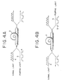
- FIG. 4A is for describing the principle of the present invention in the case where the signal light beam and the pumping light beam are propagated in the same direction through a rare-earth-doped fiber
- FIG. 4B is for describing the same in the case where the signal light beam and the pumping light beam are propagated in the directions opposite to each other through a rare-earth-doped fiber.
- the system of the present invention is such that, in a optical communication system provided with an optical fiber amplifier for amplifying a signal light beam 4 by having the signal light beam 4 and a pumping light beam 6 propagated through a rare-earth-doped fiber 2 doped with a rare earth element, the pumping light beam 6 is modulated by a high-frequency modulating signal 8 with a period shorter than the life span of fluorescence resulting from an excited state or thereabout, whereby transmission of information with the pumping light beam 6 acting as the carrier, in addition to transmission of information with the signal light beam 4, is made achievable.
- the rare-earth-doped fiber doped with a rare earth element has, as described above, a wide meaning that covers general waveguide structures such as waveguides doped with a rare earth element. Therefore, an optical fiber amplifier achieving amplification of a signal light beam by propagating the signal light beam together with a pumping light beam through a rare-earth-doped fiber doped with a rare earth element covers not only optical amplifiers which use optical fibers as propagating media of light but also optical amplifiers using optical waveguide structures such as optical waveguides as propagating media of light.
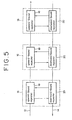
- FIG. 5 is an explanatory drawing of an optical repeater unit with the present invention applied thereto.
- the drawing shows a system of a two-way optical transmission lines formed of an upward-bound optical transmission line 12 and a downward-bound optical transmission line 14 with a single or a plurality (three in the illustrated case) of optical repeater units 16 provided in the way of the two-way optical transmission lines.
- the optical repeater unit 16 includes an upward-bound repeater 18 connected with the upward-bound optical transmission line 12 and a downward-bound repeater 20 connected with the downward-bound optical transmission line 14.
- These upward-bound repeater 18 and downward-bound repeater 20 perform communication of supervisory information therebetween for achieving a supervisory control function for the optical repeater unit in addition to general repeater functions.
- While the communication of the supervisory information between the upward-bound and down-ward bound repeaters 18 and 20 is achieved by means of electric signals, the transmission of supervisory information through the optical transmission lines 12 and 14 is achieved by means of pumping light beams propagated through rare-earth-doped fibers included in the optical repeater unit 16.
- FIG. 6 is a block diagram of the upward-bound repeater 18.
- the downward-bound repeater 20 has the same block structure as the upward-bound repeater 18.
- the wavelength of the signal light beam propagated through the upward-bound optical transmission line 12 is 1.536 ⁇ m, or 1.552 ⁇ m, for example, and the wavelength of the pumping light beam is 1.49 ⁇ m, for example.
- the portion of the pumping light beam which has not contributed to the optical amplification arrives at an upward-bound repeater 18.
- the signal light beam and the pumping light beam are split by an optical coupler 21 into portions in the ratio of 1:100, for example.
- the smaller split portion of the beams is input to an input signal level detector 22 for level detection of the signal light beam.
- the larger split portion of the beams is input to an optical fiber amplifier 24.
- the optical fiber amplifier 24 comprises a dichroic coupler 26 and a rare-earth-doped fiber 28 with its core doped with erbium.
- the dichroic coupler 26 splits the beams from the optical coupler 21 into the signal light beam and the pumping light beam, and leads the signal light beam into the rare-earth-doped fiber 28 and the pumping light beam to a receiver 32.
- the dichroic coupler 26 further reflects a pumping light beam from a pumping light source 30 and leads it into the rare-earth-doped fiber 28.
- the signal light beam amplified by the optical fiber amplifier 24 and the portion of the pumping light beam not consumed in the amplification of the signal light beam together are input to an optical coupler 36 through an optical isolator 34.
- the optical isolator 34 is provided for preventing oscillation from occurring due to gain of the rare-earth-doped fiber 28 as the result of formation of a resonator structure in the optical path including the rare-earth-doped fiber 28.
- the optical coupler 36 splits the input signal light beam and pumping light beam into portions in the ratio of 1:100, of which the larger split portion of the beams is reintroduced into the upward-bound optical transmission line 12 and the smaller split portion of the beams is input to an output signal level detector 38.
- the output signal level detector 38 suppresses the pumping light beam by means of an optical filter incorporated therein and detects the level of the amplified signal light beam.
- the pumping light source 30 is constituted of a semiconductor laser in the present embodiment and the intensity of the pumping light beam output therefrom or the average value thereof is controlled so that the level of the above described output signal may become constant by means of an APC circuit 40 depending on the signal output from the output signal level detector 38.
- the described control it becomes possible to have the signal light beam held at a constant level output from the upward-bound repeater 18 at all times regardless of the level of the signal light beam input to the upward-bound repeater 18.
- the input signal level from the input signal level detector 22, the output signal level from the output signal level detector 38, the pumping current (the bias current for the semiconductor laser) in the pumping light source 30, and the pumping light output from the same are delivered to the downward-bound repeater 20 as upward-bound supervisory information, which is delivered to the downward-bound optical transmission line 14 by modulating the pumping light beam there (also refer to FIG. 5).
- downward-bound supervisory information is accepted by the upward-bound repeater 18 through a signal processor 44 and the pumping light beam from the pumping light source 30 is modulated by the downward-bound supervisory information, whereby the downward-bound supervisory information is transmitted through the upward-bound optical transmission line 12.
- a delivery command of the downward-bound supervisory information to the upward-bound repeater 18 is received by the receiver 32 of the upward-bound repeater and, thereupon, the receiver 32 decodes the command and inform a controller 46 of the decoded command.
- This decoding can be achieved by subjecting the address information received by the receiver 32 to detection performed in an agreement detector 42, as to whether it is in agreement with the address information stored therein in advance.
- the controller 46 upon receipt of the delivery command of the supervisory information, controls a modulating circuit 48 depending on the downward-bound supervisory information from the signal processor 44 and, thereby, the pumping light beam from the pumping light source 30 is intensity-modulated, for example.
- the modulation speed at this time to be sufficiently higher than the reciprocal of the life span of the fluorescence in the rare-earth-doped fiber 28, even if the pumping light beam from the pumping light source 30 is modulated, the modulation component hardly appears in the signal light beam amplified in and delivered from the upward-bound repeater 18.
- both the sets of address information are not in agreement in the agreement detector 42 and, therefore, there is no necessity for delivering the downward-bound supervisory information to the upward-bound optical transmission line 12, it is arranged such that the supervisory information carried by the pumping light beam accepted from the preceding stage by the receiver 32 is reproduced and amplified by the controller 46 and the thus obtained information is used for modulating the pumping light source 30.
- FIG. 7 is a block diagram showing an arrangement of a two-way transmission system with the present invention applied thereto.
- This system has a first terminal station 50 and second terminal station 52 connected through a single optical fiber 54 to achieves the two-way transmission.
- the first terminal station 50 comprises a transmission portion 56 for transmitting a signal light beam of 1.55 ⁇ m band, a reception portion for receiving a modulated pumping light beam of 1.49 ⁇ m band, and a dichroic coupler 58.
- the second terminal station 52 comprises a preamplifier 62, a reception portion 64 for receiving the signal light beam of 1.55 ⁇ m band, and a transmission portion 66 for modulating and transmitting the pumping light beam of 1.49 ⁇ m band.
- the transmission portion 66 includes a pumping light source 68 and a modulating circuit 70 for intensity-modulating the semiconductor laser of the pumping light source 68.
- the preamplifier 62 includes a rare-earth-doped fiber 72 connected with the optical fiber 54 and a dichroic coupler 74 for both leading the modulated pumping light beam into the rare-earth-doped fiber 72 and delivering the signal light beam amplified by the rare-earth-doped fiber 72 to the reception portion 64.
- the signal light beam from the transmission portion 56 of the first terminal station 50 is delivered to the optical fiber 54 through the dichroic coupler 58 and, then, amplified by the preamplifier 62 of the second terminal station 52 and received by the reception portion 64.
- the reception sensitivity is enhanced.
- the modulated pumping light beam delivered from the transmission portion 66 of the second terminal station 52 contributes to the amplification of the signal light beam from the first terminal station 50 producing no effect of its modulated state on the signal light beam and, then, it is transmitted to the first terminal station 50 through the optical fiber 54 and accepted by the reception portion 60 so that the transmitted information is reproduced therein.
- the two-way transmission is achieved by the transmission of information with the signal light beam and by the transmission of information with the pumping light beam acting as the carrier.
- the modulation of the pumping light source 68 in the transmission portion 66 of the second terminal station 52 is performed, the same as in the embodiment described with reference to FIG. 5 and FIG. 6, by a high-frequency modulating signal having a period shorter than the life span of fluorescence resulting from the excited state in the rare-earth-doped fiber or thereabout.
- the life span of fluorescence resulting from the excited state is approximately 14 ms, for example, and, hence, a practically sufficient transmission capacity can be obtained.
Claims (7)
- Amplificateur optique servant à amplifier un signal optique, comprenant:caractérisé en ce queune fibre optique (28; 54) dopée par un élément de terre rare, possédant une extrémité d'entrée, dans lequel le signal optique est introduit, et une extrémité de sortie; etune source de lumière de pompage (30; 68) émettant un faisceau de lumière de pompage devant être introduit à l'extrémité d'entrée ou à l'extrémité de sortie de ladite fibre optique;le signal optique étant amplifié par propagation dans ladite fibre optique;
ladite source de lumière de pompage est prévue pour délivrer une information de contrôle. - Amplificateur optique selon la revendication 1, caractérisé en ce que l'information de contrôle est dérivée d'un second faisceau de lumière émis par ladite source de lumière de pompage.
- Amplificateur optique selon la revendication 1, caractérisé en ce queladite source de lumière de pompage est un laser à semiconducteurs; etl'information de contrôle est dérivée d'un courant de polarisation dudit laser à semiconducteurs.
- Amplificateur optique selon l'une quelconque des revendications précédentes, caractérisé en ce que ledit signal optique, qui est amplifiée par propagation dans ladite fibre optique, est délivré par l'extrémité de sortie de ladite fibre optique.
- Système de transmission optique comprenantun amplificateur optique selon l'une quelconque des revendications précédentes; etune station de réception (21; 50) pour transmettre le signal optique à l'amplificateur par l'intermédiaire d'une ligne de transmission optique.
- Système de transmission optique selon la revendication 5, comprenant en outre une station de réception pour recevoir le signal optique de la part de l'amplificateur optique par l'intermédiaire de la ligne de transmission optique.
- Procédé pour amplifier un signal optique, comprenant:caractérisé en ce qu'il comporte en outreune étape consistant à émettre, à partir d'une faible lumière de pompage, un faisceau de lumière de pompage devant être introduit à une extrémité d'entrée ou à une extrémité de sortie d'une fibre optique dopée par un élément de terre rare;
une étape pour délivrer une information de contrôle à partir de la source de lumière de pompage.
Applications Claiming Priority (4)
| Application Number | Priority Date | Filing Date | Title |
|---|---|---|---|
| JP01223172A JP3137632B2 (ja) | 1989-08-31 | 1989-08-31 | 光ファイバ増幅器を備えた光通信方式 |
| JP22317289 | 1989-08-31 | ||
| EP95107617A EP0675610A1 (fr) | 1989-08-31 | 1990-08-31 | Amplificateur optique et système de communication optique pourvu de l'amplificateur optique |
| EP90116755A EP0415438B1 (fr) | 1989-08-31 | 1990-08-31 | Amplificateur optique et système de communication optique pourvu de l'amplificateur optique |
Related Parent Applications (1)
| Application Number | Title | Priority Date | Filing Date |
|---|---|---|---|
| EP95107617A Division EP0675610A1 (fr) | 1989-08-31 | 1990-08-31 | Amplificateur optique et système de communication optique pourvu de l'amplificateur optique |
Publications (3)
| Publication Number | Publication Date |
|---|---|
| EP1063795A2 EP1063795A2 (fr) | 2000-12-27 |
| EP1063795A3 EP1063795A3 (fr) | 2001-03-14 |
| EP1063795B1 true EP1063795B1 (fr) | 2002-09-18 |
Family
ID=16793932
Family Applications (6)
| Application Number | Title | Priority Date | Filing Date |
|---|---|---|---|
| EP90116755A Expired - Lifetime EP0415438B1 (fr) | 1989-08-31 | 1990-08-31 | Amplificateur optique et système de communication optique pourvu de l'amplificateur optique |
| EP95107617A Withdrawn EP0675610A1 (fr) | 1989-08-31 | 1990-08-31 | Amplificateur optique et système de communication optique pourvu de l'amplificateur optique |
| EP95107616A Expired - Lifetime EP0669730B1 (fr) | 1989-08-31 | 1990-08-31 | Amplificateur optique et système de communication optique pourvu de l'amplificateur optique |
| EP95107618A Expired - Lifetime EP0674403B1 (fr) | 1989-08-31 | 1990-08-31 | Amplificateur optique et système de communication optique pourvu de l'amplificateur optique |
| EP95107627A Expired - Lifetime EP0676871B1 (fr) | 1989-08-31 | 1990-08-31 | Amplificateur optique et système de communication optique pourvue d'amplificateur optique |
| EP00121344A Expired - Lifetime EP1063795B1 (fr) | 1989-08-31 | 1990-08-31 | Amplificateur optique, système de transmission optique comportant un amplificateur optique et procédé d'amplification d'un signal optique |
Family Applications Before (5)
| Application Number | Title | Priority Date | Filing Date |
|---|---|---|---|
| EP90116755A Expired - Lifetime EP0415438B1 (fr) | 1989-08-31 | 1990-08-31 | Amplificateur optique et système de communication optique pourvu de l'amplificateur optique |
| EP95107617A Withdrawn EP0675610A1 (fr) | 1989-08-31 | 1990-08-31 | Amplificateur optique et système de communication optique pourvu de l'amplificateur optique |
| EP95107616A Expired - Lifetime EP0669730B1 (fr) | 1989-08-31 | 1990-08-31 | Amplificateur optique et système de communication optique pourvu de l'amplificateur optique |
| EP95107618A Expired - Lifetime EP0674403B1 (fr) | 1989-08-31 | 1990-08-31 | Amplificateur optique et système de communication optique pourvu de l'amplificateur optique |
| EP95107627A Expired - Lifetime EP0676871B1 (fr) | 1989-08-31 | 1990-08-31 | Amplificateur optique et système de communication optique pourvue d'amplificateur optique |
Country Status (5)
| Country | Link |
|---|---|
| US (6) | US5299048A (fr) |
| EP (6) | EP0415438B1 (fr) |
| JP (1) | JP3137632B2 (fr) |
| CA (1) | CA2024345C (fr) |
| DE (5) | DE69029072T2 (fr) |
Families Citing this family (110)
| Publication number | Priority date | Publication date | Assignee | Title |
|---|---|---|---|---|
| JP3137632B2 (ja) * | 1989-08-31 | 2001-02-26 | 富士通株式会社 | 光ファイバ増幅器を備えた光通信方式 |
| US5229876A (en) * | 1990-03-26 | 1993-07-20 | At&T Bell Laboratories | Telemetry for optical fiber amplifier repeater |
| GB2245120B (en) * | 1990-06-16 | 1994-03-30 | Stc Plc | Telemetry |
| GB2245122B (en) * | 1990-06-16 | 1994-08-03 | Stc Plc | Telemetry |
| GB2245121B (en) * | 1990-06-16 | 1994-03-16 | Stc Plc | Telemetry |
| DE4036327A1 (de) * | 1990-11-15 | 1992-05-21 | Standard Elektrik Lorenz Ag | Optisches nachrichtenuebertragungssystem mit einem faseroptischen verstaerker |
| US5268786A (en) * | 1991-03-15 | 1993-12-07 | Mitsubishi Denki Kabushiki Kaisha | Optical fiber amplifier and its amplification method |
| FR2674392B1 (fr) * | 1991-03-22 | 1994-09-30 | Cit Alcatel | Systeme de transmission de signaux auxiliaires sur une liaison optique. |
| DE4109683A1 (de) * | 1991-03-23 | 1992-09-24 | Standard Elektrik Lorenz Ag | System fuer optische signaluebertragung, insbesondere optisches kabelfernsehsystem, mit ueberwachungs- und dienstkanaleinrichtung |
| IT1247845B (it) * | 1991-03-29 | 1995-01-02 | Pirelli Cavi Spa | Linea di telecomunicazione a fibre ottiche con dispositivo di protezione per amplificatori ottici |
| JPH04326823A (ja) * | 1991-04-26 | 1992-11-16 | Oki Electric Ind Co Ltd | 光増幅中継器の監視装置及び監視方法 |
| DE69228087T2 (de) * | 1991-05-27 | 1999-08-05 | Furukawa Electric Co Ltd | Optischer Verstärker |
| EP0652613B1 (fr) * | 1991-11-08 | 1999-02-03 | Mitsubishi Denki Kabushiki Kaisha | Amplificateur à fibre optique |
| US5455704A (en) * | 1991-11-08 | 1995-10-03 | Mitsubishi Denki Kabushiki Kaisha | Optical-fiber light amplifier |
| JPH05292040A (ja) * | 1992-04-08 | 1993-11-05 | Hitachi Ltd | 光伝送システムの構築方法 |
| US5500756A (en) * | 1992-02-28 | 1996-03-19 | Hitachi, Ltd. | Optical fiber transmission system and supervision method of the same |
| JP2620451B2 (ja) * | 1992-03-06 | 1997-06-11 | 日本電信電話株式会社 | 光増幅器 |
| US5555477A (en) * | 1992-04-08 | 1996-09-10 | Hitachi, Ltd. | Optical transmission system constructing method and system |
| US5383046A (en) * | 1992-05-29 | 1995-01-17 | Fujitsu Limited | Supervisory and control signal transmitting system for use in optically amplifying repeaters system |
| US5463488A (en) * | 1992-07-31 | 1995-10-31 | At&T Ipm Corp. | Distribution of clock signals by pump power modulation in an optically amplified network |
| DE4239187A1 (de) * | 1992-11-21 | 1994-05-26 | Sel Alcatel Ag | System zur optischen Nachrichtenübertragung mit faseroptischen Verstärkern und einer Einrichtung zum Überprüfen der Übertragungswege |
| DE4310292A1 (de) * | 1993-03-30 | 1994-10-06 | Sel Alcatel Ag | Faseroptischer Verstärker mit einer Vorrichtung zu Überwachung der Eingangsleistung |
| FR2703531B1 (fr) * | 1993-03-30 | 1995-05-19 | Cit Alcatel | Dispositif d'évaluation de la qualité de transmission d'un équipement amplificateur optique. |
| US5436750A (en) * | 1993-05-07 | 1995-07-25 | Nec Corporation | Optical repeatered transmission with fault locating capability |
| JP2546152B2 (ja) * | 1993-06-15 | 1996-10-23 | 日本電気株式会社 | 光変調増幅器 |
| DE4321856A1 (de) * | 1993-07-01 | 1995-01-12 | Sel Alcatel Ag | Faseroptischer Verstärker mit einer Vorrichtung zur Überwachung der Pump- und Eingangsleistung |
| JP3247919B2 (ja) * | 1993-07-19 | 2002-01-21 | 三菱電機株式会社 | 光増幅装置 |
| GB2280560B (en) * | 1993-07-31 | 1997-09-03 | Northern Telecom Ltd | Communications system |
| JPH0795160A (ja) * | 1993-09-20 | 1995-04-07 | Fujitsu Ltd | 光増幅器の応答信号変調方法 |
| JP3012760B2 (ja) * | 1993-10-25 | 2000-02-28 | 三菱電機株式会社 | 光増幅器及び分配システム及びローカル・エリア・ネットワーク及び利得制御方法 |
| JP2551371B2 (ja) * | 1993-12-01 | 1996-11-06 | 日本電気株式会社 | 光中継器 |
| JP2697587B2 (ja) * | 1993-12-16 | 1998-01-14 | 日本電気株式会社 | 光増幅器の監視回路 |
| US5481391A (en) * | 1994-02-17 | 1996-01-02 | At&T Corp. | Optical fiber system and method for overcoming the effects of polarization gain anisotropy in a fiber amplifier |
| JP3353047B2 (ja) * | 1994-05-25 | 2002-12-03 | 安藤電気株式会社 | 光増幅器 |
| FR2721158B1 (fr) * | 1994-06-14 | 1996-07-12 | Alcatel Submarcom | Système de transmission sur une ligne à fibre optique sans répéteur, avec amplifications distante et locale. |
| JPH0832162A (ja) * | 1994-07-15 | 1996-02-02 | Sumitomo Electric Ind Ltd | 光増幅器 |
| US5574589A (en) * | 1995-01-09 | 1996-11-12 | Lucent Technologies Inc. | Self-amplified networks |
| US5563731A (en) * | 1995-02-22 | 1996-10-08 | Nec Corporation | Monitor control signal receiving apparatus for optical fiber amplifier |
| JP3442897B2 (ja) * | 1995-03-08 | 2003-09-02 | Kddi株式会社 | 範囲別利得制御光増幅器及び範囲別光増幅器利得制御方法及び光受信器及び光中継器 |
| JP3587580B2 (ja) * | 1995-03-17 | 2004-11-10 | 富士通株式会社 | 光増幅中継器の入力モニタシステム |
| US5657153A (en) * | 1995-03-21 | 1997-08-12 | Sdl, Inc. | Optical amplifier with complementary modulation signal inputs |
| US5539570A (en) * | 1995-03-21 | 1996-07-23 | Nec Corporation | Monitoring state of optical elements in an optical amplifier |
| JP3072047B2 (ja) * | 1995-03-22 | 2000-07-31 | 株式会社東芝 | 波長多重光伝送装置および光中継器 |
| JP3512264B2 (ja) | 1995-05-08 | 2004-03-29 | 富士通株式会社 | 光増幅装置 |
| US5532864A (en) * | 1995-06-01 | 1996-07-02 | Ciena Corporation | Optical monitoring channel for wavelength division multiplexed optical communication system |
| FI954809A (fi) * | 1995-10-09 | 1997-04-10 | Nokia Telecommunications Oy | Ylläpitosanomien välittäminen kuituvahvistimelta |
| JPH09252286A (ja) * | 1996-03-15 | 1997-09-22 | Nec Corp | 光ファイバアンプ中継器 |
| JPH10164026A (ja) * | 1996-10-04 | 1998-06-19 | Oki Electric Ind Co Ltd | 光中継装置と光伝送システム |
| EP0964487B1 (fr) | 1997-02-25 | 2008-09-03 | Hitachi, Ltd. | Dispositif d'interconnexion optique |
| US6452701B1 (en) * | 1997-03-19 | 2002-09-17 | Fujitsu Limited | Wavelength division multiplexing communications network supervisory system |
| US6211985B1 (en) * | 1997-08-08 | 2001-04-03 | Tyco Submarine Systems Ltd. | Remote monitoring of an optical transmission system using line monitoring signals |
| US6141440A (en) * | 1998-06-04 | 2000-10-31 | Canon Kabushiki Kaisha | Disparity measurement with variably sized interrogation regions |
| US6411407B1 (en) | 1998-09-17 | 2002-06-25 | Alcatel | Method for providing a bidirectional optical supervisory channel |
| US6384948B1 (en) | 1998-09-30 | 2002-05-07 | The United States Of America As Represented By The Secretary Of The Navy | High-sensitivity, high-speed digital optical photoreceiver |
| US6721508B1 (en) | 1998-12-14 | 2004-04-13 | Tellabs Operations Inc. | Optical line terminal arrangement, apparatus and methods |
| KR100301950B1 (ko) * | 1999-04-02 | 2001-10-29 | 윤덕용 | 광 회선분배 시스템의 입력단자 판별에 의한 광 경로 감시 장치 |
| DE69941306D1 (de) * | 1999-10-29 | 2009-10-01 | Fujitsu Ltd | Optische übertragungsvorrichtung und optische zwischenverstärkungsvorrichtung |
| JP2002050816A (ja) * | 2000-08-02 | 2002-02-15 | Fujitsu Ltd | 光増幅器 |
| US6414788B1 (en) * | 2000-10-02 | 2002-07-02 | Onetta, Inc. | Optical amplifier system with transient control |
| US6437906B1 (en) | 2000-11-22 | 2002-08-20 | Cisco Technology, Inc. | All-optical gain controlled L-band EDFA structure with reduced four-wave mixing cross-talk |
| US6373621B1 (en) * | 2001-01-18 | 2002-04-16 | Nortel Networks Limited | Method and apparatus for safer operation of raman amplifiers |
| US7277636B1 (en) * | 2001-01-26 | 2007-10-02 | Gazdzinski Robert F | Optical communication apparatus and methods using pulses having modified propagation speeds |
| DE10109130B4 (de) * | 2001-02-24 | 2015-02-19 | Carl Zeiss Microscopy Gmbh | Verfahren zur Aufzeichnung und Darstellung von Fluoreszenzbildern mit hoher räumlicher Auflösung |
| GB2374457A (en) * | 2001-04-09 | 2002-10-16 | Bookham Technology Plc | Hybridised Fibre Amplifier/Waveguide Structures |
| EP1391063A1 (fr) * | 2001-04-30 | 2004-02-25 | PIRELLI SUBMARINE TELECOM SYSTEMS ITALIA S.p.A. | Systeme de transmission optique comportant un systeme de supervision |
| JP4647147B2 (ja) * | 2001-07-16 | 2011-03-09 | 富士通株式会社 | ラマン増幅を用いた光伝送方法および光伝送システム |
| JP4467213B2 (ja) * | 2001-08-14 | 2010-05-26 | 富士通株式会社 | 光伝送システム |
| US6914716B2 (en) * | 2001-11-21 | 2005-07-05 | Lucent Technologies Inc. | Modulated pump source for fiber Raman amplifier |
| DE60132259D1 (de) * | 2001-12-27 | 2008-02-14 | Pirelli Submarine Telecom Systems Italia Spa | Optisches übertragungssystem mit raman-verstärkern umfassend ein überwachungssystem |
| EP1461877B1 (fr) * | 2001-12-27 | 2008-01-23 | PIRELLI SUBMARINE TELECOM SYSTEMS ITALIA S.p.A. | Systeme de transmission optique a l'aide d'amplificateurs raman comprenant un systeme de commande |
| US6748136B2 (en) * | 2002-03-15 | 2004-06-08 | Fitel Usa Corp. | Wide band Raman amplifiers |
| AU2003222112A1 (en) * | 2002-03-28 | 2003-10-13 | Celion Networks, Inc. | Apparatus and method for aggregation and transportation for plesiosynchronous framing oriented data formats |
| WO2003084082A2 (fr) | 2002-03-29 | 2003-10-09 | Celion Networks, Inc. | Systeme de transmission optique a terminaux repartis |
| US7164692B2 (en) | 2002-04-08 | 2007-01-16 | Jeffrey Lloyd Cox | Apparatus and method for transmitting 10 Gigabit Ethernet LAN signals over a transport system |
| US6965738B2 (en) * | 2002-04-16 | 2005-11-15 | Eiselt Michael H | Chromatic dispersion compensation system and method |
| WO2003090035A2 (fr) * | 2002-04-22 | 2003-10-30 | Celion Networks, Inc. | Systeme de transport optique automatise |
| JP3833564B2 (ja) | 2002-04-24 | 2006-10-11 | 富士通株式会社 | ラマン増幅を用いた光ファイバ伝送のための方法及び装置 |
| US6847678B2 (en) * | 2002-04-25 | 2005-01-25 | Raytheon Company | Adaptive air interface waveform |
| US7711271B2 (en) * | 2002-04-30 | 2010-05-04 | Eiselt Michael H | Wave division multiplexed optical transport system utilizing optical circulators to isolate an optical service channel |
| US7206516B2 (en) * | 2002-04-30 | 2007-04-17 | Pivotal Decisions Llc | Apparatus and method for measuring the dispersion of a fiber span |
| US8494372B2 (en) * | 2002-04-30 | 2013-07-23 | Pivotal Decisions Llc | Apparatus and method for optimizing optical and electrical filtering of optical signals |
| US7460296B2 (en) * | 2002-04-30 | 2008-12-02 | Pivotal Decisions Llc | Compensation for spectral power tilt from scattering |
| WO2003094398A1 (fr) * | 2002-04-30 | 2003-11-13 | Celion Networks, Inc. | Architecture de systeme de transport optique pour connexion de terminal distant |
| DE60307464T2 (de) * | 2002-05-30 | 2007-03-15 | Fujitsu Ltd., Kawasaki | Verstärker für optische netzwerke und verfahren |
| US7085496B2 (en) * | 2002-05-30 | 2006-08-01 | Fujitsu Limited | Passive add/drop amplifier for optical networks and method |
| US7075712B2 (en) | 2002-05-30 | 2006-07-11 | Fujitsu Limited | Combining and distributing amplifiers for optical network and method |
| US7460745B2 (en) * | 2002-06-04 | 2008-12-02 | Pivotal Decisions Llc | Configurable dispersion compensation trimmer |
| US7440164B2 (en) * | 2002-06-04 | 2008-10-21 | Pivotal Decisions Llc | Apparatus and method for Raman gain spectral control |
| AU2003273529A1 (en) * | 2002-06-04 | 2003-12-19 | Celion Networks, Inc. | Flexible, dense line card architecture |
| US20040042067A1 (en) * | 2002-06-04 | 2004-03-04 | Eiselt Michael H. | Apparatus and method for duplex optical transport using a co-directional optical amplifier |
| US20050226630A1 (en) * | 2003-06-03 | 2005-10-13 | Celion Networks Inc. | Optical bypass method and architecture |
| US6920277B2 (en) | 2002-06-04 | 2005-07-19 | Marvin R. Young | Optical bypass method and architecture |
| US7924496B2 (en) * | 2002-06-04 | 2011-04-12 | Pivotal Decisions Llc | Apparatus and method for Raman gain control |
| US7603042B2 (en) * | 2002-06-04 | 2009-10-13 | Eiselt Michael H | Apparatus and method for optimum decision threshold setting |
| US20040017603A1 (en) * | 2002-07-29 | 2004-01-29 | Paul Jay | Optical amplifier controller |
| US7421207B2 (en) * | 2002-12-13 | 2008-09-02 | Pivotal Decisions Llc | Single fiber duplex optical transport |
| US7656905B2 (en) | 2002-12-24 | 2010-02-02 | Samir Sheth | Apparatus and method for aggregation and transportation of gigabit ethernet and other packet based data formats |
| US7782778B2 (en) * | 2002-12-24 | 2010-08-24 | Samir Satish Sheth | Apparatus and method for fibre channel distance extension embedded within an optical transport system |
| US6898347B2 (en) * | 2003-05-30 | 2005-05-24 | Intel Corporation | Monitoring power in optical networks |
| US7158289B1 (en) | 2003-11-07 | 2007-01-02 | Alcatel | Method and apparatus for implementing optical supervisory channel using broadband noise modulation |
| US7193839B2 (en) * | 2004-04-13 | 2007-03-20 | James Scott Hacsi | Methods of storing and retrieving electric energy |
| US7471900B2 (en) | 2004-12-08 | 2008-12-30 | Electronics And Telecommunications Research Institute | Passive optical network system and method of transmitting broadcasting signal in same |
| US7440172B2 (en) * | 2005-06-23 | 2008-10-21 | Viscore Technologies Inc. | Optical amplifier |
| US20070014514A1 (en) * | 2005-06-23 | 2007-01-18 | Viscore Technologies Inc. | Optical component |
| JP4648263B2 (ja) * | 2006-07-21 | 2011-03-09 | 株式会社日立製作所 | 光増幅器および光伝送装置 |
| JP5699760B2 (ja) * | 2011-04-04 | 2015-04-15 | 富士通株式会社 | 光増幅装置、光増幅装置の制御方法、光受信局及び光伝送システム |
| TW201348775A (zh) * | 2012-05-22 | 2013-12-01 | Hon Hai Prec Ind Co Ltd | 雙向雙頻光傳輸模組及其傳輸組件 |
| US10419066B1 (en) * | 2017-10-05 | 2019-09-17 | Harmonic, Inc. | Remote radio frequency (RF) AGC loop |
| GB201719629D0 (en) * | 2017-11-24 | 2018-01-10 | Spi Lasers Uk Ltd | Apparatus for providing optical radiation |
| US20210044077A1 (en) * | 2018-03-07 | 2021-02-11 | Nec Corporation | Monitoring apparatus for optical amplifier, optical amplifying system, and method of monitoring amplified optical signal |
Family Cites Families (45)
| Publication number | Priority date | Publication date | Assignee | Title |
|---|---|---|---|---|
| JPS52155901A (en) * | 1976-06-21 | 1977-12-24 | Nippon Telegr & Teleph Corp <Ntt> | Transmission system for optical fiber |
| JPS55155901A (en) * | 1979-05-21 | 1980-12-04 | Nippon Kiki Kogyo Kk | Multistage fluid cylinder device |
| JPS56144416A (en) * | 1980-04-14 | 1981-11-10 | Nippon Telegr & Teleph Corp <Ntt> | Light signal amplifier |
| JPS56144415A (en) * | 1980-04-14 | 1981-11-10 | Nippon Telegr & Teleph Corp <Ntt> | Light signal amplifier |
| JPS56165437A (en) * | 1980-05-26 | 1981-12-19 | Kokusai Denshin Denwa Co Ltd <Kdd> | Optical repeating system for optical communication |
| JPS6037639B2 (ja) * | 1980-12-12 | 1985-08-27 | 日本電信電話株式会社 | 光信号増幅器 |
| JPS5848513A (ja) * | 1981-09-18 | 1983-03-22 | Nec Corp | 波形整形光増幅装置 |
| JPS5853243A (ja) * | 1981-09-25 | 1983-03-29 | Nippon Telegr & Teleph Corp <Ntt> | 光伝送方式 |
| JPS5885588A (ja) * | 1981-11-16 | 1983-05-21 | Nec Corp | 波長多重光増幅装置 |
| JPS58115948A (ja) * | 1981-12-29 | 1983-07-09 | Nec Corp | 双方向光増幅器 |
| JPS58119241A (ja) * | 1982-01-08 | 1983-07-15 | Nec Corp | 光信号検出装置 |
| JPS59101629A (ja) * | 1982-12-01 | 1984-06-12 | Nec Corp | ファイバ内光増幅装置 |
| JPS59126696A (ja) * | 1983-01-10 | 1984-07-21 | Nec Corp | 光通信用光増幅装置 |
| US4674830A (en) * | 1983-11-25 | 1987-06-23 | The Board Of Trustees Of The Leland Stanford Junior University | Fiber optic amplifier |
| US4723824A (en) * | 1983-11-25 | 1988-02-09 | The Board Of Trustees Of The Leland Stanford Junior University | Fiber optic amplifier |
| JPS6175326A (ja) * | 1984-09-21 | 1986-04-17 | Nec Corp | フアイバ内光増幅送信装置 |
| EP0228435B1 (fr) * | 1985-06-19 | 1990-09-19 | BRITISH TELECOMMUNICATIONS public limited company | Systeme de communication optique |
| US4712075A (en) * | 1985-11-27 | 1987-12-08 | Polaroid Corporation | Optical amplifier |
| GB8613192D0 (en) * | 1986-05-30 | 1986-07-02 | British Telecomm | Optical resonating device |
| JPS63200632A (ja) * | 1987-02-16 | 1988-08-18 | Hamamatsu Photonics Kk | 宇宙光通信装置 |
| JPH01217424A (ja) * | 1988-02-26 | 1989-08-31 | Fujitsu Ltd | ファイバラマン増幅光通信方式 |
| US4881790A (en) * | 1988-04-25 | 1989-11-21 | American Telephone And Telegraph Company, At&T Bell Laboratories | Optical communications system comprising raman amplification means |
| JPH0758376B2 (ja) * | 1988-05-26 | 1995-06-21 | 浜松ホトニクス株式会社 | 光波形整形装置 |
| US5282079A (en) * | 1988-06-10 | 1994-01-25 | Pirelli General Plc | Optical fibre amplifier |
| GB8813769D0 (en) * | 1988-06-10 | 1988-07-13 | Pirelli General Plc | Optical fibre |
| FR2638854B1 (fr) * | 1988-11-10 | 1992-09-04 | Comp Generale Electricite | Amplificateur laser a fibre optique dopee |
| JP2546711B2 (ja) * | 1988-12-22 | 1996-10-23 | 国際電信電話株式会社 | Erドープ光ファイバレーザ素子 |
| US5008887A (en) * | 1989-04-19 | 1991-04-16 | Kafka James D | Mode-locked fiber laser |
| US5204923A (en) * | 1989-07-17 | 1993-04-20 | Pirelli Cavi S.P.A. | Unit for amplifying light signals in optical fiber transmission lines |
| US5210808A (en) * | 1989-07-17 | 1993-05-11 | Pirelli Cavi S.P.A. | Unit for amplifying light signals in optical fiber transmission lines |
| IT1231379B (it) * | 1989-07-21 | 1991-12-02 | Pirelli Cavi Spa | Linea di telecomunicazioni a fibre ottiche incorporante amplificatori dei segnali trasmessi ed amplificatori per detta linea |
| US4963832A (en) * | 1989-08-08 | 1990-10-16 | At&T Bell Laboratories | Erbium-doped fiber amplifier coupling device |
| JPH0373934A (ja) * | 1989-08-15 | 1991-03-28 | Fujitsu Ltd | 光増幅器 |
| JP3137632B2 (ja) * | 1989-08-31 | 2001-02-26 | 富士通株式会社 | 光ファイバ増幅器を備えた光通信方式 |
| US5005175A (en) * | 1989-11-27 | 1991-04-02 | At&T Bell Laboratories | Erbium-doped fiber amplifier |
| US5229876A (en) * | 1990-03-26 | 1993-07-20 | At&T Bell Laboratories | Telemetry for optical fiber amplifier repeater |
| US5052142A (en) * | 1990-07-16 | 1991-10-01 | Mikus Edward M | Safety lock for revolvers |
| US5233463A (en) * | 1990-07-16 | 1993-08-03 | Pirelli Cavi S.P.A. | Active fiber optical amplifier for a fiber optics telecommunication line |
| JPH0475036A (ja) * | 1990-07-18 | 1992-03-10 | Nippon Telegr & Teleph Corp <Ntt> | 光増幅装置 |
| DE4036327A1 (de) * | 1990-11-15 | 1992-05-21 | Standard Elektrik Lorenz Ag | Optisches nachrichtenuebertragungssystem mit einem faseroptischen verstaerker |
| US5268786A (en) * | 1991-03-15 | 1993-12-07 | Mitsubishi Denki Kabushiki Kaisha | Optical fiber amplifier and its amplification method |
| JP3008667B2 (ja) * | 1992-05-07 | 2000-02-14 | 日本電気株式会社 | 光中継方式 |
| US5343320A (en) * | 1992-08-03 | 1994-08-30 | At&T Bell Laboratories | Pump laser control circuit for an optical transmission system |
| EP0593237B1 (fr) * | 1992-10-13 | 1997-12-29 | Nec Corporation | Amplificateur optique à semiconducteur |
| US5374973A (en) * | 1993-09-21 | 1994-12-20 | Alcatel Network Systems, Inc. | Optical amplifier |
-
1989
- 1989-08-31 JP JP01223172A patent/JP3137632B2/ja not_active Expired - Lifetime
-
1990
- 1990-08-30 CA CA002024345A patent/CA2024345C/fr not_active Expired - Lifetime
- 1990-08-31 EP EP90116755A patent/EP0415438B1/fr not_active Expired - Lifetime
- 1990-08-31 DE DE69029072T patent/DE69029072T2/de not_active Expired - Lifetime
- 1990-08-31 EP EP95107617A patent/EP0675610A1/fr not_active Withdrawn
- 1990-08-31 DE DE69033867T patent/DE69033867T2/de not_active Expired - Lifetime
- 1990-08-31 DE DE69034006T patent/DE69034006T2/de not_active Expired - Lifetime
- 1990-08-31 EP EP95107616A patent/EP0669730B1/fr not_active Expired - Lifetime
- 1990-08-31 DE DE69033858T patent/DE69033858T2/de not_active Expired - Lifetime
- 1990-08-31 EP EP95107618A patent/EP0674403B1/fr not_active Expired - Lifetime
- 1990-08-31 EP EP95107627A patent/EP0676871B1/fr not_active Expired - Lifetime
- 1990-08-31 EP EP00121344A patent/EP1063795B1/fr not_active Expired - Lifetime
- 1990-08-31 DE DE69033859T patent/DE69033859T2/de not_active Expired - Lifetime
-
1992
- 1992-12-08 US US07/987,568 patent/US5299048A/en not_active Expired - Lifetime
-
1994
- 1994-02-01 US US08/189,841 patent/US5546213A/en not_active Expired - Lifetime
-
1995
- 1995-03-08 US US08/400,755 patent/US5526163A/en not_active Expired - Lifetime
- 1995-03-08 US US08/400,762 patent/US5535050A/en not_active Expired - Lifetime
- 1995-03-08 US US08/400,761 patent/US5510931A/en not_active Expired - Lifetime
- 1995-03-08 US US08/400,760 patent/US5521737A/en not_active Expired - Lifetime
Also Published As
| Publication number | Publication date |
|---|---|
| DE69033859D1 (de) | 2001-12-20 |
| DE69034006T2 (de) | 2003-06-05 |
| JP3137632B2 (ja) | 2001-02-26 |
| US5521737A (en) | 1996-05-28 |
| CA2024345C (fr) | 1995-02-14 |
| EP0669730B1 (fr) | 2001-11-21 |
| DE69029072T2 (de) | 1997-04-03 |
| EP0415438B1 (fr) | 1996-11-06 |
| US5510931A (en) | 1996-04-23 |
| DE69034006D1 (de) | 2002-10-24 |
| EP0676871B1 (fr) | 2001-11-14 |
| US5526163A (en) | 1996-06-11 |
| DE69033858T2 (de) | 2002-06-13 |
| EP0669730A3 (fr) | 1995-09-20 |
| EP1063795A3 (fr) | 2001-03-14 |
| DE69033867T2 (de) | 2002-06-27 |
| US5546213A (en) | 1996-08-13 |
| DE69033859T2 (de) | 2002-06-13 |
| CA2024345A1 (fr) | 1991-03-01 |
| EP0415438A2 (fr) | 1991-03-06 |
| EP0675610A1 (fr) | 1995-10-04 |
| EP0669730A2 (fr) | 1995-08-30 |
| EP0415438A3 (en) | 1992-02-26 |
| JPH0387727A (ja) | 1991-04-12 |
| US5299048A (en) | 1994-03-29 |
| DE69033867D1 (de) | 2002-01-03 |
| EP0676871A1 (fr) | 1995-10-11 |
| EP0674403A1 (fr) | 1995-09-27 |
| DE69029072D1 (de) | 1996-12-12 |
| EP1063795A2 (fr) | 2000-12-27 |
| EP0674403B1 (fr) | 2001-11-14 |
| US5535050A (en) | 1996-07-09 |
| DE69033858D1 (de) | 2001-12-20 |
Similar Documents
| Publication | Publication Date | Title |
|---|---|---|
| EP1063795B1 (fr) | Amplificateur optique, système de transmission optique comportant un amplificateur optique et procédé d'amplification d'un signal optique | |
| JP3025210B2 (ja) | 光ファイバラマン増幅器を含む装置 | |
| US6178038B1 (en) | Optical amplifier having an improved noise figure | |
| KR100265788B1 (ko) | 높은소신호이득을갖는광섬유증폭기 | |
| JP2000151507A (ja) | 光伝送システム | |
| US20010012147A1 (en) | Optical fibre amplifier having a gain flattening filter | |
| CA2344115C (fr) | Propagation monomode et multimode simultanee de signaux dans une fibre optique a double gainage | |
| JPH09197452A (ja) | 光ファイバ通信方式 | |
| EP0599352B1 (fr) | Système d'amplification optique | |
| US5436751A (en) | Analog optical transmission system and optical fiber amplifier | |
| US5235604A (en) | Optical amplifier using semiconductor laser as multiplexer | |
| JP2846291B2 (ja) | 中間アイソレータ型光ファイバ増幅器および光ファイバ伝送システム | |
| JP3195237B2 (ja) | 光伝送装置、光通信システム及び入力光信号の増幅方法 | |
| KR100269170B1 (ko) | 광섬유 반사체를 이용한 광섬유증폭기 | |
| JP3193293B2 (ja) | 光伝送装置、光通信システム及び入力光信号の伝送方法 | |
| JP3153127B2 (ja) | 光伝送装置、光通信システム及び光信号を増幅する方法 | |
| JP2002111589A (ja) | 光伝送装置、光通信システム及び光信号の伝送方法 | |
| JPH08331060A (ja) | 光伝送装置、光通信システム及び光信号の伝送方法 | |
| JP2001189510A (ja) | 光ファイバアンプ | |
| JPH06302892A (ja) | 一定の偏光状態の光出力を得る為の光増幅装置 |
Legal Events
| Date | Code | Title | Description |
|---|---|---|---|
| PUAI | Public reference made under article 153(3) epc to a published international application that has entered the european phase |
Free format text: ORIGINAL CODE: 0009012 |
|
| AC | Divisional application: reference to earlier application |
Ref document number: 415438 Country of ref document: EP Ref document number: 675610 Country of ref document: EP |
|
| AK | Designated contracting states |
Kind code of ref document: A2 Designated state(s): DE FR GB |
|
| PUAL | Search report despatched |
Free format text: ORIGINAL CODE: 0009013 |
|
| AK | Designated contracting states |
Kind code of ref document: A3 Designated state(s): DE FR GB |
|
| RIN1 | Information on inventor provided before grant (corrected) |
Inventor name: SUYAMA, MASUO C/O FUJITSU LIMITED |
|
| 17P | Request for examination filed |
Effective date: 20010228 |
|
| 17Q | First examination report despatched |
Effective date: 20010430 |
|
| AKX | Designation fees paid |
Free format text: DE FR GB |
|
| GRAG | Despatch of communication of intention to grant |
Free format text: ORIGINAL CODE: EPIDOS AGRA |
|
| GRAG | Despatch of communication of intention to grant |
Free format text: ORIGINAL CODE: EPIDOS AGRA |
|
| GRAH | Despatch of communication of intention to grant a patent |
Free format text: ORIGINAL CODE: EPIDOS IGRA |
|
| GRAH | Despatch of communication of intention to grant a patent |
Free format text: ORIGINAL CODE: EPIDOS IGRA |
|
| GRAA | (expected) grant |
Free format text: ORIGINAL CODE: 0009210 |
|
| AC | Divisional application: reference to earlier application |
Ref document number: 675610 Country of ref document: EP Ref document number: 415438 Country of ref document: EP |
|
| AK | Designated contracting states |
Kind code of ref document: B1 Designated state(s): DE FR GB |
|
| REG | Reference to a national code |
Ref country code: GB Ref legal event code: FG4D |
|
| REF | Corresponds to: |
Ref document number: 69034006 Country of ref document: DE Date of ref document: 20021024 |
|
| ET | Fr: translation filed | ||
| PLBE | No opposition filed within time limit |
Free format text: ORIGINAL CODE: 0009261 |
|
| STAA | Information on the status of an ep patent application or granted ep patent |
Free format text: STATUS: NO OPPOSITION FILED WITHIN TIME LIMIT |
|
| 26N | No opposition filed |
Effective date: 20030619 |
|
| PGFP | Annual fee paid to national office [announced via postgrant information from national office to epo] |
Ref country code: FR Payment date: 20090814 Year of fee payment: 20 |
|
| PGFP | Annual fee paid to national office [announced via postgrant information from national office to epo] |
Ref country code: DE Payment date: 20090827 Year of fee payment: 20 Ref country code: GB Payment date: 20090826 Year of fee payment: 20 |
|
| REG | Reference to a national code |
Ref country code: GB Ref legal event code: PE20 Expiry date: 20100830 |
|
| PG25 | Lapsed in a contracting state [announced via postgrant information from national office to epo] |
Ref country code: GB Free format text: LAPSE BECAUSE OF EXPIRATION OF PROTECTION Effective date: 20100830 |
|
| PG25 | Lapsed in a contracting state [announced via postgrant information from national office to epo] |
Ref country code: DE Free format text: LAPSE BECAUSE OF EXPIRATION OF PROTECTION Effective date: 20100831 |