EP1063753A1 - Elektrischer Drehantrieb mit einem magnetisch gelagerten Rotor - Google Patents
Elektrischer Drehantrieb mit einem magnetisch gelagerten Rotor Download PDFInfo
- Publication number
- EP1063753A1 EP1063753A1 EP99811115A EP99811115A EP1063753A1 EP 1063753 A1 EP1063753 A1 EP 1063753A1 EP 99811115 A EP99811115 A EP 99811115A EP 99811115 A EP99811115 A EP 99811115A EP 1063753 A1 EP1063753 A1 EP 1063753A1
- Authority
- EP
- European Patent Office
- Prior art keywords
- control
- drive
- rotor
- winding
- rotary drive
- Prior art date
- Legal status (The legal status is an assumption and is not a legal conclusion. Google has not performed a legal analysis and makes no representation as to the accuracy of the status listed.)
- Granted
Links
Images


Classifications
-
- F—MECHANICAL ENGINEERING; LIGHTING; HEATING; WEAPONS; BLASTING
- F16—ENGINEERING ELEMENTS AND UNITS; GENERAL MEASURES FOR PRODUCING AND MAINTAINING EFFECTIVE FUNCTIONING OF MACHINES OR INSTALLATIONS; THERMAL INSULATION IN GENERAL
- F16C—SHAFTS; FLEXIBLE SHAFTS; ELEMENTS OR CRANKSHAFT MECHANISMS; ROTARY BODIES OTHER THAN GEARING ELEMENTS; BEARINGS
- F16C32/00—Bearings not otherwise provided for
- F16C32/04—Bearings not otherwise provided for using magnetic or electric supporting means
- F16C32/0406—Magnetic bearings
- F16C32/044—Active magnetic bearings
- F16C32/0459—Details of the magnetic circuit
-
- A—HUMAN NECESSITIES
- A61—MEDICAL OR VETERINARY SCIENCE; HYGIENE
- A61M—DEVICES FOR INTRODUCING MEDIA INTO, OR ONTO, THE BODY; DEVICES FOR TRANSDUCING BODY MEDIA OR FOR TAKING MEDIA FROM THE BODY; DEVICES FOR PRODUCING OR ENDING SLEEP OR STUPOR
- A61M60/00—Blood pumps; Devices for mechanical circulatory actuation; Balloon pumps for circulatory assistance
- A61M60/10—Location thereof with respect to the patient's body
- A61M60/122—Implantable pumps or pumping devices, i.e. the blood being pumped inside the patient's body
-
- A—HUMAN NECESSITIES
- A61—MEDICAL OR VETERINARY SCIENCE; HYGIENE
- A61M—DEVICES FOR INTRODUCING MEDIA INTO, OR ONTO, THE BODY; DEVICES FOR TRANSDUCING BODY MEDIA OR FOR TAKING MEDIA FROM THE BODY; DEVICES FOR PRODUCING OR ENDING SLEEP OR STUPOR
- A61M60/00—Blood pumps; Devices for mechanical circulatory actuation; Balloon pumps for circulatory assistance
- A61M60/20—Type thereof
- A61M60/205—Non-positive displacement blood pumps
- A61M60/216—Non-positive displacement blood pumps including a rotating member acting on the blood, e.g. impeller
-
- A—HUMAN NECESSITIES
- A61—MEDICAL OR VETERINARY SCIENCE; HYGIENE
- A61M—DEVICES FOR INTRODUCING MEDIA INTO, OR ONTO, THE BODY; DEVICES FOR TRANSDUCING BODY MEDIA OR FOR TAKING MEDIA FROM THE BODY; DEVICES FOR PRODUCING OR ENDING SLEEP OR STUPOR
- A61M60/00—Blood pumps; Devices for mechanical circulatory actuation; Balloon pumps for circulatory assistance
- A61M60/40—Details relating to driving
- A61M60/403—Details relating to driving for non-positive displacement blood pumps
- A61M60/422—Details relating to driving for non-positive displacement blood pumps the force acting on the blood contacting member being electromagnetic, e.g. using canned motor pumps
-
- A—HUMAN NECESSITIES
- A61—MEDICAL OR VETERINARY SCIENCE; HYGIENE
- A61M—DEVICES FOR INTRODUCING MEDIA INTO, OR ONTO, THE BODY; DEVICES FOR TRANSDUCING BODY MEDIA OR FOR TAKING MEDIA FROM THE BODY; DEVICES FOR PRODUCING OR ENDING SLEEP OR STUPOR
- A61M60/00—Blood pumps; Devices for mechanical circulatory actuation; Balloon pumps for circulatory assistance
- A61M60/50—Details relating to control
- A61M60/508—Electronic control means, e.g. for feedback regulation
-
- A—HUMAN NECESSITIES
- A61—MEDICAL OR VETERINARY SCIENCE; HYGIENE
- A61M—DEVICES FOR INTRODUCING MEDIA INTO, OR ONTO, THE BODY; DEVICES FOR TRANSDUCING BODY MEDIA OR FOR TAKING MEDIA FROM THE BODY; DEVICES FOR PRODUCING OR ENDING SLEEP OR STUPOR
- A61M60/00—Blood pumps; Devices for mechanical circulatory actuation; Balloon pumps for circulatory assistance
- A61M60/80—Constructional details other than related to driving
- A61M60/802—Constructional details other than related to driving of non-positive displacement blood pumps
- A61M60/818—Bearings
- A61M60/824—Hydrodynamic or fluid film bearings
-
- F—MECHANICAL ENGINEERING; LIGHTING; HEATING; WEAPONS; BLASTING
- F16—ENGINEERING ELEMENTS AND UNITS; GENERAL MEASURES FOR PRODUCING AND MAINTAINING EFFECTIVE FUNCTIONING OF MACHINES OR INSTALLATIONS; THERMAL INSULATION IN GENERAL
- F16C—SHAFTS; FLEXIBLE SHAFTS; ELEMENTS OR CRANKSHAFT MECHANISMS; ROTARY BODIES OTHER THAN GEARING ELEMENTS; BEARINGS
- F16C32/00—Bearings not otherwise provided for
- F16C32/04—Bearings not otherwise provided for using magnetic or electric supporting means
- F16C32/0406—Magnetic bearings
- F16C32/044—Active magnetic bearings
- F16C32/0444—Details of devices to control the actuation of the electromagnets
-
- F—MECHANICAL ENGINEERING; LIGHTING; HEATING; WEAPONS; BLASTING
- F16—ENGINEERING ELEMENTS AND UNITS; GENERAL MEASURES FOR PRODUCING AND MAINTAINING EFFECTIVE FUNCTIONING OF MACHINES OR INSTALLATIONS; THERMAL INSULATION IN GENERAL
- F16C—SHAFTS; FLEXIBLE SHAFTS; ELEMENTS OR CRANKSHAFT MECHANISMS; ROTARY BODIES OTHER THAN GEARING ELEMENTS; BEARINGS
- F16C32/00—Bearings not otherwise provided for
- F16C32/04—Bearings not otherwise provided for using magnetic or electric supporting means
- F16C32/0406—Magnetic bearings
- F16C32/044—Active magnetic bearings
- F16C32/0474—Active magnetic bearings for rotary movement
- F16C32/0493—Active magnetic bearings for rotary movement integrated in an electrodynamic machine, e.g. self-bearing motor
-
- H—ELECTRICITY
- H02—GENERATION; CONVERSION OR DISTRIBUTION OF ELECTRIC POWER
- H02K—DYNAMO-ELECTRIC MACHINES
- H02K29/00—Motors or generators having non-mechanical commutating devices, e.g. discharge tubes or semiconductor devices
- H02K29/06—Motors or generators having non-mechanical commutating devices, e.g. discharge tubes or semiconductor devices with position sensing devices
- H02K29/08—Motors or generators having non-mechanical commutating devices, e.g. discharge tubes or semiconductor devices with position sensing devices using magnetic effect devices, e.g. Hall-plates, magneto-resistors
-
- H—ELECTRICITY
- H02—GENERATION; CONVERSION OR DISTRIBUTION OF ELECTRIC POWER
- H02K—DYNAMO-ELECTRIC MACHINES
- H02K7/00—Arrangements for handling mechanical energy structurally associated with dynamo-electric machines, e.g. structural association with mechanical driving motors or auxiliary dynamo-electric machines
- H02K7/08—Structural association with bearings
- H02K7/09—Structural association with bearings with magnetic bearings
-
- H—ELECTRICITY
- H02—GENERATION; CONVERSION OR DISTRIBUTION OF ELECTRIC POWER
- H02P—CONTROL OR REGULATION OF ELECTRIC MOTORS, ELECTRIC GENERATORS OR DYNAMO-ELECTRIC CONVERTERS; CONTROLLING TRANSFORMERS, REACTORS OR CHOKE COILS
- H02P6/00—Arrangements for controlling synchronous motors or other dynamo-electric motors using electronic commutation dependent on the rotor position; Electronic commutators therefor
- H02P6/08—Arrangements for controlling the speed or torque of a single motor
-
- H—ELECTRICITY
- H02—GENERATION; CONVERSION OR DISTRIBUTION OF ELECTRIC POWER
- H02P—CONTROL OR REGULATION OF ELECTRIC MOTORS, ELECTRIC GENERATORS OR DYNAMO-ELECTRIC CONVERTERS; CONTROLLING TRANSFORMERS, REACTORS OR CHOKE COILS
- H02P6/00—Arrangements for controlling synchronous motors or other dynamo-electric motors using electronic commutation dependent on the rotor position; Electronic commutators therefor
- H02P6/20—Arrangements for starting
-
- A—HUMAN NECESSITIES
- A61—MEDICAL OR VETERINARY SCIENCE; HYGIENE
- A61M—DEVICES FOR INTRODUCING MEDIA INTO, OR ONTO, THE BODY; DEVICES FOR TRANSDUCING BODY MEDIA OR FOR TAKING MEDIA FROM THE BODY; DEVICES FOR PRODUCING OR ENDING SLEEP OR STUPOR
- A61M2205/00—General characteristics of the apparatus
- A61M2205/33—Controlling, regulating or measuring
- A61M2205/3331—Pressure; Flow
- A61M2205/3334—Measuring or controlling the flow rate
-
- A—HUMAN NECESSITIES
- A61—MEDICAL OR VETERINARY SCIENCE; HYGIENE
- A61M—DEVICES FOR INTRODUCING MEDIA INTO, OR ONTO, THE BODY; DEVICES FOR TRANSDUCING BODY MEDIA OR FOR TAKING MEDIA FROM THE BODY; DEVICES FOR PRODUCING OR ENDING SLEEP OR STUPOR
- A61M60/00—Blood pumps; Devices for mechanical circulatory actuation; Balloon pumps for circulatory assistance
- A61M60/10—Location thereof with respect to the patient's body
- A61M60/122—Implantable pumps or pumping devices, i.e. the blood being pumped inside the patient's body
- A61M60/126—Implantable pumps or pumping devices, i.e. the blood being pumped inside the patient's body implantable via, into, inside, in line, branching on, or around a blood vessel
- A61M60/148—Implantable pumps or pumping devices, i.e. the blood being pumped inside the patient's body implantable via, into, inside, in line, branching on, or around a blood vessel in line with a blood vessel using resection or like techniques, e.g. permanent endovascular heart assist devices
-
- F—MECHANICAL ENGINEERING; LIGHTING; HEATING; WEAPONS; BLASTING
- F16—ENGINEERING ELEMENTS AND UNITS; GENERAL MEASURES FOR PRODUCING AND MAINTAINING EFFECTIVE FUNCTIONING OF MACHINES OR INSTALLATIONS; THERMAL INSULATION IN GENERAL
- F16C—SHAFTS; FLEXIBLE SHAFTS; ELEMENTS OR CRANKSHAFT MECHANISMS; ROTARY BODIES OTHER THAN GEARING ELEMENTS; BEARINGS
- F16C2316/00—Apparatus in health or amusement
- F16C2316/10—Apparatus in health or amusement in medical appliances, e.g. in diagnosis, dentistry, instruments, prostheses, medical imaging appliances
- F16C2316/18—Pumps for pumping blood
Definitions
- the invention relates to an electric rotary drive according to the preamble of independent claim 1, and a blood pump with such a rotary drive.
- Blood pumps which are usually designed as axial or centrifugal pumps, are used promoting blood and are used, for example, as part of heart surgery used to maintain blood circulation. There are also implantable blood pumps Known to provide temporary or chronic support for cardiac activity in the body of the patient.
- the rotor of the electromagnetic drive and / or in blood pumps the pump rotor is preferably mounted magnetically without contact.
- This magnetic The rotor can be supported either by separate, that is different from the drive Magnetic bearings can be realized, or the magnetic bearing is supported by the stator Drive realized.
- WO-A-96/31934 describes a rotary pump suitable as a blood pump disclosed, which is designed as a so-called bearingless motor.
- This is a electromagnetic rotary drive, in which the rotor by means of magnetic forces is mounted without contact with respect to the stator, with no separate magnetic bearings for the Rotor are present.
- the stator is designed as a bearing and drive stator, one Drive winding and a control winding includes. With these two windings you can generate a rotating magnetic field, which on the one hand creates a torque on the rotor exercises, which causes its rotation, and which on the other hand an arbitrarily adjustable Exerts lateral force on the rotor so that its radial position can be actively controlled or regulated is.
- three degrees of freedom of the rotor can be actively controlled.
- three more Degrees of freedom namely its axial deflection in the direction of the axis of rotation and Tilting with respect to the plane perpendicular to the axis of rotation (two degrees of freedom) is the Passively magnetic rotor, that means cannot be controlled, stabilized by reluctance forces.
- bearingless motor applies to the following statements understand. With regard to further details of the design and especially the control or Regulation of the bearingless motor is here in addition to the already cited WO-A-96/31934 WO-95/18925.
- blood pumps should be compact, especially in the case of an implantation in the body and be space-saving, but can still deliver a pumping performance that at least corresponds to that of the heart.
- z. B. proposed in WO-A-96/31934, to provide the rotor of the bearingless motor with wings, so that the rotor of the rotary drive is identical to the pump rotor, i.e. forms an integral rotor.
- This rotor thus serves as Drive rotor, bearing rotor and pump rotor, which makes it very compact and powerful Blood pump is feasible.
- a problem with known bearingless motors is that when Errors, such as the failure of an amplifier stage or the breakage of one electrical conduction in one of the phases of the windings of the stator, a proper one The drive and / or the magnetic bearing of the rotor no longer work is guaranteed. This is particularly important for very sensitive applications, e.g. B. at implanted blood pumps represent an enormous safety risk. A failure of the rotor drive or the magnetic rotor bearing can be very bad, possibly even fatal Can have consequences. The invention is therefore dedicated to the task of this security risk to reduce significantly.
- the invention is therefore based on the object of a bearingless motor to provide electrical rotary drive, both with regard to the magnetic bearing of the Rotor as well as with respect to the drive of the rotor is fault-tolerant, that is, when it occurs from errors should still a proper operation of the bearingless engine with more reliable magnetic bearing of the rotor and reliable drive of the rotor may be possible.
- the electrical rotary drive solving these tasks is characterized by the features of the independent Claim 1 marked.
- the electric rotary drive according to the invention designed as a bearingless motor, therefore has a magnetically mounted rotor and a stator that have at least two strands comprising drive winding for generating a magnetic drive field, which causes a torque on the rotor, and at least three strands comprising control winding for generating a magnetic control field with which the Position of the rotor with respect to the stator is adjustable, with each strand of the drive winding belongs to a different electrical drive phase, and each strand of the control winding another electrical control phase, as well as an actuator that each strand of Drive winding and each phase of the control winding each with a phase current or a phase voltage is supplied as a manipulated variable, the actuating device being designed in this way is that the manipulated variable for each strand of the drive winding and for each strand of Control winding can be regulated independently of the manipulated variables for the other strands.
- the actuating device preferably comprises for each strand of the drive winding and for each strand of the control winding has a separate bipolar power amplifier that is in a Control device for the rotary drive is integrated.
- the rotary drive according to the invention works in a fault-free manner Normal operation with at least two drive phases and at least three control phases.
- Drive phase or “control phase” is in each case one strand of the drive winding or Tax winding and the part of the actuator that supplies it.
- the manipulated variable that is, the phase voltage or phase current
- each drive phase and each control phase is independent of the other electrical phases can be operated.
- the rotary drive when a Errors in a drive phase and / or a control phase, e.g. B. in the event of a failure complete phase, with a reduced number of drive phases or control phases operated without making concessions to the proper functioning of both the magnetic bearing and the drive of the rotor of the rotary drive are required.
- the minimum requirement for permanent proper operation is that yet one drive phase and two control phases of the rotary drive are error-free, that is, at least one drive phase and at least one control phase can fail completely, without the reliable operation of the rotary drive being jeopardized.
- it can even in the event of failure, several drive and / or control phases are still operated.
- the rotary drive according to the invention operates with a reduced number of phases it doesn't matter where in a drive phase or in a control phase an error occurs.
- a power amplifier can fail or it can Breakage of a line in one strand of the drive winding or the control winding, or there may be a short circuit in a power amplifier or a winding strand Drive or control winding occur, and despite such an error is another reliable operation of the rotary drive possible. Because of this high fault tolerance the rotary drive according to the invention involves a considerable increase in operational reliability.
- the rotary drive according to the invention with its at least in the normal normal case
- the two-phase configuration of the drive winding is preferably a permanent magnet excited three-phase motor, in particular a permanent magnet synchronous motor or a brushless DC motor (the latter is despite its common name essentially a three-phase motor).
- a permanent magnet excited three-phase motor in particular a permanent magnet synchronous motor or a brushless DC motor (the latter is despite its common name essentially a three-phase motor).
- the drive field generated by the stator is on magnetic rotating field which drives the permanent magnetic rotor. If by one Faults in one drive phase or in several drive phases are only error-free Phase is available for operation, the three-phase motor becomes a single-phase AC motor.
- the design of the bearingless motor as a permanently magnetically excited rotary drive, that is with a permanent magnet excited rotor, in contrast to field excited Rotary drives have the advantage that no electricity and therefore no energy for field excitation is needed.
- the permanent magnetic excitation thus enables a very economical operation with comparatively low energy consumption This is special for blood pumps and especially for implantable blood pumps an essential advantage because for there is generally no energy supply of any size available.
- Such configurations are common for the bearingless motor (see, for example, WO-A-98/11650) preferred of the rotary drive according to the invention, in which the drive winding is a P pair number and the control winding has a pole pair number of p + 1 or p-1, that means the number of pole pairs of the two windings differ by one.
- the rotary drive has exactly three Drive phases and exactly three control phases. With such a configuration, the Rotary drive even if two drive phases and one control phase fail completely reliably drive and store the rotor.
- Embodiments are also preferred in which exactly two Drive phases and exactly four control phases are provided.
- the fault tolerance remains against the failure of a drive phase and the failure of at least one control phase receive.
- the stator preferably has exactly eight stator teeth between which the rotor is mounted. This has the additional advantage that in the grooves there is more space between the stator teeth, for example for sensor elements Position sensors.
- control winding comprises several concentrated ones Control coils, each wound around a different stator tooth.
- the bearingless motor is controlled by two almost identical control systems operated that can work independently. Since every control system is the one for the Operation of the bearingless engine necessary components such.
- B. position sensors, means to determine the rotor angle as well as control devices and power amplifiers for comprises at least one drive phase and at least two control phases, each Control system alone and directly the control and regulation of the bearingless Motors take over. In error-free normal operation, both control systems control together the bearingless motor. In the event of a fault, however, reliable operation can be started immediately one of the two control systems can be guaranteed. This so-called hot redundancy brings a further significant increase in fault tolerance and thus the Operational safety with itself.
- Communication means for communication between the two are also preferred Control systems provided. This results in particular in normal operation, in which both Control systems are active, further increasing security. Because, for example, each Control system has its own position sensors, is the determination of the position of the Rotors over-determined in normal operation. By the control systems over the Communication means the values determined by them for the position of the rotor exchange, this redundancy can be advantageous for checking the position sensors be used. The same applies to the field sensors and the rotor angle.
- error detection means are preferably provided with which errors in the Control systems and / or in the individual drive phases and or in the individual Control phases and / or in the energy supply are detectable.
- This Fault detection means can be components of both hardware and software be designed.
- the Error detection means in the event of detection of an error depending on the type of Troubleshoot this or turn the rotary drive into a suitable one of several Switch failure modes. In these error modes, parts of a control system can also an entire control system, or individual strands of the drive or control winding be deactivated. Because more than one fault mode is provided, the Control systems react very flexibly and adapted to the errors that occur and only take the components required out of operation or stop using them.
- the bearingless motor according to the invention is said to be very strong can be made compact and space-saving.
- the electronic prints arranged inside the rotary drive preferably include all power amplifiers and are arranged so that the individual power amplifiers are each directly connected to the associated drive or control coils, that is without cable.
- the number of the bearingless motor can be reduced Reduce outside cable leads to a minimum. Since experience shows Cable connections have the highest failure rate of all components, this results in one further increase in security.
- the stator has several a conclusion connected stator teeth, which are each L-shaped, wherein the longer leg extends in the axial direction, which passes through the desired axis of rotation of the rotor is fixed, and the shorter leg extends radially inwards.
- the electronic print space surrounded by the longer legs of the stator teeth to be ordered.
- Another advantageous measure is to use a temple engine
- an evaluation module for the position sensors which is designed as an electronic print is and is arranged on the shorter legs of the stator teeth so that the Components provided in the electronic print in the free space between the stator teeth are located. This results in an optimal use of space in the bearingless motor.
- connection prints flexible prints
- connection prints connect with each other. This is because they form the essentially fixed electronic prints and the flexible connection prints a composite, a so-called rigid-flex composite, which can be manufactured, assembled and tested as a unit.
- the invention also provides a blood pump with an electrical device according to the invention
- Rotary drive proposed, the rotor of the rotary drive being permanently magnetically excited and has several blades for conveying the blood, so that the rotor of the rotary drive also serves as a pump rotor.
- Such a blood pump is highly fault-tolerant, extreme safe, compact, powerful and economical in terms of energy consumption. It is suitable for applications inside and outside the body.
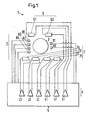
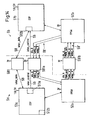
- Fig. 1 shows a schematic block diagram of the essential parts of a first Embodiment of the rotary drive according to the invention, the as a bearingless motor is configured and is provided with the reference number 1 in its entirety.
- the rotary drive 1 comprises a stator 2, a permanent magnetic rotor 3 and a control device 5 with an actuating device 4, which comprises a plurality of bipolar power amplifiers 41.
- the Control device 5 also includes the entire control and regulation units for the Operation of the rotary drive 1 are necessary. These are in Fig. 1 for the sake of better Overview not shown in detail. The structure of the control device 5 will be discussed later described in detail.
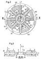
- stator 2 and the rotor 3 are shown in a top view in FIG. 2 and in one in FIG. 3 Section along the line III-III in Fig. 2nd
- Fig. 3 also illustrates the stipulation of a stator system to which in the description Reference is made.
- the stator system is a Cartesian coordinate system with the Axes X, Y and Z, the origin of which lies in the center of the stator and that with respect to Stator 2 is stationary.
- the Z axis points in the direction of the target axis of rotation of the rotor 3, which means that axis of rotation A about which the rotor 3 in the operating state rotates when it is in an exactly centered position (target position) with respect to the stator 2 located, in particular is not tilted.
- the direction of the Z axis is in hereinafter referred to as the "axial direction”.
- the direction of the X and Y axes of the Stator systems is arbitrary.
- the X-Y plane spanned by the X and Y axes is the Plane in which the rotor 3 rotates if it is not tilted or deflected in the axial direction is.
- the position of the rotor 3 (or its center) with respect to the X-Y plane is in Hereinafter referred to as its "radial position".
- the stator 2 comprises a drive winding 6 for Generating a magnetic drive field, which causes a torque on the rotor 3 and drives this, as well as a control winding 7 for generating a magnetic Control field with which the radial position of the rotor 3 can be regulated.
- the rotor 3 can be driven and magnetic stored in the stator 2 without contact, without the need for separate magnetic bearings are.
- there are three degrees of freedom of the rotor namely its rotation actively magnetically controlled around the axis of rotation A and its radial position (two degrees of freedom) or regulated.
- the drive winding 6 has two strands 61, 62, each belong to another drive phase, i.e. the drive winding 6 is two-phase (with two drive phases).
- the control winding 7 has four strands 71, 72, 73, 74 each belong to a different tax phase, i.e. the tax winding is four-phase (with four tax phases).
- the stator 2 comprises several, in the first exemplary embodiment eight, stator teeth 21-28 which by means of a yoke 20, usually an iron yoke, magnetically to one another are coupled.
- stator teeth 21-28 are the drive and control windings 6 and 7, respectively wound in the form of discrete coils.
- Several discrete coils can be electrically connected be connected in parallel or in a series connection. With the label "Strand” means the entirety of all of the discrete coils that are electrically parallel or are connected in series. Of course, a strand can only be a discrete coil include.
- phase refers to a strand and the part of it that supplies it Actuating device 4, in particular here the power amplifier 41, which carries this strand supplied with a phase current or with a phase voltage as a manipulated variable.
- the Actuator 4 can be used as a current regulator or as a voltage regulator for the drive and Control winding 6.7 may be formed. Since in most cases current controls are used find below, reference is made to the case where the manipulated variables Are phase currents. For voltage regulation with phase voltages apply as manipulated variable however, the same explanations.
- drive coils 611, 621 show the two-phase drive winding 6 in the first Embodiment of four concentrated coils, which are referred to below as drive coils 611, 621 can be designated.
- the two drive coils 611 form one strand 61 of the Drive winding 6, while the two drive coils 621 the other strand 62 of the Form drive winding 6.
- Drive coils that belong to the same drive phase are included Identical reference numerals.
- Each drive coil 611, 621 is a concentrated coil each wound around two immediately adjacent stator teeth 21-28 such that none of the Stator teeth 21-28 carries more than one drive coil 611, 621.
- the first Drive coil 611 is wound around the first and second stator teeth 21 and 22, respectively, the next Drive coil 621 around the third and fourth stator teeth 23 and 24, the next drive coil 611 around the fifth and sixth stator teeth 25 and 26 and the last drive coil 621 around the seventh and eighth stator teeth 27 and 28.
- the drive coils 611, 621 are like this interconnected that two diametrically opposite drive coils 611 or 621 form a strand 61 or 62 of the drive winding 6 and thus the same Drive phase belong.
- the distribution of the drive coils 611, 621 on the stator teeth 21-28 and their connection to the two strands 61, 62 of the drive winding is shown in FIG. 5 again illustrated in a more schematic representation, the upper part of FIG. 5 the strand 61 of the first drive phase and in the lower part of FIG. 5 the strand 62 of the second drive phase is illustrated.
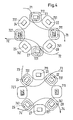
- control winding 7 which comprises eight concentrated coils, which are referred to below as control coils 711, 721, 731, 741. Every control coil 711,721,731,741 is wrapped around another stator tooth 21-28, that is to say each stator tooth carries exactly one control coil. Two control coils 711 or 721 or 731 or 741 each form a strand 71 or 72 or 73 or 74 of the control winding 7 and thus belong to the same tax phase. The control coils belonging to the same tax phase are included Identical reference numerals.
- the control coils are interconnected so that the control coil wound around a first stator tooth and the one around the Seen circumferential direction of the stator next to the stator tooth wound control coil belong to the same tax phase.
- This connection of the individual control coils 711, 721, 731, 741 is illustrated in a schematic representation in FIG. 4.
- the control coil 711, which is wound around the first stator tooth 21 (FIG. 4, top) and the control coil 711, which is wound around the third stator tooth 23, are interconnected and form the strand 71 the first control phase of the control winding 7.
- the two control coils 721 on the fifth or seventh stator tooth 25 or 27 form strand 72 of the second control phase.
- the two Control coils 731 on the second and fourth stator teeth 22 and 24 form the strand 73 the third control phase (Fig. 4, bottom), and the two control coils 741 on the sixth or eighth stator tooth 26 or 28 form the strand 74 of the fourth control phase.
- the drive winding has one Number of pole pairs one and the control winding a number of pole pairs two.
- General for the Rotary drive 1 according to the invention is preferred in those configurations in which the Differentiate the number of pole pairs of the drive winding and the control winding by one that is, if p denotes the number of pole pairs of the drive winding, then the control winding preferably the number of pole pairs p ⁇ 1, either p + 1 or p-1.
- the actuating device 4 (FIG. 1) is designed such that the phase current (or the phase voltage) as a manipulated variable for each phase 61.62 of the drive winding and for each strand 71-74 of the control winding regardless of the phase currents (or Phase voltages) is adjustable for the other strands.
- the control device includes in the first embodiment six separate bipolar power amplifiers 41, namely for each of the two drive phases and one for each of the four control phases. This is ensures that even if a complete drive and / or control phase fails remaining error-free phases can continue to be operated without restrictions.
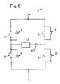
- the bipolar power amplifiers 41 are each H-bridge switching amplifiers.
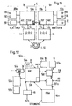
- Fig. 6 shows the electrical circuit diagram of such Power amplifier 41, one of the phases (here the strand 61 of the drive winding) supplied to the phase current.
- the power amplifier 41 is in a manner known per se with the Switching transistors T and freewheeling diodes F designed and is with the two Operating potentials + and - operated, the operating potential - for example that Earth potential is GND and the operating potential + is a potential of + 12V.
- the Switching transistors T are preferably field-effect transistors (FET) and in particular MOS-FETs.
- a current measuring device 411 is provided for measuring the respective phase current.
- the individual power amplifiers also as bridge branches of a multi-phase current controller be realized and several phases connected in a neutral connection, but then the star point must be at a resilient potential in order for the to ensure independent regulation of the individual phase currents.
- a resilient Star point switching is, for example, in European Patent Application No. 99810553.0 to the same applicant and is therefore not explained in detail here. But it can other forms of switching amplifiers or analog amplifiers can also be used.
- the power amplifier 41 is designed such that it can be operated bipolarly, which means that both the phase currents and the phase voltages are positive and can accept negative signs.
- the actuator 4 must each Drive and each control phase with one manipulated variable (phase current or Phase voltage) can supply, regardless of the manipulated variables for the others Phases is adjustable.
- the permanent magnetic rotor 3 of the rotary drive 1 has two poles (Number of pole pairs one) diametrically magnetized and designed as an annular rotor 3 with a permanent magnetic ring 31 and an iron yoke 32, the radially inner is arranged with respect to the ring 31.
- the magnetization of the rotor is symbolic in Fig. 2 represented by the arrow M. Of course, there are other pole pair numbers and other shapes rotor magnetization possible.
- the rotor 3 can in particular also be disk-shaped be trained.
- Embodiment four position sensors 81,82,83,84 (see Fig. 1) provided, of which two each, namely the position sensors 81, 82 and the position sensors 83, 84 to one
- Two-axis measuring system 80a, 80b (see Fig. 11) belong to which the radial position of the rotor 3 can be determined.
- the position measurement of the rotor 3 is designed redundantly, whereby the fault tolerance of the rotary drive 1 increases. This will be explained later.
- Each position sensor 81-84 preferably comprises two sensor elements 811, 812; respectively. 821,822 or 831,832 or 841,842 (see Fig. 2).
- Each sensor element is in a groove arranged between two adjacent stator teeth 21-28 opposite the rotor 3, so that there is exactly one sensor element in each of the eight grooves.
- the sensor elements can be arranged either in the X-Y plane or slightly axially offset to this.
- Two sensor elements 811, 812; or 821.822 or 831.832 or 841.842, which at same position sensor 81 or 82 or 83 or 84 belong, are with respect to
- the circumferential direction of the stator 2 is offset by 180 ° to one another, so that they are diametrically opposite in the stator 2 (see Fig. 2).
- systematic errors such as common mode disturbances, offsets, drifts, in particular thermal drifts in position sensors 81-84 can be eliminated by Difference signal from the two signals of the sensor elements, which are the same Position sensor 81-84 belong, is used for the determination of the rotor position.
- the two position sensors belonging to the same two-axis measuring system e.g. B. the two position sensors 81 and 82 with their four sensor elements 811,812,821,822 offset relative to each other by about 90 ° with respect to the circumferential direction of the stator arranged and relative to the position sensors 83, 84 of the other two-axis measuring system offset by about 45 °.
- sensor elements 811-842 suitable, in particular eddy current sensors, inductive sensors, magnetic field probes such as Hall sensors, optical sensors, capacitive sensors.
- the sensor elements are preferred Eddy current sensors.
- the bearingless motor drive and position of the rotor 3
- the usually by means of a vector control or a field-oriented control method takes place, it is necessary to change the direction of the rotor magnetization, i.e. the current one Position of the magnetization of the rotor 3 relative to the X-Y plane of the stationary stator system know.
- This size is usually referred to as the rotor field angle.
- At least one field sensor is provided to determine the rotor angle.
- any field sensor 91.92 comprises two magnetoresistive field measuring bridges, the magnetoresistive Elements are, for example, Giant Magneto-Resistive (GMR) elements.
- GMR Giant Magneto-Resistive
- the field sensors 91 and 92 are axially offset to the X-Y plane, namely arranged below the rotor 3 as shown.
- the rotary drive 1 can have a reduced Number of drive phases and / or control phases continue to be operated properly, because the phase current for each individual drive phase and for each individual control phase can be regulated completely independently of the other phase currents. Since it is the Minimum requirement for a reliable drive and for a reliable magnetic Storage of the rotor is that at least one drive phase and at least two Control phases can work error-free in the first embodiment in extreme cases one drive phase and two control phases fail completely or are deactivated without that the rotary drive 1 loses its functionality. On the handling of the errors discussed in more detail later.
- the rotary drive 1 works according to the principle of the single-phase AC motor. As long as the rotary drive 1 is not in this case stopped, it continues to rotate, so it is still working correctly. If such a single phase AC motor is stopped, however, it is depending on the relative position of the rotor 3 Stator 2 possible that the rotary drive 1 can no longer be started easily. It is then possible, however, by activating the still error-free process Control phases to roll the rotor 3 along the stator 2 until the rotor 3 in is in a position in which it can be started with a drive phase. Once the Rotor 3 rotates again, then operation with only one drive phase and at least two Tax phases are maintained.
- FIG. 7 shows a top view of the stator 2 of a variant of the first exemplary embodiment.
- the control winding comprises a total of sixteen control phases and two drive phases concentrated control coils 711,721,731,741, with two on each stator tooth 21-28 Control coils are provided.
- Four control coils each, four different Stator teeth are wound to form a 71-74 strand of the control winding interconnected and thus belong to the same tax phase (which have control coils again identical reference numerals).
- the interconnection of the individual control coils is the schematic representation in Fig. 8 can be seen.
- the first strand 71 see Fig.
- control winding is made by interconnecting one of the two control coils realized that arranged on the first, third, fifth and seventh stator tooth 21,23,25,27 are. These control coils are designated by the reference number 711.
- the second strand 72 the control winding is connected by interconnecting the other control coils on the first, third, fifth and seventh stator tooth 21, 23, 25, 27, that is not to the first phase 71 belong, realized. These control coils are designated by the reference number 721.
- the Control coils 721 of the second phase 72 are therefore on the same stator teeth as the control coils 711 of the first strand 71.
- the first and the second strand are thus in essentially by identical arrangement and interconnection of their respective Control coils realized.
- control coils of the third and fourth phases 73 and 74 which with the Reference numerals 731 and 741 are designated. (Fig. 8, below). These are each on the second, fourth, sixth and eighth stator tooth 22, 24, 26, 28 arranged.
- control coils are thus to the individual strands of the control winding interconnected that seen in the circumferential direction of the stator 2 each around immediately adjacent stator teeth wound control coils to different strands belong to the tax winding.
- the two control coils which are arranged on the same stator tooth, can be arranged side by side, as shown in Fig. 7.
- each two control coils which are wound around the same stator tooth, wound on one another, so that the outer control coil surrounds the inner control coil.
- FIG. 8 shown schematically.
- the four control coils that make up the same strand of control winding are interconnected, only the outer or only the inner control coils. So are z. B. the control coils 711 of the first strand 71 only outer coils, while the Control coils 721 of the second strand are only inner coils.
- the individual control coils are preferably designed so that the ohmic resistance of the strand, that of external Control coils is formed, for. B. strand 71, either the same size (symmetrical Configuration) or larger (asymmetrical configuration) than the ohmic resistance the strand formed by the inner control coils, e.g. B. Strand 72.
- the two-phase drive winding is configured in the same way as in FIG. 5 is shown and already explained in connection with the first embodiment has been.
- the configuration of the control winding shown in FIGS. 7 and 8 has the following advantage: In normal operation, the position of the rotor with all four control phases, i.e. with all sixteen control coils, regulated. Since two control coils are arranged on each stator tooth are only half the current that would be required to flow through them generate the same field with only one control coil on this stator tooth. Twice the half In terms of losses, however, electricity is cheaper than all the electricity. Now falls one Control phase, for example the first strand 71, this can be done in a simple manner be compensated for that the phase current in phase 72 of the second control phase doubles becomes. This is done automatically by the regulation.
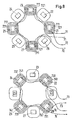
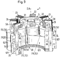
- Fig. 9 shows a perspective view and partially in section a second Embodiment of the rotary drive 1 according to the invention, the so-called Temple engine is designed.
- a temple engine is, for example, in the one already cited WO-A-98/11650 discloses (see there Fig. 8k and associated text passages).
- the stator 2 of the Tempelmotors has several, here eight, stator teeth connected by a yoke 20 21-28 (only six stator teeth 21-25, 28 can be seen in FIG. 9).
- the conclusion 20, which magnetically couples the stator teeth 21-28 is made of a ferromagnetic Marterial, preferably iron.
- Each stator tooth 21-28 is L-shaped a longer leg SL and a shorter leg SK.
- the longer leg SL extends in the axial direction and the shorter leg SK runs radially inside, so towards the rotor.
- the drive and control coils are 611,621,711,721,731,741 wrapped around the longer legs SL of the stator teeth 21-28.
- the embodiments of the 2 and 7 ("planar" design) on the one hand and FIG. 8 (Temple motor) on the other hand can be controlled in an identical manner, functionally equivalent, especially of their electrical mode of operation, and in particular have the same Effect on the permanent magnetic rotor 3.
- the L-shaped stator teeth are 21-28 from the functional principle equivalent to the "straight" stator teeth 21-28 as shown in Fig. 2 and Fig. 7 are shown.
- the winding, arrangement and connection of the drive coils 611 and 621 is the same as it is shown in FIG. 5 and has already been explained.
- the strands 71-74 of the tax phases can either use eight discrete control coils 711,721,731,741, i.e. one per stator tooth, be configured, which are arranged and connected as shown in FIG. 4, or with sixteen discrete control coils 711, 721, 731, 741, i.e. two per stator tooth, which according to FIG are arranged and connected.
- two control coils per stator tooth can these two control coils adjacent with respect to the axial direction, or what it is preferred to be wound on one another, as has already been explained above.
- the 9 with four control phases and two drive phases is functional equivalent to the first embodiment or its variant.
- the related Explanations apply analogously to the design as Temple engine according to FIG. 9.
- the temple motor can also have a different number of stator teeth and / or be designed with a differently designed drive winding and / or control winding.
- the Position sensors and the field sensors are not shown in FIG. 9. If the Rotary drive according to the invention is part of a blood pump, it is preferably as Temple engine designed, as will be explained later.
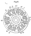
- FIG. 10 illustrates a third in a representation corresponding to FIG. 2 Embodiment of the invention, in which the rotary drive 1 exactly three drive phases and has exactly three tax phases.
- the rotary drive 1 exactly three drive phases and has exactly three tax phases.
- the following is only the differences to the first two exemplary embodiments discussed in more detail. Otherwise the above apply Explanations in a similar manner also for the third embodiment.
- identical or functionally equivalent parts are the same Reference numerals.
- the stator 2 has twelve stator teeth 21-29,210,211,212, between which the rotor 3 can be magnetically supported.
- the drive winding has three strands, each of which is interconnected by two discrete drive coils 611,621,631 is realized. So there are a total of six drive coils 611,621,631 are provided, which are each formed as concentrated coils.
- Each Drive coil 611, 621, 631 is analogously the same as in connection with FIG. 2 explained wrapped around two immediately adjacent stator teeth.
- the two of them diametrically opposite drive coils 611 or 621 or 631 are one
- the drive winding is connected, that is, the two with the reference number 611 provided drive coils form the first strand of the drive winding, the two with the Drive coils designated by reference numeral 621 form the second strand of the Drive winding and the two drive coils designated by reference number 631 form the third strand of the drive winding.
- the three-phase control winding comprises twelve discrete control coils 711, 721, 731, which act as concentrated coils are formed, and of which four control coils form a strand form the tax winding, i.e. belong to the same tax phase.
- a control coil is provided in each case.
- the four with the reference number 711 designated control coils around the first, fourth, seventh and tenth stator tooth 21,24,27,210 are connected to the strand of the first control phase, the four with 721 designated control coils on the second, fifth, eighth and eleventh stator tooth 22,25,28,211 form the strand of the second tax phase, and the four designated 731 Form control coils on the third, sixth, ninth and twelfth stator teeth 23,26,29,212 the strand of the third tax phase.
- the position sensors are preferably between two each Adjacent stator teeth are arranged in the same way as already explained above has been.
- the field sensors are preferably analogous to those in FIG. 2 and FIG. 3 shown, axially offset from the X-Y planes below or above the rotor 3 arranged.
- the adjusting device 4 designed to supply the individual strands of the drive and control windings is that each drive phase and each control phase are completely independent of the others Phases can be controlled or operated. It is also preferred for each of the three Strands of the drive winding and one for each of the three strands of the control winding separate bipolar power amplifier 41 (Fig. 1, Fig. 6) is provided so that the Phase current (or phase voltage) for each strand of the drive winding and for each Strand of the control winding regardless of the phase currents (or Phase voltages) is adjustable for the other strands. Regarding further details of the fault-tolerant design with three drive phases or with three control phases is on the two already cited European patent applications No. 99810553.0 and No. 99810760.1 referred.
- the third exemplary embodiment as a temple motor can be designed.
- Control coils and / or the drive coils in the form of distributed windings.
- any control device with which a control device 5 is suitable (FIG. 1) bearingless motor can be operated, provided the control device 5 is modified so that a completely independent control and bipolar operation of each one Drive phase and each individual control phase enables.
- Control device 5 which is characterized by its additional high fault tolerance distinguished. Reference is made to the case where the drive winding 6 is accurate is two-phase and the control winding 7 is exactly four-phase. However, this is not mandatory requirement.
- This control device 5 can be used in an analogous manner can also be designed for a different number of drive phases and / or control phases.
- the Control device comprises two almost identical control systems 5a, 5b, each of which alone and independently of the other control system, the bearingless motor 1 (here symbolically represented as a blood pump 10) can operate.
- both control systems 5a, 5b are active and together regulate the operation of the bearingless motor 1.
- either of the two control systems directly control and regulate the operation of the bearingless motor 1 alone, that is to say proper operation of the engine 1 is both in terms of drive and in terms of storage with only one of the two control systems 5a, 5b possible.
- This is hot Redundancy means a significant increase in operational safety, which is particularly important for Blood pumps is a big advantage.
- the Bearingless engine can continue to work even if both control systems 5a, 5b fail Major disturbances occur, for example physical contact between the rotor and stator.
- This has the advantage that if both control systems 5a, 5b fail enough time remains to reset at least one of the two control systems 5a, 5b to restart; for such a reset is typically only a time of about a millisecond. Is the reset for at least one control system successful, the normal operation can be continued.
- Each control system 5a, 5b comprises at least the following components: at least two position sensors 81.82 and 83.84, each a two-axis measuring system 80a, 80b for determining the radial position of the Form rotor 3; Means for determining the rotor angle, here at least one Include field sensor 91.92 per control system; at least three separate ones, in one Power section 4a, 4b provided power amplifier 41 for supplying the individual strands the drive and control winding; and a signal processing and control device 50a, 50b, which processes the sensor signals, the regulation of the drive and the position of the Performs rotor, and controls the power section 4a, 4b with the power amplifiers 41.
- the Power amplifiers 41 of each control system 5a, 5b control at least one drive phase and at least two control phases so that each control system alone drives the motor 1 can operate.
- the power section 4a supplies, for example, the line 61 (see FIG. 5) Drive winding 6 and the two strands 71, 73 (see FIGS. 4 and 8) of Control winding 7, while the power section 4b, the phase 62 of the drive winding 6 and feeds the two strands 72, 74 of the control winding 7.
- every control system controls in each case one of the strands 71, 72 of the control winding, which are shown in the upper image in FIG. 8 and one of the strands 73, 74 of the control winding, which are shown in the lower image in FIG. 4 and Fig. 8 are shown.
- Each control system 5a, 5b comes with two voltages, here a regulated DC voltage of 3V (3V_A or 3V_B) and a DC voltage of 12V (12V_A or, 12V_B) supplied
- the signal processing and control device 50a, 50b is usually on a chip or is implemented in an electronic print, it is referred to below as a DSP board (DSP: Digital Signal Processor).
- DSP Digital Signal Processor
- the other components of the control systems 5a, 5b are preferably implemented in the form of electronic prints or chips, such as the Representations indicate in particular in FIGS. 11, 15-18.
- Control device 5 can respond optimally to different fault conditions each control system 5a, 5b on the process and system data necessary for operation are (software, etc.).
- the two control systems 5a, 5b can send signals to one another exchange and can mutually over a parallel or serial data connection (parallel or serial data bus) monitor and check.
- the two control systems 5a, 5b Exchange synchronization signals with each other in order to switch the switching cycles Power amplifier 41 (H-bridges) and the excitation frequencies of the position sensors synchronize with each other so that no interference occurs here.
- the connections for the exchange of the synchronization signals can be opened immediately in the event of an error.
- control systems 5a, 5b The essential components of the control systems 5a, 5b are described in detail below described.
- the DSP board 50a is responsible for regulating the position of the rotor 3 and the phase currents for the drive and control phases, reading and interpreting all the information and sending out control signals to the various components.
- the "brain" of the DSP board 50a comprises a processor unit, namely the digital signal processor (DSP) 51a.
- DSP digital signal processor
- the following components are also provided on the DSP board: a logic provided with the reference symbol 52a, which is referred to as FPGA (Field Programmable Gate Array), a flash memory 53a, two analog-digital converters 54a (ADC), a clock generator 55a, a linear regulator 56a, and a watchdog 57a.
- FPGA Field Programmable Gate Array
- interprocessor connections 58, 59 are provided as communication means, each of which comprises a driver or transceiver 581, 591a.
- the supply voltages are symbolically represented by the small arrows labeled 3V or 1.8V / 3V.
- the entire system is operated in a manner known per se via a so-called transcutaneous Transcutaneous Energy Transfer System (TETS) with energy provided. Data can also be transmitted via the TETS, e.g. B. Downloads or Program changes.
- TETS is via a communication interface KS with the DSP connected.
- the DSP 51a, 51b is, for example, a processor of the TMS320VC5402 type from Texas Instruments, e.g. B. is clocked at 100 MHz or 50 MHz.
- the DSP needs two Supply voltages, namely 3 V and 1.8 V, are still discussed on their provision becomes.
- the 3V voltage is required for the output pins, while the 1.8V is used for the supply serve the core unit.
- the above-mentioned DSP 51a, 51b has a 16K ⁇ 16 bit RAM memory with double access, which allows the entire control program for the bearingless motor in the DSP 51a, 51b to perform itself without the external flash memory 53a, 53b to access.
- the FPGA 52a, 52b contains the connection logic (glue logic) and is used for generation the pulse width modulation (PWM) with which the power amplifiers 41 are controlled.
- the FPGA 52a, 52b is, for example, from the Actel 42MX family, because it is very are small (requires little space) and also use little energy.
- the FPGA 52a, 52b on the one hand comprises the connection logic which the DSP 51a, 51b for decoding Addresses and for monitoring, and secondly a PWM generator 521a (see Fig. 13), which the PWM signals for driving the switching transistors T (see Fig. 6) of the Power amplifier 41 generated.
- FIG. 13 shows a block diagram of the FPGA 52a, in which the individual modules of the FPGA 52a of the master 5a are shown.
- the module addresss_decod communicates with the Address bus of the DSP 51a (arrow "addr_bus") and decodes the addresses by the DSP 51a be transmitted.
- the FPGA_test module is a counter that is driven by the clock generator 55a same control system 5a is clocked (signal 5MHz_A). The DSP 51a can use this counter read out. If its value no longer changes, the DSP 51a decides that the FPGA 52a has failed and switches to the corresponding error mode (see further below).
- the FPGA_watchdog module is a monitoring unit (internal watchdog) for the FPGA 52a.
- This module is a resettable counter provided by the other's clock 55b
- Control system 5b is clocked (signal 5MHz_B) and during each software cycle a signal DSP_alive is reset.
- the signal DSP_alive is from the DSP 51a of the same control system 5a generated. If this signal fails to appear because, for example, the DSP 51a has failed or the software cycle is not running correctly, so generated the module FPGA_watchdog a signal power_reset, which on the one hand via a module power_enable (see below) temporarily the 12V supply of the power amplifier 41 switches off (dis_12V) and on the other hand gives a reset to the DSP 51a. After successful Reset the 12V supply is switched on again. The entire reset process can be done in less than a millisecond, so in the event of a successful Resets no influence on the proper bearing and drive function occurs.
- the module syst_stat_in is a control word that can only be changed by the DSP 51a. By changing specific bits of this word, the DSP 51a can switch off the 3 V supply voltage of the control system 5b cause (dis_B). Furthermore, the module syst_stat_in own phases, that is, the individual power amplifiers 41 of those Drive and control phases, which are controlled by the control system 5a, via the module Deactivate power_enable, which is connected to the module syst_stat_in, individually (dis_ch1,2,3) or activate. The power_enable module can also handle the entire 12V supply voltage the power amplifier 41, which is controlled by the control system 5a be deactivated (dis_12V).
- the module syst_stat_out contains various information, e.g. B. whether and if so, in which power amplifier 41 (H-bridge) an overcurrent flows (oc_ch1,2,3) whether there is an overcurrent in the 12V supply voltage of the power amplifier 41, e.g. B. due to a short circuit, flows (oc_ch12V) whether a malfunction in the excitation of the sensors of the control system 5a is present (sens_err_A) or whether the watchdog 57b of the other control system 5b reports an error (wdog_B), which indicates that the DSP 51b of the other control system 51 b no longer works or does not work correctly.
- the module FPGA_monoflop is a circuit that the clock 55b of the other control system 5b monitors (5MHz_B) and generates a signal (clkB_alive) that indicates whether this clock 55b still working.
- the module sens_sync synchronizes the excitation frequencies (5MHz_A, 5MHz_B) for the position sensors of the two control systems 5a, 5b and has as Output signal the synchronized excitation frequency (5MHz_sens). This is in the module clk_div_2 divided by sixteen and as the excitation frequency (312 kHz) for the Position sensors provided.
- the master 5a sets the clock for the measuring systems (position and field sensors) of both control systems 5a, 5b.
- the module clk_div_1 divides the clock signal at its input (50MHz_A), which is identical to the clock signal for the DSP 51a (50 MHz or 100 MHz clock frequency), by ten and by five and thus provides the 5 MHz and a 10 MHz clock signal at its output ready for the control system 5a (10MHz_A, 5MHz_A).
- the module is cs_generator a chip select generator that addresses the circuits of each control system so that the DSP 51a can communicate with them via a bus.
- the PWM generator 521a (module PWM_gen) is clocked at the 10 MHz clock frequency (10MHz_A) and controls the individual switching transistors T (see FIG. 6) of the H-bridges Power amplifier 41, so that the correct phase voltage at the associated Apply the strand of the drive or control winding.
- the PWM generator 521a also receives an Synchronization signal (PWM_sync) that ensures that the two PWM generators 521a, 521b of master 5a and slave 5b synchronously and not working against each other.
- PWM_sync Synchronization signal
- the DSP 51a which is the control setpoints for the phase voltages of the two Control phases and the drive phase calculated, transmits this data via a data bus (data_bus) to the PWM generator 521a.
- the FPGA 52a also receives this data bus other data it needs.
- the flash memory 53a, 53b is a CMOS permanent memory (non-volatile memory), which with the supply voltage of 3V works. In it is the entire program for the operation of the bearingless motor saved.
- the capacity of this flash memory 53a, 53b is z. B. 256Kx16 bit.
- the flash memory 53a, 53b is only required if the entire system (Rotary drive 1 including control device 5) is restarted when the DSP 51a, 51b is completely reset (Reset), or if the Program should be saved. In the event of a restart or a reset of the DSP 51a, 51b is the entire program for the operation of the bearingless motor from the flash memory 53a loaded into the internal RAM memory of the DSP 51a, 51b via a bus.
- the program is updated during operation, it is saved in the flash memory 53a, 53b, while the DSP 51a, 51b is still with the older one, in his internal RAM stored program version operates the rotary drive 1.
- the new one Program (update) completely loaded into flash memory 53a, 53b, checked and validated the DSP 51a, 51b receives a reset command and then takes over the new program from the flash memory 53a, 53b into its internal RAM memory to make it available for further use Operation.
- the flash memory is in normal operation 53a, 53b in a sleep mode in which it consumes almost no energy.
- the two ADCs 54a, 54b that each of the two control systems 5a, 5b has are, for example each four-channel analog-digital converter.
- Each control system 5a, 5b can thus have eight Read analog signals, whereby two can be read simultaneously.
- Eight Analog inputs become three for the three phase currents from the three ammeters 411 used in the H-bridges of the three power amplifiers 41 (see FIG. 6), two for the two position signals from the two position sensors 81.82 and 83.84 and two for the two signals (sine and cosine) from field sensors 91 and 92, respectively.
- the remaining one Entrance can be used for other purposes.
- the ADCs 54a, 54b communicate with the DSP 51a, 51b via two serial connections that are independent of the parallel data bus via which the two DSPs 51a, 51b with each other and with the flash memory 53a, 53b communicate, and thus also independently of the FPGA 52a, 52b.
- the clock generator 55a, 55b uses a crystal to generate a clock frequency for the Control system 5a, 5b.
- the clock generator 55a, 55b is, for example, a parallel resonance crystal.
- the linear regulator 56a generates the direct voltage of from the supply voltage of 3V 1.8 V for the DSP 51a, 51b.
- direct current converters DC-DC converter
- they use a little less energy, they require a lot more Space on the electronics board as the linear controller 56a. The latter is therefore preferred.
- the DSP 51a, 51b is monitored and specifically the presence of the two Voltages of 3V and 1.8 V.
- the watchdog 57a, 57b must be regularly from the DSP 51a, 51b are controlled (triggered). If this signal is missing, then after one predeterminable time of 1.6 seconds, for example, a reset pulse is generated.
- a reset pulse is generated.
- the Watchdogs 57a, 57b can view the two DSPs 51a, 51b in normal operating state monitor each other. If a DSP, for example the DSP 51a during a the other time can not access the watchdog and trigger a reset DSP 51 b detect this state and react to it. If the error after the reset has not disappeared and in turn results in a reset, the The supply voltage of the DSP 51a is switched off by the DSP 51b, causing this is deactivated.
- the interprocessor connections 58, 59 via which the two control systems 5a, 5b communicate with each other and through which they monitor and control each other, comprise a data connection 58 (inter_data) and a control connection 59 (inter_control). So that the two control systems are optimal in normal normal operation can work together, and so that they can react to errors, needed each DSP 51a or 51b some information from the other DSP 51b or 51a, for example values for the position of the rotor, values for the rotor angle, information about the status of the other control system, clock and synchronization signals that Signals of the watchdog 57a or 57b, as well as the possibility of the other Disable control system.
- inter_data values for the rotor position, for the rotor angle, etc.
- inter_control the control signals for communication via the interprocessor connection 59
- inter_control the control signals for communication via the interprocessor connection 59
- These interprocessor connections 58, 59 are mainly through Connections (inter_control, inter_data) between the data / address bus 511a of the DSP 51a of the master 5a and an HPI (host port interface) 512b of the DSP 51b of the slave 5b.
- the master 5a can use all of these connections 58 and 59 to provide all the information required read the program and data RAM of the DSP 51b of the slave 5b.
- one Connection 59 'between the FPGAs 52a, 52b of the two control systems 5a, 5b is provided, Via which the two FPGAs 52a, 52b control signals (dis_A, B; PWM_sync; 5MHZ_A, B; Exchange wdog_A, B).
- the two FPGAs 52a, 52b control signals (dis_A, B; PWM_sync; 5MHZ_A, B; Exchange wdog_A, B).
- FIG. 15 schematically shows the structure of the power section 4a, 4b, which, as indicated in FIG. 15, comprises three subsystems, namely one for each power amplifier 41. In FIG. 15, only one of these subsystems is shown in detail.
- the subsystem of the power section 4a comprises the power amplifier 41, which is designed as an H-bridge switching amplifier (see also FIG. 6) and here, for example, drives the line 61 (symbolically indicated) of the drive winding.
- the switching transistors T are, for example, n-channel field effect transistors (FET) with a low drain-source resistance R DSon . Two FETs are arranged in a common, very small housing. Due to the low value of R DSon , no additional cooling is necessary.
- the subsystem also includes a driver 42a for driving the switching transistors T.
- Der Driver 42a is driven with the PWM signals FPGA_PWM by the associated one FPGA 52a are generated and have a voltage level of 3V.
- the driver 42a transforms these signals into 12V signals and controls the upper and lower ones Switching transistors T (as shown).
- Driver 42a further includes one Protection circuit that prevents a lower and an upper FET at the same time are closed.
- the driver 42a can receive a signal FPGA_DIS from the FPGA 52a a circuit 417 can be deactivated. In the event of a fault, the FETs can be within about 100 Open nanoseconds.
- the current measuring device 411 for determining the phase current comprises a shunt resistor 412 of, for example, 10-50 milliohms, and an operational amplifier 413, which Output signal of the shunt resistor 412 amplified and as a signal Current_Meas to the DSP board 50a transmitted.
- the shunt resistor 412 is in the H-bridge between the Source of an FET and the negative operating potential, here the earth potential of the 12V DC voltage, arranged and delivers a signal whose size is linear from that Phase current depends.
- Each subsystem of the power section 4a also includes an overcurrent fuse 414 a further shunt resistor 415 and a further operational amplifier 416.
- the Output of this operational amplifier 416 is connected to the circuit 417, which the Driver 42a can turn off.
- the shunt resistor 415 of the overcurrent fuse 414 is between the H-bridge of the power amplifier 41 and the negative operating potential, here the earth potential of the 12V DC voltage. The one via the shunt resistor 415 falling voltage is amplified in the operational amplifier and with a predeterminable Limit value compared, from which a digital output signal overcurrent is generated.
- the FPGA_OC signal is sent to the associated FPGA 52a sent, which turns off the driver 42a.
- the overcurrent protection 414 is designed to be fast enough to complete a full DC short circuit between the two operating potentials of the 12V DC voltage via the H-bridge prevent.
- Each control system 5a, 5b has its own, separate and complete two-axis measuring system 80a, 80b with position sensors 81.82 and 83.84 for determining the radial position of the rotor 3.
- FIG. 16 shows the block diagram of such a two-axis measuring system 80a with the two position sensors 81 and 82, which are preferably each comprise two sensor elements 811,812 and 821,822 in a 180 ° arrangement (see above, especially Fig. 2 and Fig. 7).
- the two-axis measuring system 80a, 80b there are two current position coordinates of the rotor with respect to the X-Y plane of the stator system can be determined, which are simply referred to below as the x and y components.
- Any two-axis measuring system 80a, 80b also includes the excitation circuit 85a, 85b, a monoflop 86a, 86b, two mixers 87a, 87b, namely one for each axis, and two amplifiers 88a, 88b.
- the excitation circuit 85a is fed with the 312 kHz frequency which is generated by the FPGA 52a is generated (see Fig. 13). This signal is amplified in the excitation circuit 85a and the individual sensor elements 811,812,821,822 supplied, which here as eddy current sensors are designed.
- the output signal of the excitation circuit 85a is from the monoflop 86a monitors which generates an error signal sens_err and transmits it to the FPGA 52a, as soon as the excitation frequency is no longer available. This is used for evaluation Output signal of the sensor elements 811, 812 for the x-axis of a first mixer 87a fed and the output signal of the two sensor elements 821,822 for the y-axis one second mixer 87a.
- Mixers 87a convert the output signals of the sensor elements, which are AC signals, into DC signals which depend on the current radial position of the rotor 3.
- This Direct current signals are in the amplifiers 88a connected downstream of the mixers 87a amplified and then transmitted to the ADC 54a (Fig. 12).
- an all-pass filter 89a can also be interposed in order to determine the phase shift to match between the excitation signal and the output signal of the sensor elements.
- Each field sensor 91, 92 comprises two magnetoresistive bridges 93 a, for example of type IMO LK15, the two signals phase-shifted by 90 °, for example generate a sine and a cosine signal, which of the angle and the Depend on the amplitude of the magnetic field.
- Each bridge 93a is an operational amplifier 94a connected downstream, which amplifies the output signal of the respective bridge 93a and on the ADC 54a (see FIG. 13).
- Fig. 18 shows a block circuit diagram of a supply circuit 500, which the Control device 5 supplied with energy.
- the control device 5 requires two different DC voltages, namely 3 volts in the exemplary embodiment described here and 12 volts, 12 volts being the positive operating potential for the power amplifiers 41.
- the negative operating potential is for both the 3V supply and the 12V supply each the earth potential GND.
- the supply circuit 500 is with a 3V and a 12V supply fed, which then fork each to each of the two control systems 5a and 5b to supply.
- the 12V supply can be in each of the two control systems 5a, 5b 12V_A or 12V_B for this control system by means of a switching transistor 501a, 501b, for example of type Si6954 from Vishay, can be switched on or off.
- the switching transistor 501a, 501b is controlled by a driver 502a, 502b, or switched. As soon as it receives the dis_12V_A or dis_12V_B signal, it interrupts via the Switching transistor 501a or 501b the 12V supply of the corresponding control system 5a or 5b.
- the signal dis_A or dis_B for switching off the respective 3V supply can only be supplied by the FPGA 52a, 52b (see FIG. 13) of the respective other control system, that is, only the FPGA 52a of the control system 5a can interrupt the 3V supply of the control system 5b, ie generate the signal dis_B and only the FPGA 52b of the control system 5b can supply the 3V supply to the control system 5a interrupt, i.e. generate the signal dis_A.
- the on / off pin for the 12V supply is via a pull-up resistor 503a, 503b connected to the 3V supply of the same control system. This ensures that when the 3V supply for this control system is switched off, the 12V supply automatically for this control system follows and is also switched off. On the other hand, the However, the 12V supply must be switched off independently of the 3V supply, that is when the 12V supply is deactivated in one of the two control systems 5a, 5b, the remains 3V supply of this control system received.
- the on / off pin for the 12V supply is also connected via the associated FPGA 52a, 52b Overcurrent fuse 414 (see Fig. 15) connected.
- step 19 shows a flowchart of a cycle of the basic structure of the software means the program according to which the control device 5 operates.
- the two Control systems 5a, 5b work in parallel, the basic scheme of the software for both Control systems 5a, 5b is identical.
- the double arrows in Fig. 19 symbolically show the Data exchange between the two control systems 5a and 5b.
- step 201 start the cycles for the two control systems 5a and 5b by an interrupt signal initialized, which is produced by the PWM generators 521a, 521b (FIG. 13).
- the Start time lies in an interval in which the power amplifier 41 is not switched.
- step 202 Measurement of Position and Field
- Step 203 is a running in the background Task in which each control system 5a, 5b checks or monitors the other, for example, by querying whether the other control system is in a given Period answers. If this is not the case and the other system is not reset can be woken up, it is completely switched off (see also Fig. 20 and the related explanations).
- step 204 the Values for the position of the rotor and / or the values for the rotor angle
- each Control system 5a, 5b has determined independently of the other control system between exchanged the two control systems 5a, 5b.
- the master 5a checks the values of the Slave 5b and decides if there are any deviations with the help of Error routines which of the values are correct. If necessary, error-corrected values certainly. After the correct or error-corrected values have been determined, these will be adopted by both control systems, so that both control systems with identical Work values for the position of the rotor and the rotor angle.
- step 205 Calculation of Forces, Torque
- each control system 5a, 5b carries out the control routines for the position and the Speed of the rotor and determines the required forces and control technology Torques to keep the rotor 3 centered in the stator 2 and around the rotation of the rotor 3 at the desired speed.
- step 206 the power amplifiers controlled in such a way that they feed the previously determined phase currents into the phase of the respective Memorize the drive or control phase.
- the two control systems work in the normal, i.e. error-free, operating state 5a, 5b in parallel (hot redundancy).
- Each control system 5a, 5b has its own position and field measurement, calculates the required forces and the required torque, and accordingly supplies the control phases and the drive phase with the respective Phase current.
- the control systems 5a, 5b exchange each of them determined values for the position of the rotor and for the rotor angle with each other to coordinate with each other. This ensures that the two control systems 5a, 5b do not work against each other.
- Failure mode 1 (A) occurs when in the two-axis measurement system 80a with the Position sensors 81, 82 there is an error. Then this measuring system becomes complete switched off and only the position values determined by the control system 5b are used for both Control systems 5a, 5b used.
- Error modes 1 (Ax) and (1Ay) occur if there is only one axis, namely the x or the y axis of the two-axis measuring system 80a is defective. Accordingly, too only one axis x or y switched off and the position value that with the still error-free Axis is determined, continues to be used to determine the position of the rotor.
- Fault mode 2 occurs when the field sensor 91 of the control system 5a is faulty works and is switched off. In this mode the rotor angle is only measured still with the field sensor 92 of the control system 5b.
- the failure mode 3 (A) means that the 12V supply of the control system 5a is complete is switched off. All three power amplifiers 41 of the control system 5a are in this mode deactivated, the bearingless motor is only with the drive phase and the two Control phases operated, which are controlled by the control system 5b.
- the DSP 51a and the position sensors 81, 82 and the field sensor 91 of the control system 5a operate in this failure mode 3 (A) yet.
- the faulty electrical phase is switched off.
- a fault can be, for example, a line break or a short circuit in one of the Be drive or control coils.
- the six error modes 3 (A1), 3 (A2), 3 (A3), 3 (A1,2), 3 (A1,3), 3 (A1,3), provided with the number or numbers in parentheses specify which of the phases is switched off in the respective error mode.
- the number 1 indicates the drive phase and the numbers 2 and 3 the control phases. So means For example, the failure mode 3 (A1,3) that the drive phase (1) and one of the two Control phases (3) is switched off and the other control phase (2) is still operated.
- error mode 4 (A) the entire control system 5a is switched off.
- the bearingless motor 1 is only with the control system 5b and the three of this control system 5b controlled phases operated.
- FIGS. 20a, 20b and 20c in their entirety show a flow diagram that shows one possible one
- the flow of an error detection routine is illustrated as it is in step 203 of the software cycle (see Fig. 19) is performed.
- the order of each check is but only to be understood as an example. Again, reference is made to the control system 5a taken.
- the routine for the control system 5b basically looks the same.
- Step 102 of the watchdog 57b of the control system 5b is queried. If this is at zero, the Step 103 switched off the 3V supply of the control system 5b and in step 103 'the Failure mode 4 (B) selected. Is the watchdog 57b not at zero or is it Interprocessor connection in order, so in steps 104 to 106 overcurrent checked. If an overcurrent flows in the 3V supply (step 104; overcurrent 3V?) in step 104 'the 3V supply is switched off and in step 104 "fault mode 4 (A) chosen.
- Step 105 If an overcurrent flows in the 12V supply (step 105; oc 12V?), In Step 105 'turns off all three power amplifiers 41, and in step 105 "the Failure mode 3 (A) selected. If an overcurrent (oc) occurs in one of the three phases ch_x, ch_y, ch_d flows (step 106), in step 106 'the corresponding power amplifier 41 (H-bridge) switched off and the associated error mode selected in step 106 ". In step 107 the individual phase currents checked for plausibility (check current of ch_d, ch_x and ch_y). If this test is negative for one of the three phases, step 106 '(see above) continued. In step 108 (FIG.
- step 20b it is checked whether an error signal sens_err from the two-axis measuring system 80a, 80b is present. If yes, the error mode 1 (A) is entered in step 108 ' changed, if no, it is checked in step 109 whether the values from the position sensors exceed a predeterminable range (pos_sens_check; limits exceed range?). If so, the error mode 1 (Ax) or 1 (Ay) is changed in step 109 '. In step 110 the Field sensor 91 checked (field_sens_check).
- step 110 "" is checked for both components of the signal of the field sensor whether you Mean is different from zero (field x or y average not 0?). If so, in Step 111 performed a calibration (online alignment) of the field sensor 91.
- step 112 the FPGA 52a is checked (FPGA_test). If errors are detected, the Step 112 'changed to failure mode 3 (A). In step 113 (Fig. 20c) the flash memory 53a tested (flash_test).
- step 114 If this does not respond or cannot be woken up, then it is registered in step 114 that the control system 5a cannot be restarted, but the normal operating state can be maintained.
- step 115 the ADCs 54a checked (ADC_test). If errors are detected in this test, step 116 checks which of the two ADCs 54a is defective and accordingly in the step 116 'or 116 "in the error mode 3 (A1,2) or 3 (A1,3).
- step 117 finally the software is checked (software dead lock). If individual software modules the watchdog will take longer than intended (e.g. when the software is hung up) no longer addressed, which leads to a reset. The other control system 5b monitors the reset and turns off the control system 5a after the error has occurred several times.
- step 119 If an error occurs during this test, all power amplifiers (H-bridges) are of the control system 5a is switched off, and it is switched to error mode 4 (A) in step 118 ' changed by the other control system 5b deactivating the entire control system 5a. If all checks have resulted in a positive, i.e. error-free, result, the normal operating state is continued (step 119).
- signal at limit means that the associated signal is at its maximum or takes the minimum possible value.
- the “sensor test in DSP” includes, for example, the Step 109 (see FIG. 20) carried out a check, in which it is checked whether the values the position sensors are within specified limits.
- the sensor test can also other measures include: Since each of the two position sensors 81, 82 of the Control system 5a each have two sensor elements 811, 812 and 821, 822 in a 180 ° arrangement includes (see above), systematic errors (offset, Temperature effects, aging effects) are recognized and compensated (calibration).
- the invention also proposes a blood pump that has an inventive one Rotary drive includes, and which is particularly suitable for implantation in a body.
- 21 shows a cross-section through a in a highly schematic representation preferred exemplary embodiment of a blood pump according to the invention, which as a whole includes is designated by the reference numeral 10, and is designed as a centrifugal pump.
- the rotary drive according to the invention with the stator 2 and the rotor 3 is preferably as Temple motor (see also Fig. 9) with eight L-shaped stator teeth, from only two, namely those designated 21 and 25, are visible in FIG. 21.
- the Stator teeth 21, 25 are magnetically connected to one another via the ring-shaped iron yoke 20 coupled.
- concentrated drive coils 611, 621 are provided, which, as shown in FIG. 5, belong to the two Strands 61, 62 of the drive winding are interconnected.
- either eight concentrated control coils 711, 712, 731, 741 are provided namely one on each stator tooth, analogous to that shown in FIG. 2, or sixteen concentrated control coils 711, 712, 713, 714, namely two on each stator tooth, analogous to this is shown in FIG. 7.
- the two are preferably on the same Stator tooth provided control coils each wound on one another, as explained above has been.
- the eight or sixteen control coils are analogous to those in FIG. 4 or in Fig. 8 is shown interconnected to the four strands 71-74 of the control winding.
- the Rotary drive of the blood pump 10 thus has two drive phases in this embodiment and four tax phases.
- the permanent magnet excited rotor 3 with the permanent magnetic ring 31 and the Iron yoke 32 also has a casing 33, preferably made of plastic and a plurality of vanes 34 for conveying the blood, that is to say the rotor 3 serves for the rotary drive also as a pump rotor. So it forms a so-called integral rotor.
- the rotor 3 is in the Operation in the stator 2 magnetically supported and is driven by the stator 2, so that it around Rotation axis A rotates.
- the rotor 3 is arranged in a pump housing 11 which has an inlet 12 for the has promoting blood.
- the blood flows during operation, symbolically indicated by the arrows without reference numerals, through the inlet 12 and then from the axial direction onto the rotor 3 to where it is deflected by the wings 34 in the radial direction and into an outlet duct 13 is promoted, which opens into an outlet not recognizable in FIG. 21.
- the rotor 3 Like this Arrows indicate, part of the blood flows in the axial direction through the rotor 3, so that there is a hydrodynamic bearing as shown below the rotor 3 causes which supports the magnetic bearing.
- control devices 5 which the two separate control systems 5a, 5b includes, regulates and controls.
- the control systems 5a, 5b each in the form of a plurality of electronic prints or chips, which are at least partially arranged inside the rotary drive.
- the power parts 4a, 4b with the Power amplifiers 41 carry, inside the rotary drive in that of the stator teeth 21.25 surrounding space and as shown below the rotor.
- this measure has the advantage that the individual power amplifiers 41 each directly, that means without cables, can be connected to the associated drive or control coils.
- the DSP boards 50a, 50b are preferably shown immediately below the Stator 2 arranged.
- Another advantageous measure consists of an evaluation module 8 for the To provide position sensors 81.82 and 83.84, which as a ring-shaped electronic print is configured and arranged in this way on the shorter legs of the stator teeth 21, 25, that the components provided on the electronic print, in particular the Position sensors in the free space between the stator teeth 21, 25.
- the evaluation module 8 is, for example, as in FIG. 16 shown or assembled and preferably includes both two-axis measuring system 80a, 80b.
- Another advantageous measure consists in checking the individual electronic prints to connect flexible prints with one another.
- the firm, that is essentially rigid, electronic prints then form one together with the flexible connection prints So-called rigid-flex composite, which is manufactured, assembled and tested as a unit can.
- the blood pump 10 is characterized by its extremely high operational reliability Fault tolerance with which she can respond to a variety of different types of faults without that thereby the proper operation both with respect to the drive of the rotor 3 as its magnetic storage is also jeopardized, its very compact, space-saving Design, the optimized use of the available space and the comparatively low energy consumption, while maintaining high performance having.
Landscapes
- Engineering & Computer Science (AREA)
- Health & Medical Sciences (AREA)
- Heart & Thoracic Surgery (AREA)
- Mechanical Engineering (AREA)
- General Engineering & Computer Science (AREA)
- General Health & Medical Sciences (AREA)
- Cardiology (AREA)
- Hematology (AREA)
- Life Sciences & Earth Sciences (AREA)
- Animal Behavior & Ethology (AREA)
- Anesthesiology (AREA)
- Public Health (AREA)
- Veterinary Medicine (AREA)
- Biomedical Technology (AREA)
- Power Engineering (AREA)
- Physics & Mathematics (AREA)
- Fluid Mechanics (AREA)
- Electromagnetism (AREA)
- Control Of Motors That Do Not Use Commutators (AREA)
- Permanent Magnet Type Synchronous Machine (AREA)
- Magnetic Bearings And Hydrostatic Bearings (AREA)
- Connection Of Motors, Electrical Generators, Mechanical Devices, And The Like (AREA)
Abstract
Description
- mindestens zwei Positionssensoren zur Erfassung der radialen Position des Rotors im Stator;
- Mittel zur Bestimmung des Rotorwinkels, beispielsweise Feldsensoren;
- mindestens drei Leistungsverstärker zur Versorgung der einzelnen Stränge der Antriebs- und der Steuerwicklung
- eine Signalverarbeitungs- und Regeleinrichtung zur Regelung des Antriebs und der Position des Rotors sowie zur Ansteuerung der Leistungsverstärker;
- Fig. 1:
- eine schematische Darstellung eines ersten Ausführungsbeispiels des erfindungsgemässen Drehantriebs,
- Fig. 2:
- den Stator und den Rotor des ersten Ausführungsbeispiels in einer Aufsicht (Rotor geschnitten),
- Fig. 3:
- einen Schnitt durch den Stator aus Fig. 2 entlang der Schnittlinie III-III in Fig. 2
- Fig. 4:
- eine schematische Darstellung der Anordnung und der Verschaltung der Steuerspulen,
- Fig. 5:
- eine schematische Darstellung der Anordnung und der Verschaltung der Antriebsspulen,
- Fig. 6:
- ein Ausführungsbeispiel eines bipolaren Leistungsverstärkers,
- Fig. 7:
- den Stator einer Variante des ersten Ausführungsbeispiels in einer Aufsicht,
- Fig. 8:
- wie Fig. 4, jedoch für die Variante gemäss Fig. 7,
- Fig. 9:
- eine perspektivische Darstellung eines zweiten Ausführungsbeispiels des erfindungsgemässen Drehantriebs, ausgestaltet als Tempelmotor, teilweise im Schnitt,
- Fig. 10:
- analog zu Fig. 2, jedoch für ein drittes Ausführungsbeispiel des Drehantriebs,
- Fig. 11:
- eine Blockdarstellung eines Ausführungsbeispiels einer Kontrollvorrichtung,
- Fig. 12:
- ein Blockschaltbild einer Signalverarbeitungs- und Regeleinrichtung der Kontrollvorrichtung gemäss Fig.11,
- Fig. 13:
- ein Blockdiagramm einer FPGA-Logik,
- Fig. 14:
- eine Blockdarstellung von Interprozessorverbindungen,
- Fig. 15:
- eine Blockdarstellung eines Leistungsteils,
- Fig. 16:
- eine Blockdarstellung eines Zwei-Achsen-Messsystems,
- Fig. 17:
- eine Blockdarstellung eines Feldsensors,
- Fig. 18:
- eine Blockdarstellung eines Versorgungskreises,
- Fig. 19:
- ein Flussdiagramm eines Software-Zyklus,
- Fig. 20a-c:
- ein Flussdiagramm einer Fehlererkennungsroutine, und
- Fig. 21:
- eine schematische Schnittdarstellung eines Ausführungsbeispiels einer erfindungsgemässen Blutpumpe.
eine mit dem Bezugszeichen 52a versehene Logik, die als FPGA (Field Programmable Gate Array) bezeichnet wird, einen Flash-Speicher 53a, zwei Analog-Digital-Wandler 54a (ADC), ein Taktgeber 55a, ein Linearregler (linear regulator) 56a, sowie einen Watchdog 57a. Zudem sind zwei Interprozessorverbindungen 58, 59 als Kommunikationsmittel vorgesehen, die jeweils einen Treiber oder Transceiver 581,591a umfassen. Die Versorgungsspannungen sind durch die kleinen Pfeile mit der Beschriftung 3V bzw. 1.8V/3V symbolisch dargestellt.
| 1 | Zwei-Achsen-Messsystem 80a | ||
| 1.1 | Keine Anregung | ||
| 1.1.1 | Kein Takt von DSP 51a | DSP tot; keine IPV; Watchdog | Kontrollsystem 5a abschalten; FM 4(A) |
| 1.1.2 | Kein Takt von FPGA 52a | FPGA tot; DSP des Kontrollsystems 5b | Siehe 1.1.1 |
| 1.1.3 | Kabelbruch | Sens_err Signal Monoflop 86a | Messsystem abschalten; FM 1(A) |
| 1.1.4 | Schaden im Anregungskreis 85a | Siehe 1.1.3 | Siehe 1.1.3 |
| 1.2 | Positionssensor 81,82 / Mixer 87a | ||
| 1.2.1 | Ausfall Mixer 87a | Sensortest in DSP | Abschalten der Achse FM 1 (Ax) oder 1 (Ay) |
| 1.2.2 | Ausfall Verstärker 88a | Sensortest in DSP | Siehe 1.2.1 |
| 1.2.3 | Ausfall Sensor (Kurzschluss) | Sens_err Signal Monoflop 86a | Siehe 1.1.3 |
| 1.2.4 | Ausfall Sensor (offen) | Sensortest in DSP | Siehe 1.2.1 |
| 1.3 | Verstärkung / Offset | ||
| 1.3.1 | Alterung Widerstände | Sensortest in DSP | Siehe 1.2.1 |
| 1.3.2 | Temperatureffekte | Sensortest in DSP | Siehe 1.2.1 |
| 1.4 | Kabelbruch | ||
| 1.4.1 | Alle Kabel | Sens_err Signal geht hoch | Siehe 1.2.1 |
| 1.4.2 | Ein Kabel | Sensortest in DSP | Siehe 1.2.1 |
| 1.5 | Drift der Anregungsfrequenz | ||
| 1.5.1 | Alterung Kondensatoren | Sensortest in DSP | Siehe 1.2.1 |
| 1.5.2 | Temperatureffekte | Sensortest in DSP | Siehe 1.2.1 |
| 2 | Feldsensor 91 | ||
| 2.1 | Keine Anregung | ||
| 2.1.1 | Keine 3V-Versorgung (Kabelbruch) | Signal an Grenze | Feldsensor abschalten; FM 2(A) |
| 2.1.2 | Weder 3V noch GND (Kabelbrüche) | Signal schwebt; RMS des Signals nicht korrekt | Siehe 2.1.1 |
| 2.2 | Bruch Sensorchip | ||
| 2.2.1 | Kurzschluss interner Widerstände | Signal an Grenze | Siehe 2.1.1 |
| 2.2.2 | Interne Widerstände offen (leiten nicht) | Signal schwebt; RMS des Signals nicht korrekt | Siehe 2.1.1 |
| 2.3 | Drift | ||
| 2.3.1 | Offset-Drift (Alterung) | Mittelwert ungleich Null | Kalibrierung online (kein Fehler) |
| 2.3.2 | Verstärkung(Alterung) | RMS des Signals nicht korrekt | Siehe 2.3.1 |
| 2.4 | Ausfall Operationsverstärker 94a | ||
| 2.4.1 | Kurzschluss Ausgang oder Widerstände | Signal an Grenze | Siehe 2.1.1 |
| 2.4.2 | Offener Ausgang | Signal schwebt; RMS des Signals nicht korrekt | Siehe 2.1.1 |
| 2.4.3 | Drift Offset | Siehe 2.3.1 | Siehe 2.3.1 |
| 2.4.4 | Drift Verstärkung | Siehe 2.3.1 | Siehe 2.3.1 |
| 2.5 | Kabelbrüche | ||
| 2.5.1 | Alle Kabel | Siehe 2.1.2 | Siehe 2.1.2 |
| 2.5.1 | Einzelne Kabel | Signal an Grenze, konstant oder schwebend | Siehe 2.1.1 |
| 3 | Antrieb | ||
| 3.1 | Strang der Antriebswicklung | ||
| 3.1.1 | Totaler Kurzschluss | Überstrom (keine Last) | Zugehörige H-Brücke abschalten, FM 3(A1) |
| 3.1.2 | Partieller Kurzschluss Induktanz noch gross | Kein Fehler | Keine |
| 3.1.3 | Partieller Kurzschluss Induktanz klein | Siehe 3.1.1 | Siehe 3.1.1 |
| 3.1.4 | Strang nicht leitend | Kein Strom | Leistungsteil 4a abschalten, FM 3(A) |
| 3.2 | Versorgung | ||
| 3.2.1 | Kurzschluss zu GND | Überstrom 12V-Versorg. | Siehe 3.1.4 |
| 3.2.2 | Kurzschluss zu 12V | Siehe 3.2.1 | Siehe 3.2.1 |
| 4 | Lagerung | ||
| 4.1 | Stränge der Steuerwicklung | ||
| 4.1.1 | Totaler Kurzschluss | Überstrom (keine Last) | Zugehörige H-Brücke abschalten, FM 3(A1) |
| 4.1.2 | Partieller Kurzschluss Induktanz noch gross | Kein Fehler | Keine |
| 4.1.3 | Partieller Kurzschluss Induktanz klein | Siehe 4.1.1 | Siehe 4.1.1 |
| 4.1.4 | Strang nicht leitend | Kein Strom | Siehe 4.1.1 |
| 4.2 | Versorgung | ||
| 4.2.1 | Kurzschluss zu GND | Überstrom 12V-Versorg. | Leistungsteil 4a abschalten, FM 3(A) |
| 4.2.2 | Kurzschluss zu 12V | Siehe 4.2.1 | Siehe 4.2.1 |
| 5 | Leistungsteil 4a | ||
| 5.1 | Überstrom | ||
| 5.1.1 | Kurzschluss eines FET | Überstromsicherung 414 (Hardware) | Zugehörige H-Brücke abschalten, FM 3(A1), 3(A2) oder 3(A3) |
| 5.1.2 | Kurzschluss Strang | Siehe 5.1.1 | Siehe 5.1.1 |
| 5.1.3 | Ausfall Treiber 42a | Siehe 5.1.1 | Siehe 5.1.1 |
| 5.1.4 | Ausfall Überstromsicherung | Siehe 5.1.1 | Siehe 5.1.1 |
| 5.1.5 | PWM-Signal blockiert | Überstrom-Detektion (Software) | Leistungsteil 4a abschalten (12V-Vers.) FM 3(A) |
| 5.2 | Kein Strom | ||
| 5.2.1 | PWM-Signal blockiert | Summe der RMS ist Null, während Spannung ungleich Null ist | Zugehörige H-Brücke abschalten FM 3(A1), 3(A2) oder 3(A3) |
| 5.2.2 | FET offen (nicht leitend) | Siehe 5.2.1 | Siehe 5.2.1 |
| 5.2.3 | Ausfall Strommessgerät | Siehe 5.2.1 | Siehe 5.2.1 |
| 5.2.4 | Ausfall Treiber 42a FET | Siehe 5.2.1 | Siehe 5.2.1 |
| 5.3 | Kondensator in der Gleichstromverbindung | ||
| 5.3.1 | Kurzschluss Kondensator | Überstrom 12V Eingang | 12V abschalten; FM 3(A) |
| 5.3.2 | Kondensator offen | Kein Fehler | Keine |
| 6 | DSP-Board 50a | ||
| 6.1 | DSP 51a | ||
| 6.1.1 | Ausfall DSP | Keine IPV, Watchdog 57a | Kontrollsystem 5a abschalten FM 4(A) |
| 6.1.2 | Keine 3V-Versorgung | Keine IPV, Watchdog 57a | Siehe 6.1.1 |
| 6.1.3 | Keine 1.8V-Versorgung | Keine IPV, Watchdog 57a | Siehe 6.1.1 |
| 6.1.4 | Software dead lock | Watchdog 57a, FPGA Watchdog | Leistungsteil 4a und 12V sofort abschalten; wie 6.1.1 |
| 6.2 | Interprozessor-Kommunikation | ||
| 6.2.1 | Ausfall FPGA 52a | Keine IPV | Siehe 6.1.1 |
| 6.2.2 | Ausfall Treiber 581,591a | Keine IPV | Siehe 6.1.1 |
| 6.3 | ADC 54a | ||
| 6.3.1 | Ausfall ADC, unmögliche Werte | ADC-Test negativ | Entsprechend Phasen abschalten FM 3(A1,2) oder 3A(1,3) |
| 6.3.2 | Ausfall ADC, mögliche Werte | Siehe 6.3.1 | Siehe 6.3.1 |
| 6.4 | FPGA 52a | ||
| 6.4.1 | Kein Takt von DSP | Ausfall DSP: FPGA_watchdog (getaktet von Kontrollsystem 5b) | Leistungsteil 4a abschalten, FM 4(A) |
| Ausfall Taktausgang: FPGA_test zählt nicht | Leistungsteil 4a abschalten, FM 4(A) | ||
| 6.4.2 | Keine 3V-Versorgung | Siehe 6.1,1 | Siehe 6.1.1 |
| 6.4.3 | PWM Ausgänge blockiert | Überstrom oder kein Strom (Software) | Leistungsteil 4a abschalten, FM 4(A) |
| 6.4.4 | Ausgänge power_enable | Betrieb noch möglich | Keine |
| blockiert | |||
| 6.5 | Flash-Speicher 53a | ||
| 6.5.1 | Ausfall Flash-Speicher | Kein Neustart, check-Summe stimmt nicht | Keine Aktion während Betrieb |
| 6.5.2 | Ausfall Flash Brennfunktion (buming) | Keine Aktion während Betrieb | |
| 6.6 | Peripherie | ||
| 6.6.1 | Kein Taktsignal | DSP arbeitet nicht, keine IPV | Kontrollsystem 5a abschalten, FM 4(A) |
| 6.6.2 | Ausfall Watchdog 57a | Reset DSP während normalem Betrieb | Kontrollsystem 5a abschalten, FM 4(A) |
| 6.6.3 | Linearregler 56a (1.8V) | Siehe 6.1.3 | Siehe 6.1.3 |
| 7 | Versorgungskreis 500 | ||
| 7.1 | 3V-Versorgung | ||
| 7.1.1 | Kurzschluss im 3V-System | Überstrom 3V-Versorgung | Kontrollsystem 5a abschalten (3V und 12V); FM 4(A) |
| 7.1.2 | Offener 3V Schalter 504a | Keine IPV, Watchdog 57a | Anderes Kontrollsystem übernimmt; FM 4(A) |
| 7.2 | 12V-Versorgung | ||
| 7.2.1 | Kurzschluss im 12V-System | Überstrom 12V-Versorg. | Abschalten 12V-Versorgung FM 3(A) |
| 7.2.2 | 12V-Versorgung offen (Unterbrechung) | Kein Strom in den H-Brücken | Anderer Leistungsteil 4b übernimmt, Messsysteme arbeiten noch; FM 3(A) |
Claims (22)
- Elektrischer Drehantrieb, ausgestaltet als lagerloser Motor, mit einem magnetisch gelagerten Rotor (3) und einem Stator (2), der eine mindestens zwei Stränge (61,62) aufweisende Antriebswicklung (6) zum Erzeugen eines magnetischen Antriebsfelds umfasst, welches ein Drehmoment auf den Rotor (3) bewirkt, und eine mindestens drei Stränge (71,72,73,74) aufweisende Steuerwicklung (7) zum Erzeugen eines magnetischen Steuerfelds, mit welchem die Position des Rotors (3) bezüglich des Stators (2) regelbar ist, wobei jeder Strang (61,62) der Antriebswicklung (6) zu einer anderen elektrischen Antriebsphase gehört, und jeder Strang (71-74) der Steuerwicklung (7) zu einer anderen elektrischen Steuerphase, sowie mit einer Stelleinrichtung (4), die jeden Strang (61,62) der Antriebswicklung (6) und jeden Strang (71-74) der Steuerwicklung (7) jeweils mit einem Phasenstrom oder einer Phasenspannung als Stellgrösse versorgt, dadurch gekennzeichnet, dass die Stelleinrichtung (4) derart ausgestaltet ist, dass die Stellgrösse für jeden Strang (61,62) der Antriebswicklung (6) und für jeden Strang (71-74) der Steuerwicklung (7) unabhängig von den Stellgrössen für die anderen Stränge regelbar ist.
- Drehantrieb nach Anspruch 1, bei welchem die Stelleinrichtung (4) für jeden Strang (61,62) der Antriebswicklung (6) und für jeden Strang (71-74) der Steuerwicklung-(7) einen separaten bipolaren Leistungsverstärker (41) umfasst, der in einer Kontrollvorrichtung (5) für den Drehantrieb integriert ist.
- Drehantrieb nach Anspruch 1 oder 2, bei welchem die Antriebswicklung (6) eine Polpaarzahl p aufweist und die Steuerwicklung (7) eine Polpaarzahl p±1.
- Drehantrieb nach einem der vorangehenden Ansprüche, ausgestaltet als Tempelmotor, bei welchem der Stator (2) mehrere durch einen Rückschluss (20) verbundene Statorzähne (21-28) aufweist, die jeweils L-förmig ausgebildet sind, wobei sich der längere Schenkel (SL) in der axialen Richtung erstreckt, welche durch die Soll-Drehachse (A) des Rotors (3) festgelegt ist, und der kürzere Schenkel (SK) radial nach innen verläuft.
- Drehantrieb nach einem der vorangehenden Ansprüche mit genau drei Antriebsphasen und mit genau drei Steuerphasen.
- Drehantrieb nach einem der Ansprüche 1-4 mit genau zwei Antriebsphasen und mit genau vier Steuerphasen.
- Drehantrieb nach einem der vorangehenden Ansprüche, bei welchem der Stator genau acht Statorzähne (21-28) aufweist, zwischen denen der Rotor (3) gelagert ist.
- Drehantrieb nach Anspruch 7 mit zwei Antriebsphasen, wobei die Antriebswicklung (6) vier konzentrierte Antriebsspulen (611,621) umfasst, und jede Antriebsspule (611,621) um zwei unmittelbar benachbarte Statorzähne (21-28) gewickelt ist, wobei jeweils zwei, sich diametral gegenüberliegende Antriebsspulen (611;621) einen Strang (61;62) der Antriebswicklung (6) bilden und somit zur gleichen Antriebsphase gehören.
- Drehantrieb nach einem der vorangehenden Ansprüche, bei welchem die Steuerwicklung (7) mehrere konzentrierte Steuerspulen (711,721,731,741) umfasst, von denen jede um einen anderen Statorzahn gewickelt ist.
- Drehantrieb nach einem der vorangehenden Ansprüche, bei welchem die Steuerwicklung (7) mehrere konzentrierte Steuerspulen (711,721,731,741) umfasst, wobei jeweils die um einen ersten Statorzahn gewickelte Steuerspule und die um den in Umfangsrichtung gesehen übernächsten Statorzahn gewickelte Steuerspule zur gleichen Steuerphase gehören.
- Drehantrieb nach einem der vorangehenden Ansprüche mit vier Steuerphasen, bei welchem die Steuerwicklung (7) acht konzentrierte Steuerspulen (711,721,731,741) umfasst, wobei jeweils zwei Steuerspulen (711;721;731;741) einen Strang (71;72;73;74) der Steuerwicklung (7) bilden und somit zur gleichen Steuerphase gehören.
- Drehantrieb nach einem der vorangehenden Ansprüche mit vier Steuerphasen, bei welchem die Steuerwicklung (7) sechzehn konzentrierte Steuerspulen (711,721,731,741) umfasst, wobei auf jedem Statorzahn jeweils zwei Steuerspulen (711,721,731,741) vorgesehen sind, und wobei jeweils vier Steuerspulen (711;721;731;741), die um vier verschiedenen Statorzähne gewickelt sind, derart zu einem Strang (71;72;73;74) der Steuerwicklung (7) zusammengeschaltet sind, dass, in Umfangsrichtung gesehen, jeweils die um unmittelbar benachbarte Statorzähne gewickelten Steuerspulen zu verschiedenen Strängen der Steuerwicklung gehören.
- Drehantrieb nach Anspruch 12, bei welchem jeweils die beiden Steuerspulen (711,721;731,741), die um denselben Statorzahn gewickelt sind, aufeinander gewickelt sind, sodass die äussere Steuerspule (711;731) die innere Steuerspule (721;741) umgibt.
- Drehantrieb nach einem der vorangehenden Ansprüche mit zwei separaten Kontrollsystemen (5a,5b), von denen jedes die folgenden Komponenten umfasst:mindestens zwei Positionssensoren (81,82,83,84) zur Erfassung der radialen Position des Rotors (3) im Stator (2);Mittel (91,92) zur Bestimmung des Rotorwinkels;mindestens drei Leistungsverstärker (41) zur Versorgung der einzelnen Stränge der Antriebs- (6) und der Steuerwicklung (7);eine Signalverarbeitungs- und Regeleinrichtung (50a,50b) zur Regelung des Antriebs und der Position des Rotors (3) sowie zur Ansteuerung der Leistungsverstärker (41); wobei jedes Kontrollsystem (5a,5b) mindestens eine Antriebsphase und mindestens zwei Steuerphasen ansteuert.
- Drehantrieb nach Anspruch 14, bei welchem Kommunikationsmittel (58,59,59') zur Kommunikation zwischen den beiden Kontrollsystemen (5a,5b) vorgesehen sind.
- Drehantrieb nach Anspruch 15, bei welchem die beiden Kontrollsysteme (5a,5b) über die Kommunikationsmittel (58,59,59') Werte für die Position des Rotors, die jeweils mit Hilfe der Positionssensoren (81-84) ermittelt werden, und/oder Werte für den Rotorwinkel, die jeweils mit Hilfe der Mittel (91,92) zur Bestimmung des Rotorwinkels (91,92) ermittelt werden, austauschen, die Werte für die Position und/oder den Rotorwinkel auf Fehler überprüfen, und gegebenenfalls fehlerkorrigierte Werte bestimmen, welche dann beide Kontrollsysteme (5a,5b) zur Regelung der radialen Lage des Rotors (3) beziehungsweise zur Antriebsregelung verwenden.
- Drehantrieb nach einem der Ansprüche 14-16, bei welchem Fehlererkennungsmittel (203,414,57a,57b,52a,52b) vorgesehen sind, mit denen Fehler in den Kontrollsystemen (5a,5b) und/oder in den einzelnen Antriebsphasen und/oder in den einzelnen Steuerphasen und/oder in der Energieversorgung detektierbar sind.
- Drehantrieb nach Anspruch 17, bei welchem die Fehlererkennungsmittel im Falle der Detektion eines Fehlers in Abhängigkeit von der Art des Fehlers diesen beheben oder den Drehantrieb in einen geeigneten von mehreren möglichen Fehlermodi umschalten.
- Drehantrieb nach einem der vorangehenden Ansprüche, bei welchem jedes Kontrollsystem (5a,5b) zumindest teilweise in Form von Elektronikprints ausgestaltet ist, die im Innern des Drehantriebs (1;10) angeordnet sind.
- Drehantrieb nach Anspruch 19, bei welchem die im Innern des Drehantriebs angeordneten Elektronikprints alle Leistungsverstärker (41) umfassen und so angeordnet sind, dass die einzelnen Leistungsverstärker (41) jeweils unmittelbar mit den zugehörigen Antriebs- bzw. Steuerspulen verbunden sind.
- Drehantrieb nach einem der vorangehenden Ansprüche ausgestaltet als Tempelmotor, bei welchem ein Auswertemodul (8) für die Positionssensoren (81-84) vorgesehen ist, welches als Elektronikprint ausgestaltet ist und derart auf den kürzeren Schenkeln (SK) der Statorzähne (21-28) angeordnet ist, dass sich die auf dem Elektronikprint vorgesehenen Bauteile in dem freien Raum zwischen den Statorzähnen (21-28) befinden.
- Blutpumpe mit einem elektrischen Drehantrieb gemäss einem der vorangehenden Ansprüche, wobei der Rotor (3) des Drehantriebs permanentmagnetisch erregt ist und mehrere Flügel (34) zum Fördern des Bluts aufweist, sodass der Rotor (3) des Drehantriebs auch als Pumpenrotor dient.
Priority Applications (3)
| Application Number | Priority Date | Filing Date | Title |
|---|---|---|---|
| EP99811115A EP1063753B1 (de) | 1999-06-22 | 1999-12-03 | Elektrischer Drehantrieb mit einem magnetisch gelagerten Rotor |
| US09/560,826 US6351048B1 (en) | 1999-06-22 | 2000-04-28 | Electrical rotary drive |
| JP2000162140A JP4484320B2 (ja) | 1999-06-22 | 2000-05-31 | 電気式回転駆動装置 |
Applications Claiming Priority (3)
| Application Number | Priority Date | Filing Date | Title |
|---|---|---|---|
| EP99810553A EP0989656B1 (de) | 1998-09-24 | 1999-06-22 | Permanentmagnetisch erregter elektrischer Drehantrieb |
| EP99810553 | 1999-06-22 | ||
| EP99811115A EP1063753B1 (de) | 1999-06-22 | 1999-12-03 | Elektrischer Drehantrieb mit einem magnetisch gelagerten Rotor |
Publications (2)
| Publication Number | Publication Date |
|---|---|
| EP1063753A1 true EP1063753A1 (de) | 2000-12-27 |
| EP1063753B1 EP1063753B1 (de) | 2009-07-22 |
Family
ID=26153758
Family Applications (1)
| Application Number | Title | Priority Date | Filing Date |
|---|---|---|---|
| EP99811115A Expired - Lifetime EP1063753B1 (de) | 1999-06-22 | 1999-12-03 | Elektrischer Drehantrieb mit einem magnetisch gelagerten Rotor |
Country Status (3)
| Country | Link |
|---|---|
| US (1) | US6351048B1 (de) |
| EP (1) | EP1063753B1 (de) |
| JP (1) | JP4484320B2 (de) |
Cited By (12)
| Publication number | Priority date | Publication date | Assignee | Title |
|---|---|---|---|---|
| WO2007121889A1 (de) * | 2006-04-19 | 2007-11-01 | Daimler Ag | Ansteuersystem für eine elektrische maschine |
| EP1892816A1 (de) * | 2006-08-24 | 2008-02-27 | Chien-Chun Yu | Magnetgelagerter Wellenantrieb und Vorrichtung mit einem solchen Antrieb |
| WO2009132707A1 (de) * | 2008-04-30 | 2009-11-05 | Levitronix Gmbh | Rotationsmaschine, verfahren zur bestimmung einer verkippung eines rotors einer rotationsmaschine, sowie bearbeitungsanlage |
| EP2064802A4 (de) * | 2006-09-22 | 2011-03-09 | Victor Iannello | Magnetisches lager |
| WO2012159966A1 (de) | 2011-05-20 | 2012-11-29 | Thoratec Switzerland Gmbh | Rotationsmaschine, sowie vorrichtung mit einer rotationsmaschine |
| WO2014170414A3 (fr) * | 2013-04-18 | 2015-06-11 | Sagem Defense Securite | Moteur electrique a circuits electriques redondants |
| EP2955841A1 (de) * | 2014-06-13 | 2015-12-16 | Siemens Aktiengesellschaft | Motorvorrichtung mit separaten Wicklungssystemen und Mastermodul |
| US9278168B2 (en) | 2006-12-07 | 2016-03-08 | Thoratec Llc | Integrated centrifugal blood pump-oxygenator, an extracorporeal life support system and a method of de-bubbling and priming an extracorporeal life support system |
| EP3232549A1 (de) * | 2016-04-14 | 2017-10-18 | Levitronix GmbH | Elektromagnetischer drehantrieb und rotationsvorrichtung |
| DE102018129854A1 (de) * | 2018-11-27 | 2020-05-28 | Voith Patent Gmbh | Turboverdichter |
| CN114263677A (zh) * | 2021-12-27 | 2022-04-01 | 华中科技大学 | 一种应用于磁悬浮轴承的五桥臂容错控制方法及系统 |
| EP4678219A1 (de) * | 2024-07-12 | 2026-01-14 | Berlin Heart GmbH | Steuereinheit, implantierbare blutpumpe, pumpensystem und verfahren |
Families Citing this family (167)
| Publication number | Priority date | Publication date | Assignee | Title |
|---|---|---|---|---|
| DE59712591D1 (de) * | 1997-08-25 | 2006-05-04 | Levitronix Llc | Magnetgelagerte Rotationsanordnung |
| US6559567B2 (en) * | 2000-05-12 | 2003-05-06 | Levitronix Llc | Electromagnetic rotary drive |
| US20030080772A1 (en) * | 2001-08-31 | 2003-05-01 | Davide Giacomini | Programmable compact motor drive module |
| US7312595B2 (en) * | 2002-07-09 | 2007-12-25 | Denso Corporation | Motor control apparatus |
| DE60225725T2 (de) * | 2002-07-12 | 2009-04-02 | Mitsubishi Denki K.K. | Magnetlagerspindel |
| US6906479B2 (en) * | 2002-08-06 | 2005-06-14 | Honeywell International, Inc. | Gas turbine engine starter generator with multiple windings on each exciter stator pole |
| JP2004286045A (ja) * | 2003-03-19 | 2004-10-14 | Boc Edwards Kk | 磁気軸受装置及び該磁気軸受装置を搭載したポンプ装置 |
| US7583063B2 (en) | 2003-05-27 | 2009-09-01 | Pratt & Whitney Canada Corp. | Architecture for electric machine |
| US7545056B2 (en) | 2003-05-27 | 2009-06-09 | Pratt & Whitney Canada Corp. | Saturation control of electric machine |
| US6965183B2 (en) | 2003-05-27 | 2005-11-15 | Pratt & Whitney Canada Corp. | Architecture for electric machine |
| US7262539B2 (en) | 2004-11-26 | 2007-08-28 | Pratt & Whitney Canada Corp. | Saturation control of electric machine |
| US7250734B1 (en) * | 2003-05-27 | 2007-07-31 | Synchrony, Inc. | High performance switched reluctance machine |
| US20060214525A1 (en) * | 2004-03-01 | 2006-09-28 | Jansen Ralph H | Magnetic suspension and drive system for rotating equipment |
| US20060238053A1 (en) * | 2004-03-01 | 2006-10-26 | The University Of Toledo | Conical bearingless motor/generator |
| US20050264118A1 (en) * | 2004-03-01 | 2005-12-01 | Kascak Peter E | Conical bearingless motor/generator |
| US7456537B1 (en) * | 2004-12-17 | 2008-11-25 | The University Of Toledo | Control system for bearingless motor-generator |
| US7460918B2 (en) * | 2004-06-10 | 2008-12-02 | Moteurs Leroy-Somer | Devices and methods for updating the programming of a system for controlling an electric rotary machine |
| US20060055259A1 (en) * | 2004-09-14 | 2006-03-16 | Casey Hanlon | Fault-tolerant magnetic bearing position sensing and control system |
| DE102005012859A1 (de) * | 2005-03-17 | 2006-09-28 | Pierburg Gmbh | Elektrisch kommutierter Motor und Verfahren zu seiner Steuerung |
| CA2610379A1 (en) * | 2005-05-27 | 2006-12-07 | The Cleveland Clinic Foundation | Method and apparatus for eddy current compensation in a radio frequency probe |
| DE102005026779A1 (de) * | 2005-06-10 | 2006-12-28 | Bayerische Motoren Werke Ag | Elektrische Antriebseinrichtung |
| FR2887376B1 (fr) | 2005-06-15 | 2007-12-14 | Sonceboz Sa Sa Suisse | Servo-actionneur electromagnetique monophase rotatif comprenant un actionneur et un capteur de position |
| US7288923B1 (en) | 2006-04-21 | 2007-10-30 | Pratt & Whitney Canada Corp. | Voltage-limited electric machine |
| US20070278987A1 (en) * | 2006-05-31 | 2007-12-06 | Levitronix Llc | Electrical Multiphase machine and method for operating same |
| AT504990B1 (de) | 2007-02-27 | 2008-12-15 | Miracor Medizintechnik Handels | Katheter zur unterstützung der leistung eines herzens |
| US9044535B2 (en) * | 2007-08-07 | 2015-06-02 | Terumo Cardiovascular Systems Corp. | Extracorporeal blood pump with disposable pump head portion having magnetically levitated impeller |
| KR20110014590A (ko) | 2008-04-17 | 2011-02-11 | 신크로니, 아이엔씨. | 저-손실 금속 회전자를 구비한 고속 영구자석 모터 및 발전기 |
| CA2721818A1 (en) | 2008-04-18 | 2009-11-19 | Synchrony, Inc. | Magnetic thrust bearing with integrated electronics |
| EP2292282B1 (de) | 2008-06-23 | 2017-11-15 | Thoratec Corporation | Blutpumpe |
| JP2010035287A (ja) * | 2008-07-25 | 2010-02-12 | Hitachi Ltd | 円筒型リニアモータ及びそれを用いた電磁サスペンション及び電動パワーステアリング装置 |
| DE102008047514A1 (de) * | 2008-09-12 | 2010-03-25 | Pilz Gmbh & Co. Kg | Datenträger |
| CN102239334B (zh) | 2008-12-08 | 2015-03-04 | 胸腔科技有限公司 | 离心式泵装置 |
| JP5378010B2 (ja) | 2009-03-05 | 2013-12-25 | ソラテック コーポレーション | 遠心式ポンプ装置 |
| CN102341600B (zh) | 2009-03-06 | 2014-12-10 | 胸腔科技有限公司 | 离心式泵装置 |
| US8636638B2 (en) | 2009-04-16 | 2014-01-28 | Bivacor Pty Ltd | Heart pump controller |
| US8632449B2 (en) | 2009-04-16 | 2014-01-21 | Bivacor Pty Ltd | Heart pump controller |
| US9583991B2 (en) | 2009-06-24 | 2017-02-28 | Synchrony, Inc. | Systems, devices, and/or methods for managing magnetic bearings |
| US8294396B2 (en) * | 2009-07-13 | 2012-10-23 | Hamilton Sundstrand Space Systems International, Inc. | Compact FPGA-based digital motor controller |
| US8690749B1 (en) | 2009-11-02 | 2014-04-08 | Anthony Nunez | Wireless compressible heart pump |
| EP2357374B1 (de) * | 2010-01-29 | 2016-02-17 | Levitronix GmbH | Magnetische Lagervorrichtung |
| JP5443197B2 (ja) | 2010-02-16 | 2014-03-19 | ソラテック コーポレーション | 遠心式ポンプ装置 |
| WO2011118325A1 (ja) | 2010-03-26 | 2011-09-29 | テルモ株式会社 | 遠心式血液ポンプ装置 |
| US8987959B2 (en) | 2010-06-23 | 2015-03-24 | Dresser-Rand Company | Split magnetic thrust bearing |
| JP5681403B2 (ja) | 2010-07-12 | 2015-03-11 | ソーラテック コーポレイション | 遠心式ポンプ装置 |
| EP3248628B1 (de) | 2010-08-20 | 2019-01-02 | Tc1 Llc | Implantierbare blutpumpe |
| USD669585S1 (en) | 2010-08-20 | 2012-10-23 | Thoratec Corporation | Implantable blood pump |
| JP5577506B2 (ja) | 2010-09-14 | 2014-08-27 | ソーラテック コーポレイション | 遠心式ポンプ装置 |
| EP2693609B1 (de) | 2011-03-28 | 2017-05-03 | Thoratec Corporation | Dreh- und antriebsvorrichtung und zentrifugalpumpvorrichtung damit |
| USD671646S1 (en) | 2011-04-21 | 2012-11-27 | Thoratec Corporation | Implantable blood pump |
| JP6083929B2 (ja) | 2012-01-18 | 2017-02-22 | ソーラテック コーポレイション | 遠心式ポンプ装置 |
| US8837096B2 (en) | 2012-03-13 | 2014-09-16 | Thoratec Corporation | Fault monitor for fault tolerant implantable pump |
| US8773056B2 (en) | 2012-06-11 | 2014-07-08 | Caterpillar Inc. | FPDA closed loop electric drives controls |
| US9492599B2 (en) | 2012-08-31 | 2016-11-15 | Thoratec Corporation | Hall sensor mounting in an implantable blood pump |
| WO2014036410A1 (en) | 2012-08-31 | 2014-03-06 | Thoratec Corporation | Start-up algorithm for an implantable blood pump |
| DE102012217363B4 (de) * | 2012-09-26 | 2020-01-30 | Valeo Siemens Eautomotive Germany Gmbh | Elektrische Maschine mit Doppelluftspalt |
| US8941346B2 (en) | 2012-10-31 | 2015-01-27 | Caterpillar Inc. | Switching frequency modulation utilizing rotor position |
| US8968174B2 (en) | 2013-01-16 | 2015-03-03 | Thoratec Corporation | Motor fault monitor for implantable blood pump |
| US9371826B2 (en) | 2013-01-24 | 2016-06-21 | Thoratec Corporation | Impeller position compensation using field oriented control |
| US9556873B2 (en) | 2013-02-27 | 2017-01-31 | Tc1 Llc | Startup sequence for centrifugal pump with levitated impeller |
| US9192705B2 (en) * | 2013-03-25 | 2015-11-24 | Thoratec Corporation | Percutaneous cable with redundant conductors for implantable blood pump |
| US9713663B2 (en) | 2013-04-30 | 2017-07-25 | Tc1 Llc | Cardiac pump with speed adapted for ventricle unloading |
| US10052420B2 (en) | 2013-04-30 | 2018-08-21 | Tc1 Llc | Heart beat identification and pump speed synchronization |
| ES2537220B1 (es) * | 2013-06-21 | 2016-03-17 | Arturo PÉREZ RODRÍGUEZ | Perfeccionamientos de las máquinas de campo magnético rotatorio |
| WO2015131948A1 (en) | 2014-03-06 | 2015-09-11 | Pierburg Pump Technology Gmbh | Automotive electric liquid pump |
| US9410554B2 (en) | 2014-04-04 | 2016-08-09 | Solar Turbines Incorporated | Controlling a gas compressor having multiple magnetic bearings |
| EP3131598B1 (de) | 2014-04-15 | 2020-10-21 | Tc1 Llc | Systeme zur aufrüstung von ventrikulären unterstützungsvorrichtungen |
| WO2015160995A1 (en) | 2014-04-15 | 2015-10-22 | Thoratec Corporation | Ventricular assist devices |
| EP3131600B1 (de) | 2014-04-15 | 2021-06-16 | Tc1 Llc | Verfahren und systeme zur bereitstellung von batteriefeedback an patienten |
| US9744280B2 (en) | 2014-04-15 | 2017-08-29 | Tc1 Llc | Methods for LVAD operation during communication losses |
| CN110101927B (zh) | 2014-04-15 | 2021-10-08 | Tc1有限责任公司 | 用于控制血泵的方法和系统 |
| US9526818B2 (en) | 2014-04-15 | 2016-12-27 | Thoratec Corporation | Protective cap for driveline cable connector |
| US9623161B2 (en) | 2014-08-26 | 2017-04-18 | Tc1 Llc | Blood pump and method of suction detection |
| US9746028B2 (en) * | 2014-12-16 | 2017-08-29 | General Electric Company | Self-sensing active magnetic bearing systems and methods |
| EP4643926A3 (de) | 2015-02-11 | 2025-12-24 | Tc1 Llc | Herzschlagidentifizierung und pumpengeschwindigkeitssynchronisierung |
| WO2016130944A1 (en) | 2015-02-12 | 2016-08-18 | Thoratec Corporation | System and method for controlling the position of a levitated rotor |
| US10371152B2 (en) | 2015-02-12 | 2019-08-06 | Tc1 Llc | Alternating pump gaps |
| WO2016130989A1 (en) | 2015-02-13 | 2016-08-18 | Thoratec Corporation | Impeller suspension mechanism for heart pump |
| WO2016137775A1 (en) * | 2015-02-26 | 2016-09-01 | Carrier Corporation | Magnetic bearing |
| US10350341B2 (en) | 2015-03-20 | 2019-07-16 | Drexel University | Impellers, blood pumps, and methods of treating a subject |
| US10702641B2 (en) | 2015-06-29 | 2020-07-07 | Tc1 Llc | Ventricular assist devices having a hollow rotor and methods of use |
| WO2017015268A1 (en) | 2015-07-20 | 2017-01-26 | Thoratec Corporation | Flow estimation using hall-effect sensors |
| WO2017015210A1 (en) | 2015-07-20 | 2017-01-26 | Thoratec Corporation | Strain gauge for flow estimation |
| US10177627B2 (en) * | 2015-08-06 | 2019-01-08 | Massachusetts Institute Of Technology | Homopolar, flux-biased hysteresis bearingless motor |
| EP3340925B1 (de) | 2015-08-28 | 2020-09-23 | Tc1 Llc | Blutpumpensteuergeräte und verfahren zur verwendung für verbesserte energieeffizienz |
| US10117983B2 (en) | 2015-11-16 | 2018-11-06 | Tc1 Llc | Pressure/flow characteristic modification of a centrifugal pump in a ventricular assist device |
| WO2017087728A1 (en) | 2015-11-20 | 2017-05-26 | Tc1 Llc | Improved connectors and cables for use with ventricle assist systems |
| WO2017120453A1 (en) | 2016-01-06 | 2017-07-13 | Bivacor Inc. | Heart pump with impeller axial position control |
| CN105827159B (zh) * | 2016-05-13 | 2018-12-25 | 福州大学 | 一种三相无轴承磁通切换电机转子悬浮控制方法 |
| EP3515526A1 (de) * | 2016-09-23 | 2019-07-31 | Heartware, Inc. | Feldorientierte steuerung zur kontrolle eines blutpumpenmotors |
| CN109789253B (zh) * | 2016-09-23 | 2021-08-27 | 心脏器械股份有限公司 | 传感器位于壳体表面上的血泵 |
| EP3515527A4 (de) | 2016-09-26 | 2020-05-13 | Tc1 Llc | Leistungsmodulation für herzpumpensteuerleitung |
| CN110462234B (zh) | 2017-04-01 | 2022-05-31 | 开利公司 | 具有磁通升高的磁径向轴承、使用磁轴承的方法以及机器 |
| WO2018182891A1 (en) | 2017-04-01 | 2018-10-04 | Carrier Corporation | Magnetic radial bearing with flux boost |
| ES2897273T3 (es) | 2017-04-01 | 2022-02-28 | Carrier Corp | Rodamiento magnético radial con refuerzo de flujo |
| AU2018250273B2 (en) | 2017-04-05 | 2023-06-08 | Bivacor Inc. | Heart pump drive and bearing |
| EP3615104A1 (de) | 2017-04-28 | 2020-03-04 | Tc1 Llc | Patientenadapter für antriebsstrangkabel und verfahren |
| EP4295895A3 (de) | 2017-05-11 | 2024-03-27 | Tc1 Llc | Thermische verbindung für implantierbare blutpumpe |
| EP4732889A2 (de) | 2017-06-07 | 2026-04-29 | Supira Medical, Inc. | Vorrichtungen, systeme und verfahren zur bewegung intravaskulärer flüssigkeiten |
| US11511103B2 (en) | 2017-11-13 | 2022-11-29 | Shifamed Holdings, Llc | Intravascular fluid movement devices, systems, and methods of use |
| US10833570B2 (en) | 2017-12-22 | 2020-11-10 | Massachusetts Institute Of Technology | Homopolar bearingless slice motors |
| US10973967B2 (en) | 2018-01-10 | 2021-04-13 | Tc1 Llc | Bearingless implantable blood pump |
| DE102018201030B4 (de) | 2018-01-24 | 2025-10-16 | Kardion Gmbh | Magnetkuppelelement mit magnetischer Lagerungsfunktion |
| JP7410034B2 (ja) | 2018-02-01 | 2024-01-09 | シファメド・ホールディングス・エルエルシー | 血管内血液ポンプならびに使用および製造の方法 |
| WO2019183126A1 (en) | 2018-03-20 | 2019-09-26 | Tc1 Llc | Mechanical gauge for estimating inductance changes in resonant power transfer systems with flexible coils for use with implanted medical devices |
| DE102018207575A1 (de) | 2018-05-16 | 2019-11-21 | Kardion Gmbh | Magnetische Stirndreh-Kupplung zur Übertragung von Drehmomenten |
| DE102018207594A1 (de) | 2018-05-16 | 2019-11-21 | Kardion Gmbh | Rotor, Magnetkupplungsvorrichtung, Elektromotor für ein Herzunterstützungssystem, Pumpeneinheit für ein Herzunterstützungssystem sowie Verfahren zum Herstellen eines Rotors |
| DE102018207611A1 (de) | 2018-05-16 | 2019-11-21 | Kardion Gmbh | Rotorlagerungssystem |
| DE102018208538A1 (de) | 2018-05-30 | 2019-12-05 | Kardion Gmbh | Intravasale Blutpumpe und Verfahren zur Herstellung von elektrischen Leiterbahnen |
| DE102018208539A1 (de) | 2018-05-30 | 2019-12-05 | Kardion Gmbh | Motorgehäusemodul zum Abdichten eines Motorraums eines Motors eines Herzunterstützungssystems und Herzunterstützungssystem und Verfahren zum Montieren eines Herzunterstützungssystems |
| DE102018208550A1 (de) | 2018-05-30 | 2019-12-05 | Kardion Gmbh | Leitungsvorrichtung zum Leiten eines Blutstroms für ein Herzunterstützungssystem, Herzunterstützungssystem und Verfahren zum Herstellen einer Leitungsvorrichtung |
| DE102018208549A1 (de) | 2018-05-30 | 2019-12-05 | Kardion Gmbh | Elektronikmodul für ein Herzunterstützungssystem und Verfahren zum Herstellen eines Elektronikmoduls für ein Herzunterstützungssystem |
| DE102018208541A1 (de) | 2018-05-30 | 2019-12-05 | Kardion Gmbh | Axialpumpe für ein Herzunterstützungssystem und Verfahren zum Herstellen einer Axialpumpe für ein Herzunterstützungssystem |
| DE102018208870A1 (de) | 2018-06-06 | 2019-12-12 | Kardion Gmbh | Verfahren zur Bestimmung eines Fluid-Volumenstroms durch ein implantiertes, vaskuläres Unterstützungssystem |
| DE102018208879A1 (de) | 2018-06-06 | 2020-01-30 | Kardion Gmbh | Verfahren zur Bestimmung eines Fluid-Gesamtvolumenstroms im Bereich eines implantierten, vaskuläres Unterstützungssystems |
| DE102018208929A1 (de) | 2018-06-06 | 2019-12-12 | Kardion Gmbh | Verfahren zur Bestimmung einer Strömungsgeschwindigkeit eines durch ein implantiertes, vaskuläres Unterstützungssystem strömenden Fluids |
| DE102018208931A1 (de) | 2018-06-06 | 2019-12-12 | Kardion Gmbh | Vorrichtung zum Bestimmen eines Herzzeitvolumens für ein Herzunterstützungssystem, Herzunterstützungssystem und Verfahren zum Bestimmen eines Herzzeitvolumens |
| DE102018208862A1 (de) | 2018-06-06 | 2019-12-12 | Kardion Gmbh | Implantierbares, vaskuläres Unterstützungssystem |
| DE102018208892A1 (de) | 2018-06-06 | 2019-12-12 | Kardion Gmbh | Sensorkopfvorrichtung für ein minimalinvasives Herzunterstützungssystem und Verfahren zum Herstellen einer Sensorkopfvorrichtung für ein Herzunterstützungssystem |
| DE102018208936A1 (de) | 2018-06-06 | 2019-12-12 | Kardion Gmbh | Bestimmvorrichtung und Verfahren zum Bestimmen einer Viskosität eines Fluids |
| DE102018208913A1 (de) | 2018-06-06 | 2019-12-12 | Kardion Gmbh | Verfahren zum Betreiben eines implantierten, ventrikulären Unterstützungssystems |
| DE102018208933A1 (de) | 2018-06-06 | 2019-12-12 | Kardion Gmbh | Verfahren zur Bestimmung einer Strömungsgeschwindigkeit eines durch ein implantiertes, vaskuläres Unterstützungssystem strömenden Fluids |
| DE102018208899A1 (de) | 2018-06-06 | 2019-12-12 | Kardion Gmbh | Verfahren zum Ermitteln der Schallgeschwindigkeit in einem Fluid im Bereich eines implantierten, vaskulären Unterstützungssystems |
| DE102018208945A1 (de) | 2018-06-06 | 2019-12-12 | Kardion Gmbh | Analysevorrichtung und Verfahren zum Analysieren einer Viskosität eines Fluids |
| DE102018210076A1 (de) | 2018-06-21 | 2019-12-24 | Kardion Gmbh | Verfahren und Vorrichtung zum Erkennen eines Verschleißzustands eines Herzunterstützungssystems, Verfahren und Vorrichtung zum Betreiben eines Herzunterstützungssystems und Herzunterstützungssystem |
| DE102018210058A1 (de) | 2018-06-21 | 2019-12-24 | Kardion Gmbh | Statorschaufelvorrichtung zur Strömungsführung eines aus einer Austrittsöffnung eines Herzunterstützungssystems ausströmenden Fluids, Herzunterstützungssystem mit Statorschaufelvorrichtung, Verfahren zum Betreiben einer Statorschaufelvorrichtung und Herstellverfahren |
| DE102018211297A1 (de) | 2018-07-09 | 2020-01-09 | Kardion Gmbh | Herzunterstützungssystem und Verfahren zur Überwachung der Integrität einer Haltestruktur eines Herzunterstützungssystems |
| DE102018211327A1 (de) | 2018-07-10 | 2020-01-16 | Kardion Gmbh | Laufrad für ein implantierbares, vaskuläres Unterstützungssystem |
| DE102018211328A1 (de) | 2018-07-10 | 2020-01-16 | Kardion Gmbh | Laufradgehäuse für ein implantierbares, vaskuläres Unterstützungssystem |
| US11241570B2 (en) | 2018-07-17 | 2022-02-08 | Tc1 Llc | Systems and methods for inertial sensing for VAD diagnostics and closed loop control |
| DE102018212153A1 (de) | 2018-07-20 | 2020-01-23 | Kardion Gmbh | Zulaufleitung für eine Pumpeneinheit eines Herzunterstützungssystems, Herzunterstützungssystem und Verfahren zum Herstellen einer Zulaufleitung für eine Pumpeneinheit eines Herzunterstützungssystems |
| WO2020028537A1 (en) | 2018-07-31 | 2020-02-06 | Shifamed Holdings, Llc | Intravascaular blood pumps and methods of use |
| AU2019320533B2 (en) | 2018-08-07 | 2024-11-21 | Kardion Gmbh | Bearing device for a cardiac support system, and method for flushing an intermediate space in a bearing device for a cardiac support system |
| DE102018213350A1 (de) | 2018-08-08 | 2020-02-13 | Kardion Gmbh | Vorrichtung und Verfahren zur Überwachung eines Gesundheitszustands des Patienten |
| EP3856274B1 (de) | 2018-09-25 | 2024-04-17 | Tc1 Llc | Adaptive geschwindigkeitssteuerungsalgorithmen und steuergeräte zur optimierung der strömung in ventrikelunterstützungsvorrichtungen |
| WO2020073047A1 (en) | 2018-10-05 | 2020-04-09 | Shifamed Holdings, Llc | Intravascular blood pumps and methods of use |
| CN109525150A (zh) * | 2019-01-04 | 2019-03-26 | 哈尔滨理工大学 | 一种无轴承永磁同步电机系统 |
| JP2020128745A (ja) | 2019-02-01 | 2020-08-27 | ホワイト ナイト フルイド ハンドリング インコーポレーテッドWhite Knight Fluid Handling Inc. | ロータを支承し、当該ロータを磁気的に軸線方向に位置決めするための磁石を有するポンプ、及びこれに関連する方法 |
| JP7242399B2 (ja) * | 2019-04-24 | 2023-03-20 | 日立Astemo株式会社 | モータ制御装置及びこれを用いた電動ブレーキ装置、並びにモータ制御方法及びこの制御方法を用いた電動ブレーキ制御方法 |
| CN113544386B (zh) * | 2019-04-25 | 2024-03-26 | 株式会社岛津制作所 | 真空泵 |
| CN113795675B (zh) | 2019-05-24 | 2024-01-09 | 株式会社岛津制作所 | 真空泵及磁轴承一体型马达 |
| WO2021011473A1 (en) | 2019-07-12 | 2021-01-21 | Shifamed Holdings, Llc | Intravascular blood pumps and methods of manufacture and use |
| US11654275B2 (en) | 2019-07-22 | 2023-05-23 | Shifamed Holdings, Llc | Intravascular blood pumps with struts and methods of use and manufacture |
| EP4010046A4 (de) | 2019-08-07 | 2023-08-30 | Calomeni, Michael | Katheterblutpumpen und zusammenklappbare pumpengehäuse |
| EP4034221B1 (de) | 2019-09-25 | 2024-11-13 | Shifamed Holdings, LLC | Katheterblutpumpen und zusammenklappbare pumpengehäuse |
| EP4034192B1 (de) | 2019-09-25 | 2025-12-24 | Supira Medical, Inc. | Intravaskuläre blutpumpensysteme und verfahren zur verwendung und steuerung davon |
| WO2021062260A1 (en) | 2019-09-25 | 2021-04-01 | Shifamed Holdings, Llc | Catheter blood pumps and collapsible blood conduits |
| CN114788146A (zh) * | 2019-10-18 | 2022-07-22 | 尼亚布科知识产权控股有限责任公司 | 包括磁性转子中心的润滑剂支承的电动机 |
| CN110711275B (zh) * | 2019-11-18 | 2021-04-27 | 苏州心擎医疗技术有限公司 | 用于体外血泵的马达、体外血泵、和体外血泵系统 |
| EP4072650A4 (de) | 2019-12-11 | 2024-01-10 | Shifamed Holdings, LLC | Absteigende aorten- und hohlvenenblutpumpen |
| US12599758B2 (en) | 2019-12-19 | 2026-04-14 | Shifamed Holdings, Llc | Intravascular blood pumps, motors, and fluid control |
| DE102020102474A1 (de) | 2020-01-31 | 2021-08-05 | Kardion Gmbh | Pumpe zum Fördern eines Fluids und Verfahren zum Herstellen einer Pumpe |
| FI20205433A1 (en) | 2020-04-28 | 2021-10-29 | Spindrive Oy | Control system for controlling a magnetic suspension system |
| CA3192451A1 (en) | 2020-09-14 | 2022-03-17 | Johannes Bette | Cardiovascular support pump having an impeller with a variable flow area |
| WO2022093421A1 (en) * | 2020-10-29 | 2022-05-05 | Heartware, Inc. | Processes for vad controller exchange and software upgrade with uninterrupted circulatory support |
| JP2023550938A (ja) | 2020-11-20 | 2023-12-06 | カルディオン ゲーエムベーハー | ガイドワイヤ補助具付き機械的循環支持システム |
| CN113082507B (zh) * | 2021-05-12 | 2023-01-13 | 苏州大学 | 一种运用于人工心脏的磁悬浮装置 |
| WO2023284339A1 (zh) * | 2021-07-12 | 2023-01-19 | 苏州心擎医疗技术有限公司 | 用于对心脏在发生功能衰竭时进行辅助的装置 |
| US12502524B2 (en) | 2021-12-03 | 2025-12-23 | Kardion Gmbh | Cardiac pump with optical fiber for laser doppler |
| WO2023158493A1 (en) | 2022-02-16 | 2023-08-24 | Tc1 Llc | Real time heart rate monitoring for close loop control and/or artificial pulse synchronization of implantable ventricular assist devices |
| JP7141010B1 (ja) * | 2022-03-31 | 2022-09-22 | ダイキン工業株式会社 | 駆動システム、ターボ圧縮機、冷凍装置 |
| WO2023229899A1 (en) | 2022-05-26 | 2023-11-30 | Tc1 Llc | Tri-axis accelerometers for patient physiologic monitoring and closed loop control of implantable ventricular assist devices |
| CN119562841A (zh) | 2022-06-02 | 2025-03-04 | Tc1有限责任公司 | 用于可植入医疗设备的植入连接器增强密封 |
| FR3138746A1 (fr) * | 2022-08-02 | 2024-02-09 | Skf Magnetic Mechatronics | Nœud de commande de palier magnétique, système et procédé associés |
| WO2024050319A1 (en) | 2022-08-29 | 2024-03-07 | Tc1 Llc | Implantable electrical connector assembly |
| WO2024097236A1 (en) | 2022-11-01 | 2024-05-10 | Tc1 Llc | Assessment and management of adverse event risks in mechanical circulatory support patients |
| CN121336056A (zh) * | 2023-06-07 | 2026-01-13 | 松下知识产权经营株式会社 | 无轴承马达 |
| WO2025137296A1 (en) | 2023-12-22 | 2025-06-26 | Tc1 Llc | Utilization of a left-ventricular pressure sensor for measurement of left-atrial and aortic pressure |
Citations (4)
| Publication number | Priority date | Publication date | Assignee | Title |
|---|---|---|---|---|
| EP0588628A1 (de) * | 1992-09-17 | 1994-03-23 | Hitachi, Ltd. | Steuersystem für Elektrofahrzeug |
| WO1996031934A1 (de) * | 1995-04-03 | 1996-10-10 | Sulzer Electronics Ag | Rotationsmaschine mit elektromagnetischem drehantrieb |
| US5578880A (en) * | 1994-07-18 | 1996-11-26 | General Electric Company | Fault tolerant active magnetic bearing electric system |
| WO1998011650A1 (de) * | 1996-09-10 | 1998-03-19 | Sulzer Electronics Ag | Rotationspumpe und verfahren zum betrieb derselben |
Family Cites Families (14)
| Publication number | Priority date | Publication date | Assignee | Title |
|---|---|---|---|---|
| FR2501314A1 (fr) * | 1981-03-09 | 1982-09-10 | Europ Propulsion | Palier electromagnetique actif redondant |
| FR2561729B1 (fr) * | 1984-03-26 | 1986-08-22 | Europ Propulsion | Palier magnetique radial actif a rotor massif pour l'amortissement des frequences critiques |
| JP2930254B2 (ja) | 1991-01-14 | 1999-08-03 | 株式会社東芝 | 自己浮上モ―タシステム |
| JP3291630B2 (ja) * | 1992-04-09 | 2002-06-10 | 株式会社シコー技研 | 直流モータ駆動装置 |
| JP3350109B2 (ja) | 1992-09-18 | 2002-11-25 | 神鋼電機株式会社 | 磁気浮上モータ |
| JPH06133493A (ja) | 1992-10-16 | 1994-05-13 | Shinko Electric Co Ltd | 磁気浮上誘導モータ |
| GB2276050B (en) | 1993-02-24 | 1997-01-15 | Dowty Defence & Air Syst | Permanent magnet machines |
| US5491622A (en) | 1994-01-07 | 1996-02-13 | Delco Electronics Corp. | Power converter with emergency operating mode for three phase induction motors |
| JP3533014B2 (ja) * | 1994-08-22 | 2004-05-31 | 株式会社荏原製作所 | 磁気軸受支持回転体のデジタル制御方法及び制御装置 |
| JPH0884491A (ja) | 1994-09-09 | 1996-03-26 | Ebara Corp | 軸受兼用モータ |
| US5627421A (en) * | 1994-10-28 | 1997-05-06 | Barber-Colman Company | High efficiency drive circuit for an active magnetic bearing system |
| US5729066A (en) * | 1995-09-22 | 1998-03-17 | General Electric Company | Combined radial and axial magnetic bearings |
| US5925957A (en) * | 1997-05-30 | 1999-07-20 | Electric Boat Corporation | Fault-tolerant magnetic bearing control system architecture |
| US6020665A (en) * | 1998-02-25 | 2000-02-01 | Electric Boat Corporation | Permanent magnet synchronous machine with integrated magnetic bearings |
-
1999
- 1999-12-03 EP EP99811115A patent/EP1063753B1/de not_active Expired - Lifetime
-
2000
- 2000-04-28 US US09/560,826 patent/US6351048B1/en not_active Expired - Lifetime
- 2000-05-31 JP JP2000162140A patent/JP4484320B2/ja not_active Expired - Lifetime
Patent Citations (4)
| Publication number | Priority date | Publication date | Assignee | Title |
|---|---|---|---|---|
| EP0588628A1 (de) * | 1992-09-17 | 1994-03-23 | Hitachi, Ltd. | Steuersystem für Elektrofahrzeug |
| US5578880A (en) * | 1994-07-18 | 1996-11-26 | General Electric Company | Fault tolerant active magnetic bearing electric system |
| WO1996031934A1 (de) * | 1995-04-03 | 1996-10-10 | Sulzer Electronics Ag | Rotationsmaschine mit elektromagnetischem drehantrieb |
| WO1998011650A1 (de) * | 1996-09-10 | 1998-03-19 | Sulzer Electronics Ag | Rotationspumpe und verfahren zum betrieb derselben |
Cited By (17)
| Publication number | Priority date | Publication date | Assignee | Title |
|---|---|---|---|---|
| WO2007121889A1 (de) * | 2006-04-19 | 2007-11-01 | Daimler Ag | Ansteuersystem für eine elektrische maschine |
| EP1892816A1 (de) * | 2006-08-24 | 2008-02-27 | Chien-Chun Yu | Magnetgelagerter Wellenantrieb und Vorrichtung mit einem solchen Antrieb |
| EP2064802A4 (de) * | 2006-09-22 | 2011-03-09 | Victor Iannello | Magnetisches lager |
| US9278168B2 (en) | 2006-12-07 | 2016-03-08 | Thoratec Llc | Integrated centrifugal blood pump-oxygenator, an extracorporeal life support system and a method of de-bubbling and priming an extracorporeal life support system |
| US10258729B2 (en) | 2006-12-07 | 2019-04-16 | Thoratec Llc | Integrated centrifugal blood pump-oxygenator, an extracorporeal life support system and a method of de-bubbling and priming an extracorporeal life support system |
| WO2009132707A1 (de) * | 2008-04-30 | 2009-11-05 | Levitronix Gmbh | Rotationsmaschine, verfahren zur bestimmung einer verkippung eines rotors einer rotationsmaschine, sowie bearbeitungsanlage |
| US8729758B2 (en) | 2008-04-30 | 2014-05-20 | Levitronix Gmbh | Rotational machine, method for the determination of a tilting of a rotor of a rotational machine, as well as a processing plant |
| WO2012159966A1 (de) | 2011-05-20 | 2012-11-29 | Thoratec Switzerland Gmbh | Rotationsmaschine, sowie vorrichtung mit einer rotationsmaschine |
| WO2014170414A3 (fr) * | 2013-04-18 | 2015-06-11 | Sagem Defense Securite | Moteur electrique a circuits electriques redondants |
| EP2955841A1 (de) * | 2014-06-13 | 2015-12-16 | Siemens Aktiengesellschaft | Motorvorrichtung mit separaten Wicklungssystemen und Mastermodul |
| US9571025B2 (en) | 2014-06-13 | 2017-02-14 | Siemens Aktiengesellschaft | Motor apparatus having separate winding systems and master module |
| EP3232549A1 (de) * | 2016-04-14 | 2017-10-18 | Levitronix GmbH | Elektromagnetischer drehantrieb und rotationsvorrichtung |
| US10707734B2 (en) | 2016-04-14 | 2020-07-07 | Levitronix Gmbh | Electromagnetic rotary drive and rotational device |
| DE102018129854A1 (de) * | 2018-11-27 | 2020-05-28 | Voith Patent Gmbh | Turboverdichter |
| CN114263677A (zh) * | 2021-12-27 | 2022-04-01 | 华中科技大学 | 一种应用于磁悬浮轴承的五桥臂容错控制方法及系统 |
| EP4678219A1 (de) * | 2024-07-12 | 2026-01-14 | Berlin Heart GmbH | Steuereinheit, implantierbare blutpumpe, pumpensystem und verfahren |
| WO2026013285A1 (de) * | 2024-07-12 | 2026-01-15 | Berlin Heart Gmbh | Steuereinheit, implantierbare blutpumpe, pumpensystem und verfahren |
Also Published As
| Publication number | Publication date |
|---|---|
| JP4484320B2 (ja) | 2010-06-16 |
| EP1063753B1 (de) | 2009-07-22 |
| US6351048B1 (en) | 2002-02-26 |
| JP2001016887A (ja) | 2001-01-19 |
Similar Documents
| Publication | Publication Date | Title |
|---|---|---|
| EP1063753B1 (de) | Elektrischer Drehantrieb mit einem magnetisch gelagerten Rotor | |
| EP0989656B1 (de) | Permanentmagnetisch erregter elektrischer Drehantrieb | |
| DE69102646T2 (de) | Digitaler motorregler. | |
| DE102017205863A1 (de) | Rotationserfassungsvorrichtung und die Rotationserfassungsvorrichtung verwendende elektrische Servolenkungsvorrichtung | |
| EP1748545B1 (de) | Elektronisch kommutierter Motor und Verfahren zur Steuerung eines elektronisch kommutierten Motors | |
| DE10033561B4 (de) | Elektronisch kommutierter Motor mit Kommutierungssignal | |
| DE112006002422T5 (de) | Mehrfachumrichtersystem mit einem einzigen Controller und zugehöriges Betriebsverfahren | |
| DE112017001940T5 (de) | Drehungserfassungsvorrichtung und elektrische Servo-Lenkvorrichtung, die diese verwendet | |
| DE19622049B4 (de) | Startschaltung für einen bürstenlosen Gleichstrommotor, die beim Starten eine Felderregung während wechselnden Mehrphasenkommutierungszuständen unterdrückt | |
| DE112007003276T5 (de) | Bürstenlose Motoreinheit | |
| DE102015226382A1 (de) | Verfahren und Anordnung zur Überwachung einer PSM-Maschine | |
| DE102005044629A1 (de) | Elektromotorregelung mit kontrolliertem Fehlerabfang | |
| EP1262007B1 (de) | Dauermagnetisch erregte elektrische maschine und verfahren zum betreiben einer solchen maschine | |
| AT521291A1 (de) | Synchronmotor | |
| EP2304256B1 (de) | Aktorsystem | |
| EP0989315B1 (de) | Magnetische Lagervorrichtung | |
| EP3318764B1 (de) | Vakuumpumpe mit überdrehzahlsicherung | |
| DE102007063386B4 (de) | Verfahren zur Bestimmung von elektrischen Rotorpositionen in elektrischen Maschinen mit Vorrichtungen zur Kommutierung und Positionserkennung | |
| DE112020006014T5 (de) | Motoransteuerungsvorrichtung | |
| DE102014102869A1 (de) | Drehende elektrische Maschine mit einer Funktion für die Erkennung von Auffälligkeiten in einem Schaltelement | |
| DE102012012762B4 (de) | Einrichtung zur Bestimmung von Positionen eines Rotors in elektrischen Maschinen | |
| DE102018115821A1 (de) | Verfahren zur Ermittlung der Phasenströme bei einer mehrphasigen H-Brücke zur Ansteuerung eines PMSM | |
| EP1158648B1 (de) | Elektromagnetischer Drehantrieb | |
| DE102013018859B4 (de) | Verfahren zur Synchronisation einer Ansteuerelektronik auf einen sich drehenden Motor bei sinusförmiger Ansteuerung | |
| EP3582388B1 (de) | Elektromotorsystem |
Legal Events
| Date | Code | Title | Description |
|---|---|---|---|
| PUAI | Public reference made under article 153(3) epc to a published international application that has entered the european phase |
Free format text: ORIGINAL CODE: 0009012 |
|
| AK | Designated contracting states |
Kind code of ref document: A1 Designated state(s): AT BE CH CY DE DK ES FI FR GB GR IE IT LI LU MC NL PT SE |
|
| AX | Request for extension of the european patent |
Free format text: AL;LT;LV;MK;RO;SI |
|
| 17P | Request for examination filed |
Effective date: 20010530 |
|
| RAP1 | Party data changed (applicant data changed or rights of an application transferred) |
Owner name: LEVITRONIX LLC |
|
| AKX | Designation fees paid |
Free format text: AT BE CH CY DE DK ES FI FR GB GR IE IT LI LU MC NL PT SE |
|
| 17Q | First examination report despatched |
Effective date: 20051208 |
|
| GRAP | Despatch of communication of intention to grant a patent |
Free format text: ORIGINAL CODE: EPIDOSNIGR1 |
|
| GRAS | Grant fee paid |
Free format text: ORIGINAL CODE: EPIDOSNIGR3 |
|
| GRAA | (expected) grant |
Free format text: ORIGINAL CODE: 0009210 |
|
| AK | Designated contracting states |
Kind code of ref document: B1 Designated state(s): AT BE CH CY DE DK ES FI FR GB GR IE IT LI LU MC NL PT SE |
|
| REG | Reference to a national code |
Ref country code: GB Ref legal event code: FG4D Free format text: NOT ENGLISH |
|
| REG | Reference to a national code |
Ref country code: CH Ref legal event code: NV Representative=s name: SULZER MANAGEMENT AG PATENTABTEILUNG/0067 Ref country code: CH Ref legal event code: EP |
|
| REG | Reference to a national code |
Ref country code: IE Ref legal event code: FG4D |
|
| REF | Corresponds to: |
Ref document number: 59915055 Country of ref document: DE Date of ref document: 20090903 Kind code of ref document: P |
|
| NLV1 | Nl: lapsed or annulled due to failure to fulfill the requirements of art. 29p and 29m of the patents act | ||
| PG25 | Lapsed in a contracting state [announced via postgrant information from national office to epo] |
Ref country code: SE Free format text: LAPSE BECAUSE OF FAILURE TO SUBMIT A TRANSLATION OF THE DESCRIPTION OR TO PAY THE FEE WITHIN THE PRESCRIBED TIME-LIMIT Effective date: 20090722 Ref country code: FI Free format text: LAPSE BECAUSE OF FAILURE TO SUBMIT A TRANSLATION OF THE DESCRIPTION OR TO PAY THE FEE WITHIN THE PRESCRIBED TIME-LIMIT Effective date: 20090722 Ref country code: ES Free format text: LAPSE BECAUSE OF FAILURE TO SUBMIT A TRANSLATION OF THE DESCRIPTION OR TO PAY THE FEE WITHIN THE PRESCRIBED TIME-LIMIT Effective date: 20091102 |
|
| PG25 | Lapsed in a contracting state [announced via postgrant information from national office to epo] |
Ref country code: NL Free format text: LAPSE BECAUSE OF FAILURE TO SUBMIT A TRANSLATION OF THE DESCRIPTION OR TO PAY THE FEE WITHIN THE PRESCRIBED TIME-LIMIT Effective date: 20090722 |
|
| REG | Reference to a national code |
Ref country code: IE Ref legal event code: FD4D |
|
| PG25 | Lapsed in a contracting state [announced via postgrant information from national office to epo] |
Ref country code: PT Free format text: LAPSE BECAUSE OF FAILURE TO SUBMIT A TRANSLATION OF THE DESCRIPTION OR TO PAY THE FEE WITHIN THE PRESCRIBED TIME-LIMIT Effective date: 20091122 |
|
| PG25 | Lapsed in a contracting state [announced via postgrant information from national office to epo] |
Ref country code: IE Free format text: LAPSE BECAUSE OF FAILURE TO SUBMIT A TRANSLATION OF THE DESCRIPTION OR TO PAY THE FEE WITHIN THE PRESCRIBED TIME-LIMIT Effective date: 20090722 Ref country code: DK Free format text: LAPSE BECAUSE OF FAILURE TO SUBMIT A TRANSLATION OF THE DESCRIPTION OR TO PAY THE FEE WITHIN THE PRESCRIBED TIME-LIMIT Effective date: 20090722 |
|
| PLBE | No opposition filed within time limit |
Free format text: ORIGINAL CODE: 0009261 |
|
| STAA | Information on the status of an ep patent application or granted ep patent |
Free format text: STATUS: NO OPPOSITION FILED WITHIN TIME LIMIT |
|
| 26N | No opposition filed |
Effective date: 20100423 |
|
| BERE | Be: lapsed |
Owner name: LEVITRONIX LLC Effective date: 20091231 |
|
| PG25 | Lapsed in a contracting state [announced via postgrant information from national office to epo] |
Ref country code: MC Free format text: LAPSE BECAUSE OF NON-PAYMENT OF DUE FEES Effective date: 20100701 |
|
| PG25 | Lapsed in a contracting state [announced via postgrant information from national office to epo] |
Ref country code: GR Free format text: LAPSE BECAUSE OF FAILURE TO SUBMIT A TRANSLATION OF THE DESCRIPTION OR TO PAY THE FEE WITHIN THE PRESCRIBED TIME-LIMIT Effective date: 20091023 Ref country code: BE Free format text: LAPSE BECAUSE OF NON-PAYMENT OF DUE FEES Effective date: 20091231 |
|
| PG25 | Lapsed in a contracting state [announced via postgrant information from national office to epo] |
Ref country code: IT Free format text: LAPSE BECAUSE OF FAILURE TO SUBMIT A TRANSLATION OF THE DESCRIPTION OR TO PAY THE FEE WITHIN THE PRESCRIBED TIME-LIMIT Effective date: 20090722 |
|
| PG25 | Lapsed in a contracting state [announced via postgrant information from national office to epo] |
Ref country code: LU Free format text: LAPSE BECAUSE OF NON-PAYMENT OF DUE FEES Effective date: 20091203 |
|
| PG25 | Lapsed in a contracting state [announced via postgrant information from national office to epo] |
Ref country code: AT Free format text: LAPSE BECAUSE OF NON-PAYMENT OF DUE FEES Effective date: 20091203 |
|
| PG25 | Lapsed in a contracting state [announced via postgrant information from national office to epo] |
Ref country code: CY Free format text: LAPSE BECAUSE OF FAILURE TO SUBMIT A TRANSLATION OF THE DESCRIPTION OR TO PAY THE FEE WITHIN THE PRESCRIBED TIME-LIMIT Effective date: 20090722 |
|
| REG | Reference to a national code |
Ref country code: CH Ref legal event code: NV Representative=s name: INTELLECTUAL PROPERTY SERVICES GMBH, CH |
|
| REG | Reference to a national code |
Ref country code: CH Ref legal event code: PCAR Free format text: NEW ADDRESS: LANGFELDSTRASSE 88, 8500 FRAUENFELD (CH) |
|
| REG | Reference to a national code |
Ref country code: FR Ref legal event code: PLFP Year of fee payment: 17 |
|
| PGFP | Annual fee paid to national office [announced via postgrant information from national office to epo] |
Ref country code: CH Payment date: 20151228 Year of fee payment: 17 |
|
| REG | Reference to a national code |
Ref country code: FR Ref legal event code: PLFP Year of fee payment: 18 |
|
| REG | Reference to a national code |
Ref country code: CH Ref legal event code: PL |
|
| PG25 | Lapsed in a contracting state [announced via postgrant information from national office to epo] |
Ref country code: LI Free format text: LAPSE BECAUSE OF NON-PAYMENT OF DUE FEES Effective date: 20161231 Ref country code: CH Free format text: LAPSE BECAUSE OF NON-PAYMENT OF DUE FEES Effective date: 20161231 |
|
| REG | Reference to a national code |
Ref country code: FR Ref legal event code: PLFP Year of fee payment: 19 |
|
| PGFP | Annual fee paid to national office [announced via postgrant information from national office to epo] |
Ref country code: DE Payment date: 20181114 Year of fee payment: 20 |
|
| PGFP | Annual fee paid to national office [announced via postgrant information from national office to epo] |
Ref country code: FR Payment date: 20181119 Year of fee payment: 20 Ref country code: GB Payment date: 20181129 Year of fee payment: 20 |
|
| REG | Reference to a national code |
Ref country code: DE Ref legal event code: R071 Ref document number: 59915055 Country of ref document: DE |
|
| REG | Reference to a national code |
Ref country code: GB Ref legal event code: PE20 Expiry date: 20191202 |
|
| PG25 | Lapsed in a contracting state [announced via postgrant information from national office to epo] |
Ref country code: GB Free format text: LAPSE BECAUSE OF EXPIRATION OF PROTECTION Effective date: 20191202 |