EP1057053B1 - Bride mit spannverschluss - Google Patents
Bride mit spannverschluss Download PDFInfo
- Publication number
- EP1057053B1 EP1057053B1 EP98936058A EP98936058A EP1057053B1 EP 1057053 B1 EP1057053 B1 EP 1057053B1 EP 98936058 A EP98936058 A EP 98936058A EP 98936058 A EP98936058 A EP 98936058A EP 1057053 B1 EP1057053 B1 EP 1057053B1
- Authority
- EP
- European Patent Office
- Prior art keywords
- strap
- collar
- section
- spring
- latch
- Prior art date
- Legal status (The legal status is an assumption and is not a legal conclusion. Google has not performed a legal analysis and makes no representation as to the accuracy of the status listed.)
- Expired - Lifetime
Links
- 238000003780 insertion Methods 0.000 claims description 10
- 230000037431 insertion Effects 0.000 claims description 10
- 210000002105 tongue Anatomy 0.000 claims description 5
- 238000009434 installation Methods 0.000 claims description 3
- 230000006835 compression Effects 0.000 claims description 2
- 238000007906 compression Methods 0.000 claims description 2
- 238000006073 displacement reaction Methods 0.000 claims 2
- 230000000903 blocking effect Effects 0.000 abstract description 48
- 244000089486 Phragmites australis subsp australis Species 0.000 description 4
- 238000003801 milling Methods 0.000 description 2
- 239000010865 sewage Substances 0.000 description 2
- 229910001220 stainless steel Inorganic materials 0.000 description 2
- 239000010935 stainless steel Substances 0.000 description 2
- 229910000639 Spring steel Inorganic materials 0.000 description 1
- 238000004873 anchoring Methods 0.000 description 1
- 238000005452 bending Methods 0.000 description 1
- 230000007797 corrosion Effects 0.000 description 1
- 238000005260 corrosion Methods 0.000 description 1
- 230000002950 deficient Effects 0.000 description 1
- 230000001419 dependent effect Effects 0.000 description 1
- 210000003746 feather Anatomy 0.000 description 1
- 239000000463 material Substances 0.000 description 1
- 238000005476 soldering Methods 0.000 description 1
- 238000011144 upstream manufacturing Methods 0.000 description 1
- 238000003466 welding Methods 0.000 description 1
- 238000004804 winding Methods 0.000 description 1
Images




Classifications
-
- F—MECHANICAL ENGINEERING; LIGHTING; HEATING; WEAPONS; BLASTING
- F16—ENGINEERING ELEMENTS AND UNITS; GENERAL MEASURES FOR PRODUCING AND MAINTAINING EFFECTIVE FUNCTIONING OF MACHINES OR INSTALLATIONS; THERMAL INSULATION IN GENERAL
- F16B—DEVICES FOR FASTENING OR SECURING CONSTRUCTIONAL ELEMENTS OR MACHINE PARTS TOGETHER, e.g. NAILS, BOLTS, CIRCLIPS, CLAMPS, CLIPS OR WEDGES; JOINTS OR JOINTING
- F16B2/00—Friction-grip releasable fastenings
- F16B2/02—Clamps, i.e. with gripping action effected by positive means other than the inherent resistance to deformation of the material of the fastening
-
- G—PHYSICS
- G02—OPTICS
- G02B—OPTICAL ELEMENTS, SYSTEMS OR APPARATUS
- G02B6/00—Light guides; Structural details of arrangements comprising light guides and other optical elements, e.g. couplings
- G02B6/46—Processes or apparatus adapted for installing or repairing optical fibres or optical cables
- G02B6/50—Underground or underwater installation; Installation through tubing, conduits or ducts
- G02B6/508—Fixation devices in ducts for drawing cables
-
- F—MECHANICAL ENGINEERING; LIGHTING; HEATING; WEAPONS; BLASTING
- F16—ENGINEERING ELEMENTS AND UNITS; GENERAL MEASURES FOR PRODUCING AND MAINTAINING EFFECTIVE FUNCTIONING OF MACHINES OR INSTALLATIONS; THERMAL INSULATION IN GENERAL
- F16L—PIPES; JOINTS OR FITTINGS FOR PIPES; SUPPORTS FOR PIPES, CABLES OR PROTECTIVE TUBING; MEANS FOR THERMAL INSULATION IN GENERAL
- F16L3/00—Supports for pipes, cables or protective tubing, e.g. hangers, holders, clamps, cleats, clips, brackets
- F16L3/22—Supports for pipes, cables or protective tubing, e.g. hangers, holders, clamps, cleats, clips, brackets specially adapted for supporting a number of parallel pipes at intervals
- F16L3/223—Supports for pipes, cables or protective tubing, e.g. hangers, holders, clamps, cleats, clips, brackets specially adapted for supporting a number of parallel pipes at intervals each support having one transverse base for supporting the pipes
- F16L3/227—Supports for pipes, cables or protective tubing, e.g. hangers, holders, clamps, cleats, clips, brackets specially adapted for supporting a number of parallel pipes at intervals each support having one transverse base for supporting the pipes each pipe being supported by a separate element fastened to the base
-
- H—ELECTRICITY
- H02—GENERATION; CONVERSION OR DISTRIBUTION OF ELECTRIC POWER
- H02G—INSTALLATION OF ELECTRIC CABLES OR LINES, OR OF COMBINED OPTICAL AND ELECTRIC CABLES OR LINES
- H02G1/00—Methods or apparatus specially adapted for installing, maintaining, repairing or dismantling electric cables or lines
- H02G1/06—Methods or apparatus specially adapted for installing, maintaining, repairing or dismantling electric cables or lines for laying cables, e.g. laying apparatus on vehicle
- H02G1/08—Methods or apparatus specially adapted for installing, maintaining, repairing or dismantling electric cables or lines for laying cables, e.g. laying apparatus on vehicle through tubing or conduit, e.g. rod or draw wire for pushing or pulling
-
- Y—GENERAL TAGGING OF NEW TECHNOLOGICAL DEVELOPMENTS; GENERAL TAGGING OF CROSS-SECTIONAL TECHNOLOGIES SPANNING OVER SEVERAL SECTIONS OF THE IPC; TECHNICAL SUBJECTS COVERED BY FORMER USPC CROSS-REFERENCE ART COLLECTIONS [XRACs] AND DIGESTS
- Y10—TECHNICAL SUBJECTS COVERED BY FORMER USPC
- Y10T—TECHNICAL SUBJECTS COVERED BY FORMER US CLASSIFICATION
- Y10T24/00—Buckles, buttons, clasps, etc.
- Y10T24/14—Bale and package ties, hose clamps
-
- Y—GENERAL TAGGING OF NEW TECHNOLOGICAL DEVELOPMENTS; GENERAL TAGGING OF CROSS-SECTIONAL TECHNOLOGIES SPANNING OVER SEVERAL SECTIONS OF THE IPC; TECHNICAL SUBJECTS COVERED BY FORMER USPC CROSS-REFERENCE ART COLLECTIONS [XRACs] AND DIGESTS
- Y10—TECHNICAL SUBJECTS COVERED BY FORMER USPC
- Y10T—TECHNICAL SUBJECTS COVERED BY FORMER US CLASSIFICATION
- Y10T24/00—Buckles, buttons, clasps, etc.
- Y10T24/14—Bale and package ties, hose clamps
- Y10T24/1412—Bale and package ties, hose clamps with tighteners
Definitions
- the invention relates to a strap with a tension lock according to claim 1.
- the Briden are available in different designs, e.g. as indoor or outdoor brackets, with or without special ones Holding means for elongated, bundled or to be laid Objects such as cables, pipes, hoses, etc.
- the Briden have in common that the strength to tension the Bride from the outside, e.g. by turning screws or by throwing a tension lever into the system must become. Especially in inaccessible places if greater forces are also required for tensioning, this is often a problem.
- WO 85/00870 discloses a spring-shaped, spiral bracket for repair of defective pipes.
- the bracket becomes axial Lengthened in the direction and then inserted into the pipeline.
- the strap is pulled in the axial direction together and increases in diameter until it is on the inner wall of the pipeline is present. Due to the increase in diameter, the strap separates from the Clamp, which is then pulled out of the pipeline.
- the object of the present invention is therefore a Bride to provide that easily assembled and can just be excited.
- a blocking element in the freewheel in the form of blocking teeth or a blocking arm, works with a blocking section of the strap band so that the strap band can slip against its direction of tension.
- the blocking element the freewheel is with one in the snap lock provided spring coupled.
- the feather is on the one hand on the other hand firmly supported with regard to the strap band supported on a releasable locking element, the holds them in the locked position. Will the locking element disengaged from its rest position, the relaxes The spring and the clamping force are coupled with the spring Blocking element freewheeling onto the strap transfer. The tension is thereby tensioned.
- the energy necessary to tension the strap is already there stored in the Bride in such a way that it can be easily released and the Bride as a result put himself in the tense state.
- a Bride according to the invention can be used both as an interior or as well as being designed as an outside area.
- Corresponding the strap band of an outside strap becomes disengaged when the Locking element under tension and that of an inner bracket put under pressure.
- the strap band of an inner strap Before assembly is the strap band of an inner strap is wound spirally and is then expanded into a ring shape while the strap strap of an outside bracket before assembly is more circular and then narrows under tension and if necessary is wound up in a spiral.
- the strap according to the invention is particularly suitable, such as described in claim 9, as an inner strap, since the strap band, in such a case with a corresponding one Buckling stiffness is selected, very simply under compressive stress can be set.
- Such an inner bracket is, according to claim 13, excellent for laying and holding elongated objects, such as. of cables or pipes, in piping systems, especially in sewage pipes and non-accessible pipes, suitable. It turns out not just the easy way to clamp the strap as an advantage, another advantage for use as The inner radius in a tube is the adjustable radius of the ring or spiral curved strap band.
- the strap is wrapped with a spiral strap, whose radius is smaller than the inner radius of the Tube, inserted into the tube.
- the strap band is for Inner clips preferably made of stainless steel or a comparable one Material with appropriate buckling stiffness and especially for sewage pipes with the corresponding Corrosion resistance.
- the Bride At the point in the pipe where Cables or hoses or similar fixed in the tube using the clamp should be widened, the Bride until the Strap band lies against the inside wall of the pipe. Finally the latching element of the tension lock is released and that The strap is pressurized by the spring force. This will force the Bride against the Inner tube wall pressed so that it can also flow through strong Media in the pipe is not moved out of position becomes.
- One for laying and holding elongated Items used in tubes inside tubes preferably has holders, according to claims 7 or 8, with the holding elements of the holder in particular protrude radially inward from the strap band.
- Devices, with which one advantageously in elongated objects the holder of such an inner bracket used in a tube can be used in EP-A-0 936 713 and in WO-A-99/43063 described.
- the inventive Briden also with the help of a robot in the Tube can be mounted.
- the brides can do this with Auxiliary elements according to claims 10 to 13 equipped the assembly with the help of the robot facilitate.
- the strap band can be one Access section with engaging openings or holes have, in which then robot gripper or a gear of a robot can reach in to the Bride for example, expand in a controlled manner.
- the EP-A-0 936 478 and the EP-A-0 978 743 are suitable Robot for such an assembly of an inventive Bride described.
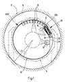
- FIG. 1 shows, as an example of a bracket 10 according to the invention, an inner bracket 10 'which can be mounted in a tube 12 with the aid of a robot 14.
- the robot 14 is only indicated by dashed lines in FIG. 1.
- the inner bracket 10 ' is shown in its state before assembly in the tube 12 and has a spirally wound strap band 16, the radius r 1 of which is smaller than the inner radius r 2 of the tube 12.
- a plurality of holders 18 are fastened one behind the other to the strap band 16, which point radially inwards.
- a tension lock 20 with a locking pin 24 locked by a locking template 22 is shown as the locking element 5 in the tensioned state as the tension lock 20.
- the tension lock 20 has an insertion opening 26 for inserting an inner band end 28 of the spirally curved strap band 16.
- an access section 30 of the strap band Arranged adjacent to this end 28 is an access section 30 of the strap band, which is spaced apart from the radially outer, adjacent turn of the strap band 16 by inserting the strap end 28 into the insertion opening 26 of the tension lock 20.
- the access section 30 can easily be gripped by robot grippers 32 (indicated by dashed lines) and the clamps 10, 10 ′ can be expanded to the radius r 2 of the tube 12.
- Fig. 2 the inner bracket 10 'shown in Fig. 1 is in the expanded state with the tension lock still tensioned 20 shown.
- the previously wound up in a spiral Strap band 16 is only in one section guided twice along the tube 12 and is now, rather forming a ring shape as a spiral, close to the inner tube wall 34 of the tube 12.
- the inside band end 28 of the strap band 16 is no longer in the Insertion opening 26 of the tension lock 20 and the latter End neighboring, released by the robot grippers Access section 30 of the strap band 16 is due to the Spring force of e.g. Stainless steel strap band no longer from the adjacent turn of the strap band 16 spaced.
- the Bride can 10, 10 'by loosening the locking template 22, e.g. by means of of a hammer 15 shown in dashed lines in FIG Robot 14, clamped in the tube.
- Fig. 3 shows a further embodiment of the inner bracket 10 'with a further embodiment of the tension lock 20 ''.
- This inner bracket 10 ' is instead of a robot gripper 32 with the help of one attached to the robot 14 Gear 33 expanded.
- the access section 30 of the strap band 16 ' lies on the radially outer adjacent turn of the strap band 16 ', which the Access section 30 spaced from the inner tube wall holds.
- a recess 118 in the Access section 30 adjacent turn of the strap band 16 'prevents contact with the gear 33 of the Robot 14.
- the through the adjacent turn of the strap band given distance between the inner tube wall 34 and Access section 30 prevents the gear 33 when Comb with the access section 30 with the inner tube wall comes into contact.
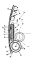
- the tension lock 20 is about fasteners 36 of its elongated Housing 38 on the fastening section 40 of the strap 16 fastened and has a first end portion 1 and a second end section 2.
- One as a coil spring 42 trained and acting as a compression spring of the snap fastener 20 through which the locking pin 24th is passed through, is from the housing 38 on the long sides enclosed in a trough shape.
- the first end 42 'of Spring 42 is in the first end region 1 of the tension lock 20 supported on an end wall 44 of the housing 38, the has a through opening 46 for the locking bolt 24. This is in the second end region 2 of the tension lock 20 Housing 38 open. In this second end area 2 of the Tension lock 20 is on the strap band 16 opposite The insertion opening 26 is arranged on the long side.
- the locking template 22 of the tension lock 20 is also on the long side opposite the strap band 16 37 of the housing 38 attached and is for example formed from a sheet of spring steel.
- the locking template 22 is designed such that a part 22 'of the locking template 22, which has a keyhole-shaped template opening 48 with a narrower opening part 48 'and another Has opening part 48 '' outside the housing 38 arranged in front of the end wall 44 and there in the direction of the strap band 16 is displaceable.
- the one against the first End region 1 of the snap fastener 20 aligned part of the locking pin 24 has a first annular groove 50 with reduced diameter compared to the locking pin 24 on.
- the state of the tension lock 20 is the locking bolt 24 through the through opening 46 of the end wall 44 and through passed the template opening 48 of the locking template 22 and the limitation of the narrower opening part 48 ' the template opening 48 engages in the first groove 50 of the Locking pin 24, whereby the locking pin 24 when tensioned Spring 42 locked and in its locked position is held.
- Locking pin 24 is in a second groove 52 of the locking pin 24 fixes a locking plate 54, via which a second End 42 '' of the coil spring 42 with respect to the Locking bolt 24 is supported.
- the locking plate 54 serves also the fixation of more between her and the Coil spring 42 attached to the locking pin 24 Elements such as the fixation of a freewheel 56 carrying carriage 58 and a blocking element 60 of the freewheel 56 supporting leaf spring 62.
- the carriage 58 fixed to the locking pin 24 has two Side walls 64 on the outside of the coil spring 42 against the second end region 2 of the tension lock 20 extend the first end region 1 of the tension lock 20 and against the first end region 1 against that Project strap strap 16 over coil spring 42.
- the over the coil spring 42 protruding parts 64 'of Side walls 64 have bearing openings 66 in which the blocking element 60 of the freewheel designed as a blocking arm 56 is rotatably mounted.
- the two on the spring 42 protruding parts 64 'of the side walls 64 are through a connecting plate 68 which is transverse to the coil spring spanned in their longitudinal direction, connected to each other.
- the connecting plate 68 forms together with the parts 64 'of the side walls 64 of the carriage 58 a guide element 70 of the freewheel 56.
- the freewheeling part of the strap band 16 is by this guide element 70 of the Freewheel 56 passed and is by the same in Area of the tension lock 20 at a minimum distance held to the fastening section 40 of the strap band 16.
- the leaf spring also attached to the locking pin 24 62 extends spanning the spring 42 in the longitudinal direction, from the end wall 44 opposite Side of the locking pin 24 to under the connecting plate 68 of the freewheel 56. It supports the rotatably mounted Blocking element 60 of the freewheel 56 and presses this resiliently against the strap band 16 between the blocking element 60 and connecting plate 68 passes through.
- Blocking portion 72 which is due to blocking holes 74 Has blocking edges 76 into which the blocking element 60 of the freewheel 56 can snap into place.
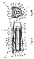
- the tension lock 20 is from the 4a and 4b shown in a partially relaxed state.
- the locking template 22 is in the direction of the strap band 16 moved so that the further opening part 48 "of the template opening 48 to the height of the through opening 46 of the side wall 44 is shifted, whereby the Locking bolt 24 unlocked and due to the spring tension has slipped into the interior of the housing 38.
- the most Locking pin 24 fixed elements such as the freewheel 56th load-bearing carriage 58, on which the blocking element 60 is fixed, and the blocking element 60 supporting Leaf spring 62 are with the locking pin 24 against the second End region 2 of the tension lock 20 moved.
- the Blocking element 60 engages in a blocking hole 74 of the Blocking section 72 of the strap band 16 and transmits over the carriage 58 onto the blocking element 60 transmitted force of the coil spring 42 on the Belt strap 16, which with the appropriate spring force under Compressive stress (arrow direction A) is set.
- Tension lock 20 is thus the strap strap 16, which already before unlocking the locking pin 24, as in Fig. 2 shown, rests against the inner tube wall 34, firmly - with the spring force which can be determined prior to the use of the clips 10, 10 ' - pressed against the inner tube wall 34 and the Bride 10, 10 'so firmly anchored in the tube 12.
- a tension lock 20 ' is shown, which is basically the same as the Tension lock 20, which in FIGS. 1 and 2 and 4a to 5b is shown.
- Locking pin 24 has a pivot pin 78 as a locking element 5.
- the pivot pin 78 is facing the end wall 44 End section 79 again with a first groove 50 provided between the bolt body 80 and bolt head 82nd lies and separates both.
- the bolt head 82 has two opposite sides millings 84 so that he approximates a bar shape.
- the millings 84 are dimensioned so that the bolt head 82 only in a defined Position of the pivot pin 78 through the through opening 46 of the end wall 44 fits through.
- the end wall 44 from three wall elements 44 '(Fig.5b) formed which has a rectangular through opening 46 through which the bolt head 82 in a horizontal position. Will the bolt head 82 through the passage opening 46 from the housing 38 stuck out and turned to a vertical position, parts of the wall elements 44 ′ of the end wall 44 thus engage the groove 50 behind the bolt head 82 and prevent the pivot pin 78 with the bolt head 82 through the through opening 46 of the end wall 44 back into the housing 38 slips.
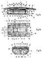
- FIG. 3 20 '' The further embodiment of the tension lock shown in FIG. 3 20 '' is more detailed in Figures 7a to 7c shown.
- the tension lock 20 is in principle constructed in the same way as the toggle fastener 20 ', which in the 6a to 6b is shown.
- the elongated housing 38 of the snap lock 20 '' is, however, instead via screws or bolts through rivets over the fastening elements 36 with the fastening section 40 of the Belt strap 16 connected. This has the advantage that Strap strap 16 with the strap 10, 10 ′ expanded in the fastening section 40 lies closer to the inner tube wall 34.
- a locking bar 100 is provided by two coil springs 42 is flanked.
- the end wall 44 of the housing 38 has a notch 102 through which to tension the tension lock 20 '' led through a nose 104 of the locking bar 100 becomes.
- the nose 104 is from the body 108 through a notch 106 of the locking bar 100 separately.
- the carriage 58 again has side walls 64, which is between the coil springs 42 and the housing 38 from the second end region 2 to the first End region 1 of the tension lock 20 "extend over the front wall 108, which in the second end region 2 of the Tension lock 20 "in an anchoring groove 110 of the Locking bar 100 is anchored, the carriage 58 is with the locking bar 100 and is coupled with this when releasing the locking of the locking bar 100 by the Coil springs 42 in the direction of the second end region 2 of the snap lock 20 ''.
- the side walls 64 of the Slide 58 protrude on the strap band 16 facing Side beyond the coil springs 42 and are in the both end regions 1, 2 by connecting plates 68, 68 ' connected with each other.
- the connecting plates 68, 68 ' form together with those arranged between them Coil springs 42 laterally from the side walls 64 overlapping guide plates 69, the guide element 70 of the freewheel 56.
- the guide plates 69 are of the coil springs 42 spaced that the strap 16 approximately linearly via the connecting plates 68, 68 'and passed freely under the guide plates 69 can be.
- the connecting plate 68 'in the first end region 1 of the Tension lock 20 '' has the guide plates on it 69 facing side and between the coil springs 42 a flange oriented into the interior of the housing 112 with a centrally arranged opening 114.
- the Blocking element 60 which in turn is in the form of a blocking arm is formed, extends through the opening 114 and is anchored behind the flange 112 against train. Via butt flanks 113, which are at the front 115 of the Apply flange, the blocking element 60 is against Pressure secured.
- the blocking element 60 protrudes in the direction of the second end region 2 of the tension lock 20 ′′ via the coil springs 42 and the connecting plates 68, 68 'against the strap band 16.
- the blocking element 60 gripped by a leaf spring 62, which the blocking element 60 resilient against the free-running Part of the strap band 16 presses.
- the leaf spring 62 is approximately parallel to the coil springs 42 and in the area the connecting plate 68 between the connecting plate 68 and coil springs 42 arranged.
- In the second end area 2 of the tension lock 20 ′′ has the leaf spring a vertically angled section 63 on the them by means of the coil springs 42 against the front wall 108 of the carriage 58 pressed and clamped there becomes.
- the strap band can also be designed differently be, the functional design of the Robot 14 plays a role.
- Fig. 8 shows a strap band 16 as for example together with a robot 14 shown in FIG Robot grippers 32 used to widen the clamps 10, 10 ' becomes.
- the band end 28 of the strap band 16 is as Insertion tab 28 'shaped to be inserted into the Insertion opening 26 of the tension lock 20, 20 'determined is.
- the access section is adjacent to the insertion tab 28 ' 30 arranged in this embodiment Access openings 84 for access by robot grippers 34 has.
- the blocking section 72 of the strap band 16, its position in the strap band 16 according to the inner circumference the tube 12 is selected is with blocking holes 74 provided, in which the blocking element 60 in the freewheel 56 of the snap lock 20 can snap into place.
- holder 18 are shown on a Holder section 86 of the strap band 16 attached.
- holder section 86 can have fastening means, e.g. in the form of the mounting holes shown here 88.
- fastening section 40 of the strap band 16 At the opposite end of the tape 28 End 29 of the strap band 16 is the fastening section 40 of the strap band 16, on which the tension lock 20, 20 '20' 'can be attached.
- Fastening the turnbuckle 20, 20 ', 20' ' are also 40 fastening openings in the fastening section 90 provided by which, for example, the fasteners 36 of the latches 20, 20 'reach through can, as shown in Figs. 4a to 6b is. But it can also be screws, bolts or other fasteners are inserted.
- FIG. 9 shows a second embodiment of a strap band 16 'shown e.g. can be used when the robot 14 instead of the robot gripper 32 for expanding the bracket 10, 10 'has a gear 33 with teeth 116, as shown in Fig. 3.
- the strap band 16 ' is basically the same as the strap band 16 from Fig. 8.
- holes 85 are provided instead of the engagement openings, with which the teeth 116 of the gear 33 mesh can. Is the gear 33 of the robot 14, in the expanding direction seen upstream of the tension lock 20, 20 ', 20' 'arranged as shown in Fig. 3, so instead of the access section 30 is the blocking section 72 arranged adjacent to the band end 28.
- the blocking openings 74 and the holes 85 each designed differently from each other.
- the strap band 16 'shown here is, for example Extension of the blocking openings 74 transversely to the longitudinal direction the strap band 16 larger than that of the holes 85, in the case shown here the teeth 116 of the gear 33 also with the blocking openings 74 in the blocking section 72 of the strap band 16 'can comb.
- an incision 118 in width of teeth 116 and along the central longitudinal axis 120 of the strap band 16 from the end 29 of the strap band 16 to Fastening section 40 is provided.
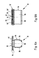
- FIGS. 10a and 10b of the holder 18 shown An embodiment is shown as an example in FIGS. 10a and 10b of the holder 18 shown, which for receiving of cables, pipes or similar elongated objects is attached to the strap band 16, as in the 1 to 3 is shown.
- the holder 18 has a fastening member 92 on that in the embodiment shown Is C-shaped, the towards each other facing flanks 92 'of the C-shaped fastening member 92 a holding element 94 for receiving the elongated Objects facing each other.
- the flanks 92 ' point approximately vertically into the C-shape of the fastener 92 protruding tabs 93, which in the mounting holes 88 in the holder section 86 of the strap band 16, 16 'intervene, for example, and preferably by bending smaller sections of the Flanks are formed.
- the C shape of the fastener 92 is designed such that the holding element 94 is removed from the holder section 86 of the strap band 16, 16 'is spaced and another section of the strap band 16 with play between the holding member 94 and the holder portion 86 the strap band 16, 16 'can be passed through.
- the Holding element 94 is designed in the form of two holding tongues 96, the end portions 98 hook-shaped towards each other are bent.
- the holding tongues 96 are resilient trained and include the objects to be held cliff-like.
- the bracket 10, 10 ' can also be used as Outside clip can be designed and it can for example can also be used without holder 18.
- a locking element 5 can instead of a locking pin 24, a pivot pin 78 or a locking bar 100 e.g. also a snap clip, a locking lever or the like may be provided. That too Blocking element 60 in freewheel 56 does not have to have a blocking arm but can just as well be the shape of a thorn have or designed in the form of several blocking teeth his.
- the position of the freewheel 56 with respect to the Spring 42 and the housing 38 of the snap lock 20th are not mandatory in the form shown.
- the spring force the spring 42 only has to be released when the latching element 5 is disengaged are transferred via freewheel to the belt band 16, 16 '.
- the holders 18 can also be different, e.g. designed as eyelets through which the elongated objects be threaded through.
- the holder 18 and the latch 20 can be used with bolts, screws, rivets, Plug connections or by welding or soldering be attached to the strap band 16, 16 '.
- Even the design of the blocking flanks 76 in the blocking section 72 of the Belt strap 16, 16 ' can be done in other ways than only through blocking holes 74, e.g. about incorporated paragraphs or hollows.
- the engagement openings 84 and holes 85 are in the access section 30 of the strap band 16 for example, hooks are also conceivable.
Landscapes
- Engineering & Computer Science (AREA)
- General Engineering & Computer Science (AREA)
- Physics & Mathematics (AREA)
- Mechanical Engineering (AREA)
- General Physics & Mathematics (AREA)
- Optics & Photonics (AREA)
- Clamps And Clips (AREA)
- Supports For Pipes And Cables (AREA)
- Load-Engaging Elements For Cranes (AREA)
- Auxiliary Devices For And Details Of Packaging Control (AREA)
- Flanged Joints, Insulating Joints, And Other Joints (AREA)
- Seal Device For Vehicle (AREA)
- Gripping Jigs, Holding Jigs, And Positioning Jigs (AREA)
- Absorbent Articles And Supports Therefor (AREA)
- Vehicle Body Suspensions (AREA)
- Hooks, Suction Cups, And Attachment By Adhesive Means (AREA)
- Basic Packing Technique (AREA)
- Arc Welding In General (AREA)
- Adornments (AREA)
- Orthopedics, Nursing, And Contraception (AREA)
- Prostheses (AREA)
- Materials For Medical Uses (AREA)
- Package Frames And Binding Bands (AREA)
Description
- Fig. 1
- einen Rohrquerschnitt mit einer ersten Ausführungsform einer mit Hilfe eines Roboters in dem Rohr montierbaren Innenbride vor der Montage mit einer ersten Ausführungsform eines Spannverschlusses und einem spiralförmig aufgewickeltem Bridenband;
- Fig. 2
- den Rohrquerschnitt und die Innenbride aus Fig. 1, wobei das Bridenband so aufgeweitet ist, dass es an der Rohrinnenwand anliegt;
- Fig. 3
- einen Ausschnitt aus einer zweiten Ausführungsform einer Innenbride, welche mit Hilfe eines zum in Fig. 1 dargestellten Roboter unterschiedlich ausgestalteten Roboters in einem Rohr montiert werden kann;
- Fig. 4a
- eine erste Ausführungsform eines Spannverschlusses mit Rastbolzen und Rastschablone, wie er in den Fig. 1 und 2 gezeigt ist, mit gespannter Feder in einem Schnitt in Längsrichtung;
- Fig. 4b
- den Spannverschluss aus Fig. 4a mit Blick auf die erste, die Rastschablone aufweisende Stirnseite;
- Fig. 5a
- den Spannverschluss aus Fig. 4a in analoger Darstellung mit verschobener Rastschablone, entriegeltem Rastbolzen und teilweise entspannter Feder;
- Fig. 5b
- den Spannverschluss aus Fig. 5a in analoger Darstellung zur Darstellung in Fig. 4b;
- Fig. 6a
- eine zweite Ausführungsform eines Spannverschlusses mit einem Drehbolzen als Rastelement und gespannter Feder in einem Schnitt in Längsrichtung;
- Fig. 6b
- den Spannverschluss aus Fig. 6a in analoger Darstellung zur Darstellung in den Fig. 4b und 5b;
- Fig. 7a
- eine dritte Ausführungsform eines Spannverschlusses mit einem Rastbalken als Rastelement und zwei gespannten Schraubenfedern in einem Schnitt in Längsrichtung;
- Fig. 7b
- den Spannverschluss aus Fig. 7a mit Blick vom Bridenband her
- Fig. 7c
- den Spannverschluss aus Fig. 7a in analoger Darstellung zur Darstellung in den Fig. 4b, 5b und 6b;
- Fig. 8
- eine erste Ausführungsform eines Bridenbandes einer mit Hilfe eines Roboters in einem Rohr montierbaren Innenbride;
- Fig. 9
- eine zweite Ausführungsform eines Bridenbandes einer mit Hilfe eines Roboters in einem Rohr montierbaren Innenbride;
- Fig. 10a
- einen am Bridenband befestigbaren Halter für die Aufnahme von langgestreckten Gegenständen mit Blick quer zum Bridenband;
- Fig. 10b
- den Halter aus Fig. 10a mit Blick in Richtung des Bridenbandes.
Claims (13)
- Bride mit einem zu einem Ring bzw. zu einer Spirale gebogenen Bridenband (16), das mittels eines mit einem lösbaren Rastelement (5) versehenen und einerseits mit einem Befestigungsabschnitt (40) und andererseits mit einem Blockierabschnitt (72) des Aridenbandes (16) zusammenwirkenden Spannverschlusses (20, 20', 20") unter Spannung setzbar ist, dadurch gekennzeichnet, dass am Befestigungsabschnitt (40) der mit einer Feder (42) versehene Spannverschluss (20, 20', 20'') befestigt ist, der Blockierabschnitt (72) zum Zusammenwirken mit einem Freilauf (56) des Spannverschlusses (20, 20', 20'') bestimmt ist, ein erstes Ende (42') der Feder (42) bezüglich des Befestigungsabschnittes (40) fest abgestützt ist, das Rastelement (5) dazu bestimmt ist, in Raststellung die Feder (42) in gespanntem Zustand zu halten, wobei ein mit dem Rastelement (5) zusammenwirkendes zweites Ende (42'') der Feder (42) derart mit dem Freilauf (56) zusammenwirkt, dass beim Ausrasten des Rastelementes (5) der Blockierabschnitt (72) des Bridenbandes (16) im Freilauf (56) festgehalten und das Bridenband (16) durch die deblockierte Feder (42) unter Spannung gesetzt wird.
- Bride nach Anspruch 1, dadurch gekennzeichnet, dass das Rastelement (5) ein Drehbolzen (78) ist, der so ausgestaltet ist, dass er durch eine Drehung, vorzugsweise um 90°, zum Ausrasten gebracht wird.
- Bride nach Anspruch 1, dadurch gekennzeichnet, dass das Rastelement (5) ein Rastbolzen (24) ist, der durch eine Rastschablone (22) in seiner Raststellung haltbar ist, und die Schablone (22) derart ausgestaltet ist, dass ein Verschieben der Schablone (22) zum Ausrasten des Rastbolzens (24) führt.
- Bride nach Anspruch 1, dadurch gekennzeichnet, dass das Rastelement (5) ein Rastbalken (100) ist, der durch eine an ihm angeordnete Nase (104) in Raststellung haltbar ist, wobei ein Verschieben der Nase (104) zum Ausrasten des Rastbalkens (100) führt.
- Bride nach einem der Ansprüche 1 bis 4, dadurch gekennzeichnet, dass der Blockierabschnitt (72) mit Blockierflanken (76) versehen ist, an denen zum Blokkieren des Bridenbandes (16) ein Blockierelement (60) des Freilaufs (56), vorzugsweise in Form eines Blokkierarms, angreifen kann.
- Bride nach einem der Ansprüche 1 bis 5, dadurch gekennzeichnet, dass der Spannverschluss (20, 20', 20") ein Gehäuse (38) aufweist, über dessen Befestigungselemente (36) der Spannverschluss (20, 20', 20'') am Befestigungsabschnitt (40) des Bridenbandes (16) befestigt ist und gegen dessen eine Stirnwand (44) das erste Ende (42') der Feder (42) fest abgestützt ist, wobei das zweiten Ende (42'') der Feder (42) mit einem den Freilauf (56) tragenden Schlitten (58) zusammenwirkt.
- Bride nach einem der Ansprüche 1 bis 6, dadurch gekennzeichnet, dass sie einen über ein Befestigungsglied (92) am Bridenband (16) befestigten Halter (18) mit einem Halteelement (94) für die Aufnahme von langgestreckten Gegenständen, insbesondere von Kabeln oder Rohren, aufweist, wobei das Befestigungsglied (92) das Halteelement (94) derart vom mit dem Befestigungsglied verbundenen Bridenband (16) beabstandet hält, dass zwischen dem Halteelement (94) und dem fest mit dem Halter (18) verbundenen Bridenband (16) ein weiterer Abschnitt des Bridenbandes (16) hindurchgeführt werden kann.
- Bride nach Anspruch 7, dadurch gekennzeichnet, dass das Halteelement (94) des Halters (18) klippartig mit zwei federnden Haltezungen (96) ausgestaltet ist und, dass vorzugsweise eine Vielzahl von Haltern (18) in festem Abstand hintereinander am Bridenband (16) angeordnet sind.
- Bride nach einem der Ansprüche 1 bis 8, dadurch gekennzeichnet, dass sie eine Innenbride (10') ist und dass das Bridenband (16) durch entriegeln des Spannverschlusses (20, 20', 20'') unter Druckspannung gesetzt wird, wobei die Knicksteifigkeit des Bridenbandes (16) so gewählt ist, dass es unter der aufgebrachten Druckspannung nicht knickt.
- Bride nach Anspruch 9, dadurch gekennzeichnet, dass sie an einem Abschnitt des Bridenbandes (16) von einem Roboter (14) gehalten werden kann und, dass das Bridenband (16) einen Zugriffsabschnitt (30) aufweist, der von einem Roboter (14) zum Aufweiten des Bridenbandes (16) ergriffen werden kann, so dass die Bride (10/10') mit Hilfe des Roboters (14) in einem Rohr (12) montiert werden kann.
- Bride nach Anspruch 10, dadurch gekennzeichnet, dass der Zugriffsabschnitt (30) einem innenliegenden Ende (28) des spiralförmig aufgewickelten Bridenbandes (16) benachbart ist und Eingreiföffnungen (84) für den Zugriff von Robotergreifern (32) aufweist und dass das Bandende 28, welches in Form einer Einführlasche (28') ausgestaltet ist, vor der Montage in eine dafür vorgesehene Einführöffnung (26) des Spannverschlusses (20, 20', 20'') eingeführt ist, wodurch der Zugriffsabschnitt (30) von der benachbarten Windung des Bridenbandes (16) beabstandet gehalten ist.
- Bride nach Anspruch 10, dadurch gekennzeichnet, dass der Zugriffsabschnitt (30) Löcher (85) für den Zugriff eines am Roboter angeordneten Zahnrades (33) aufweist und ein innenliegendes Ende (28) des spiralförmig aufgewickelten Bridenbandes (16), welches vorzugsweise in Form einer Einführlasche (28') ausgestaltet ist, vor der Montage insbesondere in eine dafür vorgesehene Öffnung (122) des Bridenbandes (16) eingeführt ist.
- Verwendung einer Bride gemäss den Ansprüchen 9 bis 12, zum Halten von langgestreckten Gegenständen, vorzugsweise von Kabeln und Rohren, in Rohrleitungsnetzen und insbesondere in nichtbegehbaren Rohren (12).
Priority Applications (2)
| Application Number | Priority Date | Filing Date | Title |
|---|---|---|---|
| EP98936058A EP1057053B1 (de) | 1998-02-17 | 1998-08-07 | Bride mit spannverschluss |
| SI9830109T SI1057053T1 (en) | 1998-02-17 | 1998-08-07 | Tightening strip with tension locking system |
Applications Claiming Priority (4)
| Application Number | Priority Date | Filing Date | Title |
|---|---|---|---|
| EP98102682 | 1998-02-17 | ||
| EP98102682A EP0936479A1 (de) | 1998-02-17 | 1998-02-17 | Bride mit Spannverschluss |
| EP98936058A EP1057053B1 (de) | 1998-02-17 | 1998-08-07 | Bride mit spannverschluss |
| PCT/CH1998/000331 WO1999042865A1 (de) | 1998-02-17 | 1998-08-07 | Bride mit spannverschluss |
Publications (2)
| Publication Number | Publication Date |
|---|---|
| EP1057053A1 EP1057053A1 (de) | 2000-12-06 |
| EP1057053B1 true EP1057053B1 (de) | 2001-11-14 |
Family
ID=8231429
Family Applications (2)
| Application Number | Title | Priority Date | Filing Date |
|---|---|---|---|
| EP98102682A Withdrawn EP0936479A1 (de) | 1998-02-17 | 1998-02-17 | Bride mit Spannverschluss |
| EP98936058A Expired - Lifetime EP1057053B1 (de) | 1998-02-17 | 1998-08-07 | Bride mit spannverschluss |
Family Applications Before (1)
| Application Number | Title | Priority Date | Filing Date |
|---|---|---|---|
| EP98102682A Withdrawn EP0936479A1 (de) | 1998-02-17 | 1998-02-17 | Bride mit Spannverschluss |
Country Status (25)
| Country | Link |
|---|---|
| US (1) | US6418591B1 (de) |
| EP (2) | EP0936479A1 (de) |
| JP (1) | JP3718762B2 (de) |
| KR (1) | KR100555120B1 (de) |
| CN (1) | CN1132033C (de) |
| AT (1) | ATE208907T1 (de) |
| AU (1) | AU746364B2 (de) |
| BR (1) | BR9815662A (de) |
| CA (1) | CA2321476C (de) |
| CZ (1) | CZ296620B6 (de) |
| DE (1) | DE59802180D1 (de) |
| DK (1) | DK1057053T3 (de) |
| ES (1) | ES2167918T3 (de) |
| HU (1) | HU222003B1 (de) |
| ID (1) | ID27472A (de) |
| IL (1) | IL137847A (de) |
| NO (1) | NO321684B1 (de) |
| NZ (1) | NZ506160A (de) |
| PL (1) | PL188117B1 (de) |
| PT (1) | PT1057053E (de) |
| RU (1) | RU2201548C2 (de) |
| SI (1) | SI1057053T1 (de) |
| SK (1) | SK286334B6 (de) |
| TR (1) | TR200002383T2 (de) |
| WO (1) | WO1999042865A1 (de) |
Families Citing this family (19)
| Publication number | Priority date | Publication date | Assignee | Title |
|---|---|---|---|---|
| EP0978743B1 (de) | 1998-08-07 | 2001-03-07 | KA-TE System AG | Vorrichtung zum Montieren einer Innenbride in einem nicht begehbaren Rohr |
| DE10100647A1 (de) * | 2001-01-09 | 2003-04-24 | Alcatel Sa | Kabelhalterung |
| EP1223446A1 (de) * | 2001-01-15 | 2002-07-17 | KA-TE System AG | Verfahren zum Verlegen von Datenübertragungskabeln in Rohrleitungssystemen |
| DE10111960B4 (de) | 2001-03-13 | 2004-05-06 | CCS Technology, Inc., Wilmington | Kanal- oder Rohrsystem sowie Verfahren zur Installation eines Kabels oder Leerrohrs in einem Kanal- oder Rohrsystem |
| US6644892B2 (en) * | 2001-06-08 | 2003-11-11 | Nihonhume Corporation | Method for attaching cable and cable holder |
| WO2003004926A2 (de) | 2001-07-01 | 2003-01-16 | Gustav Trippe | Fixierung von verlegeobjekten, insbesondere von glasfaserkabeln, im deckenbereich von unterirdischen rohrwerken mittels klebetechnik |
| EP1291991A3 (de) * | 2001-09-10 | 2005-09-28 | Alcatel | Verfahren zum einordnen eines rohrförmigen elements in einem unzugänglichen Hohlraum |
| UA14944U (en) * | 2003-02-25 | 2006-06-15 | Viktor Illich Klievtsov | Clamp for parts connections |
| DE202004009156U1 (de) * | 2004-06-09 | 2005-10-27 | Keitz, Andreas Von | Nottrennbare Lichtleitung |
| CN1303351C (zh) * | 2004-06-17 | 2007-03-07 | 上海交通大学 | 排水管道内光缆支撑卡圈的定位方法 |
| KR200465230Y1 (ko) | 2011-01-19 | 2013-02-08 | 김오수 | 싸개형 히터의 클램프 |
| DE102011012338B4 (de) * | 2011-02-24 | 2020-10-15 | Gerald Preuß | Einrichtung zum Verlegen von Kabeln in Kanälen und zum gleichzeitigen Sanieren der Kanalwandung |
| KR20140137010A (ko) * | 2012-03-22 | 2014-12-01 | 내쇼날 오일웰 파르코 노르웨이 에이에스 | 케이블용 지지 장치 및 이를 이용한 케이블 지지 방법 |
| US20190136640A1 (en) * | 2016-06-10 | 2019-05-09 | Halliburton Energy Services, Inc. | Telemetry systems for tubulars |
| CZ307979B6 (cs) * | 2018-07-30 | 2019-09-25 | gwb.cz s.r.o. | Potrubní kabelová upínka a sestava zařízení pro její instalaci |
| CZ308481B6 (cs) * | 2019-08-14 | 2020-09-09 | gwb.cz s.r.o. | Způsob instalace potrubní kabelové upínky s opakovaným dopínáním upínacího pásku a instalační zařízení k jeho provádění |
| CN111677953A (zh) * | 2020-07-17 | 2020-09-18 | 缔柯圣(苏州)阀门管件制造有限公司 | 一种喉箍锁扣装置 |
| CN112630917B (zh) * | 2021-01-20 | 2021-09-14 | 南京升平通信设备有限公司 | 一种便于收放线的光纤配线架 |
| EP4487043A1 (de) * | 2022-02-28 | 2025-01-08 | Pipetronics GmbH & Co. KG | Arretierungsvorrichtung für eine im durchmesser veränderbare dichtungsmanschette |
Family Cites Families (16)
| Publication number | Priority date | Publication date | Assignee | Title |
|---|---|---|---|---|
| US2550575A (en) * | 1945-06-11 | 1951-04-24 | Chicago Eye Shield Company | Adjustable headband construction |
| US3474832A (en) * | 1967-01-30 | 1969-10-28 | James H Broadhead | Apparatus for sealing pipe from within |
| US4395009A (en) * | 1981-05-28 | 1983-07-26 | The Boeing Company | Raceway clamp |
| GB2129627B (en) * | 1982-09-22 | 1986-12-10 | Water Res Centre | Installation of communications cables |
| EP0152408B1 (de) * | 1983-08-03 | 1987-12-16 | Owens-Corning Fiberglas Corporation | Methode zum einsetzen einer membrane in eine leitung |
| US4589447A (en) | 1983-08-03 | 1986-05-20 | Owens-Corning Fiberglas Corporation | Method of depositing a membrane within a conduit |
| GB2154808B (en) | 1984-02-21 | 1987-09-09 | Water Res Centre | Installation of communications cables |
| DE4103847A1 (de) * | 1991-02-08 | 1992-08-13 | Eickhoff Geb | Verfahren und vorrichtung zum auskleiden von langgestreckten oeffnungen mit kreisfoermigen und nicht kreisfoermigen querschnitten, insbesondere fuer den kanal- und tunnelbau |
| US5170540A (en) * | 1991-07-15 | 1992-12-15 | Hans Oetiker | Adjustable screw-type clamp |
| WO1993006986A1 (en) | 1991-10-02 | 1993-04-15 | Rib Loc Australia Pty. Ltd. | Loop machine for helically winding strip |
| US5499430A (en) * | 1994-08-10 | 1996-03-19 | Strazar; Andrew A. | Hose clamp with supplemental holding fingers |
| FR2728326B1 (fr) * | 1994-12-14 | 1997-05-23 | Calmettes Lionel | Collier de serrage d'une piece tubulaire |
| DE59704861D1 (de) * | 1996-12-18 | 2001-11-15 | Volkswagen Ag | Spannband |
| DE19653005B4 (de) * | 1996-12-19 | 2005-11-24 | Hans Oetiker Ag Maschinen- Und Apparatefabrik | Schlauchschelle |
| DE19701526C1 (de) * | 1997-01-17 | 1998-09-03 | Armstrong Insulation Products | Rohrbefestigungselement |
| US5930872A (en) * | 1997-09-22 | 1999-08-03 | The Gates Corporation | Device for mounting and deploying a shrinkable clamp |
-
1998
- 1998-02-17 EP EP98102682A patent/EP0936479A1/de not_active Withdrawn
- 1998-08-07 AT AT98936058T patent/ATE208907T1/de active
- 1998-08-07 EP EP98936058A patent/EP1057053B1/de not_active Expired - Lifetime
- 1998-08-07 NZ NZ506160A patent/NZ506160A/en unknown
- 1998-08-07 AU AU85269/98A patent/AU746364B2/en not_active Ceased
- 1998-08-07 WO PCT/CH1998/000331 patent/WO1999042865A1/de not_active Ceased
- 1998-08-07 PT PT98936058T patent/PT1057053E/pt unknown
- 1998-08-07 BR BR9815662-4A patent/BR9815662A/pt not_active IP Right Cessation
- 1998-08-07 TR TR2000/02383T patent/TR200002383T2/xx unknown
- 1998-08-07 RU RU2000123773/06A patent/RU2201548C2/ru not_active IP Right Cessation
- 1998-08-07 ID IDW20001842A patent/ID27472A/id unknown
- 1998-08-07 CN CN988139561A patent/CN1132033C/zh not_active Expired - Fee Related
- 1998-08-07 KR KR1020007008974A patent/KR100555120B1/ko not_active Expired - Fee Related
- 1998-08-07 ES ES98936058T patent/ES2167918T3/es not_active Expired - Lifetime
- 1998-08-07 US US09/601,284 patent/US6418591B1/en not_active Expired - Lifetime
- 1998-08-07 DE DE59802180T patent/DE59802180D1/de not_active Expired - Lifetime
- 1998-08-07 SI SI9830109T patent/SI1057053T1/xx unknown
- 1998-08-07 HU HU0100636A patent/HU222003B1/hu not_active IP Right Cessation
- 1998-08-07 CZ CZ20003016A patent/CZ296620B6/cs not_active IP Right Cessation
- 1998-08-07 SK SK1207-2000A patent/SK286334B6/sk not_active IP Right Cessation
- 1998-08-07 IL IL13784798A patent/IL137847A/en not_active IP Right Cessation
- 1998-08-07 PL PL98342452A patent/PL188117B1/pl unknown
- 1998-08-07 JP JP2000532745A patent/JP3718762B2/ja not_active Expired - Fee Related
- 1998-08-07 CA CA002321476A patent/CA2321476C/en not_active Expired - Fee Related
- 1998-08-07 DK DK98936058T patent/DK1057053T3/da active
-
2000
- 2000-08-17 NO NO20004125A patent/NO321684B1/no not_active IP Right Cessation
Also Published As
Similar Documents
| Publication | Publication Date | Title |
|---|---|---|
| EP1057053A1 (de) | Bride mit spannverschluss | |
| DE3447693A1 (de) | Selbstsperrendes flaches klemmband | |
| WO2007135138A1 (de) | Vorrichtung zum verbinden zweier mit flanschen versehener rohr- oder schlauchenden | |
| DE102017120867A1 (de) | Winkelverbinder für Montageschienen | |
| DE112010002322T5 (de) | Selbst zentrierendes Klebeband | |
| DE4304239A1 (de) | Befestigungsvorrichtung für Zubehör an Rohren und Stangen | |
| DE69401399T2 (de) | Rohrschelle | |
| DE102018110598A1 (de) | Direktmontage-Rohrschelle | |
| DE102012103815A1 (de) | Verzurrhakenelement sowie System zum Verzurren von Ladungen auf Ladeflächen, insbesondere zur Befestigung von Ladungen auf Transportblechen | |
| DE102004045993B4 (de) | Rohrschelle | |
| DE202012100235U1 (de) | Halter zum Halten eines Aggregates einer Abgasreinigungsanlage sowie Baukastensystem zum Erstellen eines derartigen Halters | |
| AT411052B (de) | Befestigungsbinder | |
| WO2024165448A1 (de) | Halteelement zum fixieren der kabel einer photovoltaikanlage | |
| DE102015101607B3 (de) | Befestigungsmittel zum Sichern eines Wellschlauchs an einer Muffe | |
| DE102017008327A1 (de) | V-Band-Schelle | |
| DE19738348B4 (de) | Vorrichtung zur Verbindung zweier Bauteile | |
| DE102004054336B4 (de) | Anordnung und Verfahren zum Verbinden von rohrförmigen Elementen | |
| EP1930212B1 (de) | Ladungssicherungswinkel | |
| DE102009043906A1 (de) | Halter für ein Fahrradschloss | |
| DE102007025191A1 (de) | Rohrschelle | |
| DE1650945C3 (de) | Befestigungsvorrichtung | |
| EP1050704A2 (de) | Rohrschelle | |
| EP3855055A1 (de) | Rohrschelle | |
| DE202008002830U1 (de) | Spannelement zum Verspannen von Schlingen | |
| DE19639132A1 (de) | Rohrschelle |
Legal Events
| Date | Code | Title | Description |
|---|---|---|---|
| PUAI | Public reference made under article 153(3) epc to a published international application that has entered the european phase |
Free format text: ORIGINAL CODE: 0009012 |
|
| 17P | Request for examination filed |
Effective date: 20000728 |
|
| AK | Designated contracting states |
Kind code of ref document: A1 Designated state(s): AT BE CH CY DE DK ES FI FR GB GR IE IT LI LU MC NL PT SE |
|
| AX | Request for extension of the european patent |
Free format text: AL PAYMENT 20000728;LT PAYMENT 20000728;LV PAYMENT 20000728;MK PAYMENT 20000728;RO PAYMENT 20000728;SI PAYMENT 20000728 |
|
| GRAG | Despatch of communication of intention to grant |
Free format text: ORIGINAL CODE: EPIDOS AGRA |
|
| 17Q | First examination report despatched |
Effective date: 20010207 |
|
| GRAG | Despatch of communication of intention to grant |
Free format text: ORIGINAL CODE: EPIDOS AGRA |
|
| GRAH | Despatch of communication of intention to grant a patent |
Free format text: ORIGINAL CODE: EPIDOS IGRA |
|
| GRAH | Despatch of communication of intention to grant a patent |
Free format text: ORIGINAL CODE: EPIDOS IGRA |
|
| GRAA | (expected) grant |
Free format text: ORIGINAL CODE: 0009210 |
|
| AK | Designated contracting states |
Kind code of ref document: B1 Designated state(s): AT BE CH CY DE DK ES FI FR GB GR IE IT LI LU MC NL PT SE |
|
| AX | Request for extension of the european patent |
Free format text: AL PAYMENT 20000728;LT PAYMENT 20000728;LV PAYMENT 20000728;MK PAYMENT 20000728;RO PAYMENT 20000728;SI PAYMENT 20000728 |
|
| REF | Corresponds to: |
Ref document number: 208907 Country of ref document: AT Date of ref document: 20011115 Kind code of ref document: T |
|
| REG | Reference to a national code |
Ref country code: CH Ref legal event code: EP |
|
| REG | Reference to a national code |
Ref country code: CH Ref legal event code: NV Representative=s name: PATENTANWAELTE SCHAAD, BALASS, MENZL & PARTNER AG |
|
| REG | Reference to a national code |
Ref country code: IE Ref legal event code: FG4D Free format text: GERMAN |
|
| REF | Corresponds to: |
Ref document number: 59802180 Country of ref document: DE Date of ref document: 20011220 |
|
| REG | Reference to a national code |
Ref country code: GB Ref legal event code: IF02 |
|
| GBT | Gb: translation of ep patent filed (gb section 77(6)(a)/1977) |
Effective date: 20020117 |
|
| ET | Fr: translation filed | ||
| REG | Reference to a national code |
Ref country code: DK Ref legal event code: T3 |
|
| REG | Reference to a national code |
Ref country code: PT Ref legal event code: SC4A Free format text: AVAILABILITY OF NATIONAL TRANSLATION Effective date: 20020204 |
|
| REG | Reference to a national code |
Ref country code: ES Ref legal event code: FG2A Ref document number: 2167918 Country of ref document: ES Kind code of ref document: T3 |
|
| REG | Reference to a national code |
Ref country code: GR Ref legal event code: EP Ref document number: 20010402630 Country of ref document: GR |
|
| PGFP | Annual fee paid to national office [announced via postgrant information from national office to epo] |
Ref country code: MC Payment date: 20020823 Year of fee payment: 5 |
|
| PGFP | Annual fee paid to national office [announced via postgrant information from national office to epo] |
Ref country code: IE Payment date: 20020827 Year of fee payment: 5 |
|
| PGFP | Annual fee paid to national office [announced via postgrant information from national office to epo] |
Ref country code: GR Payment date: 20020828 Year of fee payment: 5 |
|
| PGFP | Annual fee paid to national office [announced via postgrant information from national office to epo] |
Ref country code: CY Payment date: 20020831 Year of fee payment: 5 |
|
| PLBE | No opposition filed within time limit |
Free format text: ORIGINAL CODE: 0009261 |
|
| STAA | Information on the status of an ep patent application or granted ep patent |
Free format text: STATUS: NO OPPOSITION FILED WITHIN TIME LIMIT |
|
| 26N | No opposition filed | ||
| PG25 | Lapsed in a contracting state [announced via postgrant information from national office to epo] |
Ref country code: IE Free format text: LAPSE BECAUSE OF NON-PAYMENT OF DUE FEES Effective date: 20030807 |
|
| PG25 | Lapsed in a contracting state [announced via postgrant information from national office to epo] |
Ref country code: MC Free format text: LAPSE BECAUSE OF NON-PAYMENT OF DUE FEES Effective date: 20030831 Ref country code: CY Free format text: LAPSE BECAUSE OF NON-PAYMENT OF DUE FEES Effective date: 20030831 |
|
| PG25 | Lapsed in a contracting state [announced via postgrant information from national office to epo] |
Ref country code: GR Free format text: LAPSE BECAUSE OF NON-PAYMENT OF DUE FEES Effective date: 20040303 |
|
| LTLA | Lt: lapse of european patent or patent extension |
Effective date: 20030807 |
|
| REG | Reference to a national code |
Ref country code: IE Ref legal event code: MM4A |
|
| REG | Reference to a national code |
Ref country code: PT Ref legal event code: PC4A Owner name: FAST ROBOT AG, CH Effective date: 20100810 |
|
| REG | Reference to a national code |
Ref country code: ES Ref legal event code: PC2A Owner name: FAST ROBOT AG Effective date: 20110404 |
|
| PGFP | Annual fee paid to national office [announced via postgrant information from national office to epo] |
Ref country code: LU Payment date: 20130822 Year of fee payment: 16 |
|
| PGFP | Annual fee paid to national office [announced via postgrant information from national office to epo] |
Ref country code: ES Payment date: 20130829 Year of fee payment: 16 Ref country code: FI Payment date: 20130813 Year of fee payment: 16 Ref country code: CH Payment date: 20130807 Year of fee payment: 16 Ref country code: DE Payment date: 20130821 Year of fee payment: 16 Ref country code: NL Payment date: 20130815 Year of fee payment: 16 Ref country code: SE Payment date: 20130821 Year of fee payment: 16 Ref country code: DK Payment date: 20130821 Year of fee payment: 16 |
|
| PGFP | Annual fee paid to national office [announced via postgrant information from national office to epo] |
Ref country code: FR Payment date: 20130823 Year of fee payment: 16 Ref country code: GB Payment date: 20130821 Year of fee payment: 16 |
|
| PGFP | Annual fee paid to national office [announced via postgrant information from national office to epo] |
Ref country code: IT Payment date: 20130828 Year of fee payment: 16 |
|
| PGFP | Annual fee paid to national office [announced via postgrant information from national office to epo] |
Ref country code: BE Payment date: 20130823 Year of fee payment: 16 |
|
| PGFP | Annual fee paid to national office [announced via postgrant information from national office to epo] |
Ref country code: PT Payment date: 20140210 Year of fee payment: 17 |
|
| REG | Reference to a national code |
Ref country code: DE Ref legal event code: R119 Ref document number: 59802180 Country of ref document: DE |
|
| REG | Reference to a national code |
Ref country code: NL Ref legal event code: V1 Effective date: 20150301 |
|
| REG | Reference to a national code |
Ref country code: DK Ref legal event code: EBP Effective date: 20140831 |
|
| PG25 | Lapsed in a contracting state [announced via postgrant information from national office to epo] |
Ref country code: LU Free format text: LAPSE BECAUSE OF NON-PAYMENT OF DUE FEES Effective date: 20140807 |
|
| REG | Reference to a national code |
Ref country code: CH Ref legal event code: PL Ref country code: SE Ref legal event code: EUG |
|
| GBPC | Gb: european patent ceased through non-payment of renewal fee |
Effective date: 20140807 |
|
| PG25 | Lapsed in a contracting state [announced via postgrant information from national office to epo] |
Ref country code: FI Free format text: LAPSE BECAUSE OF NON-PAYMENT OF DUE FEES Effective date: 20140807 Ref country code: NL Free format text: LAPSE BECAUSE OF NON-PAYMENT OF DUE FEES Effective date: 20150301 Ref country code: CH Free format text: LAPSE BECAUSE OF NON-PAYMENT OF DUE FEES Effective date: 20140831 Ref country code: LI Free format text: LAPSE BECAUSE OF NON-PAYMENT OF DUE FEES Effective date: 20140831 Ref country code: BE Free format text: LAPSE BECAUSE OF NON-PAYMENT OF DUE FEES Effective date: 20140831 Ref country code: IT Free format text: LAPSE BECAUSE OF NON-PAYMENT OF DUE FEES Effective date: 20140807 |
|
| REG | Reference to a national code |
Ref country code: DE Ref legal event code: R119 Ref document number: 59802180 Country of ref document: DE Effective date: 20150303 |
|
| PG25 | Lapsed in a contracting state [announced via postgrant information from national office to epo] |
Ref country code: SE Free format text: LAPSE BECAUSE OF NON-PAYMENT OF DUE FEES Effective date: 20140808 |
|
| REG | Reference to a national code |
Ref country code: FR Ref legal event code: ST Effective date: 20150430 |
|
| PG25 | Lapsed in a contracting state [announced via postgrant information from national office to epo] |
Ref country code: GB Free format text: LAPSE BECAUSE OF NON-PAYMENT OF DUE FEES Effective date: 20140807 Ref country code: DE Free format text: LAPSE BECAUSE OF NON-PAYMENT OF DUE FEES Effective date: 20150303 Ref country code: DK Free format text: LAPSE BECAUSE OF NON-PAYMENT OF DUE FEES Effective date: 20140831 |
|
| PG25 | Lapsed in a contracting state [announced via postgrant information from national office to epo] |
Ref country code: FR Free format text: LAPSE BECAUSE OF NON-PAYMENT OF DUE FEES Effective date: 20140901 |
|
| REG | Reference to a national code |
Ref country code: ES Ref legal event code: FD2A Effective date: 20150925 |
|
| PG25 | Lapsed in a contracting state [announced via postgrant information from national office to epo] |
Ref country code: ES Free format text: LAPSE BECAUSE OF NON-PAYMENT OF DUE FEES Effective date: 20140808 |
|
| REG | Reference to a national code |
Ref country code: PT Ref legal event code: MM4A Free format text: LAPSE DUE TO NON-PAYMENT OF FEES Effective date: 20160208 |
|
| PG25 | Lapsed in a contracting state [announced via postgrant information from national office to epo] |
Ref country code: PT Free format text: LAPSE BECAUSE OF NON-PAYMENT OF DUE FEES Effective date: 20160208 |
|
| PGFP | Annual fee paid to national office [announced via postgrant information from national office to epo] |
Ref country code: AT Payment date: 20170822 Year of fee payment: 20 |
|
| REG | Reference to a national code |
Ref country code: AT Ref legal event code: MK07 Ref document number: 208907 Country of ref document: AT Kind code of ref document: T Effective date: 20180807 |