EP0152408B1 - Methode zum einsetzen einer membrane in eine leitung - Google Patents
Methode zum einsetzen einer membrane in eine leitung Download PDFInfo
- Publication number
- EP0152408B1 EP0152408B1 EP19840902317 EP84902317A EP0152408B1 EP 0152408 B1 EP0152408 B1 EP 0152408B1 EP 19840902317 EP19840902317 EP 19840902317 EP 84902317 A EP84902317 A EP 84902317A EP 0152408 B1 EP0152408 B1 EP 0152408B1
- Authority
- EP
- European Patent Office
- Prior art keywords
- conduit
- coiled member
- coiled
- damaged section
- sleeve
- Prior art date
- Legal status (The legal status is an assumption and is not a legal conclusion. Google has not performed a legal analysis and makes no representation as to the accuracy of the status listed.)
- Expired
Links
- 238000000034 method Methods 0.000 title claims abstract description 14
- 239000012528 membrane Substances 0.000 title abstract description 3
- 238000000151 deposition Methods 0.000 title abstract 2
- 239000011152 fibreglass Substances 0.000 claims description 2
- 238000003780 insertion Methods 0.000 description 6
- 230000037431 insertion Effects 0.000 description 6
- 239000000463 material Substances 0.000 description 5
- 230000006835 compression Effects 0.000 description 2
- 238000007906 compression Methods 0.000 description 2
- 239000003365 glass fiber Substances 0.000 description 2
- 239000004593 Epoxy Substances 0.000 description 1
- 238000005452 bending Methods 0.000 description 1
- 229920005549 butyl rubber Polymers 0.000 description 1
- 230000003247 decreasing effect Effects 0.000 description 1
- 230000007547 defect Effects 0.000 description 1
- 239000002990 reinforced plastic Substances 0.000 description 1
- 230000003014 reinforcing effect Effects 0.000 description 1
- 239000011347 resin Substances 0.000 description 1
- 229920005989 resin Polymers 0.000 description 1
- 238000007789 sealing Methods 0.000 description 1
Images
Classifications
-
- F—MECHANICAL ENGINEERING; LIGHTING; HEATING; WEAPONS; BLASTING
- F16—ENGINEERING ELEMENTS AND UNITS; GENERAL MEASURES FOR PRODUCING AND MAINTAINING EFFECTIVE FUNCTIONING OF MACHINES OR INSTALLATIONS; THERMAL INSULATION IN GENERAL
- F16L—PIPES; JOINTS OR FITTINGS FOR PIPES; SUPPORTS FOR PIPES, CABLES OR PROTECTIVE TUBING; MEANS FOR THERMAL INSULATION IN GENERAL
- F16L11/00—Hoses, i.e. flexible pipes
- F16L11/04—Hoses, i.e. flexible pipes made of rubber or flexible plastics
- F16L11/10—Hoses, i.e. flexible pipes made of rubber or flexible plastics with reinforcements not embedded in the wall
-
- E—FIXED CONSTRUCTIONS
- E03—WATER SUPPLY; SEWERAGE
- E03F—SEWERS; CESSPOOLS
- E03F3/00—Sewer pipe-line systems
- E03F3/06—Methods of, or installations for, laying sewer pipes
-
- F—MECHANICAL ENGINEERING; LIGHTING; HEATING; WEAPONS; BLASTING
- F16—ENGINEERING ELEMENTS AND UNITS; GENERAL MEASURES FOR PRODUCING AND MAINTAINING EFFECTIVE FUNCTIONING OF MACHINES OR INSTALLATIONS; THERMAL INSULATION IN GENERAL
- F16L—PIPES; JOINTS OR FITTINGS FOR PIPES; SUPPORTS FOR PIPES, CABLES OR PROTECTIVE TUBING; MEANS FOR THERMAL INSULATION IN GENERAL
- F16L55/00—Devices or appurtenances for use in, or in connection with, pipes or pipe systems
- F16L55/16—Devices for covering leaks in pipes or hoses, e.g. hose-menders
- F16L55/162—Devices for covering leaks in pipes or hoses, e.g. hose-menders from inside the pipe
- F16L55/163—Devices for covering leaks in pipes or hoses, e.g. hose-menders from inside the pipe a ring, a band or a sleeve being pressed against the inner surface of the pipe
-
- G—PHYSICS
- G02—OPTICS
- G02B—OPTICAL ELEMENTS, SYSTEMS OR APPARATUS
- G02B6/00—Light guides; Structural details of arrangements comprising light guides and other optical elements, e.g. couplings
- G02B6/46—Processes or apparatus adapted for installing or repairing optical fibres or optical cables
- G02B6/50—Underground or underwater installation; Installation through tubing, conduits or ducts
- G02B6/508—Fixation devices in ducts for drawing cables
-
- E—FIXED CONSTRUCTIONS
- E03—WATER SUPPLY; SEWERAGE
- E03F—SEWERS; CESSPOOLS
- E03F3/00—Sewer pipe-line systems
- E03F3/06—Methods of, or installations for, laying sewer pipes
- E03F2003/065—Refurbishing of sewer pipes, e.g. by coating, lining
Definitions
- This invention relates to a method of repairing a conduit having a damaged section in the form of holes, cracks and the like.
- the method of this invention is employable in any size conduit employed for any purpose. It is particularly suitable for use in conduit of from about 50.8 mm to about 381. mm (2 to about 15 inches) in diameter which conduit is inaccessible, such as a sewer line, but which conduit has an access opening thereinto.
- Any suitable coiled member, or spring, can be employed.
- One particularly suitable coiled member is made of fiberglass reinforced resin formed with a spiral slice.
- Suitable coiled members can be made from FRP (fibrous glass reinforced plastic) pipe using, for example, A. O. Smith Red Thread FRP or Grenn Thread glass fiber reinforce epoxy pipe.
- FRP fibrous glass reinforced plastic
- Such a member will comprise a continuous coiled flat band of any suitable length, will have a band width of from about 25.4 mm to about 254. mm (1 to about 10 inches) and a coil thickness of from about 2.54 mm to about 12.7 mm (0.100 to about 0.500 inch).
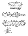
- the coiled member will have terminals 4 and 5 in which are positioned openings 6 and 7, respectively.
- the coiled member can have either a right or left hand pitch.
- the flat sections are preferably rectangular.
- the coiled member will have a diameter in its relaxed position greater than the internal diameter of the conduit into which it is to be inserted.
- the coiled member is introduced into the conduit in a torsionally loaded, or twisted and elongated condition, from which condition it is released after positioning a flexible sleeve and after insertion to expand outwardly and to exert a pressure against the flexible sleeve and the internal wall of the conduit.
- the coiled member can be designed to exert an desired pressure P according to the formula: wherein:
- a coiled member spirally cut from FRP pipe and encased in a 2.38125 mm (0.09375 inch) elastomeric membrane as hereinafter discussed. Assume insertion in a 10.16 mm (4 inch) internal diameter conduit.
- the coiled member will have a strained radius of 48.4124 mm (1.906 inches) and, assuming a section thickness of the coiled member as 2.794 mm (0.110 inch) and a tensile modulus of 2.07xlO' O pascals (3x10 6 psi), the pressure which will be exerted against the sleeve and the inner wall of the pipe will be 1.29x10 5 pascals (4.03 psig).
- the coiled member can be of any suitable thickness. Coiled members which develop about 6.9x 10 4 pascals (10 psi) against the sleeve and the internal wall of the pipe are generally satisfactory.
- the coiled member can be positioned within the conduit in any suitable manner.
- One carrier, or insertion device is shown in Figure 2.
- device 10 comprising rod 11, fixed bushing 12 and movable bushing 13.
- Rod 11 has at its one end attachment means, for example, a ring 14 affixed thereto. While bushing 12 is fixed, bushing 13 is free to rotate and move longitudinally along rod 11 in helix 15. Each of bushings 12 and 13 have studs 16 and 17, respectively, positioned therein. Bushing 13 is also adapted with set screw 18 for fixedly positing the free bushing along the length of the rod as described hereinafter.
- the pitch of the helix 15 on rod 11 substantially equal to that of the coiled member in order to obtain the correct dynamic behavior of the coiled member upon release as hereinafter described.
- bushing 13 has a downward projection 20 such that when bushing 13 moves towards bushing 12 as hereinafter described bushing 13 rotates helically.
- the coiled member is encompassed with a sleeve such that upon placement of the combination within the conduit, the sleeve is positioned between the coiled member and the inner conduit wall.
- the sleeve can be comprised of any suitable material, it will preferably be comprised of a flexible material such as vulcanized butyl rubber or any material inert to the material transported in the conduit.
- FIG. 3 there is illustrated the positioning of the coiled member on the insertion device.
- the coiled member 2 is slipped over the insertion device 10 with openings 6 and 7 positioned on studs 16 and 17.
- the free bushing 13 is then rotated outwardly along the length of the rod 11 and away from bushing 12, thus producing a simultaneous decrease in diameter and increase in length of the coiled member.
- the free bushing 13 is locked into position in the twisted coil state by lock-release mechanism, or set screw 18.
- the sleeve 21 is placed over any portion of the twisted coil member and the entire mechanism is placed in the conduit.
- the mechanism can be positioned in the conduit by pulling it thereinto by means affixed to ring 14.
- ths lock-release mechanism on bushing 13 is released.
- the freed bushing then moves towards the fixed bushing, the coiled member untwists and expands outward into a position of compression against the sleeve and the wall of the conduit.
- momentum carries the slots 6 and 7 off of studs 16 and 17, with the sleeve positioned between the coiled member and the inner wall of the pipe.
- the insertion device is then withdrawn leaving the coiled member in outward compression to force the sleeve in sealing arrangement against any defect which may have been present in the conduit.
- This invention is applicable to the repair of underground conduit such as sewerlines, pipelines and the like.
Landscapes
- Engineering & Computer Science (AREA)
- General Engineering & Computer Science (AREA)
- Mechanical Engineering (AREA)
- Physics & Mathematics (AREA)
- General Physics & Mathematics (AREA)
- Optics & Photonics (AREA)
- Health & Medical Sciences (AREA)
- Life Sciences & Earth Sciences (AREA)
- Hydrology & Water Resources (AREA)
- Public Health (AREA)
- Water Supply & Treatment (AREA)
- Pipe Accessories (AREA)
- Sewage (AREA)
- Lining Or Joining Of Plastics Or The Like (AREA)
Claims (5)
Priority Applications (1)
| Application Number | Priority Date | Filing Date | Title |
|---|---|---|---|
| AT84902317T ATE31445T1 (de) | 1983-08-03 | 1984-05-31 | Methode zum einsetzen einer membrane in eine leitung. |
Applications Claiming Priority (2)
| Application Number | Priority Date | Filing Date | Title |
|---|---|---|---|
| US51993983A | 1983-08-03 | 1983-08-03 | |
| US519939 | 1983-08-03 |
Publications (2)
| Publication Number | Publication Date |
|---|---|
| EP0152408A1 EP0152408A1 (de) | 1985-08-28 |
| EP0152408B1 true EP0152408B1 (de) | 1987-12-16 |
Family
ID=24070480
Family Applications (1)
| Application Number | Title | Priority Date | Filing Date |
|---|---|---|---|
| EP19840902317 Expired EP0152408B1 (de) | 1983-08-03 | 1984-05-31 | Methode zum einsetzen einer membrane in eine leitung |
Country Status (5)
| Country | Link |
|---|---|
| EP (1) | EP0152408B1 (de) |
| JP (1) | JPS60501964A (de) |
| CA (1) | CA1228554A (de) |
| DE (1) | DE3468139D1 (de) |
| WO (1) | WO1985000870A1 (de) |
Families Citing this family (15)
| Publication number | Priority date | Publication date | Assignee | Title |
|---|---|---|---|---|
| TW203120B (de) * | 1985-10-04 | 1993-04-01 | Abbott Lab | |
| IN167882B (de) * | 1986-03-19 | 1991-01-05 | Rib Loc Aust Pty Ltd | |
| DE3610626A1 (de) * | 1986-03-29 | 1987-10-08 | Norske Stats Oljeselskap | Vorrichtung zum erzeugen von radial auf eine zylindrische flaeche wirkenden kraeften, insbesondere anstell- oder haltekraeften |
| FR2618828B1 (fr) * | 1987-07-30 | 1991-08-30 | Caillet Rene | Procede et dispositif pour la refection de colonnes vide-ordures |
| US4999163A (en) * | 1987-10-29 | 1991-03-12 | Hygeia Sciences, Inc. | Disposable, pre-packaged device for conducting immunoassay procedures |
| US5202267A (en) * | 1988-04-04 | 1993-04-13 | Hygeia Sciences, Inc. | Sol capture immunoassay kit and procedure |
| US4963325A (en) * | 1988-05-06 | 1990-10-16 | Hygeia Sciences, Inc. | Swab expressor immunoassay device |
| GB8820608D0 (en) * | 1988-08-31 | 1988-09-28 | Shell Int Research | Method for placing body of shape memory within tubing |
| GB2332257A (en) * | 1997-12-09 | 1999-06-16 | Alan Foster Rogers | Nose cone for use in pipe lining |
| EP0936479A1 (de) * | 1998-02-17 | 1999-08-18 | KA-TE System AG | Bride mit Spannverschluss |
| EP0936478A1 (de) * | 1998-02-17 | 1999-08-18 | KA-TE System AG | Vorrichtung zum Montieren einer Innenbride in einem nichtbegehbaren Rohr |
| JP5883327B2 (ja) * | 2012-03-28 | 2016-03-15 | クボタシーアイ株式会社 | ライニング工法、それに用いる縮径コイル成形体、および更生管路 |
| JP6078372B2 (ja) * | 2012-03-28 | 2017-02-08 | 株式会社クボタケミックス | コイル成形体敷設装置およびライニング工法 |
| JP2014185706A (ja) * | 2013-03-25 | 2014-10-02 | Kubota-C. I Co Ltd | ライニング工法、それに用いるコイル成形体敷設装置、およびコイルカートリッジ |
| CN109057395B (zh) * | 2018-09-27 | 2023-04-28 | 西南科技大学 | 用于压力钢管预应力加固的frp-膨胀ecc复合管及其施工工艺 |
Family Cites Families (4)
| Publication number | Priority date | Publication date | Assignee | Title |
|---|---|---|---|---|
| US2329286A (en) * | 1940-02-24 | 1943-09-14 | Charles A F Meyer | Hose reinforcement inserting apparatus |
| US2300057A (en) * | 1940-03-29 | 1942-10-27 | Charles A F Meyer | Hose reinforcement means |
| US3141480A (en) * | 1961-12-26 | 1964-07-21 | Armco Steel Corp | Reinforced pipe |
| DE2832763C3 (de) * | 1978-07-26 | 1982-01-21 | Volkswagenwerk Ag, 3180 Wolfsburg | Innere Stützwendel für einen Schlauch und Schlauchanordnung mit Stützspirale |
-
1984
- 1984-05-31 EP EP19840902317 patent/EP0152408B1/de not_active Expired
- 1984-05-31 JP JP59502256A patent/JPS60501964A/ja active Pending
- 1984-05-31 DE DE8484902317T patent/DE3468139D1/de not_active Expired
- 1984-05-31 WO PCT/US1984/000836 patent/WO1985000870A1/en not_active Ceased
- 1984-06-25 CA CA000457362A patent/CA1228554A/en not_active Expired
Also Published As
| Publication number | Publication date |
|---|---|
| JPS60501964A (ja) | 1985-11-14 |
| CA1228554A (en) | 1987-10-27 |
| WO1985000870A1 (en) | 1985-02-28 |
| EP0152408A1 (de) | 1985-08-28 |
| DE3468139D1 (en) | 1988-01-28 |
Similar Documents
| Publication | Publication Date | Title |
|---|---|---|
| US4589447A (en) | Method of depositing a membrane within a conduit | |
| EP0152408B1 (de) | Methode zum einsetzen einer membrane in eine leitung | |
| US4951442A (en) | Method for constructing fire-stop collar assembly | |
| AU2002328732B2 (en) | Installation assemblies for pipeline liners, pipeline liners and methods for installing the same | |
| US5058341A (en) | Method for constructing fire-stop collar assembly and apparatus thereof | |
| SU506324A3 (ru) | Способ креплени жесткого фитинга к концу гибкого тубопровода | |
| EP0024157A1 (de) | Verfahren zum Auskleiden oder Ausbessern tunnelartiger Röhren und nach diesem Verfahren ausgekleidete oder ausgebesserte Röhren | |
| US20130312860A1 (en) | Liner assembly for pipeline repair and methods of installing same | |
| AU2002328732A1 (en) | Installation assemblies for pipeline liners, pipeline liners and methods for installing the same | |
| OA11845A (en) | Device having a radial partition, especially for arresting the propagation of a radial buckle in a double-walled pipe intended for great depths. | |
| US6604549B2 (en) | Device for fixing a tubular element in an inaccessible cavity | |
| US5727106A (en) | Suspended line for an optical fibre unit | |
| US4110144A (en) | Mechanically locked bell and spigot coupling for ducts and method of forming | |
| AU774878B2 (en) | Device for arresting the propagation of a buckle in a double-walled pipe | |
| US6651700B1 (en) | Device for limiting propagation of deformation in a wound double-walled tube | |
| EP0104835A1 (de) | Schlauchleitung | |
| US2702199A (en) | Flexible and expansible threaded joint | |
| US5605355A (en) | Device for coupling a pipe on an insert having a zone of weakness | |
| US4435351A (en) | Method of breaking loose vulcanized hose from a rigid mandrel | |
| WO1998054509A1 (en) | Method of rehabilitating an existing pipeline | |
| FI107188B (fi) | Taipuisa vahvikeletku ja menetelmä sen valmistamiseksi | |
| WO1985000869A1 (en) | Apparatus for depositing a membrane within a conduit | |
| US3547160A (en) | Flexible corrugated filament wound tube | |
| US4438952A (en) | Pipe coupling | |
| AU729751B2 (en) | Method of rehabilitating an existing pipeline |
Legal Events
| Date | Code | Title | Description |
|---|---|---|---|
| PUAI | Public reference made under article 153(3) epc to a published international application that has entered the european phase |
Free format text: ORIGINAL CODE: 0009012 |
|
| 17P | Request for examination filed |
Effective date: 19850318 |
|
| AK | Designated contracting states |
Designated state(s): AT BE CH DE FR GB LI LU NL SE |
|
| 17Q | First examination report despatched |
Effective date: 19860820 |
|
| GRAA | (expected) grant |
Free format text: ORIGINAL CODE: 0009210 |
|
| AK | Designated contracting states |
Kind code of ref document: B1 Designated state(s): AT BE CH DE FR GB LI LU NL SE |
|
| REF | Corresponds to: |
Ref document number: 31445 Country of ref document: AT Date of ref document: 19880115 Kind code of ref document: T |
|
| REF | Corresponds to: |
Ref document number: 3468139 Country of ref document: DE Date of ref document: 19880128 |
|
| ET | Fr: translation filed | ||
| PG25 | Lapsed in a contracting state [announced via postgrant information from national office to epo] |
Ref country code: LU Free format text: LAPSE BECAUSE OF NON-PAYMENT OF DUE FEES Effective date: 19880531 |
|
| PLBE | No opposition filed within time limit |
Free format text: ORIGINAL CODE: 0009261 |
|
| STAA | Information on the status of an ep patent application or granted ep patent |
Free format text: STATUS: NO OPPOSITION FILED WITHIN TIME LIMIT |
|
| 26N | No opposition filed | ||
| PG25 | Lapsed in a contracting state [announced via postgrant information from national office to epo] |
Ref country code: LI Effective date: 19890531 Ref country code: GB Effective date: 19890531 Ref country code: CH Effective date: 19890531 Ref country code: BE Effective date: 19890531 Ref country code: AT Effective date: 19890531 |
|
| PG25 | Lapsed in a contracting state [announced via postgrant information from national office to epo] |
Ref country code: SE Effective date: 19890601 |
|
| PG25 | Lapsed in a contracting state [announced via postgrant information from national office to epo] |
Ref country code: NL Effective date: 19891201 |
|
| NLV4 | Nl: lapsed or anulled due to non-payment of the annual fee | ||
| GBPC | Gb: european patent ceased through non-payment of renewal fee | ||
| PG25 | Lapsed in a contracting state [announced via postgrant information from national office to epo] |
Ref country code: FR Free format text: LAPSE BECAUSE OF NON-PAYMENT OF DUE FEES Effective date: 19900131 |
|
| REG | Reference to a national code |
Ref country code: CH Ref legal event code: PL |
|
| PG25 | Lapsed in a contracting state [announced via postgrant information from national office to epo] |
Ref country code: DE Effective date: 19900201 |
|
| REG | Reference to a national code |
Ref country code: FR Ref legal event code: ST |
|
| EUG | Se: european patent has lapsed |
Ref document number: 84902317.1 Effective date: 19900418 |