EP1050718A2 - Oven with removing fumes and fresh air addition system. - Google Patents
Oven with removing fumes and fresh air addition system. Download PDFInfo
- Publication number
- EP1050718A2 EP1050718A2 EP99121986A EP99121986A EP1050718A2 EP 1050718 A2 EP1050718 A2 EP 1050718A2 EP 99121986 A EP99121986 A EP 99121986A EP 99121986 A EP99121986 A EP 99121986A EP 1050718 A2 EP1050718 A2 EP 1050718A2
- Authority
- EP
- European Patent Office
- Prior art keywords
- vapor
- fresh air
- muffle
- opening
- oven
- Prior art date
- Legal status (The legal status is an assumption and is not a legal conclusion. Google has not performed a legal analysis and makes no representation as to the accuracy of the status listed.)
- Granted
Links
Images


Classifications
-
- F—MECHANICAL ENGINEERING; LIGHTING; HEATING; WEAPONS; BLASTING
- F24—HEATING; RANGES; VENTILATING
- F24C—DOMESTIC STOVES OR RANGES ; DETAILS OF DOMESTIC STOVES OR RANGES, OF GENERAL APPLICATION
- F24C15/00—Details
- F24C15/20—Removing cooking fumes
- F24C15/2007—Removing cooking fumes from oven cavities
Definitions
- a cooking oven is known from DE 33 46 019 C2 , in which the oven muffle can be heated both by electric radiant heaters (top heat and bottom heat) and by a microwave generator.
- the furnace muffle On its muffle top, the furnace muffle has a vapor opening in a front area facing the door, in which a catalytic afterburner in the form of a porous vapor stone is arranged.
- a fan wheel with fan blades pointing downwards towards the vapor opening, which is arranged in a suction chamber enclosed by a fan housing and, as a radial fan, sucks the air passing through the vapor stone axially out of the muffle interior and blows it out radially through a lateral outlet opening in the fan housing .
- the fan wheel is driven via an axis by an electric drive motor which is only switched on when the microwave generator is in operation. Furthermore, an air inlet opening is provided below the furnace door, through which air can flow into the interior of the muffle.
- the furnace muffle is surrounded by cooling air ducts, and in the upper area of a vertical cooling air duct located behind the furnace muffle there is a cooling air blower, which draws in the heated air in the vicinity of the furnace muffle and through a ventilation duct running horizontally above the furnace muffle through an outlet opening above the furnace door blows outside in front.
- the outlet opening of the vapor suction fan also opens into this ventilation channel, so that the vapor extracted and cleaned by the catalyst is blown out to the front with the cooling air.
- the fan chamber is connected to the front of the device with two flow channels, which are separated from one another by a flow guide wall at the level of the lower fan wheel part facing the vapor extraction opening. In the remaining areas, the fan chamber is also separated into an upper and a lower part at the level of the lower fan wheel area.
- the cooling air sucked in from above is essentially directed only radially into the upper flow channel and completely exhausted to the front, while part of the vapor extracted from the bottom is also introduced into the upper flow channel, but mostly into the lower flow channel and is returned via this flow channel as a return line through an inlet opening in the muffle ceiling into the muffle interior. Energy is saved by recycling the cleaned exhaust air.
- the radial fan is a drum rotor.
- a cooking oven with an integrated microwave part is known from DE 38 39 657 C2 .
- This known cooking oven has a shaft-shaped vapor extraction opening on the muffle ceiling, above which a vapor extraction fan is arranged within a fan housing.
- the vapor extraction fan comprises an impeller driven by a motor with fan blades directed downwards towards the vapor extraction opening and with openings through which vapors are sucked in both from below from the cooking space (muffle interior) and from above, cool ambient air.
- the fan housing has an opening on a side facing away from the vapor suction opening, through which the cool ambient air can be sucked in by the fan wheel.
- the vapor sucked in through the vapor extraction opening is mixed with the ambient air and blown out through a flow channel radially towards the front of the device. Cooling air also flows into this flow channel from a cooling air blower arranged in a rear oven area via a magnetron, which cooling air blower had sucked in from an air channel in the area of the rear wall of the appliance from a lower area of the cooking oven. Part of the cooling air flow drawn in by the cooling fan is blown into the cooking space via an inlet opening which can be closed by a flap.
- DE 43 22 360 A1 finally describes a built-in cooker with a cooking oven below a worktop and with a hob arranged in the worktop.
- An exhaust air opening is provided in the cooktop frame, in which an aspirator driven by an electric motor is arranged.
- An open end of a tubular vapor channel is arranged at a distance from the exhaust air opening.
- the vapor channel is connected to a vapor outlet opening in the muffle ceiling of the oven muffle of the oven.
- the suction fan sucks vapors from the interior of the muffle as well as air from the side of the interior of the oven above the muffle. It is an axial suction fan that blows the flow in the same direction in which it draws it in.
- a cooling air discharge duct at the above the cooling air intake duct also essentially runs horizontally and through which the cooling air fan the cooling air above the door again at the front of the Blows the oven into the outside space.
- a discharge of vapors from the cooking chamber is not provided in this known oven.
- the invention is based on the object, a special one Cooking oven with a fan for extracting vapors the cooking space (muffle interior) of the oven and a special one Process for removing vapors from the cooking space To specify the oven.
- the oven generally has a front the one loading opening of the furnace muffle for loading the loading opening and a Furnace door arranged to close this loading opening are. It now opens in an advantageous embodiment either the fresh air duct or the discharge duct or preferably both on the front of the oven in the outside space. Especially with a built-in oven relatively large volume flows (gas volume per unit of time, gas flow) of the fresh air and / or the exhaust air flow can be achieved.
- the fresh air duct and / or however, the exhaust air duct can also be connected to one lead to another place, especially at the the rear side (rear side) of the Oven.
- the fresh air sucked in from the front and the drain to the rear preferably towards the top, for example to an extractor hood with subsequent chimney, blown out become.
- the mouth areas of the fresh air duct and discharge duct in the outside space can at least partially within one common mouth area or from each other be separated and offset from each other, especially on the Front side offset from one another, be arranged.
- the fresh air flow can now also be used to cool parts the oven door can be used, especially the door handle and / or the door interior to the temperatures diminish the door.
- the fresh air flow is through appropriate training of the fresh air duct with these Brought into contact.
- the fresh air flow can also also for cooling one generally provided on the front Control panel and the controls arranged there of the oven.
- the blower is preferably in a blower chamber for Leading the flow arranged.
- the blower chamber wall has at least one arranged in the suction area of the blower and with the vapor outlet opening in the muffle wall vapor intake opening connected via a vapor channel and at least one in the blow-out area of the blower arranged and connected to the discharge duct discharge opening on.
- the fresh air duct opens into the vapor duct, so that the fresh air is mixed with the vapor in front of the fan becomes.
- the fume channel is in particular through a the thermal muffle insulation located on the furnace muffle wall guided.
- the wall of the vapor channel and at least part of the Wall of the fresh air duct can make installation easier coherent, especially from a common one Sheet metal part, be formed.
- the wall of the Blower chamber additionally at least one cooling air intake opening on through which the blower chamber with the environment the furnace muffle in flow communication within an furnace housing stands.
- the fan then not only sucks vapors from the cooking space and fresh air, but also from the Oven muffle warms air in the oven housing, and thereby serves also as a cooling fan.
- the impeller of the radial fan preferably also has in the parting plane a partition plate and on that of the cooling air intake assigned suction area with the partition plate connected and, preferably substantially perpendicular cooling air guide vanes directed towards the separating plate through which the cooling air volume flow can be set can, especially in relation to the volume flow of the Fresh air / vapor mixture.
- the vapor outlet opening is generally in the muffle ceiling arranged to additionally lift the thermal forces to use.
- FIGS. 1 to 4 provided the same reference numerals.
- the radial fan 2 preferably has one along an axis of rotation A. extended (elongated) shaft 22 and one on it Shank 22 attached, preferably symmetrical to the axis of rotation A trained base plate (carrier plate, partition plate) 21 on.
- the base plate 21 is in a directly on the Shaft 22 adjoining inner region dome-shaped (funnel-shaped) indented and in the outside area formed essentially flat.
- cooling air guide vanes 20 provided on the base plate 21st attached or molded from this and essentially perpendicularly from the base plate 21 to one Cooling air intake opening 30 in the housing wall 31 of the blower chamber 3 stand out.
- the cooling air intake opening 30 is on the housing cover 33 facing away from the furnace muffle 10 Housing wall 31 of the blower chamber 3 is provided and can especially at the foot of one formed with the housing wall Suction funnel 32 may be arranged.
- In one of the oven muffle 10 facing housing base 34 of the housing wall 31 at least one vapor suction opening 36 is formed.
- This Vapor suction opening 36 is via a vapor channel 4 with a Vapor outlet opening 18 in the muffle top 17 of the Furnace muffle 10 connected.
- the cooling air intake opening 30, the vapor intake opening 36 and the vapor outlet opening 18 each essentially to the center Axis of rotation A and preferably also rotationally symmetrical to the axis of rotation A.
- the radial fan 2 instructs its base plate 21 to the vapor intake opening 36 further Fan impeller blades, which are called vapor guide blades 25 are designated.
- the wall 31 of the blower chamber 3 has another one Opening that is not axial to the axis of rotation A, but perpendicular to it in the radial direction to the front of the oven is directed towards and referred to as blow-out opening 37 is. Otherwise, the wall 31 of the blower chamber 3 in particular the side wall 35 with respect to the circumferential direction the axis of rotation A around the radial fan 2, closed. Via a shaft 22 of the radial fan 2 connected holding device 60 is an electric drive motor 6 for rotating the radial fan 2 around its Axis of rotation A attached.
- vapor channel 4 Furthermore is within of the vapor channel 4 an upward from the vapor outlet opening 18 extending vapors 41 formed, around which a channel-shaped condensate collecting area 42 is formed is. This has the advantage of being in the colder areas of the duct wall 40 condensing vapor condensate can collect in the condensate collection area 42 and not in the muffle interior 15 and on the inside Food can drip.
- vapors 25 vapors marked W air from the muffle interior, enriched with cooking and fat vapors in the cooking mode is
- K1 Fresh air from the outside 11 outside the Oven housing 83 sucked axially.
- the sucked in steam W flows successively through the vapor outlet opening 18, the vapor channel 4 and the vapor intake opening 36, the announced one Fresh air K1 successively through the fresh air duct 8 and the vapor intake opening 36.
- the mixture of vapor W and fresh air K1 is radial from the radial fan 2 directed outwards and completely through the blow-out opening 37 blown out of the blower chamber 3.
- Control panel 50 with one or more control elements 51 and arranged behind the control panel 50 and with the Controls 51 connected controls 52, in particular may contain electronic components arranged.
- the fresh air K1 has the function of the vapor W to dilute and thus contaminate the front 12 of the oven or in the air flow in from the air outlet opening 55 escaping airflow located objects to reduce, and on the other hand also a cooling function for the front area of the oven around the fresh air duct 8 and also the area around the diversion channel 5, since with the cool fresh air K1 also the mixture K1 + K2 + W in its Temperature is reduced.
- the ratio R1 VK1 / VW des Volume flow VK1 of fresh air K1 to volume flow VW des Wrasens W is determined by the dimensions of the fresh air duct 8 and the vapor channel 4 with the associated inlet openings 55 or 18 determined and can be varied within a wide range become.
- the ratio R1 of the volume flows of fresh air K1 and Wrasen W is preferably in a range between 1 and 5 (1 ⁇ R1 ⁇ 5).
- volume flows VK1 and VW are selected as follows:
- the volume flow of the vapor W is generally between 2 m 3 / h and 10 m 3 / h and the volume flow VK1 of the fresh air K1 is between 2 m 3 / h and 50 m 3 / h .
- the cooling air intake opening 30 in the blower chamber 3 is eliminated.
- the blower 2 is then no longer used to cool the other areas of the oven, but only the area around the fresh air duct 8 and also the discharge duct 5.
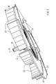
- FIG. 2 shows a side perspective view of a Oven from above, in which the blower chamber 3 by one Housing wall 31 is surrounded by the of the discharge opening 37 side facing substantially cylindrical is designed and towards the blow-out opening 37, for example linear, expanding.
- FIG Intake funnel 32 with the cooling air intake opening 30, the fastening device 60 on the radial fan 2 for the not shown drive motor and the cooling air guide vanes 20 and the base plate 21 of the radial fan located below to see.
- the diversion channel which is actually hidden in FIG.
- 2 5 is through a baffle 58 in two partial flow channels divided by a share of each Mixture K1 + K2 + W from fresh air K1, cooling air K2 and vapors W each a blow-out opening (air passage area) 56th or 57 supplied on or under the control panel 50 and is blown out into the outer space 11 there.
- the diversion channel 5 also widens towards the blow-out openings 56 and 57 in width, so it is in the form of a diffuser.
- a fresh air duct 8 is indicated, whose width varies from one to the width of the Control panel 50 extending air inlet opening 59 to Vapor channel 4 reduced.
- the air inlet opening 59 of the Fresh air duct 8 for transporting fresh air K1 to Radial fan 2 is below the two blow-out openings 56 and 57 arranged.
- the location and number of air intake openings 59 for the fresh air duct 8 can be varied.
- one or more air inlet openings 59 also laterally offset to the blow-out openings, e.g. 56 and 57, of the discharge channel 5, for example in the middle below the deflector 58. This will Air sucked in the middle of the front 12 of the oven and blown out on both sides. This makes possible For example, the targeted cooling of only one in the Middle door handle of a not shown Oven door.
- the fresh air duct 8 is then each in its Shape adapted accordingly to the air inlet openings 59.
- the housing wall 31 of the blower chamber 3 can preferably also be formed spirally in a manner known per se, for example from DE 42 11 755 A1 .
- the housing wall 31 of the blower chamber 3 and the walls of the channels 4, 5 and 8 are preferably formed with sheets, in particular steel sheets.
- FIG. 3 shows the radial fan in a more detailed view 2.
- the cooling air guide vanes 20 and opposite side of the base plate 21, the vapor guide vanes 25 recognizable.
- the cooling air guide vanes 20 and the vapor guide vanes 25 are parallel to the projection Axis of rotation A congruent one above the other and each in the same direction with respect to the radial direction to Axis of rotation A and the shaft 22 curved, in particular all convex or all concave.
- cooling air guide vanes As special A backward curvature of the cooling air guide vanes has been found to be advantageous 20 and the vapor guide vane 25 proved in the case of an imaginary radial line from the axis of rotation A to the outside through a cooling air guide vane 20 or a vapor guide vane 25 extends all radially outer areas of the corresponding cooling air guide vane 20 or vapor guide vane 25 in the direction of rotation are moved forward.
- the cooling air guide vanes 20 and the vapor guide vanes 25 can also be offset from one another in the circumferential direction, so not be congruent with each other. Can also a different number or shape of cooling air guide vanes 20 and vapor guide vanes 25 on the base plate 21 and / or the cooling air guide vanes 20 and / or the vapor guide vanes 25 also in mutually different ones Distances from each other (asymmetrical Arrangement), then on a corresponding The resulting imbalance must be compensated for. Finally, it can also be used to increase the suction effect one, in particular annular, cover the Cooling air guide vanes 20 may be provided upwards, so that the spaces between the cooling air guide vanes 20 down from the base plate 21 and up are completed by the cover.
- the radial fan 2 can in particular consist of a coherent Be formed body, for example a sheet metal body, in which the cooling air guide vanes 20 and the vapor guide vanes 25 on a base plate 21 made of sheet metal a connection technology are applied, or by punching and bending up sheet metal material are formed. Furthermore, the radial fan 2 can also be made of a temperature-resistant Plastic consist, for example, by Injection molded body.
- the ratio R2 is set in particular in a range between approximately 2 and 25 and preferably between approximately 5 and approximately 18.
- the radial blower 2 simultaneously aspirates the smallest possible amount of vapor from the muffle interior 15 and a comparatively large amount of cooling air from the interior of the housing outside the furnace muffle 10.
- the cooling air intake opening 30 is preferably centric arranged to the axis of rotation A, is in the simplest embodiment circular disk-shaped and has one smaller diameter than the radial diameter of the Radial blower 2.
- Regarding the shape of the cooling air guide vanes 20 has a backward curved shape the associated lower noise level proven. However, there are other forms of the cooling air guide vanes 20 possible.
- the height is particularly important the cooling air guide vanes 20, i.e. their dimensions parallel to the axis of rotation A, which is denoted by H in FIG.
- This height H of the cooling air guide vanes 20 is generally between about 4 mm and about 30 mm, especially between about 10 mm and about 20 mm and preferably between about 15 mm and about 20 mm, for example about 17.5 mm.
- the distance between the radial fan 2 and the cooling air intake opening 30 is generally set to a value between about 4 mm and 10 mm and in particular between 5 mm and about 8 mm set depending on the operating speed of the radial fan 2.
- At an operating speed of 1860 RPM (revolutions per minute) has a gap distance proven of about 7 mm.
- the gap distance can be reduced to approx. 5.5 mm, especially with a also reduced speed of 1600 rpm to the to achieve the same cooling air volume flow VK2.
- the vapor guide vanes 25 can in particular like that Cooling air guide vanes 20 can be curved, but can also have a different shape.
- An important parameter is the height of the vapor guide vanes 25, which is denoted by h in FIG is.
- This height h of the vapor guide vane 25 becomes generally chosen between about 1 mm and about 3 mm, in particular about 2 mm, but can also be chosen smaller and in particular only be 0 mm, i.e. that no vapor guide vane 25 are provided and the for suctioning the Wrasen's W required vacuum due to surface friction the base plate 21 of the radial fan 2 is reached.
- the vapor intake opening 36 becomes substantially arranged centrally to the axis of rotation A in order to achieve a uniform To allow suction through the radial fan 2.
- the gap distance is speed-dependent and is generally between about 1 mm and about 4 mm, especially between about 1.5 mm and about 3.5 mm. At a speed of 1600 rpm (without ring cover 1860 rpm) Proven gap distance of 3 mm.
- the vapor guide vanes 25 allow a greater tolerance in the choice of the gap distance, without backing up under the radial fan 2 into the muffle interior 15, a tilting of the ventilation system (Reversal of the flow direction). Thereby the system is less sensitive to manufacturing tolerances.
- the arrangement of the radial fan 2 directly above the vapor outlet opening 18 and the resultant direct vapor extraction can adjust the amount of vapors exactly to the targets become.
- blades can be used as radial fans 2 also be provided with a drum fan radial guide vanes.
- vapor intake opening 36 or blow-out opening 37 instead of only one cooling air intake opening 30, vapor intake opening 36 or blow-out opening 37 also each corresponding Openings may be provided, for example in the form of a Hole pattern.
- FIG 4 shows a development of the embodiment according to FIG 1, in which the fresh air K1 in addition to cooling a Door 9 to close the loading opening 16 of the Furnace muffle 10 is used.
- the door 9 has an upper Area a door handle 91 for handling the door 9 and between a front and a back, which is generally each include a viewing window, a door interior 90 on.
- Air inlet openings 93 In a lower area of the door 9 are Air inlet openings 93, not shown, and in the area of the door handle 91 a further air inlet opening 95 is provided.
- an air outlet opening 94 is directly opposite the air passage opening 55 of the fresh air duct 8 intended.
- both fresh air from the blower 2 K1 passed around the door handle 91 and through the air inlet opening 95 and the air outlet opening 94 in the fresh air duct 8 sucked as well as from below through the air inlet openings 93
- Fresh air K1 through door interior 90 and likewise through the air outlet opening 94 into the fresh air duct 8 of the oven.
- the fresh air K1 therefore cools both the door handle 91 and the door interior 90 and thus also the door front.
- the fresh air duct 8 is in this Design on the door 9 extended towards the front, see above that a multiple flow paths (sub-channels) comprehensive Fresh air duct is created.
- the fresh air duct in the door 9 can be varied in a variety of ways.
- the Exhaust air K1 + K2 + W emerging from the discharge duct 5 becomes led out into the outer frame 11 above the door 9.
Abstract
Description
Die Erfindung betrifft einen Garofen (Back- und Bratofen) und ein Verfahren zum Abführen von Wrasen (Gardünste, Gardämpfe) aus einem von einer Muffelwandung umschlossenen Garraum (Muffelinnenraum) eines Garofens.The invention relates to a cooking oven (baking and roasting oven) and a method for removing vapors (cooking vapors, cooking vapors) from one enclosed by a muffle wall Cooking space (muffle interior) of a cooking oven.
Aus DE 33 46 019 C2 ist ein Garofen bekannt, bei dem die Ofenmuffel sowohl durch elektrische Strahlungsheizkörper (Oberhitze und Unterhitze) als auch durch einen Mikrowellengenerator beheizbar ist. Die Ofenmuffel weist an ihrer Muffeldecke in einem vorderen, der Tür zugewandten Bereich eine Wrasenöffnung auf, in der ein katalytischer Nachbrenner in Form eines porösen Wrasensteins angeordnet ist. Oberhalb der Wrasenöffnung ist ein Lüfterrad mit nach unten zur Wrasenöffnung hin zeigenden Lüfterschaufeln angeordnet, das in einer von einem Lüftergehäuse umschlossenen Saugkammmer angeordnet ist und als Radialgebläse die durch den Wrasenstein hindurchtretende Luft aus dem Muffelinnenraum axial ansaugt und radial durch eine seitliche Auslaßöffnung in dem Lüftergehäuse ausbläst. Das Lüfterrad ist über eine Achse von einem elektrischen Antriebsmotor angetrieben,der nur bei Betrieb des Mikrowellengenerators eingeschaltet wird. Ferner ist unterhalb der Ofentür eine Lufteinlaßöffnung vorgesehen, durch die Luft in den Muffelinnenraum strömen kann. Die Ofenmuffel ist umgeben von Kühlluftkanälen, und im oberen Bereich eines hinter der Ofenmuffel befindlichen senkrechten Kühlluftkanals ist ein Kühlluftgebläse angeordnet, das die erwärmte Luft in der Umgebung der Ofenmuffel ansaugt und durch einen oberhalb der Ofenmuffel horizontal verlaufenden Entlüftungsschacht durch eine Austrittsöffnung oberhalb der Ofentür wieder nach vorne ins Freie ausbläst. In diesen Entlüftungskanal mündet auch die Auslaßöffnung des Wrasensauggebläses, so daß der abgesaugte und vom Katalysator gereinigte Wrasen mit der Kühlluft nach vorne ausgeblasen wird. Durch die innerhalb der Muffel entstehende Luftströmung an der Ofentür entlang wird eine Kondensation von Wrasen an der Innenseite der Ofentür verhindert. Das Wrasensauggebläse saugt ausschließlich Wrasen aus der Ofenmuffel aus dem Muffelinnenraum, nicht jedoch Kühlluft aus der Umgebung der Ofenmuffel an.A cooking oven is known from DE 33 46 019 C2 , in which the oven muffle can be heated both by electric radiant heaters (top heat and bottom heat) and by a microwave generator. On its muffle top, the furnace muffle has a vapor opening in a front area facing the door, in which a catalytic afterburner in the form of a porous vapor stone is arranged. Above the vapor opening there is a fan wheel with fan blades pointing downwards towards the vapor opening, which is arranged in a suction chamber enclosed by a fan housing and, as a radial fan, sucks the air passing through the vapor stone axially out of the muffle interior and blows it out radially through a lateral outlet opening in the fan housing . The fan wheel is driven via an axis by an electric drive motor which is only switched on when the microwave generator is in operation. Furthermore, an air inlet opening is provided below the furnace door, through which air can flow into the interior of the muffle. The furnace muffle is surrounded by cooling air ducts, and in the upper area of a vertical cooling air duct located behind the furnace muffle there is a cooling air blower, which draws in the heated air in the vicinity of the furnace muffle and through a ventilation duct running horizontally above the furnace muffle through an outlet opening above the furnace door blows outside in front. The outlet opening of the vapor suction fan also opens into this ventilation channel, so that the vapor extracted and cleaned by the catalyst is blown out to the front with the cooling air. Condensation of vapors on the inside of the furnace door is prevented by the air flow along the furnace door that arises within the muffle. The vapor suction fan only sucks vapors from the furnace muffle from the interior of the muffle, but not cooling air from the surroundings of the furnace muffle.
DE 35 16 847 C2 offenbart einen Garofen mit einer elektrischen
Konvektionsbeheizung und einer elektrischen Strahlungsbeheizung
in der Ofenmuffel. In der Muffeldecke ist
eine Wrasenabzugsöffnung vorgesehen, in die ein fremdbeheizter
Katalysator eingesetzt ist. Oberhalb der Wrasenabzugsöffnung
ist außerhalb der Ofenmuffel eine Gebläsekammer
angeordnet, in der ein doppelseitig ansaugendes Radialgebläse
untergebracht ist. Das Radialgebläse umfaßt ein Gebläserad
mit einer Trennscheibe, durch die eine Ansaugung
aus den sich gegenüberliegenden Richtungen ermöglicht wird.
Im Betrieb saugt das Radialgebläse von unten Luft aus der
Ofenmuffel über die Wrasenabzugsöffnung und den Katalysator
in die Gebläsekammer und von oben Kühlluft aus dem Geräteinneren
außerhalb der Ofenmuffel an. Die Gebläsekammer
ist nach vorne zur Gerätefront hin mit zwei Strömungskanälen
verbunden, die durch eine Strömungsleitwand in Höhe des
unteren, der Wrasenabzugsöffnung zugewandten Gebläseradteils
voneinander getrennt sind. In den übrigen Bereichen
ist die Gebläsekammer ebenfalls in Höhe des unteren
Gebläseradbereichs in einen oberen und einen unteren Teil
getrennt. Dadurch wird die von oben angesaugte Kühlluft
durch radiales Ausblasen im wesentlichen nur in den oberen
Strömungskanal geleitet und vollständig nach außen vorne
abgeführt, während der von unten abgesaugte Wrasen zu einem
Teil ebenfalls in den oberen Strömungskanal, jedoch zum
überwiegenden Teil in den unteren Strömungskanal eingeleitet
wird und über diesen Strömungskanal als Rückführleitung
wieder durch eine Einlaßöffnung in der Muffeldecke in den
Muffelinnenraum zurückgeleitet wird. Durch diese Rückführung
des gereinigten Abluftanteils wird Energie eingespart.
Nach der Darstellung in der einzigen Figur der DE 35 16 847
C3 handelt es sich bei dem Radialgebläse um einen Trommelläufer.
Aus der DE 38 39 657 C2 ist ein Garofen mit integriertem Mikrowellenteil bekannt. Dieser bekannte Garofen weist an der Muffeldecke eine schachtförmige Wrasenabsaugöffnung auf, oberhalb der ein Wrasenabsauggebläse innerhalb eines Gebläsegehäuses angeordnet ist. Das Wrasenabsauggebläse umfaßt ein von einem Motor angetriebenes Gebläserad mit nach unten zur Wrasenabsaugöffnung hin gerichteten Gebläseschaufeln und mit Öffnungen, durch die sowohl von unten Wrasen aus dem Garraum (Muffelinnenraum) und als auch von oben kühle Umgebungsluft angesaugt wird. Das Gebläsegehäuse weist dazu an einer von der Wrasenabsaugöffnung abgewandten Seite eine Öffnung auf, durch die die kühle Umgebungsluft vom Gebläserad angesaugt werden kann. Im Gebläsegehäuse des Wrasenabsauggebläses wird der durch die Wrasenabsaugöffnung angesaugte Wrasen mit der Umgebungsluft vermischt und durch einen Strömungskanal radial nach vorne zur Gerätefront hin ausgeblasen. In diesen Strömungskanal strömt auch von einem in einem hinteren Ofenbereich angeordneten Kühlluftgebläse über ein Magnetron geführte Kühlluft, die das Kühluftgebläse aus einem Luftkanal im Bereich der Geräterückwand aus einem unteren Bereich des Garofens angesaugt hatte. Ein Teil des von dem Kühlgebläse angesaugten Kühlluftstroms wird über eine mit einer Klappe verschließbare Einlaßöffnung in den Garraum eingeblasen.A cooking oven with an integrated microwave part is known from DE 38 39 657 C2 . This known cooking oven has a shaft-shaped vapor extraction opening on the muffle ceiling, above which a vapor extraction fan is arranged within a fan housing. The vapor extraction fan comprises an impeller driven by a motor with fan blades directed downwards towards the vapor extraction opening and with openings through which vapors are sucked in both from below from the cooking space (muffle interior) and from above, cool ambient air. For this purpose, the fan housing has an opening on a side facing away from the vapor suction opening, through which the cool ambient air can be sucked in by the fan wheel. In the blower housing of the vapor extraction fan, the vapor sucked in through the vapor extraction opening is mixed with the ambient air and blown out through a flow channel radially towards the front of the device. Cooling air also flows into this flow channel from a cooling air blower arranged in a rear oven area via a magnetron, which cooling air blower had sucked in from an air channel in the area of the rear wall of the appliance from a lower area of the cooking oven. Part of the cooling air flow drawn in by the cooling fan is blown into the cooking space via an inlet opening which can be closed by a flap.
DE 42 11 755 A1 offenbart einen weiteren bekannten Garofen mit einer Ofenmuffel, die in der Muffeldecke eine Wrasenabzugsöffnung aufweist, sowie mit einem innerhalb eines Spiralgehäuses angeordneten Radialgebläse, das von unten durch eine Lufteintrittsöffnung aus dem Gehäuseinneren angesaugte Kühlluft radial in einen Diffusorkanal ausbläst, der die Kühlluft nach vorne zu einer Gerätefront hin führt. Die Wrasenabzugsöffnung ist über einen Wrasenschlauch mit einer Einmündungsstelle in dem Diffusorkanal verbunden. Dadurch wird der Wrasen über den Wrasenschlauch und die Wrasenabzugsöffnung durch den vom Radialgebläse erzeugten Kühlluftstrom durch Injektorwirkung aufgrund des dadurch erzeugten dynamischen Unterdrucks abgesaugt und mit der Kühlluft nach vorne ausgeblasen. Das Radialgebläse saugt in dieser Ausführungsform den Wrasen nicht direkt axial an. DE 42 11 755 A1 discloses a further known cooking oven with an oven muffle which has a vapor extraction opening in the muffle ceiling, and with a radial fan arranged inside a spiral housing, which radially blows cooling air drawn in from below through an air inlet opening from the interior of the housing into a diffuser channel, which Cooling air leads to the front of a device. The vapor extraction opening is connected via a vapor hose to a junction in the diffuser channel. As a result, the vapor is sucked off through the vapor hose and the vapor discharge opening by the cooling air flow generated by the radial fan by the action of an injector due to the dynamic vacuum generated thereby and blown out to the front with the cooling air. In this embodiment, the radial fan does not draw the vapors directly axially.
In der DE 43 22 360 A1 ist schließlich ein Einbauherd beschrieben mit einem Garofen unterhalb einer Arbeitsplatte und mit einem in der Arbeitsplatte angeordneten Kochfeld. In dem Kochfeldrahmen ist eine Abluftöffnung vorgesehen, in der ein elektromotorisch angetriebener Sauglüfter angeordnet ist. Im Abstand zu der Abluftöffnung ist ein offenes Ende eines rohrförmigen Wrasenkanals angeordnet. Der Wrasenkanal ist an eine Wrasenauslaßöffnung in der Muffeldecke der Ofenmuffel des Garofens angeschlossen. Der Sauglüfter saugt im Betrieb sowohl Wrasen aus dem Muffelinnenraum als auch seitlich Luft aus dem oberhalb der Garofenmuffel befindlichen Gehäuseinnenbereich des Garofens. Es handelt sich hierbei um einen axialen Sauglüfter, der die Strömung in der gleichen Richtung ausbläst, in der er sie ansaugt. DE 43 22 360 A1 finally describes a built-in cooker with a cooking oven below a worktop and with a hob arranged in the worktop. An exhaust air opening is provided in the cooktop frame, in which an aspirator driven by an electric motor is arranged. An open end of a tubular vapor channel is arranged at a distance from the exhaust air opening. The vapor channel is connected to a vapor outlet opening in the muffle ceiling of the oven muffle of the oven. During operation, the suction fan sucks vapors from the interior of the muffle as well as air from the side of the interior of the oven above the muffle. It is an axial suction fan that blows the flow in the same direction in which it draws it in.
Aus EP 0 330 727 A1 ist ein Einbaugarofen bekannt mit einer von einer Ofentür verschließbaren Garraum einer Ofenmuffel und einem im hinteren Bereich oberhalb der Ofenmuffel angeordneten Kühlluftgebläse. Das Kühlluftgebläse saugt Kühlluft durch eine Öffnung am Boden der Tür aus dem Außenraum an und durch den Türinnenraum sowie durch eine im hinteren Bereich der Tür in der Nähe des Türgriffs angeordnete Luftdurchlaßöffnung in einen horizontal oberhalb der Ofenmuffel verlaufenden Kühlluftansaugkanal, der bis zur Unterdruckseite des Kühlluftgebläses verläuft. An der Überdruckseite des Kühlluftgebläses schließt sich ein Kühlluftausblaskanal an, der oberhalb des Kühlluftansaugkanals auch im wesentlichen horizontal verläuft und durch den das Kühlluftgebläse die Kühlluft oberhalb der Tür wieder an der Frontseite des Garofens in den Außenraum bläst. Ein Abführen von Wrasen aus dem Garraum ist bei diesem bekannten Garofen nicht vorgesehen.From EP 0 330 727 A1 a built-in oven is known Cooking chamber of an oven muffle that can be closed by an oven door and one located in the rear area above the oven muffle Cooling air blower. The cooling air blower sucks cooling air through an opening at the bottom of the door from the outside on and through the door interior and through one in the rear Area of the door in the vicinity of the door handle arranged air passage opening in a horizontally above the oven muffle running cooling air intake duct that extends to the negative pressure side of the cooling air fan runs. On the overprint side of the cooling air blower closes a cooling air discharge duct at the above the cooling air intake duct also essentially runs horizontally and through which the cooling air fan the cooling air above the door again at the front of the Blows the oven into the outside space. A discharge of vapors from the cooking chamber is not provided in this known oven.
Der Erfindung liegt nun die Aufgabe zugrunde, einen besonderen Garofen mit einem Gebläse zum Absaugen von Wrasen aus dem Garraum (Muffelinnenraum) des Garofens und ein besonderes Verfahren zum Abführen von Wrasen aus dem Garraum eines Garofens anzugeben.The invention is based on the object, a special one Cooking oven with a fan for extracting vapors the cooking space (muffle interior) of the oven and a special one Process for removing vapors from the cooking space To specify the oven.
Diese Aufgabe wird gemäß der Erfindung gelöst mit den Merkmalen
des Anspruchs 1 bzw. des Anspruchs 25.This object is achieved according to the invention with the features
of
Der Garofen, insbesondere Einbaugarofen, gemäß Anspruch 1
umfaßt
Das Verfahren nach Anspruch 25 zum Abführen von Wrasen aus
einem von einer Muffelwandung umschlossenen Garraum eines
Garofens, insbesondere eines Einbaugarofens, umfaßt die
Verfahrensschritte:
Die Erfindung beruht auf der Überlegung, den durch die Wrasenaustrittsöffnung in der Muffelwandung abgesaugten Wrasen vor seinem Austritt ins Freie in definierter Menge und Art und Weise mit Frischluft aus dem Freien zu vermischen, um einerseits die Temperatur des Wrasens zu reduzieren und andererseits den Wrasen zu verdünnen, so daß Ablagerungen und Verschmutzungen verringert werden. Die Frischluft wird gezielt durch wenigstens einen Frischluftkanal zum Ansaugbereich (Unterdruckseite) des Gebläses geführt. Durch die Abmessungen des Frischluftkanals kann die pro Zeiteinheit zugeführte Frischluftmenge (der Volumenstrom der Frischluft) bei jeweils vorgegebener Saugleistung des Gebläses auf die gewünschte Größe eingestellt werden. Auch das Verhältnis der Volumenströme von Frischluft und Wrasen zueinander kann durch die Dimensionierung und Anordnung des Frischluftkanals im Verhältnis zu der Dimensionierung und Anordnung der Wrasenaustrittsöffnung genau eingestellt werden.The invention is based on the consideration given by the vapor outlet opening Vapors extracted in the muffle wall before leaving the market in a defined quantity and type and way to mix with fresh air from the outdoors to reduce the temperature of the vapor on the one hand and on the other hand to dilute the vapors so that deposits and Soiling can be reduced. The fresh air is targeted through at least one fresh air duct to the intake area (Vacuum side) of the blower. By the dimensions of the fresh air duct can be supplied per unit of time Fresh air volume (the volume flow of fresh air) at the given suction power of the blower to the desired size can be set. The relationship too the volume flows of fresh air and vapors to each other can through the dimensioning and arrangement of the fresh air duct in relation to the dimensioning and arrangement of the Vapor outlet opening can be set precisely.
Vorteilhafte Weiterbildungen und Ausgestaltungen des Garofens
und des Verfahrens ergeben sich aus den vom Anspruch 1
bzw. Anspruch 25 jeweils abhängigen Ansprüchen.Advantageous further developments and refinements of the cooking oven
and the method result from that of
Der Garofen weist im allgemeinen eine Frontseite auf, an der eine Beschickungsöffnung der Ofenmuffel zum Beschicken des Garraums mit Gargut die Beschickungsöffnung und eine Ofentür zum Verschließen dieser Beschickungsöffnung angeordnet sind. Es münden nun in einer vorteilhaften Ausführungsform entweder der Frischluftkanal oder der Ausleitkanal oder vorzugsweise auch beide an der Frontseite des Garofens in den Außenraum. Insbesondere bei einem Einbaugarofen können dadurch relativ große Volumenströme (Gasvolumen pro Zeiteinheit, Gasfluß) des Frischluft- und/oder des Abluftstromes erreicht werden. Der Frischluftkanal und/oder der Abluftkanal können bzw. kann allerdings auch an einer anderen Stelle ins Freie münden, insbesondere an der von der Frontseite abgewandten hinteren Seite (Rückseite) des Garofens. In einer besonderen Kombination kann die Frischluft von vorne angesaugt und die Ablauft nach hinten, vorzugsweise nach hinten oben, beispielsweise zu einer Dunstabzugseinrichtung mit nachfolgendem Kamin hin, ausgeblasen werden.The oven generally has a front the one loading opening of the furnace muffle for loading the loading opening and a Furnace door arranged to close this loading opening are. It now opens in an advantageous embodiment either the fresh air duct or the discharge duct or preferably both on the front of the oven in the outside space. Especially with a built-in oven relatively large volume flows (gas volume per unit of time, gas flow) of the fresh air and / or the exhaust air flow can be achieved. The fresh air duct and / or however, the exhaust air duct can also be connected to one lead to another place, especially at the the rear side (rear side) of the Oven. In a special combination, the fresh air sucked in from the front and the drain to the rear, preferably towards the top, for example to an extractor hood with subsequent chimney, blown out become.
Der Frischluftkanal und der Ausleitkanal verlaufen in einer bevorzugten Ausführungsform zumindest überwiegend oberhalb der Ofenmuffel, vorzugsweise im wesentlichen horizontal, wobei der Ausleitkanal vorzugsweise oberhalb des Frischluftkanals verläuft. Dadurch kann der besonders stark wärmebelastete Bereich über der Muffeldecke mit der noch kühlen Frischluft gekühlt werden bei zugleich kompaktem Aufbau. Ein besonders kompakter Aufbau wird erreicht, wenn der Frischluftkanal und der Ausleitkanal durch einen gemeinsamen, vorzugsweise plattenförmig ausgebildeten, Luftleitkörper (Luftleitplatte, Trennwand) voneinander getrennt sind, so daß eine zweite Kanalwand entfallen kann.The fresh air duct and the discharge duct run in one preferred embodiment at least predominantly above the oven muffle, preferably essentially horizontal, the discharge duct preferably above the fresh air duct runs. As a result, the particularly heavily heat-loaded Area above the muffle ceiling with the still cool Fresh air is cooled with a compact design. A particularly compact structure is achieved if the Fresh air duct and the discharge duct through a common, preferably plate-shaped, air guide (Air baffle, partition) are separated from each other, so that a second channel wall can be omitted.
Die Mündungsbereiche von Frischluftkanal und Ausleitkanal in den Außenraum können zumindest teilweise innerhalb eines gemeinsamen Mündungsbereiches liegen oder auch voneinander getrennt sein und zueinander versetzt, insbesondere an der Frontseite seitlich zueinander versetzt, angeordnet sein.The mouth areas of the fresh air duct and discharge duct in the outside space can at least partially within one common mouth area or from each other be separated and offset from each other, especially on the Front side offset from one another, be arranged.
Der Frischluftstrom kann nun zusätzlich zum Kühlen von Teilen der Garofentür verwendet werden, insbesondere des Türgriffes und/oder des Türinnenraumes, um die Temperaturen an der Tür zu vermindern. Dazu wird der Frischluftstrom durch entsprechende Ausbildung des Frischluftkanals mit diesen Teilen in Kontakt gebracht. Ebenso kann der Frischluftstrom auch zum Kühlen einer im allgemeinen an der Frontseite vorgesehenen Bedienblende und der dort angeordneten Bedienelemente des Garofens verwendet werden.The fresh air flow can now also be used to cool parts the oven door can be used, especially the door handle and / or the door interior to the temperatures diminish the door. For this, the fresh air flow is through appropriate training of the fresh air duct with these Brought into contact. The fresh air flow can also also for cooling one generally provided on the front Control panel and the controls arranged there of the oven.
Das Gebläse ist vorzugsweise in einer Gebläsekammer zum Führen der Strömung angeordnet. Die Gebläsekammerwandung weist wenigstens eine im Ansaugbereich des Gebläses angeordnete und mit der Wrasenaustrittsöffnung in der Muffelwandung über einen Wrasenkanal verbundene Wrasenansaugöffnung und wenigstens eine im Ausblasbereich des Gebläses angeordnete und an den Ausleitkanal angeschlossene Ausblasöffnung auf. Der Frischluftkanal mündet in den Wrasenkanal, so daß die Frischluft vor dem Gebläse dem Wrasen beigemischt wird. Der Wrasenkanal ist insbesondere durch eine um die Ofenmuffelwandung befindliche thermische Muffelisolierung geführt.The blower is preferably in a blower chamber for Leading the flow arranged. The blower chamber wall has at least one arranged in the suction area of the blower and with the vapor outlet opening in the muffle wall vapor intake opening connected via a vapor channel and at least one in the blow-out area of the blower arranged and connected to the discharge duct discharge opening on. The fresh air duct opens into the vapor duct, so that the fresh air is mixed with the vapor in front of the fan becomes. The fume channel is in particular through a the thermal muffle insulation located on the furnace muffle wall guided.
Die Wandung der Wrasenkanals und wenigstens ein Teil der Wandung des Frischluftkanals können zur Montageerleichterung zusammenhängend, insbesondere aus einem gemeinsamen Blechteil, ausgebildet sein.The wall of the vapor channel and at least part of the Wall of the fresh air duct can make installation easier coherent, especially from a common one Sheet metal part, be formed.
Die Wrasenansaugöffnung in der Wandung der Gebläsekammer hat vorzugsweise einen größeren Strömungsquerschnitt als die Wrasenaustrittsöffnung in der Muffelwandung, und der Wrasenkanal nimmt dann in seinem Strömungsquerschnitt von der Wrasenaustrittsöffnung zur Wrasenansaugöffnung hin, vorzugsweise im wesentlichen kontinuierlich, zu (nach Art eines Diffusors). Man kann dadurch ein Gebläse mit einem größeren effektiven Saugquerschnitt und damit einer größeren Leistung auch ohne Erhöhung von dessen Drehzahl verwenden. Dadurch kann der Ansaugunterdruck für den Wrasen aus dem Garraum ohne Veränderung der Wrasenaustrittsöffnung oder Verkürzung des Wrasenkanals erhöht werden.The vapor intake opening in the wall of the blower chamber preferably has a larger flow cross section than the vapor outlet opening in the muffle wall, and the Vapor channel then decreases in its flow cross section the vapor outlet opening towards the vapor suction opening, preferably essentially continuous, too (according to Art a diffuser). You can use a blower with a larger effective suction cross-section and thus a larger one Use power even without increasing its speed. This can remove the suction vacuum for the vapors the cooking space without changing the vapor outlet opening or shortening the vapor channel can be increased.
In einer vorteilhaften Weiterbildung weist die Wandung der Gebläsekammer zusätzlich wenigstens eine Kühlluftansaugöffnung auf, über die die Gebläsekammer mit der Umgebung der Ofenmuffel innerhalb eines Ofengehäuses in Strömungsverbindung steht. Das Gebläse saugt dann nicht nur Wrasen aus dem Garraum und Frischluft an, sondern auch die von der Ofenmuffel erwärmte Luft im Garofengehäuse, und dient dadurch auch als Kühlgebläse.In an advantageous development, the wall of the Blower chamber additionally at least one cooling air intake opening on through which the blower chamber with the environment the furnace muffle in flow communication within an furnace housing stands. The fan then not only sucks vapors from the cooking space and fresh air, but also from the Oven muffle warms air in the oven housing, and thereby serves also as a cooling fan.
Vorzugsweise ist das Gebläse ein Radialgebläse mit einer Drehachse und mit wenigstens einem in einer im wesentlichen parallel zur Drehachse verlaufenden Ansaugrichtung liegenden axialen Ansaugbereich sowie wenigstens einem im wesentlichen in Umfangsrichtung zur Drehachse verlaufenden radialen Ausblasbereich.The blower is preferably a radial blower with a Axis of rotation and with at least one in one essentially parallel to the axis of rotation of the suction direction axial suction area and at least one essentially radial radial to the axis of rotation Blow-out area.
Das Radialgebläse kann zwei auf entgegengesetzten Seiten einer Trennebene liegende Ansaugbereiche aufweisen (doppelflutige Ausführung). Die wenigstens eine Wrasenansaugöffnung der Gebläsekammer wird dann in einem der Ansaugbereiche und die Kühlluftansaugöffnung der Gebläsekammer in dem anderen der beiden Ansaugbereiche des Radialgebläses angeordnet. Die Wrasenansaugöffnung der Gebläsekammer kann insbesondere im wesentlichen symmetrisch zur Drehachse des Radialgebläses angeordnet sein.The radial fan can have two on opposite sides have suction areas lying on a parting plane (double-flow Execution). The at least one vapor intake opening the blower chamber is then in one of the suction areas and the cooling air intake opening of the blower chamber in the other of the two suction areas of the radial fan. The vapor intake opening of the blower chamber can in particular essentially symmetrical to the axis of rotation of the radial fan be arranged.
Das Radialgebläse kann ein Trommelläufer sein. Vorzugsweise ist als Radialgebläse ein um die Drehachse drehbares Schaufelrad vorgesehen, das vorzugsweise die Wrasenansaugöffnung von der Drehachse nach außen in allen Richtungen überragt. In dieser Ausführung kann das Schaufelrad (Radialgebläse) im der Wrasenansaugöffnung zugeordneten Ansaugbereich Wrasenleitschaufeln aufweisen. Dies ermöglicht eine genaue Einstellung des angesaugten Volumenstromes aus Wrasen und Frischluft durch die Wahl der Anzahl, der Gestalt und der Größe der Wrasenleitschaufel. Das Schaufelrad des Radialgebläses kann aber auch an der der Wrasenabsaugöffnung zugewandten Seite Gas/Luft lediglich aufgrund einer Flächenreibung an der Grundplatte fördern. The radial fan can be a drum rotor. Preferably as a radial fan is a paddle wheel that can be rotated around the axis of rotation provided that preferably the vapor intake opening towered outwards in all directions from the axis of rotation. In this version, the paddle wheel (radial fan) Vapor guide vanes in the suction area assigned to the vapor intake opening exhibit. This enables an accurate Adjustment of the intake volume flow from vapors and Fresh air by choosing the number, the shape and the Vapor guide vane size. The impeller of the radial fan but can also on the vapor extraction opening facing Gas / air side only due to surface friction convey on the base plate.
Das Schaufelrad des Radialgebläses weist vorzugsweise ferner in der Trennebene eine Trennplatte und an dem der Kühlluftansaugöffnung zugeordneten Ansaugbereich mit der Trennplatte verbundene und, vorzugsweise im wesentlichen senkrecht zur Trennplatte gerichtete, Kühlluftleitschaufeln auf, durch die der Kühlluft-Volumenstrom eingestellt werden kann, insbesondere im Verhältnis zum Volumenstrom des Frischluft/Wrasen-Gemischs.The impeller of the radial fan preferably also has in the parting plane a partition plate and on that of the cooling air intake assigned suction area with the partition plate connected and, preferably substantially perpendicular cooling air guide vanes directed towards the separating plate through which the cooling air volume flow can be set can, especially in relation to the volume flow of the Fresh air / vapor mixture.
Die Wrasenaustrittsöffnung ist im allgemeinen in der Muffeldecke angeordnet, um zusätzlich die thermischen Auftriebskräfte zu nutzen.The vapor outlet opening is generally in the muffle ceiling arranged to additionally lift the thermal forces to use.
Die Gebläsekammer mit dem Gebläse ist in einer bevorzugten Ausführungsform oberhalb der Muffeldecke der Ofenmuffel angeordnet, vorzugsweise oberhalb der Wrasenaustrittsöffnung. Der Wrasenkanal verläuft dann im wesentlichen senkrecht nach oben (entgegen der Schwerkraft). Die Gebläsekammer kann natürlich auch an einer anderen Stelle der Ofenmuffel, insbesondere an deren Rückwand, angeordnet sein.The blower chamber with the blower is in a preferred one Embodiment arranged above the muffle ceiling of the oven muffle, preferably above the vapor outlet opening. The vapor channel then runs essentially vertically upwards (against gravity). The blower chamber Of course, the muffle can also be in particular on its rear wall.
Zur weiteren Erläuterung der Erfindung wird auf die Zeichnungen Bezug genommen, in denen Ausführungsbeispiele gemäß der Erfindung jeweils schematisch dargestellt sind. Es zeigen:
- FIG 1
- einen oberen Bereich eines Garofens in einem seitlichen Schnitt,
- FIG 2
- einen inneren oberen Bereich eines Garofens in einer Ansicht von seitlich oben
- FIG 3
- ein Lüfterrad für einen Garofen in einer Ansicht und
- FIG 4
- einen oberen Bereich eines Garofens gemäß FIG 1 mit einer durch die Frischluft gekühlten Tür in einem seitlichen Schnitt,.
- FIG. 1
- an upper area of a cooking oven in a lateral section,
- FIG 2
- an inner upper region of a cooking oven in a side view from above
- FIG 3
- a fan wheel for a cooking oven in one view and
- FIG 4
- an upper area of a cooking oven according to FIG 1 with a door cooled by the fresh air in a lateral section.
Einander entsprechende Teile sind in den FIG 1 bis 4 mit denselben Bezugszeichen versehen.Corresponding parts are shown in FIGS. 1 to 4 provided the same reference numerals.
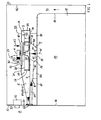
In FIG 1 ist ein Garofen in einem seitlichen Schnitt dargestellt
mit einer Ofenmuffel 10 mit einer von einer Muffelwandung
(nur Muffeldecke 17 und Muffelrückwand 14 dargestellt)
umgebenen Muffelinnenraum (Garraum) 15, einer an
einer Frontseite 12 angeordneten Beschickungsöffnung 16 in
der Muffelwandung, durch die Gargut in den Muffelinnenraum
15 einbringbar ist, und einem Gehäuse 83.1 shows a cooking oven in a lateral section
with an
Oberhalb der Muffeldecke 17 der Ofenmuffel 10 ist eine Gebläsekammer
3 mit einem Radialgebläse 2 angeordnet. Das Radialgebläse
2 weist einen entlang einer Drehachse A bevorzugt
ausgedehnten (länglichen) Schaft 22 und eine an diesem
Schaft 22 befestigte, vorzugsweise symmetrisch zur Drehachse
A ausgebildete Grundplatte (Trägerplatte, Trennplatte)
21 auf. Die Grundplatte 21 ist in einem unmittelbar an den
Schaft 22 anschließenden inneren Bereich domförmig (trichterförmig)
eingebuchtet und in den außen anschließenden Bereich
im wesentlichen flach ausgebildet. In dem flachen
ringförmigen Bereich der Grundplatte 21 sind mehrere Kühlluftleitschaufeln
20 vorgesehen, die an der Grundplatte 21
befestigt oder aus dieser ausgeformt sind sowie im wesentlichen
senkrecht von der Grundplatte 21 nach oben zu einer
Kühlluftansaugöffnung 30 in der Gehäusewandung 31 der Gebläsekammer
3 abstehen. Die Kühlluftansaugöffnung 30 ist an
der von der Ofenmuffel 10 abgewandten Gehäusedecke 33 der
Gehäusewandung 31 der Gebläsekammer 3 vorgesehen und kann
insbesondere am Fuß eines mit der Gehäusewandung gebildeten
Ansaugtrichters 32 angeordnet sein. In einem der Ofenmuffel
10 zugewandten Gehäuseboden 34 der Gehäusewandung 31 ist
wenigstens eine Wrasenansaugöffnung 36 ausgebildet. Diese
Wrasenansaugöffnung 36 ist über einen Wrasenkanal 4 mit einer
Wrasenaustrittsöffnung 18 in der Muffeldecke 17 der
Ofenmuffel 10 verbunden. Vorzugsweise sind die Kühlluftansaugöffnung
30, die Wrasenansaugöffnung 36 und die Wrasenaustrittsöffnung
18 jeweils im wesentlichen zentrisch zur
Drehachse A sowie vorzugsweise auch rotationssymmetrisch
zur Drehachse A ausgebildet. Das Radialgebläse 2 weist an
seiner Grundplatte 21 zur Wrasenansaugöffnung 36 hin weitere
Lüfterradschaufeln auf, die als Wrasenleitschaufeln 25
bezeichnet sind.Above the
Außer der Kühlluftansaugöffnung 30 und der Wrasenansaugöffnung
36 weist die Wandung 31 der Gebläsekammer 3 eine weitere
Öffnung auf, die nicht axial zur Drehachse A, sondern
senkrecht dazu in radialer Richtung zur Gerätefront des Garofens
hin gerichtet ist und als Ausblasöffnung 37 bezeichnet
ist. Ansonsten ist die Wandung 31 der Gebläsekammer 3,
insbesondere deren Seitenwandung 35 in Umfangsrichtung bezüglich
der Drehachse A um das Radialgebläse 2 herum, geschlossen.
Über eine mit dem Schaft 22 des Radialgebläses 2
verbundene Halteeinrichtung 60 ist ein elektrischer Antriebsmotor
6 zum Drehen des Radialgebläses 2 um seine
Drehachse A befestigt.Except for the cooling
Zwischen dem Gehäuseboden 34 der Gebläsekammer 3 und der
Muffeldecke 17 ist eine nur teilweise dargestellte Muffelisolierung
84 vorgesehen, durch die der Wrasenkanal 4
geführt ist, wobei die Muffelisolierung 84 an der Kanalwandung
40 des Wrasenkanals 4 anliegt. Der Wrasenkanal 4 hat
eine von der Wrasenaustrittsöffnung 18 in der Muffeldecke
17 zur Wrasenansaugöffnung 36 im Gehäuseboden 34 zunehmenden
Querschnitt, ist also trichterförmig oder in Form eines
Diffusors gebildet. Die Kanalwandung 40 und der Gehäuseboden
34 können insbesondere mit einem gemeinsamen Blechteil
gebildet sein, so daß der trichterförmige Wrasenkanal 4
Teil des Gehäuses der Gebläsekammer 3 ist. Ferner ist innerhalb
des Wrasenkanals 4 ein nach oben von der Wrasenaustrittsöffnung
18 verlaufender Wrasenstutzen 41 ausgebildet,
um den ein rinnenförmiger Kondensatsammelbereich 42 gebildet
ist. Dies hat den Vorteil, daß an den kälteren Bereichen
der Kanalwandung 40 kondensierende Wrasenkondensat
sich in dem Kondensatsammelbereich 42 sammeln kann und
nicht in den Muffelinnenraum 15 und auf das darin befindliche
Gargut tropfen kann.Between the
Von der Frontseite 12 des Garofens verläuft ein Frischluftkanal
8 bis in den Wrasenkanal 4. Der Frischluftkanal 8
mündet in einem Luftdurchlaßbereich 55 an der Frontseite 12
und mit seinem anderen Ende an einer der Frontseite 12 zugewandten
Seite des Wrasenkanals 4 und verläuft im wesentlichen
horizontal sowie parallel zur Muffeldecke 17. Nach
oben ist der Frischluftkanal 8 durch eine Luftleitwand 7
und nach unten durch einen Luftleitboden 80 begrenzt und
gasdicht abgeschlossen.A fresh air duct runs from the
Zum Betreiben des Radialgebläses 2 wird der Antriebsmotor 6
eingeschaltet, und das Radialgebläse 2 beginnt sich um die
Drehachse A mit einer vom Antriebsmotor 6 vorgegebenen
Drehrichtung und Drehzahl zu drehen. Durch die Drehbewegung
wird von den Kühlluftleitschaufeln 20 mit K2 bezeichnete
Kühlluft axial, d.h. im wesentlichen parallel zur Drehachse
A, angesaugt und radial, d.h. senkrecht zur Drehachse A
nach außen, ausgeblasen. Da die Gebläsekammer 3 nur an der
Ausblasöffnung 37 radial nach außen offen ist und im übrigen
von der Seitenwandung 35 abgeschlossen ist, wird die
angesaugte Kühlluft K2 vollständig durch die Ausblasöffnung
37 aus der Gebläsekammer 3 ausgeleitet. Durch die Drehung
des Radialgebläses 2 werden aber auch mit Hilfe der an der
Unterseite der Grundplatte 21 vorgesehenen Wrasenleitschaufeln
25 mit W bezeichneter Wrasen (Luft aus dem Muffelinnenraum,
die im Garbetrieb mit Gar- und Fettdämpfen angereichert
ist) aus dem Muffelinnenraum 15 und mit K1 bezeichnete
Frischluft aus dem Außenraum 11 außerhalb des
Ofengehäuses 83 axial angesaugt. Der angesaugte Wrasen W
strömt nacheinander durch die Wrasenaustrittsöffnung 18,
den Wrasenkanal 4 und die Wrasenansaugöffnung 36, die angesuagte
Frischluft K1 nacheinander durch den Frischluftkanal
8 und die Wrasenansaugöffnung 36. Auch das Gemisch aus Wrasen
W und Frischluft K1 wird vom Radialgebläse 2 radial
nach außen geleitet und vollständig durch die Ausblasöffnung
37 aus der Gebläsekammer 3 ausgeblasen.To operate the
An die Ausblasöffnung 37 der Gebläsekammer 3 ist ein Ausleitkanal
(Abluftkanal) 5 angeschlossen, über den sowohl
die Kühlluft K2 als auch der Wrasen W (mit der Frischluft
K1) als Gasgemisch K1+K2+W bis zu dem Luftdurchlaßbereich
55 an der Frontseite 12 des Garofens geführt wird und dort
in den Außenraum 11 ausgeleitet wird. An der Frontseite 12
des Garofens ist oberhalb des Luftdurchlaßbereichs 55 eine
Bedienblende 50 mit einem oder mehreren Bedienelementen 51
und mit hinter der Bedienblende 50 angeordneten und mit den
Bedienelementen 51 verbundenen Steuerelementen 52, die insbesondere
elektronische Bauteile enthalten können, angeordnet.At the blow-out
Die Frischluft K1 hat zum einen die Funktion, den Wrasen W
zu verdünnen und damit eine Verschmutzung der Frontseite 12
des Garofens oder von im Luftstrom im aus der Luftdurchlaßöffnung
55 austretenden Luftstrom befindlichen Gegenständen
zu verringern, und zum anderen auch eine Kühlfunktion für
den vorderen Bereich des Garofens um den Frischluftkanal 8
sowie auch den Bereich um den Ausleitkanal 5, da mit der
kühlen Frischluft K1 auch das Gemisch K1+K2+W in seiner
Temperatur vermindert wird. Das Verhältnis R1 = VK1/VW des
Volumenstroms VK1 der Frischluft K1 zum Volumenstrom VW des
Wrasens W wird durch die Bemessungen des Frischluftkanals 8
und des Wrasenkanals 4 mit den zugehörigen Einlaßöffnungen
55 bzw. 18 bestimmt und kann in einem weiten Bereich variiert
werden.On the one hand, the fresh air K1 has the function of the vapor W
to dilute and thus contaminate the
Das Verhältnis R1 der Volumenströme von Frischluft K1 und Wrasen W liegt vorzugsweise in einem Bereich zwischen 1 und 5 (1 ≤ R1 ≤ 5).The ratio R1 of the volume flows of fresh air K1 and Wrasen W is preferably in a range between 1 and 5 (1 ≤ R1 ≤ 5).
Absolut werden die Volumenströme VK1 und VW wie folgt gewählt: Der Volumenstrom des Wrasens W liegt im allgemeinen zwischen 2 m3/h und 10 m3/h und der Volumenstrom VK1 der Frischluft K1 zwischen 2 m3/h und 50 m3/h.In absolute terms, the volume flows VK1 and VW are selected as follows: The volume flow of the vapor W is generally between 2 m 3 / h and 10 m 3 / h and the volume flow VK1 of the fresh air K1 is between 2 m 3 / h and 50 m 3 / h .
Die Kühlluft K2 kann in der dargestellten Ausführungsform
aus dem gesamten die Ofenmuffel 10 umgebenden Innenraum des
Gehäuses 83 angesaugt werden, insbesondere aus dem oberen
Bereich hinter der Bedienblende 50, in dem die Steuerelemente
52 angeordnet sind, zu deren Kühlung sowie auch aus
einem hinter der Muffelrückwand 14 und vor der Rückwand des
Gehäuses 83 befindlichen Strömungskanals 74 von unten. Dadurch
wird auch die Umgebung der Ofenmuffel 10 gekühlt. Der
Bereich, aus dem die Kühlluft K2 angesaugt wird, kann aber
auch durch Strömungsleitkörper oder zusätzliche Strömungskanäle
begrenzt oder gezielt ausgewählt werden, wenn man
nur einen Teilbereich des Garofens kühlen will, beispielsweise
aus Energiespargründen. Dieser Teilbereich kann insbesondere
ein vorderer Bereich des Garofens sein, der insbesondere
eine Tür zum Verschließen der Beschickungsöffnung
16 und vorzugsweise noch den Bereich der Bedienblende 50
mit den temperaturempfindlichen elektronischen Bauelemente
in den Steuerelementen 52 umfaßt. The cooling air K2 can in the illustrated embodiment
from the entire interior of the furnace muffle 10
In einer nicht dargestellten Ausführungsform kann aber auch
die Kühlluftansaugöffnung 30 in der Gebläsekammer 3 entfallen.
Das Gebläse 2 dient dann nicht mehr zum Kühlen der
weiteren Bereiche des Garofens, sonder nur noch des Bereiches
um den Frischluftkanal 8 und auch den Ausleitkanal 5.In an embodiment not shown, however, can also
the cooling
FIG 2 zeigt eine seitliche perspektivische Ansicht eines
Garofens von oben, bei dem die Gebläsekammer 3 von einer
Gehäusewandung 31 umgeben ist, die an der von der Ausblasöffnung
37 abgewandten Seite im wesentlichen zylinderförmig
gestaltet ist und sich zur Ausblasöffnung 37 hin, beispielsweise
linear, aufweitet. Es sind in FIG 2 ferner der
Ansaugtrichter 32 mit der Kühlluftansaugöffnung 30, die Befestigungsvorrichtung
60 am Radialgebläse 2 für den nicht
dargestellten Antriebsmotor und die Kühlluftleitschaufeln
20 sowie die Grundplatte 21 des darunter befindlichen Radialgebläses
zu sehen. Der an sich in FIG 2 verdeckte Ausleitkanal
5 ist durch einen Ablenkkörper 58 in zwei Teilströmungskanäle
geteilt, durch die jeweils ein Anteil des
Gemisches K1+K2+W aus Frischluft K1, Kühlluft K2 und Wrasen
W jeweils einer Ausblasöffnung (Luftdurchlaßbereich) 56
bzw. 57 an oder unter der Bedienblende 50 zugeführt und
dort in den Außenraum 11 ausgeblasen wird. Der Ausleitkanal
5 weitet sich ferner zu den Ausblasöffnungen 56 und 57 hin
in seiner Breite auf, ist also in Form eines Diffusors ausgebildet.
Unterhalb einer den Boden des Ausleitkanals 5
bildenden Luftleitwand 7 ist ein Frischluftkanal 8 angedeutet,
dessen Breite sich von einer sich über die Breite der
Bedienblende 50 erstreckenden Lufteinlaßöffnung 59 bis zum
Wrasenkanal 4 hin verringert. Die Lufteinlaßöffnung 59 des
Frischluftkanals 8 zum Transportieren von Frischluft K1 zum
Radialgebläse 2 ist unterhalb der beiden Ausblasöffnungen
56 und 57 angeordnet. Die Lage und Zahl der Lufteinlaßöffnungen
59 für den Frischluftkanal 8 kann variiert werden.
Insbesondere können eine oder mehrere Lufteinlaßöffnungen
59 auch seitlich versetzt zu den Ausblasöffnungen, z.B. 56
und 57, des Ausleitkanals 5 angeordnet sein, beispielsweise
in der Mitte unterhalb des Ablenkkörpers 58. Dadurch wird
Luft in der Mitte der Frontseite 12 des Garofens angesaugt
und an den beiden Seiten jeweils ausgeblasen. Dies ermöglicht
beispielsweise die gezielte Kühlung eines nur in der
Mitte angeordneten Türgriffs einer nicht dargestellten
Ofentür. Der Frischluftkanal 8 wird dann jeweils in seiner
Gestalt entsprechend an die Lufteinlaßöffnungen 59 angepaßt.2 shows a side perspective view of a
Oven from above, in which the
In Abweichung von den dargestellten Ausführungsformen kann
die Gehäusewandung 31 der Gebläsekammer 3 vorzugsweise auch
spiralförmig ausgebildet sein in an sich, beispielsweise
aus der DE 42 11 755 A1, bekannter Weise. Die Gehäusewandung
31 der Gebläsekammer 3 und die Wandungen der Kanäle 4,
5 und 8 sind vorzugsweise mit Blechen, insbesondere Stahlblechen,
gebildet.In a departure from the illustrated embodiments, the
FIG 3 zeigt in einer detaillierteren Ansicht das Radialgebläse
2. Es sind die Kühlluftleitschaufeln 20 und an der
gegenüberliegenden Seite der Grundplatte 21 die Wrasenleitschaufeln
25 zu erkennen. Die Kühlluftleitschaufeln 20 und
die Wrasenleitschaufeln 25 sind in Projektion parallel zur
Drehachse A deckungsgleich übereinander und jeweils in der
gleichen Richtung bezogen auf die radiale Richtung zur
Drehachse A und dem Schaft 22 gekrümmt, insbesondere alle
konvex gekrümmt oder alle konkav gekrümmt. Als besonders
vorteilhaft hat sich eine Rückwärtskrümmung der Kühlluftleitschaufeln
20 und der Wrasenleitschaufel 25 erwiesen,
bei der bei einer gedachten radialen Linie von der Drehachse
A nach außen, die durch eine Kühlluftleitschaufel 20
oder eine Wrasenleitschaufel 25 verläuft, alle radial weiter
außen liegenden Bereiche der entsprechenden Kühlluftleitschaufel
20 bzw. Wrasenleitschaufel 25 in Drehrichtung
nach vorne versetzt sind.3 shows the radial fan in a more
Die Kühlluftleitschaufeln 20 und die Wrasenleitschaufeln 25
können auch in Umfangsrichtung zueinander versetzt sein,
also nicht deckungsgleich zueinander sein. Ferner können
eine unterschiedliche Anzahl oder Form von Kühlluftleitschaufeln
20 und Wrasenleitschaufeln 25 an der Grundplatte
21 vorgesehen sein und/oder die Kühlluftleitschaufeln 20
und/oder die Wrasenleitschaufeln 25 auch in voneinander unterschiedlichen
Abständen zueinander angeordnet sein (asymmetrische
Anordnung), wobei dann auf ein entsprechendes
Ausgleichen der dadurch entstehenden Unwucht zu achten ist.
Schließlich kann auch zur Vergrößerung der Saugwirkung zusätzlich
eine, insbesondere ringförmige, Abdeckung der
Kühlluftleitschaufeln 20 nach oben vorgesehen sein, so daß
die zwischen den Kühlluftleitschaufeln 20 liegenden Zwischenräume
nach unten von der Grundplatte 21 und nach oben
durch die Abdeckung abgeschlossen sind.The cooling
Das Radialgebläse 2 kann insbesondere aus einem zusammenhängenden
Körper gebildet sein, beispielsweise einem Blechkörper,
bei dem die Kühlluftleitschaufeln 20 und die Wrasenleitschaufeln
25 auf eine Grundplatte 21 aus Blech durch
eine Verbindungstechnik aufgebracht sind, oder durch Ausstanzen
und Hochbiegen von Blechmaterial gebildet sind.
Ferner kann das Radialgebläse 2 auch aus einem temperaturbeständigen
Kunststoff bestehen, beispielsweise einem durch
Spritzguß hergestellten Formkörper.The
In allen Ausführungsformen wird nun vorzugsweise durch auf
die ausgewählte Drehzahl des Radialgebläses 2 abgestimmte
konstruktive Maßnahmen erreicht, daß der Volumenstrom, der
angesaugten Kühlluft K2 um mindestens das sechsfache größer
ist als der Volumenstrom des Wrasens W und der Frischluft
K1. Es hat sich gezeigt, daß bei einer solchen Einstellung
des Verhältnisses R2=VK2/VW+VK1) von Kühlluftvolumenstrom
VK2 zur Summe VK1+VW aus Frischluftvolumenstrom VK1 und
Wrasenvolumenstrom VW auch bei einer nicht zu großen Absaugwirkung
für den Wrasen W aus dem Muffelinnenraum 15
dennoch eine ausreichende Kühlung des Garofens erreicht
wird. Das Verhältnis R2 wird insbesondere in einem Bereich
zwischen etwa 2 und 25 und vorzugsweise zwischen etwa 5 und
etwa 18 eingestellt. Für die Kühlung eines Einbaugarofens
mit den üblichen standardisierten Maßen hat sich ein Volumenstrom
der Kühlluft K2 von über 100 m3/h, insbesondere
zwischen 120 m3/h und 200 m3/h, vorzugsweise bei etwa 150
m3/h als zweckmäßig erwiesen. Für den Volumenstrom des Wrasens
sind dagegen Werte zwischen 2 m3/h und 10 m3/h, insbesondere
bei etwa 6 m3/h zweckmäßig. Es wird also vom Radialgebläse
2 gleichzeitig eine möglichst eng definierte Wrasenmenge
aus dem Muffelinnenraum 15 und eine vergleichsweise
große Kühlluftmenge aus dem Gehäuseinneren außerhalb der
Ofenmuffel 10 abgesaugt.In all of the embodiments, structural measures which are matched to the selected rotational speed of the
Die wichtigsten Parameter zum Einstellen des Kühlluftvolumenstroms VK2 sind:
- Anzahl, Größe und
Gestalt der Kühlluftleitschaufeln 20 desRadialgebläses 2 - Anordnung und Abmessungen der Kühlluftansaugöffnung 30, insbesondere deren Strömungsquerschnitt
Abstand der Kühlluftleitschaufeln 20von der Kühlluftansaugöffnung 30.
- Number, size and shape of the cooling
air guide vanes 20 of theradial fan 2 - Arrangement and dimensions of the cooling
air intake opening 30, in particular its flow cross section - Distance of the cooling
air guide vanes 20 from the coolingair intake opening 30.
Die Kühlluftansaugöffnung 30 wird vorzugsweise zentrisch
zur Drehachse A angeordnet, ist in der einfachsten Ausführungsform
kreisscheibenförmig ausgebildet und weist einen
kleineren Durchmesser auf als der radiale Durchmesser des
Radialgebläses 2. Bezüglich der Gestalt der Kühlluftleitschaufeln
20 hat sich eine rückwärts gekrümmte Gestalt wegen
der damit verbundenen geringeren Geräuschentwicklung
bewährt. Es sind jedoch auch andere Formen der Kühlluftleitschaufeln
20 möglich. Wichtig ist insbesondere die Höhe
der Kühlluftleitschaufeln 20, d.h. deren Abmessungen parallel
zur Drehachse A, die in FIG 3 mit H bezeichnet ist.
Diese Höhe H der Kühlluftleitschaufeln 20 wird im allgemeinen
zwischen etwa 4 mm und etwa 30 mm, insbesondere zwischen
etwa 10 mm und etwa 20 mm und vorzugsweise zwischen
etwa 15 mm und etwa 20 mm, beispielsweise etwa 17,5 mm, gewählt.The cooling
Der Abstand zwischen Radialgebläse 2 und Kühlluftansaugöffnung
30 wird im allgemeinen auf einen Wert zwischen
etwa 4 mm und 10 mm und insbesondere zwischen 5 mm und etwa
8 mm eingestellt in Abhängigkeit von der Betriebsdrehzahl
des Radialgebläses 2. Bei einer Betriebsdrehzahl von 1860
U/min (Umdrehungen pro Minute) hat sich ein Spaltabstand
von etwa 7 mm bewährt. Bei einer zusätzlichen ringförmigen
Abdeckung der Kühlluftleitschaufeln 20 kann der Spaltabstand
auf ca. 5,5 mm reduziert werden, insbesondere bei einer
ebenfalls reduzierten Drehzahl von 1600 U/min., um den
gleichen Kühlluftvolumenstrom VK2 zu erreichen.The distance between the
Das abgesaugte Wrasenvolumen pro Zeiteinheit (Wrasenvolumenstrom VW) sowie des angesaugte Frischluftvolumen pro Zeiteinheit VK1 werden dagegen durch die folgenden Faktoren bestimmt:
- Anzahl, Art und Formgebung der Wrasenleitschaufeln 25
- Anordnung und Abmessungen der Wrasenansaugöffnung 36, des
Wrasenkanals 40 und der Wrasenaustrittsöffnung 18, sowie desFrischluftkanals 8 und der Frischlufteinlaßöffnungen insbesondere deren jeweilige Strömungsquerschnitte - Abstand zwischen
den Wrasenleitschaufeln 25 oder, bei fehlenden Wrasenleitschaufeln 25,der Grundplatte 21von der Wrasenansaugöffnung 36 und der Wrasenansaugöffnung 36sowie dem Gehäuseboden 34 der Gebläsekammer 3 (Spaltabstand).
- Number, type and shape of the
vapor guide vanes 25 - Arrangement and dimensions of the
vapor intake opening 36, thevapor channel 40 and thevapor outlet opening 18, as well as thefresh air channel 8 and the fresh air inlet openings, in particular their respective flow cross sections - Distance between the
vapor guide blades 25 or, in the absence ofvapor guide blades 25, thebase plate 21 from thevapor suction opening 36 and thevapor suction opening 36 and thehousing base 34 of the blower chamber 3 (gap distance).
Die Wrasenleitschaufeln 25 können insbesondere wie die
Kühlluftleitschaufeln 20 gekrümmt sein, können aber auch
eine andere Gestalt aufweisen. Ein wichtiger Parameter ist
die Höhe der Wrasenleitschaufeln 25, die in FIG 3 mit h bezeichnet
ist. Diese Höhe h der Wrasenleitschaufel 25 wird
im allgemeinen zwischen etwa 1 mm und etwa 3 mm gewählt,
insbesondere etwa 2 mm, kann aber auch kleiner gewählt sein
und insbesondere nur 0 mm betragen, d.h. daß keine Wrasenleitschaufel
25 vorgesehen sind und der zum Absaugen des
Wrasens W erforderliche Unterdruck durch Flächenreibung an
der Grundplatte 21 des Radialgebläses 2 erreicht wird.
Vorzugsweise wird die Wrasenansaugöffnung 36 im wesentlich
zentrisch zur Drehachse A angeordnet, um eine gleichmäßige
Ansaugung durch das Radialgebläse 2 zu ermöglichen.The
Der Spaltabstand ist drehzahlabhängig und wird im allgemeinen
zwischen etwa 1 mm und etwa 4 mm, insbesondere zwischen
etwa 1,5 mm und etwa 3,5 mm eingestellt. Bei einer Drehzahl
von 1600 U/min (ohne Ringabdeckung 1860 U/min) hat sich ein
Spaltabstand von 3 mm bewährt. Die Wrasenleitschaufeln 25
ermöglichen eine größere Toleranz in der Wahl des Spaltabstands,
ohne daß durch einen Rückstau unter das Radialgebläse
2 bis in den Muffelinnenraum 15 ein Umkippen des Entlüftungssystems
(Umkehr der Strömungsrichtung) erfolgt. Dadurch
ist das System gegenüber Fertigungstoleranzen unempfindlicher. The gap distance is speed-dependent and is generally
between about 1 mm and about 4 mm, especially between
about 1.5 mm and about 3.5 mm. At a speed
of 1600 rpm (without ring cover 1860 rpm)
Proven gap distance of 3 mm. The
Durch die Anordnung des Radialgebläses 2 unmittelbar über
der Wrasenaustrittsöffnung 18 und die dadurch erfolgende
direktere Wrasenabsaugung, anders als beim Injektionsprinzip,
kann die Wrasenmenge genau den Zielvorgaben angepaßt
werden.The arrangement of the
In einer nicht dargestellten Abwandlung können Kühlluft K2
und Gemisch aus Wrasen W und Frischluft K1 auch an einer
anderen Stelle ausgeleitet werden, beispielsweise über ein
zugehöriges Kochfeld. Insbesondere können die Ausblasöffnung
37 und der anschließende Ausleitkanal 5 auch nach hinten
zur Rückwand des Gehäuses 83 gerichtet sein und das Gemisch
K1+K2+W aus Kühlluft K2, Frischluft K1 und Wrasen W
auch hinten nach oben, beispielsweise in eine Dunstabzugshaube
oder dergl., geleitet werden. Der Ablenkkörper 58
könnte auch derart gestaltet sein, daß eine Teilmenge des
Stroms K1+K2+W dem Türgriff zur Kühlung zugeleitet wird.In a modification, not shown, cooling air K2
and mixture of vapors W and fresh air K1 also on one
be rejected elsewhere, for example via a
associated hob. In particular, the
Anstelle eines Gebläserades (Lüfterrades) mit axial ausgerichteten
Schaufeln kann in allen Ausführungsformen als Radialgebläse
2 auch ein Trommellüfter vorgesehen sein mit
radial verlaufenden Leitschaufeln. Ferner können anstelle
nur einer Kühlluftansaugöffnung 30, Wrasenansaugöffnung 36
oder Ausblasöffnung 37 auch jeweils mehrere entsprechende
Öffnungen vorgesehen sein, beispielsweise in Form eines
Lochmusters.Instead of a fan wheel (fan wheel) with axially aligned
In all embodiments, blades can be used as
FIG 4 zeigt eine Weiterbildung der Ausführungsform gemäß
FIG 1, bei der die Frischluft K1 zusätzlich zum Kühlen einer
Tür 9 zum Verschließen der Beschickungsöffnung 16 der
Ofenmuffel 10 verwendet wird. Die Tür 9 weist in einem oberen
Bereich einen Türgriff 91 zum Handhaben der Tür 9 und
zwischen einer Vorderseite und einer Rückseite, die im allgemeinen
jeweils eine Sichtscheibe umfassen, einen Türinnenraum
90 auf. In einem unteren Bereich der Tür 9 sind
nicht dargestellte Lufteinlaßöffnungen 93 und im Bereich
des Türgriffs 91 eine weitere Lufteinlaßöffnung 95 vorgesehen.
Ferner ist eine Luftauslaßöffnung 94 unmittelbar gegenüber
der Luftdurchlaßöffnung 55 des Frischluftkanals 8
vorgesehen. Dadurch wird von dem Gebläse 2 sowohl Frischluft
K1 um den Türgriff 91 geleitet und durch die Lufteinlaßöffnung
95 und die Luftauslaßöffnung 94 in den Frischluftkanal
8 gesaugt als auch von unten durch die Lufteinlaßöffnungen
93 Frischluft K1 durch den Türinnenraum 90 und
ebenfalls durch die Luftauslaßöffnung 94 in den Frischluftkanal
8 des Garofens gesaugt. Die Frischluft K1 kühlt also
sowohl den Türgriff 91 als auch den Türinnenraum 90 und damit
auch die Türfront. Der Frischluftkanal 8 wird in dieser
Ausführungsorm an der Tür 9 nach vorne hin verlängert, so
daß ein mehrere Strömungswege (Teilkanäle) umfassender
Frischluftkanal entsteht. Die Frischluftführung in der Tür
9 kann auf vielfältige Art und Weise variiert werden. Die
aus dem Ausleitkanal 5 austretende Abluft K1+K2+W wird
oberhalb der Tür 9 in den Außenrahmen 11 ausgeleitet.4 shows a development of the embodiment according to
FIG 1, in which the fresh air K1 in addition to cooling a
- 22nd
- RadialgebläseRadial fan
- 33rd
- GebläsekammerBlower chamber
- 44th
- WrasenkanalVapor canal
- 55
- AusleitkanalDischarge channel
- 66
- Motorengine
- 77
- TrennplattePartition plate
- 88th
- FrischluftkanalFresh air duct
- 99
- Türdoor
- 1010th
- OfenmuffelOven muffle
- 1111
- AußenraumOutside space
- 1212th
- FrontseiteFront
- 1313
- Rückseiteback
- 1414
- MuffelrückwandMuffle back wall
- 1515
- MuffelinnenraumMuffle interior
- 1616
- BeschickungsöffnungLoading opening
- 1717th
- MuffeldeckeMuffle blanket
- 1818th
- WrasenaustrittsöffnungVapor outlet opening
- 2020th
- KühlluftleitschaufelCooling air guide vane
- 2121
- GrundplatteBase plate
- 2222
- Schaftshaft
- 2525th
- WrasenleitschaufelVapor guide vane
- 2626
- AnsaugbereichSuction area
- 2727
- AnsaugbereichSuction area
- 2828
- AusblasbereichBlow-out area
- 3030th
- KühllufteinlaßöffnungCooling air inlet opening
- 3131
- WandungWall
- 3232
- AnsaugtrichterSuction funnel
- 3333
- GehäusedeckeHousing cover
- 3434
- GehäusebodenCase back
- 3535
- GehäuseseitenwandHousing side wall
- 3636
- WrasenansaugöffnungVapor intake opening
- 3737
- AusblasöffnungDischarge opening
- 4040
- KanalwandungChannel wall
- 4141
- WrasenstutzenVapor connection
- 4242
- KondensatsammelbereichCondensate collection area
- 5050
- BedienblendeControl panel
- 5151
- BedienelementControl element
- 5252
- SteuerelementControl
- 55 bis 5755 to 57
- LuftdurchlaßbereichAir passage area
- 5858
- AblenkkörperDeflector
- 5959
- LuftdurchlaßbereichAir passage area
- 6060
- Schaftshaft
- 7474
- ZwischenraumSpace
- 8080
- KanalwandungChannel wall
- 8383
- Gehäusecasing
- 8484
- MuffelisolierungMuffle insulation
- 9090
- TürinnenraumDoor interior
- 9191
- TürgriffDoor handle
- 9393
- LufteinlaßöffnungenAir intake openings
- 9494
- LuftauslaßöffnungenAir outlet openings
- 9595
- LufteinlaßöffnungAir inlet opening
- K1K1
- FrischluftFresh air
- K2K2
- KühlluftCooling air
- WW
- WrasenVapors
- AA
- DrehachseAxis of rotation
Claims (17)
Applications Claiming Priority (2)
| Application Number | Priority Date | Filing Date | Title |
|---|---|---|---|
| DE19920345 | 1999-05-04 | ||
| DE19920345A DE19920345C1 (en) | 1999-05-04 | 1999-05-04 | Oven with vapor removal and fresh air admixture |
Publications (3)
| Publication Number | Publication Date |
|---|---|
| EP1050718A2 true EP1050718A2 (en) | 2000-11-08 |
| EP1050718A3 EP1050718A3 (en) | 2002-04-03 |
| EP1050718B1 EP1050718B1 (en) | 2004-09-22 |
Family
ID=7906838
Family Applications (1)
| Application Number | Title | Priority Date | Filing Date |
|---|---|---|---|
| EP99121986A Expired - Lifetime EP1050718B1 (en) | 1999-05-04 | 1999-11-10 | Oven with removing fumes and fresh air addition system. |
Country Status (2)
| Country | Link |
|---|---|
| EP (1) | EP1050718B1 (en) |
| DE (2) | DE19920345C1 (en) |
Cited By (12)
| Publication number | Priority date | Publication date | Assignee | Title |
|---|---|---|---|---|
| WO2002046662A1 (en) * | 2000-12-04 | 2002-06-13 | BSH Bosch und Siemens Hausgeräte GmbH | Cooking device |
| EP1867928A1 (en) * | 2006-06-15 | 2007-12-19 | Brandt Industries | Steam cooking oven |
| FR2906871A1 (en) * | 2006-10-05 | 2008-04-11 | Brandt Ind Sas | Domestic oven door, has opening formed between walls of glass and crosspiece to permit circulation of airflow from exterior of oven towards interior of door, where opening emerges from glass's frontal surface to allow fresh air inside door |
| ES2331392A1 (en) * | 2007-06-29 | 2009-12-30 | Bsh Electrodomesticos España, S.A. | Cooking apparatus. (Machine-translation by Google Translate, not legally binding) |
| US20110186030A1 (en) * | 2007-03-29 | 2011-08-04 | Electrolux Home Products Corporation N.V. | Cooking oven and method for operating the same |
| ITTO20130847A1 (en) * | 2013-10-18 | 2015-04-19 | Indesit Co Spa | DOMESTIC COOKING APPLIANCE |
| ITTO20130849A1 (en) * | 2013-10-18 | 2015-04-19 | Indesit Co Spa | DOMESTIC COOKING APPLIANCE |
| ITTO20130852A1 (en) * | 2013-10-18 | 2015-04-19 | Indesit Co Spa | DOMESTIC COOKING APPLIANCE |
| EP1892479A3 (en) * | 2006-08-21 | 2017-11-01 | BSH Hausgeräte GmbH | Cooking device |
| DE102016211585A1 (en) | 2016-06-28 | 2017-12-28 | BSH Hausgeräte GmbH | Haushaltsgargerät |
| WO2020030650A1 (en) * | 2018-08-10 | 2020-02-13 | Electrolux Appliances Aktiebolag | Cooling system for a cooking oven |
| CN112746980A (en) * | 2020-12-31 | 2021-05-04 | 深圳市银星智能科技股份有限公司 | Fan subassembly and cleaning machines people |
Families Citing this family (2)
| Publication number | Priority date | Publication date | Assignee | Title |
|---|---|---|---|---|
| DE102004008465A1 (en) | 2004-02-20 | 2005-09-08 | Electrolux Home Products Corporation N.V. | Process for ventilating an oven comprises sucking air from an outer chamber surrounding the oven, blowing the sucked air partially into the door inner chamber and blowing air in the door inner chamber into the outer chamber |
| DE102004008463B3 (en) * | 2004-02-20 | 2005-03-10 | Electrolux Home Prod Corp | Ventilating oven door during pyrolytic cleaning of oven has return duct of fan opened by flap valve |
Citations (8)
| Publication number | Priority date | Publication date | Assignee | Title |
|---|---|---|---|---|
| US4331124A (en) * | 1979-07-02 | 1982-05-25 | Raytheon Company | Flue aspirated oven |
| DE8706668U1 (en) * | 1987-05-08 | 1987-07-02 | Bosch-Siemens Hausgeraete Gmbh, 8000 Muenchen, De | |
| FR2673268A1 (en) * | 1991-02-21 | 1992-08-28 | Scholtes Ets Eugen | Electric cooking oven for domestic use |
| EP0663568A1 (en) * | 1994-01-12 | 1995-07-19 | Société SCHOLTES | Domestic cooking oven |
| US5500508A (en) * | 1992-11-16 | 1996-03-19 | Bosch-Siemens Hausgeraete Gmbh | Oven, particularly with an apparatus for pyroltic self cleaning |
| EP0752561A1 (en) * | 1995-07-04 | 1997-01-08 | Bosch-Siemens HausgerÀ¤te GmbH | Cooking oven |
| EP0900985A1 (en) * | 1997-09-04 | 1999-03-10 | AEG Hausgeräte GmbH | Method for cooling of an oven door and oven with cooling system |
| DE19738601C1 (en) * | 1997-09-04 | 1999-03-18 | Aeg Hausgeraete Gmbh | Domestic cooking oven with muffle and muffle inner chamber |
Family Cites Families (6)
| Publication number | Priority date | Publication date | Assignee | Title |
|---|---|---|---|---|
| DE3346019C2 (en) * | 1983-12-20 | 1985-11-07 | Bosch-Siemens Hausgeraete Gmbh, 7000 Stuttgart | oven |
| DE3516847C3 (en) * | 1985-05-10 | 1995-02-23 | Miele & Cie | Electric stove with a catalyst |
| IT8819599A0 (en) * | 1988-03-01 | 1988-03-01 | Ocean Spa | KITCHEN OVEN FOR COOKING FOOD, OF THE BUILT-IN TYPE IN MODULAR KITCHEN CABINETS. |
| DE3839657C2 (en) * | 1988-11-24 | 1993-11-18 | Miele & Cie | Air duct system for an oven |
| DE4211755A1 (en) * | 1992-04-08 | 1993-10-14 | Licentia Gmbh | Electric cooking oven - has cooling air and steam extraction system in spiral housing contg. fan |
| DE4322360A1 (en) * | 1993-07-05 | 1995-01-12 | Bosch Siemens Hausgeraete | Built-in cooker |
-
1999
- 1999-05-04 DE DE19920345A patent/DE19920345C1/en not_active Expired - Fee Related
- 1999-11-10 EP EP99121986A patent/EP1050718B1/en not_active Expired - Lifetime
- 1999-11-10 DE DE59910584T patent/DE59910584D1/en not_active Expired - Lifetime
Patent Citations (8)
| Publication number | Priority date | Publication date | Assignee | Title |
|---|---|---|---|---|
| US4331124A (en) * | 1979-07-02 | 1982-05-25 | Raytheon Company | Flue aspirated oven |
| DE8706668U1 (en) * | 1987-05-08 | 1987-07-02 | Bosch-Siemens Hausgeraete Gmbh, 8000 Muenchen, De | |
| FR2673268A1 (en) * | 1991-02-21 | 1992-08-28 | Scholtes Ets Eugen | Electric cooking oven for domestic use |
| US5500508A (en) * | 1992-11-16 | 1996-03-19 | Bosch-Siemens Hausgeraete Gmbh | Oven, particularly with an apparatus for pyroltic self cleaning |
| EP0663568A1 (en) * | 1994-01-12 | 1995-07-19 | Société SCHOLTES | Domestic cooking oven |
| EP0752561A1 (en) * | 1995-07-04 | 1997-01-08 | Bosch-Siemens HausgerÀ¤te GmbH | Cooking oven |
| EP0900985A1 (en) * | 1997-09-04 | 1999-03-10 | AEG Hausgeräte GmbH | Method for cooling of an oven door and oven with cooling system |
| DE19738601C1 (en) * | 1997-09-04 | 1999-03-18 | Aeg Hausgeraete Gmbh | Domestic cooking oven with muffle and muffle inner chamber |
Cited By (25)
| Publication number | Priority date | Publication date | Assignee | Title |
|---|---|---|---|---|
| WO2002046662A1 (en) * | 2000-12-04 | 2002-06-13 | BSH Bosch und Siemens Hausgeräte GmbH | Cooking device |
| US6817282B2 (en) | 2000-12-04 | 2004-11-16 | Bsh Bosch Und Siemens Hausgeraete Gmbh | Cooker |
| EP1867928A1 (en) * | 2006-06-15 | 2007-12-19 | Brandt Industries | Steam cooking oven |
| FR2902500A1 (en) * | 2006-06-15 | 2007-12-21 | Brandt Ind Sas | COOKING OVEN WITH STEAM |
| EP1892479A3 (en) * | 2006-08-21 | 2017-11-01 | BSH Hausgeräte GmbH | Cooking device |
| FR2906871A1 (en) * | 2006-10-05 | 2008-04-11 | Brandt Ind Sas | Domestic oven door, has opening formed between walls of glass and crosspiece to permit circulation of airflow from exterior of oven towards interior of door, where opening emerges from glass's frontal surface to allow fresh air inside door |
| US20110186030A1 (en) * | 2007-03-29 | 2011-08-04 | Electrolux Home Products Corporation N.V. | Cooking oven and method for operating the same |
| ES2331392A1 (en) * | 2007-06-29 | 2009-12-30 | Bsh Electrodomesticos España, S.A. | Cooking apparatus. (Machine-translation by Google Translate, not legally binding) |
| WO2015056208A1 (en) * | 2013-10-18 | 2015-04-23 | Indesit Company S.P.A. | Household cooking appliance |
| EP3058282B1 (en) | 2013-10-18 | 2018-09-26 | Whirlpool EMEA S.p.A | Household cooking appliance |
| WO2015056206A1 (en) * | 2013-10-18 | 2015-04-23 | Indesit Company S.P.A. | Household cooking appliance |
| WO2015056207A1 (en) * | 2013-10-18 | 2015-04-23 | Indesit Company S.P.A. | Household cooking appliance |
| ITTO20130849A1 (en) * | 2013-10-18 | 2015-04-19 | Indesit Co Spa | DOMESTIC COOKING APPLIANCE |
| CN105814366A (en) * | 2013-10-18 | 2016-07-27 | 盈得喜股份有限公司 | Household cooking appliance |
| CN106030213A (en) * | 2013-10-18 | 2016-10-12 | 盈得喜股份有限公司 | Household cooking appliance |
| ITTO20130847A1 (en) * | 2013-10-18 | 2015-04-19 | Indesit Co Spa | DOMESTIC COOKING APPLIANCE |
| US11092344B2 (en) | 2013-10-18 | 2021-08-17 | Whirlpool Emea S.P.A. | Household cooking appliance |
| ITTO20130852A1 (en) * | 2013-10-18 | 2015-04-19 | Indesit Co Spa | DOMESTIC COOKING APPLIANCE |
| US10260759B2 (en) | 2013-10-18 | 2019-04-16 | Whirlpool EMEA S.p.A | Household cooking appliance |
| US10260758B2 (en) | 2013-10-18 | 2019-04-16 | Whirlpool Emea S.P.A. | Household cooking appliance |
| DE102016211585A1 (en) | 2016-06-28 | 2017-12-28 | BSH Hausgeräte GmbH | Haushaltsgargerät |
| WO2020030650A1 (en) * | 2018-08-10 | 2020-02-13 | Electrolux Appliances Aktiebolag | Cooling system for a cooking oven |
| US20210315070A1 (en) * | 2018-08-10 | 2021-10-07 | Electrolux Appliances Aktiebolag | Cooling system for a cooking oven |
| CN112746980A (en) * | 2020-12-31 | 2021-05-04 | 深圳市银星智能科技股份有限公司 | Fan subassembly and cleaning machines people |
| CN112746980B (en) * | 2020-12-31 | 2022-09-13 | 深圳银星智能集团股份有限公司 | Fan subassembly and cleaning machines people |
Also Published As
| Publication number | Publication date |
|---|---|
| DE19920345C1 (en) | 2000-12-21 |
| DE59910584D1 (en) | 2004-10-28 |
| EP1050718A3 (en) | 2002-04-03 |
| EP1050718B1 (en) | 2004-09-22 |
Similar Documents
| Publication | Publication Date | Title |
|---|---|---|
| EP1004826B1 (en) | Oven with cooling and removing fumes system | |
| EP1050718B1 (en) | Oven with removing fumes and fresh air addition system. | |
| DE60308134T2 (en) | Wall-mounted microwave oven | |
| EP3338028B1 (en) | Combined device with cooking hob and vapour extraction unit | |
| DE69908706T2 (en) | Combined microwave oven and suction device | |
| EP1194721B1 (en) | Air extraction device for a workplace | |
| EP0752561A1 (en) | Cooking oven | |
| DE19939673B4 (en) | Oven with an outlet phase | |
| WO2020020954A2 (en) | Extractor hood device | |
| DE60306322T2 (en) | Wall-mounted microwave oven | |
| EP1686322B1 (en) | Cooking appliance | |
| EP0942235B1 (en) | Baking oven with suction casing | |
| EP0726425B1 (en) | Built-in cooking device - cooling | |
| DE2615604A1 (en) | Pyrolytic cleaning system for domestic cooker - has hot gas discharge channel underneath cooling air circulation channel under top | |
| EP0886112A2 (en) | Combined fume extracting and air-conditioning hood | |
| EP0003764B1 (en) | Double baking oven, particularly built-in baking oven | |
| DE2656565B2 (en) | Oven with a vapor extraction duct | |
| EP1306623B2 (en) | Cooking device with ventilation unit | |
| DE102011006075A1 (en) | Cooking apparatus i.e. hearth-baking oven combination, for use as kitchen furniture, has exhaust air system guided around two side surfaces of cooking chamber and opening into discharge opening below door that is provided with aperture | |
| EP1014002B1 (en) | Range, particularly electric range | |
| DE602005003275T2 (en) | Microwave oven and fan system for microwave oven | |
| WO2021254741A1 (en) | Extractor apparatus, and kitchen arrangement having a hob and an extractor apparatus | |
| DE2167022A1 (en) | Built in domestic oven with switch panel - draws cold air through switch space to mix with hot oven air and has outlet through tapered duct | |
| CH680040A5 (en) | Domestic extractor fan with tubular air duct - has radial ventilator at one end, wheel with suction duct, and air outlet | |
| EP0393447A1 (en) | Electric range with heating air circulation |
Legal Events
| Date | Code | Title | Description |
|---|---|---|---|
| PUAI | Public reference made under article 153(3) epc to a published international application that has entered the european phase |
Free format text: ORIGINAL CODE: 0009012 |
|
| AK | Designated contracting states |
Kind code of ref document: A2 Designated state(s): AT BE CH CY DE DK ES FI FR GB GR IE IT LI LU MC NL PT SE Kind code of ref document: A2 Designated state(s): DE FR GB IT |
|
| AX | Request for extension of the european patent |
Free format text: AL;LT;LV;MK;RO;SI |
|
| PUAL | Search report despatched |
Free format text: ORIGINAL CODE: 0009013 |
|
| AK | Designated contracting states |
Kind code of ref document: A3 Designated state(s): AT BE CH CY DE DK ES FI FR GB GR IE IT LI LU MC NL PT SE |
|
| AX | Request for extension of the european patent |
Free format text: AL;LT;LV;MK;RO;SI |
|
| 17P | Request for examination filed |
Effective date: 20020419 |
|
| AKX | Designation fees paid |
Free format text: DE FR GB IT |
|
| 17Q | First examination report despatched |
Effective date: 20030711 |
|
| GRAP | Despatch of communication of intention to grant a patent |
Free format text: ORIGINAL CODE: EPIDOSNIGR1 |
|
| GRAS | Grant fee paid |
Free format text: ORIGINAL CODE: EPIDOSNIGR3 |
|
| GRAA | (expected) grant |
Free format text: ORIGINAL CODE: 0009210 |
|
| AK | Designated contracting states |
Kind code of ref document: B1 Designated state(s): DE FR GB IT |
|
| REG | Reference to a national code |
Ref country code: GB Ref legal event code: FG4D Free format text: NOT ENGLISH |
|
| REG | Reference to a national code |
Ref country code: IE Ref legal event code: FG4D Free format text: GERMAN |
|
| REF | Corresponds to: |
Ref document number: 59910584 Country of ref document: DE Date of ref document: 20041028 Kind code of ref document: P |
|
| GBT | Gb: translation of ep patent filed (gb section 77(6)(a)/1977) |
Effective date: 20050111 |
|
| REG | Reference to a national code |
Ref country code: IE Ref legal event code: FD4D |
|
| PLBE | No opposition filed within time limit |
Free format text: ORIGINAL CODE: 0009261 |
|
| STAA | Information on the status of an ep patent application or granted ep patent |
Free format text: STATUS: NO OPPOSITION FILED WITHIN TIME LIMIT |
|
| ET | Fr: translation filed | ||
| 26N | No opposition filed |
Effective date: 20050623 |
|
| PGFP | Annual fee paid to national office [announced via postgrant information from national office to epo] |
Ref country code: GB Payment date: 20091124 Year of fee payment: 11 |
|
| GBPC | Gb: european patent ceased through non-payment of renewal fee |
Effective date: 20101110 |
|
| PG25 | Lapsed in a contracting state [announced via postgrant information from national office to epo] |
Ref country code: GB Free format text: LAPSE BECAUSE OF NON-PAYMENT OF DUE FEES Effective date: 20101110 |
|
| PGFP | Annual fee paid to national office [announced via postgrant information from national office to epo] |
Ref country code: DE Payment date: 20121121 Year of fee payment: 14 |
|
| PGFP | Annual fee paid to national office [announced via postgrant information from national office to epo] |
Ref country code: FR Payment date: 20131120 Year of fee payment: 15 |
|
| REG | Reference to a national code |
Ref country code: DE Ref legal event code: R119 Ref document number: 59910584 Country of ref document: DE Effective date: 20140603 |
|
| PG25 | Lapsed in a contracting state [announced via postgrant information from national office to epo] |
Ref country code: DE Free format text: LAPSE BECAUSE OF NON-PAYMENT OF DUE FEES Effective date: 20140603 |
|
| PGFP | Annual fee paid to national office [announced via postgrant information from national office to epo] |
Ref country code: IT Payment date: 20140630 Year of fee payment: 16 |
|
| REG | Reference to a national code |
Ref country code: FR Ref legal event code: ST Effective date: 20150731 |
|
| PG25 | Lapsed in a contracting state [announced via postgrant information from national office to epo] |
Ref country code: FR Free format text: LAPSE BECAUSE OF NON-PAYMENT OF DUE FEES Effective date: 20141201 |
|
| PG25 | Lapsed in a contracting state [announced via postgrant information from national office to epo] |
Ref country code: IT Free format text: LAPSE BECAUSE OF NON-PAYMENT OF DUE FEES Effective date: 20151110 |