EP1050718A2 - Four avec dispositif de d'extraction de la buée et d'adjonction d'air frais - Google Patents
Four avec dispositif de d'extraction de la buée et d'adjonction d'air frais Download PDFInfo
- Publication number
- EP1050718A2 EP1050718A2 EP99121986A EP99121986A EP1050718A2 EP 1050718 A2 EP1050718 A2 EP 1050718A2 EP 99121986 A EP99121986 A EP 99121986A EP 99121986 A EP99121986 A EP 99121986A EP 1050718 A2 EP1050718 A2 EP 1050718A2
- Authority
- EP
- European Patent Office
- Prior art keywords
- vapor
- fresh air
- muffle
- opening
- oven
- Prior art date
- Legal status (The legal status is an assumption and is not a legal conclusion. Google has not performed a legal analysis and makes no representation as to the accuracy of the status listed.)
- Granted
Links
Images


Classifications
-
- F—MECHANICAL ENGINEERING; LIGHTING; HEATING; WEAPONS; BLASTING
- F24—HEATING; RANGES; VENTILATING
- F24C—DOMESTIC STOVES OR RANGES ; DETAILS OF DOMESTIC STOVES OR RANGES, OF GENERAL APPLICATION
- F24C15/00—Details
- F24C15/20—Removing cooking fumes
- F24C15/2007—Removing cooking fumes from oven cavities
Definitions
- a cooking oven is known from DE 33 46 019 C2 , in which the oven muffle can be heated both by electric radiant heaters (top heat and bottom heat) and by a microwave generator.
- the furnace muffle On its muffle top, the furnace muffle has a vapor opening in a front area facing the door, in which a catalytic afterburner in the form of a porous vapor stone is arranged.
- a fan wheel with fan blades pointing downwards towards the vapor opening, which is arranged in a suction chamber enclosed by a fan housing and, as a radial fan, sucks the air passing through the vapor stone axially out of the muffle interior and blows it out radially through a lateral outlet opening in the fan housing .
- the fan wheel is driven via an axis by an electric drive motor which is only switched on when the microwave generator is in operation. Furthermore, an air inlet opening is provided below the furnace door, through which air can flow into the interior of the muffle.
- the furnace muffle is surrounded by cooling air ducts, and in the upper area of a vertical cooling air duct located behind the furnace muffle there is a cooling air blower, which draws in the heated air in the vicinity of the furnace muffle and through a ventilation duct running horizontally above the furnace muffle through an outlet opening above the furnace door blows outside in front.
- the outlet opening of the vapor suction fan also opens into this ventilation channel, so that the vapor extracted and cleaned by the catalyst is blown out to the front with the cooling air.
- the fan chamber is connected to the front of the device with two flow channels, which are separated from one another by a flow guide wall at the level of the lower fan wheel part facing the vapor extraction opening. In the remaining areas, the fan chamber is also separated into an upper and a lower part at the level of the lower fan wheel area.
- the cooling air sucked in from above is essentially directed only radially into the upper flow channel and completely exhausted to the front, while part of the vapor extracted from the bottom is also introduced into the upper flow channel, but mostly into the lower flow channel and is returned via this flow channel as a return line through an inlet opening in the muffle ceiling into the muffle interior. Energy is saved by recycling the cleaned exhaust air.
- the radial fan is a drum rotor.
- a cooking oven with an integrated microwave part is known from DE 38 39 657 C2 .
- This known cooking oven has a shaft-shaped vapor extraction opening on the muffle ceiling, above which a vapor extraction fan is arranged within a fan housing.
- the vapor extraction fan comprises an impeller driven by a motor with fan blades directed downwards towards the vapor extraction opening and with openings through which vapors are sucked in both from below from the cooking space (muffle interior) and from above, cool ambient air.
- the fan housing has an opening on a side facing away from the vapor suction opening, through which the cool ambient air can be sucked in by the fan wheel.
- the vapor sucked in through the vapor extraction opening is mixed with the ambient air and blown out through a flow channel radially towards the front of the device. Cooling air also flows into this flow channel from a cooling air blower arranged in a rear oven area via a magnetron, which cooling air blower had sucked in from an air channel in the area of the rear wall of the appliance from a lower area of the cooking oven. Part of the cooling air flow drawn in by the cooling fan is blown into the cooking space via an inlet opening which can be closed by a flap.
- DE 43 22 360 A1 finally describes a built-in cooker with a cooking oven below a worktop and with a hob arranged in the worktop.
- An exhaust air opening is provided in the cooktop frame, in which an aspirator driven by an electric motor is arranged.
- An open end of a tubular vapor channel is arranged at a distance from the exhaust air opening.
- the vapor channel is connected to a vapor outlet opening in the muffle ceiling of the oven muffle of the oven.
- the suction fan sucks vapors from the interior of the muffle as well as air from the side of the interior of the oven above the muffle. It is an axial suction fan that blows the flow in the same direction in which it draws it in.
- a cooling air discharge duct at the above the cooling air intake duct also essentially runs horizontally and through which the cooling air fan the cooling air above the door again at the front of the Blows the oven into the outside space.
- a discharge of vapors from the cooking chamber is not provided in this known oven.
- the invention is based on the object, a special one Cooking oven with a fan for extracting vapors the cooking space (muffle interior) of the oven and a special one Process for removing vapors from the cooking space To specify the oven.
- the oven generally has a front the one loading opening of the furnace muffle for loading the loading opening and a Furnace door arranged to close this loading opening are. It now opens in an advantageous embodiment either the fresh air duct or the discharge duct or preferably both on the front of the oven in the outside space. Especially with a built-in oven relatively large volume flows (gas volume per unit of time, gas flow) of the fresh air and / or the exhaust air flow can be achieved.
- the fresh air duct and / or however, the exhaust air duct can also be connected to one lead to another place, especially at the the rear side (rear side) of the Oven.
- the fresh air sucked in from the front and the drain to the rear preferably towards the top, for example to an extractor hood with subsequent chimney, blown out become.
- the mouth areas of the fresh air duct and discharge duct in the outside space can at least partially within one common mouth area or from each other be separated and offset from each other, especially on the Front side offset from one another, be arranged.
- the fresh air flow can now also be used to cool parts the oven door can be used, especially the door handle and / or the door interior to the temperatures diminish the door.
- the fresh air flow is through appropriate training of the fresh air duct with these Brought into contact.
- the fresh air flow can also also for cooling one generally provided on the front Control panel and the controls arranged there of the oven.
- the blower is preferably in a blower chamber for Leading the flow arranged.
- the blower chamber wall has at least one arranged in the suction area of the blower and with the vapor outlet opening in the muffle wall vapor intake opening connected via a vapor channel and at least one in the blow-out area of the blower arranged and connected to the discharge duct discharge opening on.
- the fresh air duct opens into the vapor duct, so that the fresh air is mixed with the vapor in front of the fan becomes.
- the fume channel is in particular through a the thermal muffle insulation located on the furnace muffle wall guided.
- the wall of the vapor channel and at least part of the Wall of the fresh air duct can make installation easier coherent, especially from a common one Sheet metal part, be formed.
- the wall of the Blower chamber additionally at least one cooling air intake opening on through which the blower chamber with the environment the furnace muffle in flow communication within an furnace housing stands.
- the fan then not only sucks vapors from the cooking space and fresh air, but also from the Oven muffle warms air in the oven housing, and thereby serves also as a cooling fan.
- the impeller of the radial fan preferably also has in the parting plane a partition plate and on that of the cooling air intake assigned suction area with the partition plate connected and, preferably substantially perpendicular cooling air guide vanes directed towards the separating plate through which the cooling air volume flow can be set can, especially in relation to the volume flow of the Fresh air / vapor mixture.
- the vapor outlet opening is generally in the muffle ceiling arranged to additionally lift the thermal forces to use.
- FIGS. 1 to 4 provided the same reference numerals.
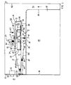
- the radial fan 2 preferably has one along an axis of rotation A. extended (elongated) shaft 22 and one on it Shank 22 attached, preferably symmetrical to the axis of rotation A trained base plate (carrier plate, partition plate) 21 on.
- the base plate 21 is in a directly on the Shaft 22 adjoining inner region dome-shaped (funnel-shaped) indented and in the outside area formed essentially flat.
- cooling air guide vanes 20 provided on the base plate 21st attached or molded from this and essentially perpendicularly from the base plate 21 to one Cooling air intake opening 30 in the housing wall 31 of the blower chamber 3 stand out.
- the cooling air intake opening 30 is on the housing cover 33 facing away from the furnace muffle 10 Housing wall 31 of the blower chamber 3 is provided and can especially at the foot of one formed with the housing wall Suction funnel 32 may be arranged.
- In one of the oven muffle 10 facing housing base 34 of the housing wall 31 at least one vapor suction opening 36 is formed.
- This Vapor suction opening 36 is via a vapor channel 4 with a Vapor outlet opening 18 in the muffle top 17 of the Furnace muffle 10 connected.
- the cooling air intake opening 30, the vapor intake opening 36 and the vapor outlet opening 18 each essentially to the center Axis of rotation A and preferably also rotationally symmetrical to the axis of rotation A.
- the radial fan 2 instructs its base plate 21 to the vapor intake opening 36 further Fan impeller blades, which are called vapor guide blades 25 are designated.
- the wall 31 of the blower chamber 3 has another one Opening that is not axial to the axis of rotation A, but perpendicular to it in the radial direction to the front of the oven is directed towards and referred to as blow-out opening 37 is. Otherwise, the wall 31 of the blower chamber 3 in particular the side wall 35 with respect to the circumferential direction the axis of rotation A around the radial fan 2, closed. Via a shaft 22 of the radial fan 2 connected holding device 60 is an electric drive motor 6 for rotating the radial fan 2 around its Axis of rotation A attached.
- vapor channel 4 Furthermore is within of the vapor channel 4 an upward from the vapor outlet opening 18 extending vapors 41 formed, around which a channel-shaped condensate collecting area 42 is formed is. This has the advantage of being in the colder areas of the duct wall 40 condensing vapor condensate can collect in the condensate collection area 42 and not in the muffle interior 15 and on the inside Food can drip.
- vapors 25 vapors marked W air from the muffle interior, enriched with cooking and fat vapors in the cooking mode is
- K1 Fresh air from the outside 11 outside the Oven housing 83 sucked axially.
- the sucked in steam W flows successively through the vapor outlet opening 18, the vapor channel 4 and the vapor intake opening 36, the announced one Fresh air K1 successively through the fresh air duct 8 and the vapor intake opening 36.
- the mixture of vapor W and fresh air K1 is radial from the radial fan 2 directed outwards and completely through the blow-out opening 37 blown out of the blower chamber 3.
- Control panel 50 with one or more control elements 51 and arranged behind the control panel 50 and with the Controls 51 connected controls 52, in particular may contain electronic components arranged.
- the fresh air K1 has the function of the vapor W to dilute and thus contaminate the front 12 of the oven or in the air flow in from the air outlet opening 55 escaping airflow located objects to reduce, and on the other hand also a cooling function for the front area of the oven around the fresh air duct 8 and also the area around the diversion channel 5, since with the cool fresh air K1 also the mixture K1 + K2 + W in its Temperature is reduced.
- the ratio R1 VK1 / VW des Volume flow VK1 of fresh air K1 to volume flow VW des Wrasens W is determined by the dimensions of the fresh air duct 8 and the vapor channel 4 with the associated inlet openings 55 or 18 determined and can be varied within a wide range become.
- the ratio R1 of the volume flows of fresh air K1 and Wrasen W is preferably in a range between 1 and 5 (1 ⁇ R1 ⁇ 5).
- volume flows VK1 and VW are selected as follows:
- the volume flow of the vapor W is generally between 2 m 3 / h and 10 m 3 / h and the volume flow VK1 of the fresh air K1 is between 2 m 3 / h and 50 m 3 / h .
- the cooling air intake opening 30 in the blower chamber 3 is eliminated.
- the blower 2 is then no longer used to cool the other areas of the oven, but only the area around the fresh air duct 8 and also the discharge duct 5.
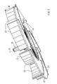
- FIG. 2 shows a side perspective view of a Oven from above, in which the blower chamber 3 by one Housing wall 31 is surrounded by the of the discharge opening 37 side facing substantially cylindrical is designed and towards the blow-out opening 37, for example linear, expanding.
- FIG Intake funnel 32 with the cooling air intake opening 30, the fastening device 60 on the radial fan 2 for the not shown drive motor and the cooling air guide vanes 20 and the base plate 21 of the radial fan located below to see.
- the diversion channel which is actually hidden in FIG.
- 2 5 is through a baffle 58 in two partial flow channels divided by a share of each Mixture K1 + K2 + W from fresh air K1, cooling air K2 and vapors W each a blow-out opening (air passage area) 56th or 57 supplied on or under the control panel 50 and is blown out into the outer space 11 there.
- the diversion channel 5 also widens towards the blow-out openings 56 and 57 in width, so it is in the form of a diffuser.
- a fresh air duct 8 is indicated, whose width varies from one to the width of the Control panel 50 extending air inlet opening 59 to Vapor channel 4 reduced.
- the air inlet opening 59 of the Fresh air duct 8 for transporting fresh air K1 to Radial fan 2 is below the two blow-out openings 56 and 57 arranged.
- the location and number of air intake openings 59 for the fresh air duct 8 can be varied.
- one or more air inlet openings 59 also laterally offset to the blow-out openings, e.g. 56 and 57, of the discharge channel 5, for example in the middle below the deflector 58. This will Air sucked in the middle of the front 12 of the oven and blown out on both sides. This makes possible For example, the targeted cooling of only one in the Middle door handle of a not shown Oven door.
- the fresh air duct 8 is then each in its Shape adapted accordingly to the air inlet openings 59.
- the housing wall 31 of the blower chamber 3 can preferably also be formed spirally in a manner known per se, for example from DE 42 11 755 A1 .
- the housing wall 31 of the blower chamber 3 and the walls of the channels 4, 5 and 8 are preferably formed with sheets, in particular steel sheets.
- FIG. 3 shows the radial fan in a more detailed view 2.
- the cooling air guide vanes 20 and opposite side of the base plate 21, the vapor guide vanes 25 recognizable.
- the cooling air guide vanes 20 and the vapor guide vanes 25 are parallel to the projection Axis of rotation A congruent one above the other and each in the same direction with respect to the radial direction to Axis of rotation A and the shaft 22 curved, in particular all convex or all concave.
- cooling air guide vanes As special A backward curvature of the cooling air guide vanes has been found to be advantageous 20 and the vapor guide vane 25 proved in the case of an imaginary radial line from the axis of rotation A to the outside through a cooling air guide vane 20 or a vapor guide vane 25 extends all radially outer areas of the corresponding cooling air guide vane 20 or vapor guide vane 25 in the direction of rotation are moved forward.
- the cooling air guide vanes 20 and the vapor guide vanes 25 can also be offset from one another in the circumferential direction, so not be congruent with each other. Can also a different number or shape of cooling air guide vanes 20 and vapor guide vanes 25 on the base plate 21 and / or the cooling air guide vanes 20 and / or the vapor guide vanes 25 also in mutually different ones Distances from each other (asymmetrical Arrangement), then on a corresponding The resulting imbalance must be compensated for. Finally, it can also be used to increase the suction effect one, in particular annular, cover the Cooling air guide vanes 20 may be provided upwards, so that the spaces between the cooling air guide vanes 20 down from the base plate 21 and up are completed by the cover.
- the radial fan 2 can in particular consist of a coherent Be formed body, for example a sheet metal body, in which the cooling air guide vanes 20 and the vapor guide vanes 25 on a base plate 21 made of sheet metal a connection technology are applied, or by punching and bending up sheet metal material are formed. Furthermore, the radial fan 2 can also be made of a temperature-resistant Plastic consist, for example, by Injection molded body.
- the ratio R2 is set in particular in a range between approximately 2 and 25 and preferably between approximately 5 and approximately 18.
- the radial blower 2 simultaneously aspirates the smallest possible amount of vapor from the muffle interior 15 and a comparatively large amount of cooling air from the interior of the housing outside the furnace muffle 10.
- the cooling air intake opening 30 is preferably centric arranged to the axis of rotation A, is in the simplest embodiment circular disk-shaped and has one smaller diameter than the radial diameter of the Radial blower 2.
- Regarding the shape of the cooling air guide vanes 20 has a backward curved shape the associated lower noise level proven. However, there are other forms of the cooling air guide vanes 20 possible.
- the height is particularly important the cooling air guide vanes 20, i.e. their dimensions parallel to the axis of rotation A, which is denoted by H in FIG.
- This height H of the cooling air guide vanes 20 is generally between about 4 mm and about 30 mm, especially between about 10 mm and about 20 mm and preferably between about 15 mm and about 20 mm, for example about 17.5 mm.
- the distance between the radial fan 2 and the cooling air intake opening 30 is generally set to a value between about 4 mm and 10 mm and in particular between 5 mm and about 8 mm set depending on the operating speed of the radial fan 2.
- At an operating speed of 1860 RPM (revolutions per minute) has a gap distance proven of about 7 mm.
- the gap distance can be reduced to approx. 5.5 mm, especially with a also reduced speed of 1600 rpm to the to achieve the same cooling air volume flow VK2.
- the vapor guide vanes 25 can in particular like that Cooling air guide vanes 20 can be curved, but can also have a different shape.
- An important parameter is the height of the vapor guide vanes 25, which is denoted by h in FIG is.
- This height h of the vapor guide vane 25 becomes generally chosen between about 1 mm and about 3 mm, in particular about 2 mm, but can also be chosen smaller and in particular only be 0 mm, i.e. that no vapor guide vane 25 are provided and the for suctioning the Wrasen's W required vacuum due to surface friction the base plate 21 of the radial fan 2 is reached.
- the vapor intake opening 36 becomes substantially arranged centrally to the axis of rotation A in order to achieve a uniform To allow suction through the radial fan 2.
- the gap distance is speed-dependent and is generally between about 1 mm and about 4 mm, especially between about 1.5 mm and about 3.5 mm. At a speed of 1600 rpm (without ring cover 1860 rpm) Proven gap distance of 3 mm.
- the vapor guide vanes 25 allow a greater tolerance in the choice of the gap distance, without backing up under the radial fan 2 into the muffle interior 15, a tilting of the ventilation system (Reversal of the flow direction). Thereby the system is less sensitive to manufacturing tolerances.
- the arrangement of the radial fan 2 directly above the vapor outlet opening 18 and the resultant direct vapor extraction can adjust the amount of vapors exactly to the targets become.
- blades can be used as radial fans 2 also be provided with a drum fan radial guide vanes.
- vapor intake opening 36 or blow-out opening 37 instead of only one cooling air intake opening 30, vapor intake opening 36 or blow-out opening 37 also each corresponding Openings may be provided, for example in the form of a Hole pattern.
- FIG 4 shows a development of the embodiment according to FIG 1, in which the fresh air K1 in addition to cooling a Door 9 to close the loading opening 16 of the Furnace muffle 10 is used.
- the door 9 has an upper Area a door handle 91 for handling the door 9 and between a front and a back, which is generally each include a viewing window, a door interior 90 on.
- Air inlet openings 93 In a lower area of the door 9 are Air inlet openings 93, not shown, and in the area of the door handle 91 a further air inlet opening 95 is provided.
- an air outlet opening 94 is directly opposite the air passage opening 55 of the fresh air duct 8 intended.
- both fresh air from the blower 2 K1 passed around the door handle 91 and through the air inlet opening 95 and the air outlet opening 94 in the fresh air duct 8 sucked as well as from below through the air inlet openings 93
- Fresh air K1 through door interior 90 and likewise through the air outlet opening 94 into the fresh air duct 8 of the oven.
- the fresh air K1 therefore cools both the door handle 91 and the door interior 90 and thus also the door front.
- the fresh air duct 8 is in this Design on the door 9 extended towards the front, see above that a multiple flow paths (sub-channels) comprehensive Fresh air duct is created.
- the fresh air duct in the door 9 can be varied in a variety of ways.
- the Exhaust air K1 + K2 + W emerging from the discharge duct 5 becomes led out into the outer frame 11 above the door 9.
Landscapes
- Engineering & Computer Science (AREA)
- Chemical & Material Sciences (AREA)
- Combustion & Propulsion (AREA)
- Mechanical Engineering (AREA)
- General Engineering & Computer Science (AREA)
- Electric Ovens (AREA)
- Electric Stoves And Ranges (AREA)
Applications Claiming Priority (2)
| Application Number | Priority Date | Filing Date | Title |
|---|---|---|---|
| DE19920345 | 1999-05-04 | ||
| DE19920345A DE19920345C1 (de) | 1999-05-04 | 1999-05-04 | Garofen mit Wrasenabführung und Frischluftbeimischung |
Publications (3)
| Publication Number | Publication Date |
|---|---|
| EP1050718A2 true EP1050718A2 (fr) | 2000-11-08 |
| EP1050718A3 EP1050718A3 (fr) | 2002-04-03 |
| EP1050718B1 EP1050718B1 (fr) | 2004-09-22 |
Family
ID=7906838
Family Applications (1)
| Application Number | Title | Priority Date | Filing Date |
|---|---|---|---|
| EP99121986A Expired - Lifetime EP1050718B1 (fr) | 1999-05-04 | 1999-11-10 | Four avec dispositif de d'extraction de la buée et d'adjonction d'air frais |
Country Status (2)
| Country | Link |
|---|---|
| EP (1) | EP1050718B1 (fr) |
| DE (2) | DE19920345C1 (fr) |
Cited By (12)
| Publication number | Priority date | Publication date | Assignee | Title |
|---|---|---|---|---|
| WO2002046662A1 (fr) * | 2000-12-04 | 2002-06-13 | BSH Bosch und Siemens Hausgeräte GmbH | Dispositif de cuisson |
| EP1867928A1 (fr) * | 2006-06-15 | 2007-12-19 | Brandt Industries | Four de cuisson à la vapeur |
| FR2906871A1 (fr) * | 2006-10-05 | 2008-04-11 | Brandt Ind Sas | Porte de four de cuisson comprenant un canal d'air. |
| ES2331392A1 (es) * | 2007-06-29 | 2009-12-30 | Bsh Electrodomesticos España, S.A. | Aparato de coccion. |
| US20110186030A1 (en) * | 2007-03-29 | 2011-08-04 | Electrolux Home Products Corporation N.V. | Cooking oven and method for operating the same |
| ITTO20130847A1 (it) * | 2013-10-18 | 2015-04-19 | Indesit Co Spa | Apparecchio di cottura domestico |
| ITTO20130849A1 (it) * | 2013-10-18 | 2015-04-19 | Indesit Co Spa | Apparecchio di cottura domestico |
| ITTO20130852A1 (it) * | 2013-10-18 | 2015-04-19 | Indesit Co Spa | Apparecchio di cottura domestico |
| EP1892479A3 (fr) * | 2006-08-21 | 2017-11-01 | BSH Hausgeräte GmbH | Appareil de cuisson |
| DE102016211585A1 (de) | 2016-06-28 | 2017-12-28 | BSH Hausgeräte GmbH | Haushaltsgargerät |
| WO2020030650A1 (fr) * | 2018-08-10 | 2020-02-13 | Electrolux Appliances Aktiebolag | Système de refroidissement pour four de cuisson |
| CN112746980A (zh) * | 2020-12-31 | 2021-05-04 | 深圳市银星智能科技股份有限公司 | 风机组件及清洁机器人 |
Families Citing this family (2)
| Publication number | Priority date | Publication date | Assignee | Title |
|---|---|---|---|---|
| DE102004008465A1 (de) | 2004-02-20 | 2005-09-08 | Electrolux Home Products Corporation N.V. | Verfahren und Vorrichtung zum Be- und/oder Entlüften eines Garofens |
| DE102004008463B3 (de) * | 2004-02-20 | 2005-03-10 | Electrolux Home Prod Corp | Verfahren und eine Vorrichtung zum Be- und/oder Entlüften eines Garofens |
Citations (8)
| Publication number | Priority date | Publication date | Assignee | Title |
|---|---|---|---|---|
| US4331124A (en) * | 1979-07-02 | 1982-05-25 | Raytheon Company | Flue aspirated oven |
| DE8706668U1 (fr) * | 1987-05-08 | 1987-07-02 | Bosch-Siemens Hausgeraete Gmbh, 8000 Muenchen, De | |
| FR2673268A1 (fr) * | 1991-02-21 | 1992-08-28 | Scholtes Ets Eugen | Four de cuisson electrique a usage domestique. |
| EP0663568A1 (fr) * | 1994-01-12 | 1995-07-19 | Société SCHOLTES | Four de cuisson domestique |
| US5500508A (en) * | 1992-11-16 | 1996-03-19 | Bosch-Siemens Hausgeraete Gmbh | Oven, particularly with an apparatus for pyroltic self cleaning |
| EP0752561A1 (fr) * | 1995-07-04 | 1997-01-08 | Bosch-Siemens HausgerÀ¤te GmbH | Fuir de cuisson |
| EP0900985A1 (fr) * | 1997-09-04 | 1999-03-10 | AEG Hausgeräte GmbH | Méthode pour refroidir la porte d'un four et four à dispositif de refroidissement |
| DE19738601C1 (de) * | 1997-09-04 | 1999-03-18 | Aeg Hausgeraete Gmbh | Verfahren zum Kühlen der Außenumgebung einer Ofenmuffel |
Family Cites Families (6)
| Publication number | Priority date | Publication date | Assignee | Title |
|---|---|---|---|---|
| DE3346019C2 (de) * | 1983-12-20 | 1985-11-07 | Bosch-Siemens Hausgeraete Gmbh, 7000 Stuttgart | Backofen |
| DE3516847C3 (de) * | 1985-05-10 | 1995-02-23 | Miele & Cie | Elektroherd mit Katalysator |
| IT8819599A0 (it) * | 1988-03-01 | 1988-03-01 | Ocean Spa | Forno da cucina per la cottura di alimenti, del tipo da incasso in mobili da cucina modulari. |
| DE3839657C2 (de) * | 1988-11-24 | 1993-11-18 | Miele & Cie | Luftführungssystem für einen Backofen |
| DE4211755A1 (de) * | 1992-04-08 | 1993-10-14 | Licentia Gmbh | Back- und Bratofen mit einer Kühlabluft- und Wrasenabzugseinrichtung |
| DE4322360A1 (de) * | 1993-07-05 | 1995-01-12 | Bosch Siemens Hausgeraete | Einbauherd |
-
1999
- 1999-05-04 DE DE19920345A patent/DE19920345C1/de not_active Expired - Fee Related
- 1999-11-10 EP EP99121986A patent/EP1050718B1/fr not_active Expired - Lifetime
- 1999-11-10 DE DE59910584T patent/DE59910584D1/de not_active Expired - Lifetime
Patent Citations (8)
| Publication number | Priority date | Publication date | Assignee | Title |
|---|---|---|---|---|
| US4331124A (en) * | 1979-07-02 | 1982-05-25 | Raytheon Company | Flue aspirated oven |
| DE8706668U1 (fr) * | 1987-05-08 | 1987-07-02 | Bosch-Siemens Hausgeraete Gmbh, 8000 Muenchen, De | |
| FR2673268A1 (fr) * | 1991-02-21 | 1992-08-28 | Scholtes Ets Eugen | Four de cuisson electrique a usage domestique. |
| US5500508A (en) * | 1992-11-16 | 1996-03-19 | Bosch-Siemens Hausgeraete Gmbh | Oven, particularly with an apparatus for pyroltic self cleaning |
| EP0663568A1 (fr) * | 1994-01-12 | 1995-07-19 | Société SCHOLTES | Four de cuisson domestique |
| EP0752561A1 (fr) * | 1995-07-04 | 1997-01-08 | Bosch-Siemens HausgerÀ¤te GmbH | Fuir de cuisson |
| EP0900985A1 (fr) * | 1997-09-04 | 1999-03-10 | AEG Hausgeräte GmbH | Méthode pour refroidir la porte d'un four et four à dispositif de refroidissement |
| DE19738601C1 (de) * | 1997-09-04 | 1999-03-18 | Aeg Hausgeraete Gmbh | Verfahren zum Kühlen der Außenumgebung einer Ofenmuffel |
Cited By (25)
| Publication number | Priority date | Publication date | Assignee | Title |
|---|---|---|---|---|
| WO2002046662A1 (fr) * | 2000-12-04 | 2002-06-13 | BSH Bosch und Siemens Hausgeräte GmbH | Dispositif de cuisson |
| US6817282B2 (en) | 2000-12-04 | 2004-11-16 | Bsh Bosch Und Siemens Hausgeraete Gmbh | Cooker |
| EP1867928A1 (fr) * | 2006-06-15 | 2007-12-19 | Brandt Industries | Four de cuisson à la vapeur |
| FR2902500A1 (fr) * | 2006-06-15 | 2007-12-21 | Brandt Ind Sas | Four de cuisson a la vapeur |
| EP1892479A3 (fr) * | 2006-08-21 | 2017-11-01 | BSH Hausgeräte GmbH | Appareil de cuisson |
| FR2906871A1 (fr) * | 2006-10-05 | 2008-04-11 | Brandt Ind Sas | Porte de four de cuisson comprenant un canal d'air. |
| US20110186030A1 (en) * | 2007-03-29 | 2011-08-04 | Electrolux Home Products Corporation N.V. | Cooking oven and method for operating the same |
| ES2331392A1 (es) * | 2007-06-29 | 2009-12-30 | Bsh Electrodomesticos España, S.A. | Aparato de coccion. |
| WO2015056207A1 (fr) * | 2013-10-18 | 2015-04-23 | Indesit Company S.P.A. | Appareil de cuisson à usage domestique |
| EP3058282B1 (fr) | 2013-10-18 | 2018-09-26 | Whirlpool EMEA S.p.A | Appareil electromenager de cuisson |
| WO2015056208A1 (fr) * | 2013-10-18 | 2015-04-23 | Indesit Company S.P.A. | Appareil de cuisson à usage domestique |
| WO2015056206A1 (fr) * | 2013-10-18 | 2015-04-23 | Indesit Company S.P.A. | Appareil de cuisson à usage domestique |
| ITTO20130849A1 (it) * | 2013-10-18 | 2015-04-19 | Indesit Co Spa | Apparecchio di cottura domestico |
| CN105814366A (zh) * | 2013-10-18 | 2016-07-27 | 盈得喜股份有限公司 | 家用烹调用具 |
| CN106030213A (zh) * | 2013-10-18 | 2016-10-12 | 盈得喜股份有限公司 | 家用烹调用具 |
| ITTO20130847A1 (it) * | 2013-10-18 | 2015-04-19 | Indesit Co Spa | Apparecchio di cottura domestico |
| US11092344B2 (en) | 2013-10-18 | 2021-08-17 | Whirlpool Emea S.P.A. | Household cooking appliance |
| ITTO20130852A1 (it) * | 2013-10-18 | 2015-04-19 | Indesit Co Spa | Apparecchio di cottura domestico |
| US10260759B2 (en) | 2013-10-18 | 2019-04-16 | Whirlpool EMEA S.p.A | Household cooking appliance |
| US10260758B2 (en) | 2013-10-18 | 2019-04-16 | Whirlpool Emea S.P.A. | Household cooking appliance |
| DE102016211585A1 (de) | 2016-06-28 | 2017-12-28 | BSH Hausgeräte GmbH | Haushaltsgargerät |
| WO2020030650A1 (fr) * | 2018-08-10 | 2020-02-13 | Electrolux Appliances Aktiebolag | Système de refroidissement pour four de cuisson |
| US20210315070A1 (en) * | 2018-08-10 | 2021-10-07 | Electrolux Appliances Aktiebolag | Cooling system for a cooking oven |
| CN112746980A (zh) * | 2020-12-31 | 2021-05-04 | 深圳市银星智能科技股份有限公司 | 风机组件及清洁机器人 |
| CN112746980B (zh) * | 2020-12-31 | 2022-09-13 | 深圳银星智能集团股份有限公司 | 风机组件及清洁机器人 |
Also Published As
| Publication number | Publication date |
|---|---|
| DE19920345C1 (de) | 2000-12-21 |
| EP1050718A3 (fr) | 2002-04-03 |
| DE59910584D1 (de) | 2004-10-28 |
| EP1050718B1 (fr) | 2004-09-22 |
Similar Documents
| Publication | Publication Date | Title |
|---|---|---|
| EP1004826B1 (fr) | Four avec dispositif de refroidissement et d'extraction de la buée | |
| EP1050718B1 (fr) | Four avec dispositif de d'extraction de la buée et d'adjonction d'air frais | |
| DE60308134T2 (de) | Wandmontierter Mikrowellenherd | |
| DE69908706T2 (de) | Kombinierter Mikrowellenofen und Absaugvorrichtung | |
| EP1194721B1 (fr) | Dispositif d'aspiration d'air pour poste de travail | |
| EP0752561A1 (fr) | Fuir de cuisson | |
| DE19939673B4 (de) | Garofen mit Auslaßphase | |
| EP3827204A2 (fr) | Dispositif d'évacuation de vapeur | |
| DE60306322T2 (de) | Wandbefestigter Mikrowellenherd | |
| EP1686322B1 (fr) | Appareil de cuisson | |
| EP0942235B1 (fr) | Feu de boulanger avec boíte d'aspiration | |
| EP0726425B1 (fr) | Four de boulanger à encastrer - refroidissement | |
| DE2615604A1 (de) | Backofen, insbesondere mit mitteln zur pyrolytischen reinigung | |
| EP0886112A2 (fr) | Hotte combinée pour l'évacuation de fumée et le conditionnement d'air | |
| EP0003764B1 (fr) | Four de cuisson double, en particulier four de cuisson encastré | |
| DE2656565B2 (de) | Backofen mit einem Wrasenabzugskanal | |
| EP1306623B2 (fr) | Cuisinière avec un dispositif de ventilation | |
| DE102011006075A1 (de) | Gargerät mit Kühlluftführung | |
| EP1014002B1 (fr) | Cuisinière, en particulier cuisinière électrique | |
| DE602005003275T2 (de) | Mikrowellenofen und Lüfteranlage für Mikrowellenofen | |
| EP4165349A1 (fr) | Appareil d'extraction, et agencement de cuisine doté d'une cuisinière et d'un appareil d'extraction | |
| DE2167022A1 (de) | Haushaltbackofen | |
| CH680040A5 (en) | Domestic extractor fan with tubular air duct - has radial ventilator at one end, wheel with suction duct, and air outlet | |
| EP0393447A1 (fr) | Fourneau électrique à circulation d'air de chauffage | |
| EP3421806A1 (fr) | Ventilateur |
Legal Events
| Date | Code | Title | Description |
|---|---|---|---|
| PUAI | Public reference made under article 153(3) epc to a published international application that has entered the european phase |
Free format text: ORIGINAL CODE: 0009012 |
|
| AK | Designated contracting states |
Kind code of ref document: A2 Designated state(s): AT BE CH CY DE DK ES FI FR GB GR IE IT LI LU MC NL PT SE Kind code of ref document: A2 Designated state(s): DE FR GB IT |
|
| AX | Request for extension of the european patent |
Free format text: AL;LT;LV;MK;RO;SI |
|
| PUAL | Search report despatched |
Free format text: ORIGINAL CODE: 0009013 |
|
| AK | Designated contracting states |
Kind code of ref document: A3 Designated state(s): AT BE CH CY DE DK ES FI FR GB GR IE IT LI LU MC NL PT SE |
|
| AX | Request for extension of the european patent |
Free format text: AL;LT;LV;MK;RO;SI |
|
| 17P | Request for examination filed |
Effective date: 20020419 |
|
| AKX | Designation fees paid |
Free format text: DE FR GB IT |
|
| 17Q | First examination report despatched |
Effective date: 20030711 |
|
| GRAP | Despatch of communication of intention to grant a patent |
Free format text: ORIGINAL CODE: EPIDOSNIGR1 |
|
| GRAS | Grant fee paid |
Free format text: ORIGINAL CODE: EPIDOSNIGR3 |
|
| GRAA | (expected) grant |
Free format text: ORIGINAL CODE: 0009210 |
|
| AK | Designated contracting states |
Kind code of ref document: B1 Designated state(s): DE FR GB IT |
|
| REG | Reference to a national code |
Ref country code: GB Ref legal event code: FG4D Free format text: NOT ENGLISH |
|
| REG | Reference to a national code |
Ref country code: IE Ref legal event code: FG4D Free format text: GERMAN |
|
| REF | Corresponds to: |
Ref document number: 59910584 Country of ref document: DE Date of ref document: 20041028 Kind code of ref document: P |
|
| GBT | Gb: translation of ep patent filed (gb section 77(6)(a)/1977) |
Effective date: 20050111 |
|
| REG | Reference to a national code |
Ref country code: IE Ref legal event code: FD4D |
|
| PLBE | No opposition filed within time limit |
Free format text: ORIGINAL CODE: 0009261 |
|
| STAA | Information on the status of an ep patent application or granted ep patent |
Free format text: STATUS: NO OPPOSITION FILED WITHIN TIME LIMIT |
|
| ET | Fr: translation filed | ||
| 26N | No opposition filed |
Effective date: 20050623 |
|
| PGFP | Annual fee paid to national office [announced via postgrant information from national office to epo] |
Ref country code: GB Payment date: 20091124 Year of fee payment: 11 |
|
| GBPC | Gb: european patent ceased through non-payment of renewal fee |
Effective date: 20101110 |
|
| PG25 | Lapsed in a contracting state [announced via postgrant information from national office to epo] |
Ref country code: GB Free format text: LAPSE BECAUSE OF NON-PAYMENT OF DUE FEES Effective date: 20101110 |
|
| PGFP | Annual fee paid to national office [announced via postgrant information from national office to epo] |
Ref country code: DE Payment date: 20121121 Year of fee payment: 14 |
|
| PGFP | Annual fee paid to national office [announced via postgrant information from national office to epo] |
Ref country code: FR Payment date: 20131120 Year of fee payment: 15 |
|
| REG | Reference to a national code |
Ref country code: DE Ref legal event code: R119 Ref document number: 59910584 Country of ref document: DE Effective date: 20140603 |
|
| PG25 | Lapsed in a contracting state [announced via postgrant information from national office to epo] |
Ref country code: DE Free format text: LAPSE BECAUSE OF NON-PAYMENT OF DUE FEES Effective date: 20140603 |
|
| PGFP | Annual fee paid to national office [announced via postgrant information from national office to epo] |
Ref country code: IT Payment date: 20140630 Year of fee payment: 16 |
|
| REG | Reference to a national code |
Ref country code: FR Ref legal event code: ST Effective date: 20150731 |
|
| PG25 | Lapsed in a contracting state [announced via postgrant information from national office to epo] |
Ref country code: FR Free format text: LAPSE BECAUSE OF NON-PAYMENT OF DUE FEES Effective date: 20141201 |
|
| PG25 | Lapsed in a contracting state [announced via postgrant information from national office to epo] |
Ref country code: IT Free format text: LAPSE BECAUSE OF NON-PAYMENT OF DUE FEES Effective date: 20151110 |