EP1050717B1 - Glühkerze und Verfahren zur Herstellung derselben - Google Patents
Glühkerze und Verfahren zur Herstellung derselben Download PDFInfo
- Publication number
- EP1050717B1 EP1050717B1 EP00108177A EP00108177A EP1050717B1 EP 1050717 B1 EP1050717 B1 EP 1050717B1 EP 00108177 A EP00108177 A EP 00108177A EP 00108177 A EP00108177 A EP 00108177A EP 1050717 B1 EP1050717 B1 EP 1050717B1
- Authority
- EP
- European Patent Office
- Prior art keywords
- heating rod
- glow plug
- region
- insulating
- heating element
- Prior art date
- Legal status (The legal status is an assumption and is not a legal conclusion. Google has not performed a legal analysis and makes no representation as to the accuracy of the status listed.)
- Expired - Lifetime
Links
- 238000004519 manufacturing process Methods 0.000 title claims abstract description 11
- 238000010438 heat treatment Methods 0.000 claims abstract description 72
- 239000000919 ceramic Substances 0.000 claims description 13
- 238000000034 method Methods 0.000 claims description 12
- 238000009413 insulation Methods 0.000 claims description 11
- 238000002485 combustion reaction Methods 0.000 claims description 6
- 239000000463 material Substances 0.000 claims description 6
- 239000004071 soot Substances 0.000 claims description 5
- 238000007789 sealing Methods 0.000 claims description 4
- 230000003197 catalytic effect Effects 0.000 claims description 3
- 230000015572 biosynthetic process Effects 0.000 claims description 2
- 239000011248 coating agent Substances 0.000 claims description 2
- 238000000576 coating method Methods 0.000 claims description 2
- 229920001296 polysiloxane Polymers 0.000 claims description 2
- 238000005096 rolling process Methods 0.000 claims description 2
- 238000003466 welding Methods 0.000 claims description 2
- 239000012777 electrically insulating material Substances 0.000 claims 2
- 239000011810 insulating material Substances 0.000 abstract description 4
- 238000010292 electrical insulation Methods 0.000 abstract description 3
- 229910052751 metal Inorganic materials 0.000 description 7
- 239000002184 metal Substances 0.000 description 7
- 238000002955 isolation Methods 0.000 description 4
- 239000004033 plastic Substances 0.000 description 3
- KDLHZDBZIXYQEI-UHFFFAOYSA-N Palladium Chemical compound [Pd] KDLHZDBZIXYQEI-UHFFFAOYSA-N 0.000 description 2
- 238000005524 ceramic coating Methods 0.000 description 2
- 150000001875 compounds Chemical class 0.000 description 2
- 239000011521 glass Substances 0.000 description 2
- BASFCYQUMIYNBI-UHFFFAOYSA-N platinum Chemical compound [Pt] BASFCYQUMIYNBI-UHFFFAOYSA-N 0.000 description 2
- OKTJSMMVPCPJKN-UHFFFAOYSA-N Carbon Chemical compound [C] OKTJSMMVPCPJKN-UHFFFAOYSA-N 0.000 description 1
- 229910045601 alloy Inorganic materials 0.000 description 1
- 239000000956 alloy Substances 0.000 description 1
- 238000000137 annealing Methods 0.000 description 1
- 229910010293 ceramic material Inorganic materials 0.000 description 1
- 238000010276 construction Methods 0.000 description 1
- 238000001816 cooling Methods 0.000 description 1
- 230000004927 fusion Effects 0.000 description 1
- 239000000156 glass melt Substances 0.000 description 1
- 229910002804 graphite Inorganic materials 0.000 description 1
- 239000010439 graphite Substances 0.000 description 1
- 239000003779 heat-resistant material Substances 0.000 description 1
- 239000011261 inert gas Substances 0.000 description 1
- 238000002347 injection Methods 0.000 description 1
- 239000007924 injection Substances 0.000 description 1
- 238000009434 installation Methods 0.000 description 1
- 229910044991 metal oxide Inorganic materials 0.000 description 1
- 150000004706 metal oxides Chemical class 0.000 description 1
- 238000012986 modification Methods 0.000 description 1
- 230000004048 modification Effects 0.000 description 1
- 239000006060 molten glass Substances 0.000 description 1
- 238000000465 moulding Methods 0.000 description 1
- 238000010137 moulding (plastic) Methods 0.000 description 1
- 230000005405 multipole Effects 0.000 description 1
- 229910052763 palladium Inorganic materials 0.000 description 1
- 229910052697 platinum Inorganic materials 0.000 description 1
- 229920005989 resin Polymers 0.000 description 1
- 239000011347 resin Substances 0.000 description 1
- 229910000679 solder Inorganic materials 0.000 description 1
- 238000007711 solidification Methods 0.000 description 1
- 230000008023 solidification Effects 0.000 description 1
- 229920001169 thermoplastic Polymers 0.000 description 1
- 239000004416 thermosoftening plastic Substances 0.000 description 1
Images






Classifications
-
- F—MECHANICAL ENGINEERING; LIGHTING; HEATING; WEAPONS; BLASTING
- F23—COMBUSTION APPARATUS; COMBUSTION PROCESSES
- F23Q—IGNITION; EXTINGUISHING-DEVICES
- F23Q7/00—Incandescent ignition; Igniters using electrically-produced heat, e.g. lighters for cigarettes; Electrically-heated glowing plugs
- F23Q7/001—Glowing plugs for internal-combustion engines
-
- F—MECHANICAL ENGINEERING; LIGHTING; HEATING; WEAPONS; BLASTING
- F23—COMBUSTION APPARATUS; COMBUSTION PROCESSES
- F23Q—IGNITION; EXTINGUISHING-DEVICES
- F23Q7/00—Incandescent ignition; Igniters using electrically-produced heat, e.g. lighters for cigarettes; Electrically-heated glowing plugs
- F23Q7/001—Glowing plugs for internal-combustion engines
- F23Q2007/004—Manufacturing or assembling methods
-
- F—MECHANICAL ENGINEERING; LIGHTING; HEATING; WEAPONS; BLASTING
- F23—COMBUSTION APPARATUS; COMBUSTION PROCESSES
- F23Q—IGNITION; EXTINGUISHING-DEVICES
- F23Q7/00—Incandescent ignition; Igniters using electrically-produced heat, e.g. lighters for cigarettes; Electrically-heated glowing plugs
- F23Q7/001—Glowing plugs for internal-combustion engines
- F23Q2007/004—Manufacturing or assembling methods
- F23Q2007/007—Manufacturing or assembling methods ion current sensors
Definitions
- the invention relates to a method for producing a Glow plug with a heating element, which is arranged in a glow plug body and one produced by this method Glow plug.
- JP-A-58138923 is a glow plug with a heating element known, in which the electrical insulation of the heating element opposite the external components by means of a ceramic Pipe is made on its inner and outer surfaces with a glassy coating is provided in each case, consisting of a metallic or metallized paste is formed.
- glow plugs a heating rod made of metal with inner pole and with metal glow plug body in such a way that between Schuwandung and glow plug body a heat-resistant electrical insulation in the form of a glass fusion is introduced.
- the glow plug body made of metal and the heating element of metal with their respective Connection and located between the glow plug body and heating element Glass tube placed in a graphite mold and heated in an oven until the glass melts. The connections become electric by ceramic tubes isolated. After cooling and solidification of the molten glass is the glow plug body against the heating element and the connections fixed in isolation.
- the treatment must be carried out in an oven, whereby Another requirement is the use of heat-resistant materials is. Construction precision and functional quality are at this Procedure not to ensure readily, since for example, during the process of distortion of the components is possible.
- the just described technical effort of Creation of glow plugs of this type corresponds to the economic Expenditure.
- the heating element made of ceramic material; this must be in one multi-stage manufacturing process, for the special tools and Devices are necessary, the ceramic to the heating element be shaped, assembled, burned and ground.
- the Keramiksammlungstab must with a support tube can be connected and only then in a conventional Mounting to a finished glow plug to be installed.
- the object underlying the invention is to to provide a method of the type mentioned, opposite the previous manufacturing process is simplified and suitable for mass production of glow plugs.
- a glow plug produced by the process according to the invention as well as other forms of training this glow plug are the subject of claims 2 to 7.
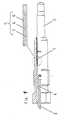
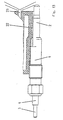
- Figure 1 has the illustrated embodiment of the after this invention Process produced Glow plug a conventional glow plug body 1 made of metal with a standard heating rod 2 from Metal, in the usual way with an inner pole (not shown) and related heating and if necessary, control elements are provided.
- the insulation 5 In Preßsitz Scheme of the body 1 on the heating element 2 is the insulation 5 is formed, this insulation an inner support tube 7 and an outer support tube 8 consists, wherein the inner support tube 7, the heating element 2 fitting surrounds; between the support tube 7 and the concentric around this arranged support tube 8 is an electrical insulating material 6 in the form of a shaped body, a ceramic mass or, for example, an electrically insulating heat-resistant metal oxide such as MgO introduced.
- the body 1 in turn encloses concentrically and at this adjacent the outer support tube. 8
- connections 3, 4 with inner pole or Schuwandung be as cable connections from the connection-side end the glow plug led out.
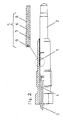
- FIG. 2 essentially corresponds that according to Figure 1, but in one or both End portions of the insulating sleeve 5 O-rings 9, for example made of silicone, as a seal, especially when using powdered insulating, are provided.
- the embodiment of the glow plug according to FIG. 3 has a separate Ionenstrommeßhülse 24, which projects into the combustion area and against both the body 1 by insulation 5 and against the heating element 2 is electrically insulated by insulation 7.
- the Ionenstrommeßhülse 24th perforated so that the plastic mass penetrate into all areas or the trapped air can escape.
- the heating element 2 in the area of the contact surface for Ionenstrommeßhülse 24, for example, ceramic coated. The heating element 2 can then pull in, reduce or Rolls with the Ionenstrommeßhülse 24 are firmly connected.
- the isolation of the Ionenstrommeßhülse 24 opposite the heating element 2 is by the example ceramic coating 7 guaranteed.
- FIG Figure 4 Another embodiment is shown in FIG Figure 4 reproduced, the insulation 5 in Preßsitz Scheme between body 1 and heater 2 as a ceramic coating is formed, wherein the heating element 2 in conventional Pressed way or by reducing, retracting or roles with body 1 is connected.
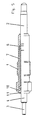
- Figure 5 gives another embodiment again, wherein an inner Switzrohr 7 is provided, the heating element 2 adjacent enclosing, and wherein in the investment area of the inner support tube 7 on the heating element 2, the diameter of the heating element is partially reduced to the Increase installation space for the other adjacent components.
- heating element 2 is firmly anchored in the body 1, is in the connection side Endregion a crimp ring 11 provided on the body 1 such that this the plastic molding 10 on the heating element 2 with Pressed support tube 7 presses and then this on the insulating molding 6 and the body 1 presses. To this Way, the glow plug is sealed and sealed Isolated body 1. The connection of the candle takes place again over the connections 3 and 4.
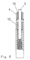
- the further embodiment according to FIG. 6 shows an outer support tube 8 in the interference fit area on, in this area to the connection end the diameter of the heating rod 2, as in the embodiment according to Figure 5, is reduced.
- the insulating Shaped body 6 in the outer support tube 8 and on the heating element. 2 soldered with solder 12, preferably under inert gas or under vacuum.
- the heating element 2 with the soldered components is then pressed into the body 1.
- One in the connection side End portion of the heating element 2 applied sealing ring 15th seals the body 1 with simultaneous isolation of the Heating rod 2 against body 1.
- a contact tube 4 for example, by pulse welding, concentric on the End face of the connection-side end region of the heating element 2 fixed; between the contact tube 4 and inner pole 3 is the Insulation 16 in the form of an insulating tube or insulating compound, for example, MgO provided; the O-ring 13 again isolated and fixes the inner pole 3 relative to the heating element. 2 and at the same time seals the interior of the heating element 2.
- a two-pole or multi-pole plug can be used 17 about the attached with a nut 18 - already standard installed - screw 19 with a glow plug be connected, in which the connection of the inner pole 3 as a conventional pole with threaded end and the Connection of the heating element 2 as over the body 1 protruding Metal tube with collar is formed.
- FIG. 10 has a further embodiment of the Glow plug an insulating, heat-resistant Layer 24, for example made of ceramic, in the area of in the combustion chamber protruding part of the heating element 2 and closes preferably to the insulation 5 between the heating element 2 and the body 1 on.
- this layer covers the heating rod tip, for example, over a range of about 5 to 10 mm, as far as it forms the actual ignition area, not. hereby is achieved that the risk of shunting by reduced or prevented soot formation on the temperature-resistant insulating layer 24 is prevented.
- measuring signals e.g.
- the soot is due to the ambient temperature or the heating element temperature during annealing operation burned down.
- a catalytic Layer 20 is applied, which is the burning of the soot layer in catalyzes this Walkerstab Scheme lower temperature; suitable components of such a catalytic layer 20 may be platinum or palladium or their heat-resistant Compounds or alloys.
- FIG. 12 shows an arrangement in which a glow plug in a cylinder head bore is introduced with an insulating layer or an insulating ceramic tube 21 is provided at 10 and 11 described region of the heating element. 2 because of the low temperatures This Schustab Suitees is endangered by soot.
- FIG. 13 Another arrangement according to Figure 13 has a glow plug, wherein the candle in a cylinder head made of ceramic or another arranged insulating temperature-resistant material is and wherein the ion current, for example between heating element 2 and injector 23 can be measured.
- the advantages of the method according to the invention exist in the areas Manufacturing processes suitable for mass production and can be integrated into the previously customary production; the with the invention Process produced Glow plugs are characterized by low Form and bearing deviations of the components, in particular the mecanicpols, taking the various components and materials like sealing components and insulating materials different Operating temperatures of the respective glow plug area can be adapted; at the same time, the Glow plugs in their combustion chamber side Area an insensitive, large-area electrode for Available, with more accurate and reliable Ionenstrommeßsignale can be achieved. At the same time allow the tubular formed coaxial connections simple connections, in particular of the inner pole.
Landscapes
- Engineering & Computer Science (AREA)
- Chemical & Material Sciences (AREA)
- Combustion & Propulsion (AREA)
- Mechanical Engineering (AREA)
- General Engineering & Computer Science (AREA)
- Resistance Heating (AREA)
- Secondary Cells (AREA)
Description
Claims (7)
- Verfahren zum Herstellen einer Glühkerze mit einem Heizstab, der in einem Glühkerzenkörper angeordnet ist,
dadurch gekennzeichnet, dass eine Isolierhülse gebildet wird, indem zwischen ein inneres Stützrohr (7) und ein äußeres Stützrohr (8) ein elektrisch isolierender Formkörper (6), beispielsweise aus Mgo oder einem keramischen Material, einreduziert wird, dass die Isolierhülse in einen Glühkerzenkörper (1) eingepresst wird, dass anschließend ein Heizstab (2) in die Isolierhülse gepresst wird, woraufhin das Bauteil aus Heizstab und Isolierhülse mit dem Glühkerzenkörper (1) durch Reduzieren, Rollen oder Einziehen verbunden wird und der Bereich des isolierenden Formkörpers (6) mit O-Ringen (9), beispielsweise aus Silikon an wenigstens einem Ende der Stützrohre (7, 8) abgeschlossen wird. - Glühkerze hergestellt nach dem Verfahren nach Anspruch 1,
dadurch gekennzeichnet, dass der isolierende Formkörper (6) zwischen dem inneren (7) und dem äußeren (8) Stützrohr eingebracht ist, wobei das innere Stützrohr (7) den Heizstab (2) anliegend umgibt, und der Kerzenkörper (1) das äußere Stützrohr (8) anliegend umgibt, und endseitig zwischen den Stützrohren (7, 8) der O-Ring oder die O-Ringe (9) als Abdichtung angeordnet sind. - Glühkerze nach Anspruch 2,
dadurch gekennzeichnet, dass im anschlussseitigen Bereich der elektrische Anschluss an die Wandung des Heizstabes (2) durch einen Rohrabschnitt (4) als Kontaktrohr vorgesehen ist, dessen eines Ende in einer angepassten Ausbohrung im Endbereich der Heizstabwandung angeordnet ist, wobei ein O-Ring (13) den Innenraum des Heizstabes (2) abdichtet und gleichzeitig das Kontaktrohr (4) gegen den Innenpol (3) elektrisch isoliert. - Glühkerze nach einem der Ansprüche 2 und 3,
dadurch gekennzeichnet, dass im anschlussseitigen Endbereich des Heizstabes (2) ein Kontaktrohr (4) beispielsweise durch Punktschweißung fixiert ist, das gegenüber den sich durch das Kontaktrohr erstreckenden Innenpol durch eingebrachtes elektrisch isolierendes Material elektrisch isoliert ist, wobei ggf. ein O-Ring zur Abdichtung des Innenraumes des Heizstabes (2) und zur elektrisch isolierenden Positionierung des Innenpols (3) vorgesehen ist. - Glühkerze nach einem der Ansprüche 2 bis 4,
dadurch gekennzeichnet, dass eine Ionenstrommesshülse (24) konzentrisch um den in den Brennraum ragenden Bereich des Heizstabes (2) vorgesehen ist, die sowohl gegen den Glühkerzenkörper (1) als auch gegen den Heizstab (2) isoliert ist, wobei die Isolierung gegen den Heizstab (2) auf dem Anlagebereich der Ionenstrommesshülse (24) am Heizstab (2) als keramische Beschichtung ausgebildet ist. - Glühkerze nach einem der Ansprüche 2 bis 5,
dadurch gekennzeichnet, dass der in den Brennraum ragende Bereich des Heizstabes (2), ausschließlich der Heizstabspitze als Zündbereich, mit einem hitzebeständigen elektrisch isolierenden Material (24), vorzugsweise keramischen Material, beschichtet ist. - Glühkerze nach einem der Ansprüche 2 bis 5,
dadurch gekennzeichnet, dass der in den Brennraum ragende Bereich des Heizstabes (2), ausschließlich der Heizstabspitze als Zündbereich, mit einer Schicht versehen ist, die katalytisches Material zur Verhinderung einer Rußschicht enthält oder daraus besteht.
Applications Claiming Priority (2)
| Application Number | Priority Date | Filing Date | Title |
|---|---|---|---|
| DE19920766 | 1999-05-05 | ||
| DE19920766A DE19920766C1 (de) | 1999-05-05 | 1999-05-05 | Glühkerze und Verfahren zur Herstellung derselben |
Publications (2)
| Publication Number | Publication Date |
|---|---|
| EP1050717A1 EP1050717A1 (de) | 2000-11-08 |
| EP1050717B1 true EP1050717B1 (de) | 2005-06-29 |
Family
ID=7907113
Family Applications (1)
| Application Number | Title | Priority Date | Filing Date |
|---|---|---|---|
| EP00108177A Expired - Lifetime EP1050717B1 (de) | 1999-05-05 | 2000-04-13 | Glühkerze und Verfahren zur Herstellung derselben |
Country Status (7)
| Country | Link |
|---|---|
| US (1) | US6392199B1 (de) |
| EP (1) | EP1050717B1 (de) |
| JP (1) | JP4658285B2 (de) |
| KR (1) | KR100708294B1 (de) |
| AT (1) | ATE298869T1 (de) |
| DE (2) | DE19920766C1 (de) |
| ES (1) | ES2239958T3 (de) |
Cited By (1)
| Publication number | Priority date | Publication date | Assignee | Title |
|---|---|---|---|---|
| DE102009050288A1 (de) * | 2009-10-15 | 2011-04-21 | Beru Ag | Elektrisch beheizbare Sprühdüse |
Families Citing this family (9)
| Publication number | Priority date | Publication date | Assignee | Title |
|---|---|---|---|---|
| DK1141350T3 (da) * | 1998-12-22 | 2010-11-08 | Dow Agrosciences Llc | Fremgangsmåde og genetiske sammensætninger til begrænsning af udkrydsning og uønskede genstrømme i nytteplanter |
| DE60103731T2 (de) | 2001-03-14 | 2004-10-14 | Federal-Mogul Ignition S.R.L. | Glühkerze zur Messung des Ionisationsstromes einer Kraftmaschine und sein Herstellungsverfahren |
| DE10117641C2 (de) * | 2001-04-09 | 2003-02-27 | Beru Ag | Stabglühkerze |
| EP2198201A2 (de) * | 2007-09-23 | 2010-06-23 | Saint-Gobain Ceramics & Plastics, Inc. | Heizelementsysteme |
| FR2928688B1 (fr) * | 2008-03-17 | 2016-02-05 | Faurecia Sys Echappement | Vaporisateur de carburant pour ligne d'echappement de vehicule automobile. |
| EP2469256B1 (de) * | 2010-12-22 | 2016-09-21 | HIDRIA AET Druzba za proizvodnjo vzignih sistemov in elektronike d.o.o. | Zündkerze mit Lastsensor und gesiebter Sensorverknüpfung |
| KR101634093B1 (ko) * | 2012-08-09 | 2016-06-28 | 봇슈 가부시키가이샤 | 압력 센서 일체형 글로 플러그 |
| HUP1700051A2 (hu) * | 2017-02-02 | 2018-08-28 | Equip Test Kft | Kontaktáló eszköz, fejegység ahhoz, valamint eljárások kontaktáló eszköz és fejegység elõállítására |
| CN120400487B (zh) * | 2025-05-29 | 2026-04-03 | 浙江日星标准件有限公司 | 一种螺栓紧固件用卧式回火炉 |
Family Cites Families (19)
| Publication number | Priority date | Publication date | Assignee | Title |
|---|---|---|---|---|
| JPS58119047U (ja) * | 1981-12-28 | 1983-08-13 | 日本特殊陶業株式会社 | 二線式グロ−プラグ |
| JPS58138923A (ja) * | 1982-02-12 | 1983-08-18 | Ngk Spark Plug Co Ltd | 二線式グロ−プラグ |
| US4475029A (en) * | 1982-03-02 | 1984-10-02 | Nippondenso Co., Ltd. | Ceramic heater |
| JPS5966618A (ja) * | 1982-10-06 | 1984-04-16 | Toyota Motor Corp | 触媒付燃焼室部品 |
| JPS5959662U (ja) * | 1982-10-06 | 1984-04-18 | 日本特殊陶業株式会社 | 二線式グロ−プラグ |
| JPS5959664U (ja) * | 1982-10-06 | 1984-04-18 | 日本特殊陶業株式会社 | 二線式グロ−プラグの発熱チユ−ブ |
| JPS59167635A (ja) * | 1983-03-15 | 1984-09-21 | Toyota Motor Corp | デイ−ゼルエンジンのグロ−プラグ |
| JPS60165681U (ja) * | 1984-04-12 | 1985-11-02 | 日本特殊陶業株式会社 | 二線式セラミツクグロ−プラグ |
| US4661686A (en) * | 1984-04-12 | 1987-04-28 | Ngk Spark Plug Co., Ltd | Dual line ceramic glow plug |
| JP2712198B2 (ja) * | 1987-10-14 | 1998-02-10 | 株式会社デンソー | ディーゼル機関予熱栓用抵抗装置 |
| JPH0742940A (ja) * | 1993-07-29 | 1995-02-10 | Nippondenso Co Ltd | セラミックグロープラグ |
| DE4334771C2 (de) * | 1993-10-12 | 1996-03-28 | Beru Werk Ruprecht Gmbh Co A | Glühkerze |
| DE19511376A1 (de) * | 1995-03-28 | 1996-10-02 | Beru Werk Ruprecht Gmbh Co A | Glühkerze |
| EP0834652B1 (de) * | 1996-04-10 | 2004-10-13 | Denso Corporation | Glühkerze, ihr herstellunsverfahren und ionenstromdetektor |
| JP3834889B2 (ja) * | 1996-09-18 | 2006-10-18 | 株式会社デンソー | グロープラグ |
| EP0989370A3 (de) * | 1998-09-25 | 2005-04-20 | Delphi Technologies, Inc. | Metallspitze für Glühsensor |
| DE19920758C1 (de) * | 1999-05-05 | 2000-12-21 | Beru Ag | Glühkerze und Verfahren zur Herstellung derselben |
| US6215105B1 (en) * | 1999-08-18 | 2001-04-10 | Delphi Technologies, Inc. | Ion sensor glow plug assembly with coating between sheath and shell |
| US6248980B1 (en) * | 1999-08-19 | 2001-06-19 | Delphi Technologies, Inc. | Ion sensor glow plug assembly |
-
1999
- 1999-05-05 DE DE19920766A patent/DE19920766C1/de not_active Expired - Fee Related
-
2000
- 2000-04-13 ES ES00108177T patent/ES2239958T3/es not_active Expired - Lifetime
- 2000-04-13 AT AT00108177T patent/ATE298869T1/de not_active IP Right Cessation
- 2000-04-13 DE DE50010619T patent/DE50010619D1/de not_active Expired - Lifetime
- 2000-04-13 EP EP00108177A patent/EP1050717B1/de not_active Expired - Lifetime
- 2000-05-03 KR KR1020000023792A patent/KR100708294B1/ko not_active Expired - Fee Related
- 2000-05-05 US US09/565,477 patent/US6392199B1/en not_active Expired - Fee Related
- 2000-05-08 JP JP2000134138A patent/JP4658285B2/ja not_active Expired - Fee Related
Cited By (1)
| Publication number | Priority date | Publication date | Assignee | Title |
|---|---|---|---|---|
| DE102009050288A1 (de) * | 2009-10-15 | 2011-04-21 | Beru Ag | Elektrisch beheizbare Sprühdüse |
Also Published As
| Publication number | Publication date |
|---|---|
| US6392199B1 (en) | 2002-05-21 |
| DE19920766C1 (de) | 2000-12-21 |
| EP1050717A1 (de) | 2000-11-08 |
| KR100708294B1 (ko) | 2007-04-16 |
| JP4658285B2 (ja) | 2011-03-23 |
| KR20000077149A (ko) | 2000-12-26 |
| JP2000329344A (ja) | 2000-11-30 |
| ATE298869T1 (de) | 2005-07-15 |
| ES2239958T3 (es) | 2005-10-16 |
| DE50010619D1 (de) | 2005-08-04 |
Similar Documents
| Publication | Publication Date | Title |
|---|---|---|
| DE10212908B4 (de) | Temperatursensor und Herstellungsverfahren dafür | |
| DE102009056057B4 (de) | Glühkerze und Verfahren zu ihrer Herstellung | |
| DE3342753C2 (de) | ||
| EP1050716B1 (de) | Glühkerze und Verfahren zur Herstellung derselben | |
| EP1065446B2 (de) | Keramischer Heizstab und diesen enthaltende Glühkerze und Verfahren zu deren Herstellung | |
| DE60029415T2 (de) | Glühkerze | |
| DE2854071C2 (de) | Zündkerze | |
| DE2900984A1 (de) | Gluehkerze fuer dieselmotoren | |
| DE19920766C1 (de) | Glühkerze und Verfahren zur Herstellung derselben | |
| DE2939725A1 (de) | Galvanischer fuehler fuer den sauerstoffgehalt von abgasen | |
| DE2900914A1 (de) | Elektrisches heizelement und verfahren zu seiner herstellung | |
| WO1998052030A1 (de) | Sensorelementdichtung für einen gasmessfühler | |
| DE3837128A1 (de) | Gluehkerze fuer dieselmotoren | |
| DE2912332A1 (de) | Festelektrolyt-sauerstoffsensor mit elektrisch isoliertem heizelement | |
| DE2816343A1 (de) | Sauerstoffmessfuehler | |
| EP3247941A1 (de) | Glühstiftkerze | |
| EP1463910A1 (de) | Stiftheizer | |
| WO2000019148A1 (de) | Keramische glühstiftkerze | |
| DE3001017A1 (de) | Heisskanalduese fuer eine spritzgussmaschine | |
| DD147391A5 (de) | Elektrische gluehkerze fuer verbrennungsmotoren | |
| DE1295041B (de) | Verfahren und Vorrichtung zur Herstellung eines Thermoelements | |
| DE19615243C1 (de) | Elektrisch betreibbarer, stabförmiger Infrarotstrahler | |
| DE102007053807A1 (de) | Keramische Glühstiftkerze mit verringertem Heizerabstand | |
| DE69013595T2 (de) | Verfahren zur Herstellung einer gasverschmolzenen Entladungsröhre. | |
| AT123603B (de) | Verfahren zur Herstellung von Zündkerzen für Brennkraftmaschinen. |
Legal Events
| Date | Code | Title | Description |
|---|---|---|---|
| PUAI | Public reference made under article 153(3) epc to a published international application that has entered the european phase |
Free format text: ORIGINAL CODE: 0009012 |
|
| AK | Designated contracting states |
Kind code of ref document: A1 Designated state(s): AT BE CH CY DE DK ES FI FR GB GR IE IT LI LU MC NL PT SE |
|
| AX | Request for extension of the european patent |
Free format text: AL;LT;LV;MK;RO;SI |
|
| 17P | Request for examination filed |
Effective date: 20010502 |
|
| AKX | Designation fees paid |
Free format text: AT BE CH CY DE DK ES FI FR GB GR IE IT LI LU MC NL PT SE |
|
| 17Q | First examination report despatched |
Effective date: 20030820 |
|
| GRAP | Despatch of communication of intention to grant a patent |
Free format text: ORIGINAL CODE: EPIDOSNIGR1 |
|
| GRAS | Grant fee paid |
Free format text: ORIGINAL CODE: EPIDOSNIGR3 |
|
| GRAA | (expected) grant |
Free format text: ORIGINAL CODE: 0009210 |
|
| AK | Designated contracting states |
Kind code of ref document: B1 Designated state(s): AT BE CH CY DE DK ES FI FR GB GR IE IT LI LU MC NL PT SE |
|
| PG25 | Lapsed in a contracting state [announced via postgrant information from national office to epo] |
Ref country code: NL Free format text: LAPSE BECAUSE OF FAILURE TO SUBMIT A TRANSLATION OF THE DESCRIPTION OR TO PAY THE FEE WITHIN THE PRESCRIBED TIME-LIMIT Effective date: 20050629 Ref country code: FI Free format text: LAPSE BECAUSE OF FAILURE TO SUBMIT A TRANSLATION OF THE DESCRIPTION OR TO PAY THE FEE WITHIN THE PRESCRIBED TIME-LIMIT Effective date: 20050629 Ref country code: IE Free format text: LAPSE BECAUSE OF FAILURE TO SUBMIT A TRANSLATION OF THE DESCRIPTION OR TO PAY THE FEE WITHIN THE PRESCRIBED TIME-LIMIT Effective date: 20050629 |
|
| REG | Reference to a national code |
Ref country code: GB Ref legal event code: FG4D Free format text: NOT ENGLISH |
|
| REG | Reference to a national code |
Ref country code: CH Ref legal event code: EP |
|
| REF | Corresponds to: |
Ref document number: 50010619 Country of ref document: DE Date of ref document: 20050804 Kind code of ref document: P |
|
| REG | Reference to a national code |
Ref country code: IE Ref legal event code: FG4D Free format text: LANGUAGE OF EP DOCUMENT: GERMAN |
|
| PG25 | Lapsed in a contracting state [announced via postgrant information from national office to epo] |
Ref country code: DK Free format text: LAPSE BECAUSE OF FAILURE TO SUBMIT A TRANSLATION OF THE DESCRIPTION OR TO PAY THE FEE WITHIN THE PRESCRIBED TIME-LIMIT Effective date: 20050929 Ref country code: GR Free format text: LAPSE BECAUSE OF FAILURE TO SUBMIT A TRANSLATION OF THE DESCRIPTION OR TO PAY THE FEE WITHIN THE PRESCRIBED TIME-LIMIT Effective date: 20050929 |
|
| REG | Reference to a national code |
Ref country code: ES Ref legal event code: FG2A Ref document number: 2239958 Country of ref document: ES Kind code of ref document: T3 |
|
| REG | Reference to a national code |
Ref country code: SE Ref legal event code: TRGR |
|
| GBT | Gb: translation of ep patent filed (gb section 77(6)(a)/1977) |
Effective date: 20050929 |
|
| NLV1 | Nl: lapsed or annulled due to failure to fulfill the requirements of art. 29p and 29m of the patents act | ||
| PG25 | Lapsed in a contracting state [announced via postgrant information from national office to epo] |
Ref country code: PT Free format text: LAPSE BECAUSE OF FAILURE TO SUBMIT A TRANSLATION OF THE DESCRIPTION OR TO PAY THE FEE WITHIN THE PRESCRIBED TIME-LIMIT Effective date: 20051207 |
|
| REG | Reference to a national code |
Ref country code: IE Ref legal event code: FD4D |
|
| ET | Fr: translation filed | ||
| PG25 | Lapsed in a contracting state [announced via postgrant information from national office to epo] |
Ref country code: MC Free format text: LAPSE BECAUSE OF NON-PAYMENT OF DUE FEES Effective date: 20060430 Ref country code: LI Free format text: LAPSE BECAUSE OF NON-PAYMENT OF DUE FEES Effective date: 20060430 Ref country code: BE Free format text: LAPSE BECAUSE OF NON-PAYMENT OF DUE FEES Effective date: 20060430 Ref country code: CH Free format text: LAPSE BECAUSE OF NON-PAYMENT OF DUE FEES Effective date: 20060430 |
|
| PLBE | No opposition filed within time limit |
Free format text: ORIGINAL CODE: 0009261 |
|
| STAA | Information on the status of an ep patent application or granted ep patent |
Free format text: STATUS: NO OPPOSITION FILED WITHIN TIME LIMIT |
|
| 26N | No opposition filed |
Effective date: 20060330 |
|
| REG | Reference to a national code |
Ref country code: CH Ref legal event code: PL |
|
| BERE | Be: lapsed |
Owner name: BERU A.G. Effective date: 20060430 |
|
| PG25 | Lapsed in a contracting state [announced via postgrant information from national office to epo] |
Ref country code: LU Free format text: LAPSE BECAUSE OF NON-PAYMENT OF DUE FEES Effective date: 20060413 |
|
| PG25 | Lapsed in a contracting state [announced via postgrant information from national office to epo] |
Ref country code: CY Free format text: LAPSE BECAUSE OF FAILURE TO SUBMIT A TRANSLATION OF THE DESCRIPTION OR TO PAY THE FEE WITHIN THE PRESCRIBED TIME-LIMIT Effective date: 20050629 |
|
| PGFP | Annual fee paid to national office [announced via postgrant information from national office to epo] |
Ref country code: ES Payment date: 20100430 Year of fee payment: 11 Ref country code: FR Payment date: 20100421 Year of fee payment: 11 |
|
| PGFP | Annual fee paid to national office [announced via postgrant information from national office to epo] |
Ref country code: IT Payment date: 20100426 Year of fee payment: 11 Ref country code: AT Payment date: 20100412 Year of fee payment: 11 |
|
| PGFP | Annual fee paid to national office [announced via postgrant information from national office to epo] |
Ref country code: SE Payment date: 20100413 Year of fee payment: 11 Ref country code: GB Payment date: 20100413 Year of fee payment: 11 |
|
| REG | Reference to a national code |
Ref country code: SE Ref legal event code: EUG |
|
| GBPC | Gb: european patent ceased through non-payment of renewal fee |
Effective date: 20110413 |
|
| REG | Reference to a national code |
Ref country code: AT Ref legal event code: MM01 Ref document number: 298869 Country of ref document: AT Kind code of ref document: T Effective date: 20110413 |
|
| REG | Reference to a national code |
Ref country code: FR Ref legal event code: ST Effective date: 20111230 |
|
| PG25 | Lapsed in a contracting state [announced via postgrant information from national office to epo] |
Ref country code: FR Free format text: LAPSE BECAUSE OF NON-PAYMENT OF DUE FEES Effective date: 20110502 |
|
| PG25 | Lapsed in a contracting state [announced via postgrant information from national office to epo] |
Ref country code: AT Free format text: LAPSE BECAUSE OF NON-PAYMENT OF DUE FEES Effective date: 20110413 Ref country code: IT Free format text: LAPSE BECAUSE OF NON-PAYMENT OF DUE FEES Effective date: 20110413 Ref country code: GB Free format text: LAPSE BECAUSE OF NON-PAYMENT OF DUE FEES Effective date: 20110413 |
|
| REG | Reference to a national code |
Ref country code: ES Ref legal event code: FD2A Effective date: 20120604 |
|
| PG25 | Lapsed in a contracting state [announced via postgrant information from national office to epo] |
Ref country code: ES Free format text: LAPSE BECAUSE OF NON-PAYMENT OF DUE FEES Effective date: 20110414 |
|
| PGFP | Annual fee paid to national office [announced via postgrant information from national office to epo] |
Ref country code: DE Payment date: 20120430 Year of fee payment: 13 |
|
| PG25 | Lapsed in a contracting state [announced via postgrant information from national office to epo] |
Ref country code: SE Free format text: LAPSE BECAUSE OF NON-PAYMENT OF DUE FEES Effective date: 20110414 |
|
| REG | Reference to a national code |
Ref country code: DE Ref legal event code: R082 Ref document number: 50010619 Country of ref document: DE Representative=s name: KOTITSCHKE & HEURUNG PARTNERSCHAFT, DE |
|
| PG25 | Lapsed in a contracting state [announced via postgrant information from national office to epo] |
Ref country code: DE Free format text: LAPSE BECAUSE OF NON-PAYMENT OF DUE FEES Effective date: 20131101 |
|
| REG | Reference to a national code |
Ref country code: DE Ref legal event code: R119 Ref document number: 50010619 Country of ref document: DE Effective date: 20131101 |