EP1045121A2 - Contrôle d'une force de traction avec une correction dépendante de la puissance commandée par le conducteur - Google Patents
Contrôle d'une force de traction avec une correction dépendante de la puissance commandée par le conducteur Download PDFInfo
- Publication number
- EP1045121A2 EP1045121A2 EP00107554A EP00107554A EP1045121A2 EP 1045121 A2 EP1045121 A2 EP 1045121A2 EP 00107554 A EP00107554 A EP 00107554A EP 00107554 A EP00107554 A EP 00107554A EP 1045121 A2 EP1045121 A2 EP 1045121A2
- Authority
- EP
- European Patent Office
- Prior art keywords
- driving force
- vehicle
- correction
- control system
- operative
- Prior art date
- Legal status (The legal status is an assumption and is not a legal conclusion. Google has not performed a legal analysis and makes no representation as to the accuracy of the status listed.)
- Granted
Links
- 230000004044 response Effects 0.000 claims abstract description 24
- 230000005540 biological transmission Effects 0.000 claims description 28
- 230000001133 acceleration Effects 0.000 claims description 17
- 238000005096 rolling process Methods 0.000 claims description 5
- 230000000994 depressogenic effect Effects 0.000 description 9
- 230000035939 shock Effects 0.000 description 6
- 230000008859 change Effects 0.000 description 4
- 238000010586 diagram Methods 0.000 description 4
- 239000000446 fuel Substances 0.000 description 4
- 230000007246 mechanism Effects 0.000 description 3
- 101150081532 KLK8 gene Proteins 0.000 description 2
- 102100034870 Kallikrein-8 Human genes 0.000 description 2
- 230000000881 depressing effect Effects 0.000 description 2
- 230000006870 function Effects 0.000 description 2
- 238000012986 modification Methods 0.000 description 2
- 230000004048 modification Effects 0.000 description 2
- 238000006243 chemical reaction Methods 0.000 description 1
- 238000002485 combustion reaction Methods 0.000 description 1
- 230000001419 dependent effect Effects 0.000 description 1
- 230000010365 information processing Effects 0.000 description 1
- 239000003112 inhibitor Substances 0.000 description 1
- 238000002347 injection Methods 0.000 description 1
- 239000007924 injection Substances 0.000 description 1
- 238000012886 linear function Methods 0.000 description 1
- 238000000034 method Methods 0.000 description 1
- 230000008569 process Effects 0.000 description 1
- 230000009467 reduction Effects 0.000 description 1
- 239000000725 suspension Substances 0.000 description 1
Images


Classifications
-
- F—MECHANICAL ENGINEERING; LIGHTING; HEATING; WEAPONS; BLASTING
- F16—ENGINEERING ELEMENTS AND UNITS; GENERAL MEASURES FOR PRODUCING AND MAINTAINING EFFECTIVE FUNCTIONING OF MACHINES OR INSTALLATIONS; THERMAL INSULATION IN GENERAL
- F16H—GEARING
- F16H61/00—Control functions within control units of change-speed- or reversing-gearings for conveying rotary motion ; Control of exclusively fluid gearing, friction gearing, gearings with endless flexible members or other particular types of gearing
- F16H61/66—Control functions within control units of change-speed- or reversing-gearings for conveying rotary motion ; Control of exclusively fluid gearing, friction gearing, gearings with endless flexible members or other particular types of gearing specially adapted for continuously variable gearings
-
- B—PERFORMING OPERATIONS; TRANSPORTING
- B60—VEHICLES IN GENERAL
- B60W—CONJOINT CONTROL OF VEHICLE SUB-UNITS OF DIFFERENT TYPE OR DIFFERENT FUNCTION; CONTROL SYSTEMS SPECIALLY ADAPTED FOR HYBRID VEHICLES; ROAD VEHICLE DRIVE CONTROL SYSTEMS FOR PURPOSES NOT RELATED TO THE CONTROL OF A PARTICULAR SUB-UNIT
- B60W30/00—Purposes of road vehicle drive control systems not related to the control of a particular sub-unit, e.g. of systems using conjoint control of vehicle sub-units
- B60W30/18—Propelling the vehicle
- B60W30/188—Controlling power parameters of the driveline, e.g. determining the required power
-
- F—MECHANICAL ENGINEERING; LIGHTING; HEATING; WEAPONS; BLASTING
- F02—COMBUSTION ENGINES; HOT-GAS OR COMBUSTION-PRODUCT ENGINE PLANTS
- F02D—CONTROLLING COMBUSTION ENGINES
- F02D11/00—Arrangements for, or adaptations to, non-automatic engine control initiation means, e.g. operator initiated
- F02D11/06—Arrangements for, or adaptations to, non-automatic engine control initiation means, e.g. operator initiated characterised by non-mechanical control linkages, e.g. fluid control linkages or by control linkages with power drive or assistance
- F02D11/10—Arrangements for, or adaptations to, non-automatic engine control initiation means, e.g. operator initiated characterised by non-mechanical control linkages, e.g. fluid control linkages or by control linkages with power drive or assistance of the electric type
- F02D11/105—Arrangements for, or adaptations to, non-automatic engine control initiation means, e.g. operator initiated characterised by non-mechanical control linkages, e.g. fluid control linkages or by control linkages with power drive or assistance of the electric type characterised by the function converting demand to actuation, e.g. a map indicating relations between an accelerator pedal position and throttle valve opening or target engine torque
-
- F—MECHANICAL ENGINEERING; LIGHTING; HEATING; WEAPONS; BLASTING
- F02—COMBUSTION ENGINES; HOT-GAS OR COMBUSTION-PRODUCT ENGINE PLANTS
- F02D—CONTROLLING COMBUSTION ENGINES
- F02D41/00—Electrical control of supply of combustible mixture or its constituents
- F02D41/02—Circuit arrangements for generating control signals
- F02D41/021—Introducing corrections for particular conditions exterior to the engine
-
- B—PERFORMING OPERATIONS; TRANSPORTING
- B60—VEHICLES IN GENERAL
- B60W—CONJOINT CONTROL OF VEHICLE SUB-UNITS OF DIFFERENT TYPE OR DIFFERENT FUNCTION; CONTROL SYSTEMS SPECIALLY ADAPTED FOR HYBRID VEHICLES; ROAD VEHICLE DRIVE CONTROL SYSTEMS FOR PURPOSES NOT RELATED TO THE CONTROL OF A PARTICULAR SUB-UNIT
- B60W10/00—Conjoint control of vehicle sub-units of different type or different function
- B60W10/04—Conjoint control of vehicle sub-units of different type or different function including control of propulsion units
- B60W10/06—Conjoint control of vehicle sub-units of different type or different function including control of propulsion units including control of combustion engines
-
- B—PERFORMING OPERATIONS; TRANSPORTING
- B60—VEHICLES IN GENERAL
- B60W—CONJOINT CONTROL OF VEHICLE SUB-UNITS OF DIFFERENT TYPE OR DIFFERENT FUNCTION; CONTROL SYSTEMS SPECIALLY ADAPTED FOR HYBRID VEHICLES; ROAD VEHICLE DRIVE CONTROL SYSTEMS FOR PURPOSES NOT RELATED TO THE CONTROL OF A PARTICULAR SUB-UNIT
- B60W10/00—Conjoint control of vehicle sub-units of different type or different function
- B60W10/10—Conjoint control of vehicle sub-units of different type or different function including control of change-speed gearings
- B60W10/101—Infinitely variable gearings
- B60W10/107—Infinitely variable gearings with endless flexible members
-
- B—PERFORMING OPERATIONS; TRANSPORTING
- B60—VEHICLES IN GENERAL
- B60W—CONJOINT CONTROL OF VEHICLE SUB-UNITS OF DIFFERENT TYPE OR DIFFERENT FUNCTION; CONTROL SYSTEMS SPECIALLY ADAPTED FOR HYBRID VEHICLES; ROAD VEHICLE DRIVE CONTROL SYSTEMS FOR PURPOSES NOT RELATED TO THE CONTROL OF A PARTICULAR SUB-UNIT
- B60W2510/00—Input parameters relating to a particular sub-units
- B60W2510/06—Combustion engines, Gas turbines
- B60W2510/0638—Engine speed
-
- B—PERFORMING OPERATIONS; TRANSPORTING
- B60—VEHICLES IN GENERAL
- B60W—CONJOINT CONTROL OF VEHICLE SUB-UNITS OF DIFFERENT TYPE OR DIFFERENT FUNCTION; CONTROL SYSTEMS SPECIALLY ADAPTED FOR HYBRID VEHICLES; ROAD VEHICLE DRIVE CONTROL SYSTEMS FOR PURPOSES NOT RELATED TO THE CONTROL OF A PARTICULAR SUB-UNIT
- B60W2520/00—Input parameters relating to overall vehicle dynamics
- B60W2520/10—Longitudinal speed
-
- B—PERFORMING OPERATIONS; TRANSPORTING
- B60—VEHICLES IN GENERAL
- B60W—CONJOINT CONTROL OF VEHICLE SUB-UNITS OF DIFFERENT TYPE OR DIFFERENT FUNCTION; CONTROL SYSTEMS SPECIALLY ADAPTED FOR HYBRID VEHICLES; ROAD VEHICLE DRIVE CONTROL SYSTEMS FOR PURPOSES NOT RELATED TO THE CONTROL OF A PARTICULAR SUB-UNIT
- B60W2530/00—Input parameters relating to vehicle conditions or values, not covered by groups B60W2510/00 or B60W2520/00
- B60W2530/16—Driving resistance
-
- B—PERFORMING OPERATIONS; TRANSPORTING
- B60—VEHICLES IN GENERAL
- B60W—CONJOINT CONTROL OF VEHICLE SUB-UNITS OF DIFFERENT TYPE OR DIFFERENT FUNCTION; CONTROL SYSTEMS SPECIALLY ADAPTED FOR HYBRID VEHICLES; ROAD VEHICLE DRIVE CONTROL SYSTEMS FOR PURPOSES NOT RELATED TO THE CONTROL OF A PARTICULAR SUB-UNIT
- B60W2540/00—Input parameters relating to occupants
- B60W2540/10—Accelerator pedal position
-
- B—PERFORMING OPERATIONS; TRANSPORTING
- B60—VEHICLES IN GENERAL
- B60W—CONJOINT CONTROL OF VEHICLE SUB-UNITS OF DIFFERENT TYPE OR DIFFERENT FUNCTION; CONTROL SYSTEMS SPECIALLY ADAPTED FOR HYBRID VEHICLES; ROAD VEHICLE DRIVE CONTROL SYSTEMS FOR PURPOSES NOT RELATED TO THE CONTROL OF A PARTICULAR SUB-UNIT
- B60W2555/00—Input parameters relating to exterior conditions, not covered by groups B60W2552/00, B60W2554/00
- B60W2555/40—Altitude
-
- B—PERFORMING OPERATIONS; TRANSPORTING
- B60—VEHICLES IN GENERAL
- B60W—CONJOINT CONTROL OF VEHICLE SUB-UNITS OF DIFFERENT TYPE OR DIFFERENT FUNCTION; CONTROL SYSTEMS SPECIALLY ADAPTED FOR HYBRID VEHICLES; ROAD VEHICLE DRIVE CONTROL SYSTEMS FOR PURPOSES NOT RELATED TO THE CONTROL OF A PARTICULAR SUB-UNIT
- B60W2556/00—Input parameters relating to data
- B60W2556/45—External transmission of data to or from the vehicle
- B60W2556/50—External transmission of data to or from the vehicle of positioning data, e.g. GPS [Global Positioning System] data
-
- B—PERFORMING OPERATIONS; TRANSPORTING
- B60—VEHICLES IN GENERAL
- B60W—CONJOINT CONTROL OF VEHICLE SUB-UNITS OF DIFFERENT TYPE OR DIFFERENT FUNCTION; CONTROL SYSTEMS SPECIALLY ADAPTED FOR HYBRID VEHICLES; ROAD VEHICLE DRIVE CONTROL SYSTEMS FOR PURPOSES NOT RELATED TO THE CONTROL OF A PARTICULAR SUB-UNIT
- B60W2710/00—Output or target parameters relating to a particular sub-units
- B60W2710/10—Change speed gearings
- B60W2710/105—Output torque
-
- F—MECHANICAL ENGINEERING; LIGHTING; HEATING; WEAPONS; BLASTING
- F16—ENGINEERING ELEMENTS AND UNITS; GENERAL MEASURES FOR PRODUCING AND MAINTAINING EFFECTIVE FUNCTIONING OF MACHINES OR INSTALLATIONS; THERMAL INSULATION IN GENERAL
- F16H—GEARING
- F16H59/00—Control inputs to control units of change-speed-, or reversing-gearings for conveying rotary motion
- F16H59/14—Inputs being a function of torque or torque demand
- F16H2059/142—Inputs being a function of torque or torque demand of driving resistance calculated from weight, slope, or the like
-
- F—MECHANICAL ENGINEERING; LIGHTING; HEATING; WEAPONS; BLASTING
- F16—ENGINEERING ELEMENTS AND UNITS; GENERAL MEASURES FOR PRODUCING AND MAINTAINING EFFECTIVE FUNCTIONING OF MACHINES OR INSTALLATIONS; THERMAL INSULATION IN GENERAL
- F16H—GEARING
- F16H59/00—Control inputs to control units of change-speed-, or reversing-gearings for conveying rotary motion
- F16H59/60—Inputs being a function of ambient conditions
- F16H59/66—Road conditions, e.g. slope, slippery
- F16H2059/666—Determining road conditions by using vehicle location or position, e.g. from global navigation systems [GPS]
Definitions
- the present invention relates to a driving force control for an automotive vehicle.
- standard resistance or “standard running resistance” is herein used to mean any force which opposes the motion of an automotive vehicle which is driven to keep on rolling over the surface of a flat road having 0% gradient at a constant vehicle speed.
- running resistance is herein used to mean any force that opposes the motion of an automotive vehicle, which is driven to keep on rolling over the surface of a mad at a constant vehicle speed. Running resistance is equal to standard resistance if an automotive vehicle is driven to keep on rolling over the surface of a flat road having 0% gradient at a constant vehicle speed. Running resistance increases and becomes greater than standard resistance if the automotive vehicle is accelerated to increase speed from the constant vehicle speed.
- acceleration resistance is herein used to mean this increment or difference in running resistance that has occurred due to acceleration.
- Running resistance is greater when the automotive vehicle is driven to keep rolling over the surface of a flat mad having gradient greater than 0% at a constant vehicle speed than standard resistance for the same vehicle speed.
- gradient resistance is used to mean this increment or difference in running resistance.
- JP-A 6-88541 discloses a driving force control system for an automotive vehicle having an engine with an electronically controlled throttle and an automatic transmission.
- a target driving torque is determined against current accelerator pedal opening and vehicle speed.
- First and second throttle opening degrees are calculated.
- the first throttle opening degree is a function of the target driving torque.
- the second throttle opening degree is proportional to the accelerator pedal opening degree.
- the first and second throttle opening degrees are combined to give a combined throttle opening degree.
- the combined throttle opening degree is applied to an electronically controlled throttle.
- a proportion of the first and second throttle opening degrees reflected in the combined throttle opening degree is determined in response to the accelerator opening degree.
- a target engine output torque is determined which accomplishes the corrected target driving force.
- the opening degree of the electronically controlled throttle valve is adjusted to accomplish a target driving torque that has been determined as a function of the corrected target driving force.
- the opening degree of the throttle is determined as a linear function of the opening degree of the accelerator. This measure is intended to give the vehicle operator acceleration feel fit to the operator's demand.
- JP-A 10-266882 discloses an attempt to smooth variation in driving force during operation with small values of accelerator pedal opening degree by referring to a plurality of maps stored against varying values of accelerator pedal opening degree, respectively. Each map contains varying values of target driving force against varying values of vehicle speed. For operation with small values of accelerator pedal opening, a map selected against one value of the accelerator pedal opening and the adjacent map selectable against another value of the accelerator pedal opening that is to be reached upon slightly depressing the accelerator pedal contain two different values of target driving force with a small difference.
- This United States Patent Application has proposed a driving force control system that includes an ordinary target driving force generator that generates an ordinary target driving force (tTd#n), and a running resistance increment generator that generates a running resistance increment (RESTRQ).
- the ordinary target driving farce (tTd#n) is given after retrieving a map using accelerator pedal opening (APO) that is equivalent to operator's depression of the vehicle's accelerator pedal and vehicle speed (VSP).
- APO accelerator pedal opening
- VSP vehicle speed
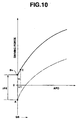
- one dot chain line curve illustrates the variation of ordinary target driving force (tTd#n) when the vehicle operator depresses the vehicle's accelerator pedal from the released position.
- the proposed driving system further includes a driving force correction generator that determines a driving force correction (ADDFD) in response to the running resistance increment (RESTRQ), and a corrected target driving force generator where the driving force correction (ADDFD) is added to the ordinary target driving force (tTd#n) to produce a corrected target driving force driving force (tTd).
- This corrected target driving force (tTd) is used to determine a target engine torque (tTe) and a target CVT ratio (tRATIO).
- the fully drawn curve in Figure 10 or the broken line curve in Figure 5 illustrate the variation of the corrected target driving force (tTd) when the vehicle operator depresses the vehicle's accelerator pedal from the released position under a condition where the running resistance increment (RESTRQ) is large enough to cause the driving force correction generator to provide a substantial amount of driving force correction (ADDFD).
- the engine is adjusted to produce engine torque needed to accomplish the corrected target driving force that has been given after addition of the driving force correction (ADDFD) to the ordinary target driving force (tTd#n). If the driving force correction (ADDFD) is not zero, occurrence of shocks due to a change in engine torque is unavoidable.
- ADDFD driving force correction
- the reference character A represents an operation point when the accelerator pedal is released.
- the driving force correction (ADDFD) is zero so that correction of the ordinary target driving force (tTd#n) is not carried out. If the accelerator pedal is slightly depressed from the released position by an amount ⁇ 1, the driving force correction (ADDFD) becomes greater than zero so that the corrected driving force (tTd) jumps from the operation point A to an operation point B+, and then increases to an operation point C.
- an object of the present invention is to improve the proposed driving force control system such that the corrected target driving force is tamed to avoid occurrence of shocks when a vehicle's accelerator pedal is depressed from its released position.
- a driving force control system for an automotive vehicle powertrain including a prime mover and an automatic transmission, the driving force control system comprising:
- Figure 1 is a schematic view of a passenger automobile installed with a driving force control system implementing the present invention.
- the automobile has a powertrain including a prime mover in the form of an internal combustion engine 101 and an automatic transmission 103, and a powertrain control module (PCM) 50. Output from the engine 101 is transmitted via the automatic transmission 103 to driving wheels.
- the PCM 50 controls engine torque of the engine 101 and a speed ratio, a ratio between a transmission input shaft speed and a transmission output shaft speed, of the automatic transmission 103 in such a manner as to cause the powertrain to produce driving force desired.
- An accelerator pedal position detector in the form of an accelerator pedal opening sensor 105 is operatively connected to a manually operable accelerator, such as for example, an accelerator pedal, to feed operator demand on driving force to the PCM 50.
- the accelerator pedal opening sensor 105 detect an accelerator position and generates an APO signal indicative of the detected accelerator position. This APO signal is fed as an input to the PCM 50.
- the vehicle operator depresses the accelerator pedal to express driving force demand.
- the APO signal is indicative of driving force demand, i.e., operator demand on driving force
- the accelerator pedal opening sensor 105 is a sensor to detect vehicle's operator demand on driving force.
- any other form of sensor may be employed for this purpose.
- the automatic transmission 103 has plurality of ranges that may be selected by a range select lever 107.
- An inhibitor switch 108 is operatively connected to the range select lever 107 to detect which range is being selected and generates a select signal indicative of the range being selected by the select lever 107.
- the select signal is fed as an input to the PCM 50.
- a vehicle speed sensor 11 detects a predetermined parameter indicative of the vehicle speed and generates a vehicle speed signal VSP.
- the vehicle speed sensor 11 may take any form as long as it could output signal indicative of the vehicle speed.
- the vehicle speed signal VSP is fed as an input to the PCM 50.
- a crankshaft angle sensor not shown, generates an engine speed signal NRPM.
- the engine speed signal NRPM is fed as an in put to the PCM 50.
- the PCM 50 Based on input signals including the above-mentioned input signals, the PCM 50 conducts adjustment of engine torque of the engine 101 and adjustment of the ratio within the automatic transmission 103 to produce driving torque transmitted to the driving wheels.
- the adjustment of engine torque may be made by varying one of or any combination of fuel injection quantity Tp, intake air flow rate Qa, and spark timing.
- an electronically controlled throttle valve 102 is disposed in an intake passage of the engine 101.
- a throttle control module TCM adjusts the position of the throttle valve 102.
- the automatic transmission 103 includes a continuously variable transmission (CVT) that can alter a ratio continuously in response to a ratio command from the PCM 50.
- the PCM 50 multiplies a predetermined constant with the vehicle speed VSP to give a transmission output shaft speed No.
- An input shaft speed sensor 12 detects revolution speed of the transmission input shaft and generates an input shaft speed signal Nin indicative of the detected speed of the transmission input shaft.
- the input shaft speed signal Nin is fed as input to the PCM 50.
- the PCM 50 calculates a ratio RATIO Nin/No and determines the ratio command and applies it to a ratio control mechanism of the CVT 103 to match a target ratio tRATIO that is determined by the PCM 50.
- the CVT may be of the V belt type or the toroidal type. Rotation of the output shaft of the automatic transmission 103 is transmitted via a final-drive to the vehicle driving wheels.
- the final-drive has a fixed ratio.
- the PCM 50 is in the form of a microprocessor that includes a CPU, a ROM, a RAM, and an input/output device.
- FIG. 2 is a control block diagram of the driving force control. It includes an ordinary target driving force generator (OTDFG) 1, a running resistance increment generator (RRIG) 2, a preliminary driving force correction generator (PDFCG) 4, a corrected target driving force generator (CTDFG) 6, a target engine torque generator (TETG) 7, and a target ratio generator (TRG) 8. It also includes a limit criteria 3 and a select low switch 5.
- ODFG ordinary target driving force generator
- RRIG running resistance increment generator
- PDFCG preliminary driving force correction generator
- CDFG corrected target driving force generator
- TRG target ratio generator
- It also includes a limit criteria 3 and a select low switch 5.
- the OTDFG 1 inputs APO and VSP.
- the OTDFG 1 includes a memory storing a predetermined tTd#n vs. (APO, VSP) map that defines various target values indicative of ordinary target driving force tTd#n at various values of VSP with various values of APO.
- Each target value tTd#n exhibits ordinary driving force needed to accomplish a desired traveling performance of a vehicle on a flat road having 0 % gradient.
- the OTDFG 1 performs a table look-up operation of the map using APO and VSP to determine an ordinary target driving force tTd#n and provides the determined ordinary target driving force tTd#n to the CTDFG 6.
- tTd#n MAP [APO, VSP]
- the RRIG 2 calculates an increase in running resistance from a standard value of running resistance to give a running resistance increment RESTRQ.
- the running resistance increment RESTRQ is indicative of a value resulting from converting the increment of running resistance force to the increment of resistance torque transmitted to the transmission output shaft.
- the PDFCG 6 inputs RESTRQ and determines a preliminary driving force correction TADDFD.
- the RRIG 2 includes a driving torque generator (DTG) 21, a standard running resistance generator (SRRG) 22, and an acceleration resistance generator (ARG) 23.
- TSG driving torque generator
- SRRG standard running resistance generator
- ARG acceleration resistance generator
- the DTG 21 inputs Tp and NRPM.
- the DTG 21 includes a memory storing a predetermined ENGTRQ vs., (Tp, NRPM) map that defines various values of engine torque to be produced by the engine 101 against various combinations of values of Tp and values of NRPM.
- the DTG 21 performs a table look-up operation of this map using Tp and NRPM to determine an engine torque ENGTRQ. It multiplies the determined ENGTRQ with a current speed ratio RATIO established within the CVT 103 and a torque transmission ratio ⁇ RATIO established within a torque converter to give an driving torque TRQOUT transmitted to the transmission output shaft.
- the SRRG 22 inputs VSP.
- the SRG B22 includes a memory storing a predetermined RLDTRQ vs., VSP map that defines various value of standard running resistance RLDTRQ against various values VSP.
- the standard running resistance RLDTRQ is indicative of a value resulting from converting the standard running resistance force to the resistance torque transmitted to the transmission output shaft.
- RLDTRQ MAP [VSP]
- the ARG 23 inputs vehicle acceleration GDATA [m/s 2 ] that is derived as the first time derivative of VSP or as a measure of an accelerometer. Vehicle weight WV, tire radius rTIRE [m] and inverse of final reduction ratio zRATIO are stored as reference data in the ARG 23.
- the RRIG 20 calculates a sum RLDTRQ and GTRQ and subtracts the sum from TRQOUT to give the running resistance increment RESTRQ.
- the RRIG 20 provides RESTRQ to the PDFCG 4.
- the PDFCG 4 includes a memory storing a predetermined TADDFD vs., RESTRQ map as illustrated by the fully drawn line in Figure 3 and performs a table look-up operation of the stored map using RESTRQ to determine a preliminary driving force correction TADDFD.
- the preliminary driving force correction TADDFD which is expressed in terms of the same dimension [N] as the target value tTd#n, is set less than a value resulting from converting RESTRQ to running resistance force. This relation can be expressed as TADDFD ⁇ RESTRQ/zRATIO/rTIRE
- TADDFD is always less than 100 % of the converted value from RESTRQ.
- the limit criteria 3 include a memory storing a predetermined map as illustrated by the fully drawn line in Figure 4. This map defines values of a driving force correction upper limit ADDFDLM against values of APO. At the limit criteria 3, ADDFDLM is determined which corresponds to APO.
- the limit criteria 3 provide ADDFDLM to the select low switch 5.
- the PDFCG 4 provides TADDFD to the select low switch 5.
- the select low switch 5 outputs a lower one of ADDFDLM and TADDFD as a driving force correction ADDFD.
- the select low switch 5 provides ADDFD to the CTDFG 6.
- the CTDFG 6 adds ADDFD to tTd#n to give a target driving force tTd.
- the CTDFG 6 provides tTd to a target engine torque generator (TETG) 7 and also to a target ratio generator (TRG) 8.
- TETG target engine torque generator
- TRG target ratio generator
- the TETG 7 provides tTe to the engine 101.
- the TCM 51 determines the position of the electronically controlled throttle valve 102, a control section of the engine 101 determines Tp and spark timing.
- the TRG 8 receives VSP as well as tTd and determines a target speed ratio tRATIO using VSP and tTd.
- the TRG 8 has a memory storing a predetermined tRATIO vs., (tTd, VSP) map that defines various values of tRATIO against various combinations of values of VSP and values of tTd. In determining tRATIO, the TRG 8 performs a table look-up operation of this predetermined map using VSP and tTd.
- the TRG 8 provides tRATIO to a ratio control mechanism of the CVT 103. The ratio control mechanism adjusts RATIO within the CVT 103 to tRATIO.
- FIG. 3 illustrates the TADDFD vs., RESTRQ map that is stored in the PDFCG 4.
- TADDFD is set against RESTRQ and used to compensate for a shortage in acceleration.
- TADDFD Over values of RESTRQ not greater than a first predetermined value RES#TLEV1, zero is set as TADDFD.
- TADDFD is zero, thus preventing occurrence of any unexpected driving force correction due to, for example, an error in calculating RESTRQ, a small variation in wind against the vehicle or a small variation in running resistance derived from a gradual gradient change.
- TADDFD 0.5 x RESTRQ/zRATIO/rTIRE
- RESTRQ is divided by zRATIO to give torque on the driving wheel shaft, and this torque is divided by the tire radius rTIRE to convert the dimension from torque [Nm] to force [N], and 50% of the force given by this conversion is set as TADDFD. This percentage is not limited to 50% and may take an appropriate value less than 100 %.
- the remaining portion of RESTRQ left unconverted is not translated into TADDFD, leaving a room for the vehicle operator to participate the driving force correction by depressing the accelerator pedal, thus providing a natural acceleration fit to the vehicle operator's demand.
- TADDFD 0.5 x RESTRQ/zRATIO/rTIRE .
- TADDFD is kept at a predetermined value ADDFDLMmax.
- TADDFD ADDFDLMmax .
- ADDFDLMmax is the maximum value that may be determined at the limit criteria 3 (see Figure 4).
- Figure 4 illustrates an ADDFDLM vs., APO map used at the limit criteria 3.
- ADDFDLM Over values of APO from 0 to a predetermined intermediate value ⁇ , ADDFDLM increases an a predetermined ramp rate as APO increases from 0 to the predetermined value ⁇ .
- the predetermined value ⁇ is 3/8 or 4/8 if the maximum of APO is 8/8.
- the select low switch 5 select a lower one of TADDFD and ADDFDLM to give the result as ADDFD.
- the select low switch 5 provides the ADDFD to the CTDFG 6.
- the ADDFD is added to tTd#n.
- ADDFD gradually increases along the ramp of TADDFD as the accelerator pedal is depressed from the released position. This provides a smooth acceleration without any shock imparted to the vehicle body, resulting in enhancement of drivability.
- the select low switch 5 sets TADDFD as ADDFD. Accordingly, the correction of the tTd#n is made to produce acceleration high enough to meet RESTRQ with good accuracy.
- Figure 6 is a flaw chart of a control routine Implementing the present invention.
- the control routine is stored in the ROM of the microprocessor that forms the PCM 50.
- the CPU inputs VSP, APO, and NRPN.
- the CPU determines tTd#n by performing a table look-up operation, using APO and VSP, of the tTd#n vs., (APO, VSP) map illustrated in Figure 2.
- the controller 3 determines ENGTRQ by performing a table look-up operation, using TP and NRPN, of the ENGTRQ vs., (Tp, NRPM) map illustrated in Figure 2 calculates a product of ENGTRQ, RATIO, and ⁇ RATIO to give TRQOUT.
- the CPU determines RLDTRQ by performing a table look-up operation, using VSP, of the RLDTRQ vs., VSP map illustrated in Figure 2.
- the CPU determines GTRQ after calculating a product of GDATA, WV, rTIRE, and zRATIO.
- the CPU determines RESTRQ after subtracting (RLDTRQ + GTRQ) from TRQOUT.
- the CPU determines TADDFD by performing a table look-up operation, using RESTRQ, of the TADDFD vs., RESTRQ map illustrated in Figure 3.
- the CPU determines ADDFDLM by performing a table look-up operation, using APO, of the ADDFDLM vs., APO map illustrated in Figure 4.
- step S9 the CPU determines whether or not TADDFD ⁇ ADDFDLM. If this is the case, the routine proceeds to step S10. If this is not the case, the routine proceeds to step S11.
- the CPU sets TADDFD as ADDFD.
- the CPU sets ADDFDLM as ADDFD.
- the CPU determines tTd by adding ADDFD to tTd#n.
- the target driving force tTd thus determined as explained above is fed to the TETG 7 and also to TRG 8.
- Figure 7 illustrates a second preferred implementation according to the present invention.
- the second preferred implementation is substantially the same as the first preferred implementation except the provision of a correction rate generator (CRG) 30 and a multiplier 31 instead of the limit criteria 3 and select low switch 5 (see Figure 2).
- CCG correction rate generator
- the CRG 30 determines a correction rate RADDFD against APO.
- RADDFD may take a value falling in a range as follows: 0 ⁇ RADDFD ⁇ 1.
- RADDFD gradually increases from 0 toward 1.
- the multiplier 31 calculates a product of RADDFD and TADDFD to give ADDFD.
- the ADDFD determined by the multiplier 31 is fed to a CTDFG 6.
- the ADDFD is added to tTd#n to give tTd.
- the third preferred implementation is substantially the same as the first or second preferred implementation except the manner of determining RESTRQ.
- mad gradient ⁇ is estimated based on digital road maps.
- a GPS antenna 113 is integrated with a dead reckoning with map matching unit 54 for automobile navigation.
- Digital road maps containing topographical information are stored in an appropriate recording medium, such as, CD-ROM or DVD-ROM, in the unit 54.
- the unit 54 transmits position and topographical information to an environment information processing module (EIPM) 52.
- the EIPM 52 determines road gradient ⁇ based on the position and topographical information and calculates based on the road gradient ⁇ to determine RESTRQ.
- the determined RESTRQ is fed to a PDFCG 4 in a similar manner to Figure 2 or 7.
- Figure 9 is a flow chart of a control routine implementing the present invention to determine RESTRQ.
- the CPU of the EIPM 52 inputs a vehicle's location, mesh numbers MESHNO of nodes of a current enclosed area around the vehicle's location, the vehicle's heading, and an angle ⁇ of direction of travel with respect to an X-axis direction intersecting the vehicle.
- Figure 8 shows a portion of an image of a digital map in which each of enclosed areas is determined by an X-Y grid.
- X-axis extends from west to east, and Y-axis extends from south to north.
- the vehicle's location is within an enclosed square area having four nodes NW, NE, SE, and SW identified by mesh numbers 123568, 123569, 129034, and 129033, respectively.
- the X-Y coordinates of the node points are included in a database along with altitude data at the node points.
- the four nodes NW, NE, SE, and SW have altitude data htNW, htNE, htSE, and htSW, respectively.
- LEN represents a length of each of line segments surrounding one of enclosed areas and interconnecting nodes.
- the CPU inputs altitude data htNW, htNE, htSE, and htSW of the vicinity nodes identified by the mesh numbers MESHNO and stores them at data[MESHNO].
- the target value tTd#n has been expressed in terms of the vehicle driving force.
- This target value tTd#n may be a predetermined parameter indicative of the vehicle driving force. Examples of the predetermined parameter are driving wheel shaft torque and transmission output shaft torque.
- TADDFD and ADDFDLM are expressed in terms of torque on the driving wheel shaft.
- TADDFD and ADDFDLM are expressed in terms of torque on the transmission output shaft.
- both the engine torque and the ratio are controlled based on tTd to accomplish the driving force expressed by tTd.
- the manner of accomplishing tTd is not limited to this example. It is possible to control the engine torque based on tTd and to control the ratio without any reference to tTd.
Landscapes
- Engineering & Computer Science (AREA)
- General Engineering & Computer Science (AREA)
- Mechanical Engineering (AREA)
- Chemical & Material Sciences (AREA)
- Combustion & Propulsion (AREA)
- Automation & Control Theory (AREA)
- Transportation (AREA)
- Control Of Vehicle Engines Or Engines For Specific Uses (AREA)
- Control Of Throttle Valves Provided In The Intake System Or In The Exhaust System (AREA)
- Electrical Control Of Air Or Fuel Supplied To Internal-Combustion Engine (AREA)
- Control Of Driving Devices And Active Controlling Of Vehicle (AREA)
Applications Claiming Priority (2)
| Application Number | Priority Date | Filing Date | Title |
|---|---|---|---|
| JP10369399A JP3767244B2 (ja) | 1999-04-12 | 1999-04-12 | 車両の駆動力制御装置 |
| JP10369399 | 1999-04-12 |
Publications (3)
| Publication Number | Publication Date |
|---|---|
| EP1045121A2 true EP1045121A2 (fr) | 2000-10-18 |
| EP1045121A3 EP1045121A3 (fr) | 2002-01-02 |
| EP1045121B1 EP1045121B1 (fr) | 2009-12-23 |
Family
ID=14360873
Family Applications (1)
| Application Number | Title | Priority Date | Filing Date |
|---|---|---|---|
| EP00107554A Expired - Lifetime EP1045121B1 (fr) | 1999-04-12 | 2000-04-07 | Contrôle d'une force de traction avec une correction dépendante de la puissance commandée par le conducteur |
Country Status (4)
| Country | Link |
|---|---|
| US (1) | US6330504B1 (fr) |
| EP (1) | EP1045121B1 (fr) |
| JP (1) | JP3767244B2 (fr) |
| DE (1) | DE60043556D1 (fr) |
Cited By (10)
| Publication number | Priority date | Publication date | Assignee | Title |
|---|---|---|---|---|
| EP1219490A2 (fr) * | 2000-12-26 | 2002-07-03 | Nissan Motor Co., Ltd. | Système de commande de la force d'entraínement |
| EP1400435A2 (fr) * | 2002-09-18 | 2004-03-24 | Nissan Motor Co., Ltd. | Système d'assistance à la conduite pour véhicule |
| EP1504947A3 (fr) * | 2003-08-08 | 2006-02-15 | Nissan Motor Co., Ltd. | Système d'assistance à la conduite pour un véhicule |
| WO2019121624A1 (fr) * | 2017-12-21 | 2019-06-27 | Renault S.A.S | Procede de determination de la consigne de couple d'un moteur de vehicule automobile |
| FR3089162A1 (fr) | 2018-11-30 | 2020-06-05 | Renault S.A.S | Procédé et système de contrôle continu de l’accélération d’un véhicule automobile hybride |
| US10814877B2 (en) | 2018-03-26 | 2020-10-27 | Hyundai Motor Company | Integrated control method and integrated controller of powertrain |
| CN111873991A (zh) * | 2020-07-22 | 2020-11-03 | 中国第一汽车股份有限公司 | 一种车辆转向的控制方法、装置、终端及存储介质 |
| WO2021089333A1 (fr) | 2019-11-08 | 2021-05-14 | Renault S.A.S | Procédé de commande d'un groupe motopropulseur pour véhicule automobile comprenant au moins deux sources de puissance motrice |
| EP3858692A4 (fr) * | 2018-11-19 | 2021-11-24 | Komatsu Ltd. | Véhicule de travail, dispositif et procédé de commande pour véhicule de travail |
| EP4385843A1 (fr) * | 2022-12-14 | 2024-06-19 | AMPERE s.a.s | Procédé de compensation de forces résistives appliquées à un véhicule |
Families Citing this family (17)
| Publication number | Priority date | Publication date | Assignee | Title |
|---|---|---|---|---|
| US6440038B1 (en) * | 2000-06-01 | 2002-08-27 | Cummins Engine Company, Inc. | Method and system for managing torque of a drivetrain |
| JP3736345B2 (ja) * | 2000-12-22 | 2006-01-18 | 日産自動車株式会社 | 自動車のエンジン制御装置 |
| DE10360641B4 (de) * | 2003-12-23 | 2017-01-12 | Jochen Strenkert | Vorrichtung mit einer Einheit zum Betätigen eines stufenlosen Kraftfahrzeuggetriebes |
| JP4172391B2 (ja) * | 2003-12-24 | 2008-10-29 | 株式会社デンソー | 車両統合制御システムおよびプログラム |
| EP1868058B1 (fr) | 2005-01-18 | 2012-09-05 | Kongsberg Automotive Holding ASA | Mécanisme de rétrogradation forcée de pédale et mécanisme de fixation de pédale |
| US7617893B2 (en) * | 2005-08-02 | 2009-11-17 | Ford Global Technologies, Llc | Method and system for determining final desired wheel power in a hybrid electric vehicle powertrain |
| US7398147B2 (en) * | 2005-08-02 | 2008-07-08 | Ford Global Technologies, Llc | Optimal engine operating power management strategy for a hybrid electric vehicle powertrain |
| US8175779B2 (en) * | 2006-02-23 | 2012-05-08 | Toyota Jidosha Kabushiki Kaisha | Vehicle driving force control apparatus and method |
| US8121767B2 (en) * | 2007-11-02 | 2012-02-21 | GM Global Technology Operations LLC | Predicted and immediate output torque control architecture for a hybrid powertrain system |
| CN102159819A (zh) * | 2008-10-31 | 2011-08-17 | 丰田自动车株式会社 | 车辆的减振控制装置 |
| JP4853565B2 (ja) * | 2009-10-21 | 2012-01-11 | 日産自動車株式会社 | 車両の駆動力制御装置 |
| JP4915445B2 (ja) * | 2009-11-06 | 2012-04-11 | 三菱電機株式会社 | 車両駆動力制御装置 |
| US8560144B2 (en) * | 2011-06-17 | 2013-10-15 | GM Global Technology Operations LLC | Output torque rate limiting based on a request busyness indicator that considers the recent time history of the output torque request |
| FR2995399B1 (fr) * | 2012-09-11 | 2015-05-22 | Renault Sa | Dispositif et procede d'estimation de la charge d'un vehicule automobile |
| DE102013225500A1 (de) * | 2013-12-10 | 2015-06-11 | Robert Bosch Gmbh | Verfahren zur Überwachung eines Antriebs eines Fahrzeug |
| DE102015223504A1 (de) * | 2015-11-27 | 2017-06-01 | Robert Bosch Gmbh | Verfahren und Vorrichtung zum Betreiben eines Kraftfahrzeugs |
| KR101955614B1 (ko) * | 2017-01-19 | 2019-03-08 | (주)에코플러스 | 가속페달을 사용한 차량의 출력제어 시스템 |
Citations (5)
| Publication number | Priority date | Publication date | Assignee | Title |
|---|---|---|---|---|
| JPH0688541A (ja) | 1992-09-08 | 1994-03-29 | Hitachi Ltd | 車両用駆動力制御装置 |
| JPH10266882A (ja) | 1997-03-24 | 1998-10-06 | Nissan Motor Co Ltd | 車両の駆動力制御装置 |
| JPH1158289A (ja) | 1997-08-25 | 1999-03-02 | Fanuc Ltd | ロボット非常停止用デッドマンスイッチ機構並びに教示操作盤 |
| JPH1158291A (ja) | 1997-08-27 | 1999-03-02 | Fuji Elelctrochem Co Ltd | 積層シートの切断方法およびその装置 |
| JPH11103693A (ja) | 1997-10-07 | 1999-04-20 | Suzutec Co Ltd | 土供給装置 |
Family Cites Families (11)
| Publication number | Priority date | Publication date | Assignee | Title |
|---|---|---|---|---|
| JPS61119856A (ja) * | 1984-09-25 | 1986-06-07 | Toyota Motor Corp | 無段変速機を備えた車両の駆動力制御装置 |
| JPH04191132A (ja) * | 1990-11-26 | 1992-07-09 | Mitsubishi Electric Corp | 車両の走行抵抗検出装置 |
| JP2778251B2 (ja) * | 1991-04-02 | 1998-07-23 | 三菱自動車工業株式会社 | 内燃機関と連続可変変速機との制御装置 |
| JP3236344B2 (ja) * | 1992-05-13 | 2001-12-10 | 本田技研工業株式会社 | 車両の動力源出力制御装置 |
| JP3461572B2 (ja) * | 1994-06-09 | 2003-10-27 | 株式会社日立ユニシアオートモティブ | 車両の制御装置 |
| JP3203976B2 (ja) * | 1994-09-05 | 2001-09-04 | 日産自動車株式会社 | 車両用駆動力制御装置 |
| JPH094705A (ja) * | 1995-06-16 | 1997-01-07 | Aisin Aw Co Ltd | 自動変速機の制御装置 |
| KR19980087004A (ko) * | 1997-05-14 | 1998-12-05 | 가나이 쯔도무 | 자동차의 자동 변속기 제어 장치 및 제어 방법 |
| JP3463855B2 (ja) * | 1997-12-18 | 2003-11-05 | 富士重工業株式会社 | 無段変速機の変速制御装置 |
| JPH11294547A (ja) * | 1998-04-07 | 1999-10-29 | Hitachi Ltd | 車両用自動変速の制御装置および制御方法 |
| JP3589073B2 (ja) * | 1999-03-05 | 2004-11-17 | 日産自動車株式会社 | 車両駆動力制御装置 |
-
1999
- 1999-04-12 JP JP10369399A patent/JP3767244B2/ja not_active Expired - Fee Related
-
2000
- 2000-04-07 EP EP00107554A patent/EP1045121B1/fr not_active Expired - Lifetime
- 2000-04-07 DE DE60043556T patent/DE60043556D1/de not_active Expired - Lifetime
- 2000-04-12 US US09/547,884 patent/US6330504B1/en not_active Expired - Lifetime
Patent Citations (5)
| Publication number | Priority date | Publication date | Assignee | Title |
|---|---|---|---|---|
| JPH0688541A (ja) | 1992-09-08 | 1994-03-29 | Hitachi Ltd | 車両用駆動力制御装置 |
| JPH10266882A (ja) | 1997-03-24 | 1998-10-06 | Nissan Motor Co Ltd | 車両の駆動力制御装置 |
| JPH1158289A (ja) | 1997-08-25 | 1999-03-02 | Fanuc Ltd | ロボット非常停止用デッドマンスイッチ機構並びに教示操作盤 |
| JPH1158291A (ja) | 1997-08-27 | 1999-03-02 | Fuji Elelctrochem Co Ltd | 積層シートの切断方法およびその装置 |
| JPH11103693A (ja) | 1997-10-07 | 1999-04-20 | Suzutec Co Ltd | 土供給装置 |
Cited By (18)
| Publication number | Priority date | Publication date | Assignee | Title |
|---|---|---|---|---|
| EP1219490A2 (fr) * | 2000-12-26 | 2002-07-03 | Nissan Motor Co., Ltd. | Système de commande de la force d'entraínement |
| EP1219490A3 (fr) * | 2000-12-26 | 2004-08-25 | Nissan Motor Co., Ltd. | Système de commande de la force d'entraínement |
| EP1400435A2 (fr) * | 2002-09-18 | 2004-03-24 | Nissan Motor Co., Ltd. | Système d'assistance à la conduite pour véhicule |
| EP1400435A3 (fr) * | 2002-09-18 | 2004-04-28 | Nissan Motor Co., Ltd. | Système d'assistance à la conduite pour véhicule |
| US7457694B2 (en) | 2002-09-18 | 2008-11-25 | Nissan Motor Co., Ltd. | Driving assist system for vehicle |
| EP1504947A3 (fr) * | 2003-08-08 | 2006-02-15 | Nissan Motor Co., Ltd. | Système d'assistance à la conduite pour un véhicule |
| US7395138B2 (en) | 2003-08-08 | 2008-07-01 | Nissan Motor Co., Ltd. | Driving assist system for vehicle |
| FR3075735A1 (fr) * | 2017-12-21 | 2019-06-28 | Renault S.A.S | Procede de determination de la consigne de couple d'un moteur de vehicule automobile |
| WO2019121624A1 (fr) * | 2017-12-21 | 2019-06-27 | Renault S.A.S | Procede de determination de la consigne de couple d'un moteur de vehicule automobile |
| US10814877B2 (en) | 2018-03-26 | 2020-10-27 | Hyundai Motor Company | Integrated control method and integrated controller of powertrain |
| EP3858692A4 (fr) * | 2018-11-19 | 2021-11-24 | Komatsu Ltd. | Véhicule de travail, dispositif et procédé de commande pour véhicule de travail |
| FR3089162A1 (fr) | 2018-11-30 | 2020-06-05 | Renault S.A.S | Procédé et système de contrôle continu de l’accélération d’un véhicule automobile hybride |
| WO2021089333A1 (fr) | 2019-11-08 | 2021-05-14 | Renault S.A.S | Procédé de commande d'un groupe motopropulseur pour véhicule automobile comprenant au moins deux sources de puissance motrice |
| FR3102964A1 (fr) | 2019-11-08 | 2021-05-14 | Renault S.A.S | Procédé de commande d’un groupe motopropulseur pour véhicule automobile comprenant au moins deux sources de puissance motrice. |
| CN111873991A (zh) * | 2020-07-22 | 2020-11-03 | 中国第一汽车股份有限公司 | 一种车辆转向的控制方法、装置、终端及存储介质 |
| CN111873991B (zh) * | 2020-07-22 | 2022-04-08 | 中国第一汽车股份有限公司 | 一种车辆转向的控制方法、装置、终端及存储介质 |
| EP4385843A1 (fr) * | 2022-12-14 | 2024-06-19 | AMPERE s.a.s | Procédé de compensation de forces résistives appliquées à un véhicule |
| FR3143507A1 (fr) * | 2022-12-14 | 2024-06-21 | Renault S.A.S | Procédé de compensation de forces résistives appliquées à un véhicule |
Also Published As
| Publication number | Publication date |
|---|---|
| EP1045121B1 (fr) | 2009-12-23 |
| JP2000297662A (ja) | 2000-10-24 |
| DE60043556D1 (de) | 2010-02-04 |
| JP3767244B2 (ja) | 2006-04-19 |
| US6330504B1 (en) | 2001-12-11 |
| EP1045121A3 (fr) | 2002-01-02 |
Similar Documents
| Publication | Publication Date | Title |
|---|---|---|
| US6330504B1 (en) | Vehicle driving force control with operator power demand responsive correction | |
| EP2467288B1 (fr) | Système contrôle véhicule | |
| US6389347B1 (en) | Vehicle driving force control with different corrections for engine torque control an CVT ratio control | |
| US7011602B2 (en) | Shift control for continuously-variable transmission | |
| US6679807B2 (en) | Vehicle driving control device and method | |
| RU2505432C2 (ru) | Система управления транспортного средства | |
| US9630610B2 (en) | Driving force control system for vehicle | |
| US8909386B2 (en) | Vehicle control system | |
| US5507705A (en) | Vehicle control device | |
| US8301351B2 (en) | Gear shift system for vehicle, control method and control device for automatic transmission | |
| WO2018207870A1 (fr) | Dispositif de commande de véhicule | |
| US6306062B1 (en) | Driving force control with gradient resistance torque dependent correction factor | |
| JP4531876B2 (ja) | 車輌の変速制御装置 | |
| US6599220B2 (en) | Control of infinitely variable transmission | |
| US6345222B1 (en) | Vehicle driving force control with differential dependent correction | |
| JPH09229173A (ja) | 自動変速機制御装置 | |
| EP1034961B1 (fr) | Système de régulation de la force motrice dans un véhicule | |
| EP1548314A2 (fr) | Dispositif et méthode de commande de transmission de couple | |
| JP4697990B2 (ja) | 車輌の変速制御装置 | |
| US6418367B1 (en) | Engine transmission control system | |
| JPH05263904A (ja) | 自動車とその動力制御方法及び装置 | |
| JPH06193723A (ja) | 車両用自動変速制御装置 | |
| JP4206256B2 (ja) | 無段変速機の変速制御装置 | |
| JP4531878B2 (ja) | 車輌の変速制御装置 | |
| WO2018207869A1 (fr) | Dispositif de commande de véhicule |
Legal Events
| Date | Code | Title | Description |
|---|---|---|---|
| PUAI | Public reference made under article 153(3) epc to a published international application that has entered the european phase |
Free format text: ORIGINAL CODE: 0009012 |
|
| 17P | Request for examination filed |
Effective date: 20000407 |
|
| AK | Designated contracting states |
Kind code of ref document: A2 Designated state(s): AT BE CH CY DE DK ES FI FR GB GR IE IT LI LU MC NL PT SE Kind code of ref document: A2 Designated state(s): DE GB |
|
| AX | Request for extension of the european patent |
Free format text: AL;LT;LV;MK;RO;SI |
|
| PUAL | Search report despatched |
Free format text: ORIGINAL CODE: 0009013 |
|
| AK | Designated contracting states |
Kind code of ref document: A3 Designated state(s): AT BE CH CY DE DK ES FI FR GB GR IE IT LI LU MC NL PT SE |
|
| AX | Request for extension of the european patent |
Free format text: AL;LT;LV;MK;RO;SI |
|
| RIC1 | Information provided on ipc code assigned before grant |
Free format text: 7F 02D 29/02 A, 7F 02D 41/04 B, 7F 02D 41/14 B, 7F 02D 41/02 B, 7B 60K 41/04 B, 7B 60K 41/14 B, 7F 02D 11/10 B |
|
| AKX | Designation fees paid |
Free format text: DE GB |
|
| 17Q | First examination report despatched |
Effective date: 20070731 |
|
| RIC1 | Information provided on ipc code assigned before grant |
Ipc: B60W 30/18 20060101AFI20090429BHEP Ipc: B60W 10/06 20060101ALN20090429BHEP Ipc: B60W 10/10 20060101ALN20090429BHEP |
|
| GRAP | Despatch of communication of intention to grant a patent |
Free format text: ORIGINAL CODE: EPIDOSNIGR1 |
|
| GRAS | Grant fee paid |
Free format text: ORIGINAL CODE: EPIDOSNIGR3 |
|
| GRAA | (expected) grant |
Free format text: ORIGINAL CODE: 0009210 |
|
| AK | Designated contracting states |
Kind code of ref document: B1 Designated state(s): DE GB |
|
| REG | Reference to a national code |
Ref country code: GB Ref legal event code: FG4D |
|
| REF | Corresponds to: |
Ref document number: 60043556 Country of ref document: DE Date of ref document: 20100204 Kind code of ref document: P |
|
| PLBE | No opposition filed within time limit |
Free format text: ORIGINAL CODE: 0009261 |
|
| STAA | Information on the status of an ep patent application or granted ep patent |
Free format text: STATUS: NO OPPOSITION FILED WITHIN TIME LIMIT |
|
| 26N | No opposition filed |
Effective date: 20100924 |
|
| PGFP | Annual fee paid to national office [announced via postgrant information from national office to epo] |
Ref country code: GB Payment date: 20140402 Year of fee payment: 15 |
|
| PGFP | Annual fee paid to national office [announced via postgrant information from national office to epo] |
Ref country code: DE Payment date: 20140430 Year of fee payment: 15 |
|
| REG | Reference to a national code |
Ref country code: DE Ref legal event code: R119 Ref document number: 60043556 Country of ref document: DE |
|
| GBPC | Gb: european patent ceased through non-payment of renewal fee |
Effective date: 20150407 |
|
| PG25 | Lapsed in a contracting state [announced via postgrant information from national office to epo] |
Ref country code: DE Free format text: LAPSE BECAUSE OF NON-PAYMENT OF DUE FEES Effective date: 20151103 Ref country code: GB Free format text: LAPSE BECAUSE OF NON-PAYMENT OF DUE FEES Effective date: 20150407 |