EP1044477B1 - Alkaline cell having a cathode incorporating expanded graphite - Google Patents
Alkaline cell having a cathode incorporating expanded graphite Download PDFInfo
- Publication number
- EP1044477B1 EP1044477B1 EP99902069A EP99902069A EP1044477B1 EP 1044477 B1 EP1044477 B1 EP 1044477B1 EP 99902069 A EP99902069 A EP 99902069A EP 99902069 A EP99902069 A EP 99902069A EP 1044477 B1 EP1044477 B1 EP 1044477B1
- Authority
- EP
- European Patent Office
- Prior art keywords
- expanded graphite
- graphite
- cathode
- electrochemical cell
- cell according
- Prior art date
- Legal status (The legal status is an assumption and is not a legal conclusion. Google has not performed a legal analysis and makes no representation as to the accuracy of the status listed.)
- Expired - Lifetime
Links
- OKTJSMMVPCPJKN-UHFFFAOYSA-N Carbon Chemical compound [C] OKTJSMMVPCPJKN-UHFFFAOYSA-N 0.000 title claims abstract description 249
- 229910002804 graphite Inorganic materials 0.000 title claims abstract description 236
- 239000010439 graphite Substances 0.000 title claims abstract description 235
- 239000002245 particle Substances 0.000 claims abstract description 95
- 239000003350 kerosene Substances 0.000 claims abstract description 21
- 238000010521 absorption reaction Methods 0.000 claims abstract description 19
- 239000003575 carbonaceous material Substances 0.000 claims abstract description 5
- NUJOXMJBOLGQSY-UHFFFAOYSA-N manganese dioxide Chemical compound O=[Mn]=O NUJOXMJBOLGQSY-UHFFFAOYSA-N 0.000 claims description 86
- 239000012535 impurity Substances 0.000 claims description 12
- 229910052799 carbon Inorganic materials 0.000 claims description 10
- 239000011149 active material Substances 0.000 claims description 9
- 229910021382 natural graphite Inorganic materials 0.000 claims description 7
- XEEYBQQBJWHFJM-UHFFFAOYSA-N Iron Chemical compound [Fe] XEEYBQQBJWHFJM-UHFFFAOYSA-N 0.000 claims description 5
- 239000011651 chromium Substances 0.000 claims description 4
- 239000010949 copper Substances 0.000 claims description 4
- 239000011135 tin Substances 0.000 claims description 4
- VYZAMTAEIAYCRO-UHFFFAOYSA-N Chromium Chemical compound [Cr] VYZAMTAEIAYCRO-UHFFFAOYSA-N 0.000 claims description 3
- RYGMFSIKBFXOCR-UHFFFAOYSA-N Copper Chemical compound [Cu] RYGMFSIKBFXOCR-UHFFFAOYSA-N 0.000 claims description 3
- ZOKXTWBITQBERF-UHFFFAOYSA-N Molybdenum Chemical compound [Mo] ZOKXTWBITQBERF-UHFFFAOYSA-N 0.000 claims description 3
- ATJFFYVFTNAWJD-UHFFFAOYSA-N Tin Chemical compound [Sn] ATJFFYVFTNAWJD-UHFFFAOYSA-N 0.000 claims description 3
- 229910052787 antimony Inorganic materials 0.000 claims description 3
- WATWJIUSRGPENY-UHFFFAOYSA-N antimony atom Chemical compound [Sb] WATWJIUSRGPENY-UHFFFAOYSA-N 0.000 claims description 3
- 229910052785 arsenic Inorganic materials 0.000 claims description 3
- RQNWIZPPADIBDY-UHFFFAOYSA-N arsenic atom Chemical compound [As] RQNWIZPPADIBDY-UHFFFAOYSA-N 0.000 claims description 3
- 229910052804 chromium Inorganic materials 0.000 claims description 3
- 229910052802 copper Inorganic materials 0.000 claims description 3
- 229910052750 molybdenum Inorganic materials 0.000 claims description 3
- 239000011733 molybdenum Substances 0.000 claims description 3
- 229910052718 tin Inorganic materials 0.000 claims description 3
- 229910052742 iron Inorganic materials 0.000 claims description 2
- 229910052720 vanadium Inorganic materials 0.000 claims description 2
- LEONUFNNVUYDNQ-UHFFFAOYSA-N vanadium atom Chemical compound [V] LEONUFNNVUYDNQ-UHFFFAOYSA-N 0.000 claims description 2
- 230000004580 weight loss Effects 0.000 claims 1
- 238000000034 method Methods 0.000 abstract description 37
- 239000000203 mixture Substances 0.000 description 19
- 229910000831 Steel Inorganic materials 0.000 description 18
- 239000010959 steel Substances 0.000 description 18
- 239000002253 acid Substances 0.000 description 14
- 230000008569 process Effects 0.000 description 13
- 238000010438 heat treatment Methods 0.000 description 12
- 238000005259 measurement Methods 0.000 description 10
- 239000006182 cathode active material Substances 0.000 description 8
- 239000003792 electrolyte Substances 0.000 description 8
- 238000003801 milling Methods 0.000 description 7
- 238000012360 testing method Methods 0.000 description 7
- 239000004020 conductor Substances 0.000 description 6
- 239000000463 material Substances 0.000 description 6
- 230000009467 reduction Effects 0.000 description 6
- 239000000243 solution Substances 0.000 description 6
- KWYUFKZDYYNOTN-UHFFFAOYSA-M Potassium hydroxide Chemical compound [OH-].[K+] KWYUFKZDYYNOTN-UHFFFAOYSA-M 0.000 description 5
- 239000000654 additive Substances 0.000 description 5
- 230000001965 increasing effect Effects 0.000 description 5
- 239000011159 matrix material Substances 0.000 description 5
- 238000000465 moulding Methods 0.000 description 5
- 239000008188 pellet Substances 0.000 description 5
- 239000007858 starting material Substances 0.000 description 5
- QAOWNCQODCNURD-UHFFFAOYSA-N Sulfuric acid Chemical compound OS(O)(=O)=O QAOWNCQODCNURD-UHFFFAOYSA-N 0.000 description 4
- 238000009830 intercalation Methods 0.000 description 4
- 238000002156 mixing Methods 0.000 description 4
- MFOUDYKPLGXPGO-UHFFFAOYSA-N propachlor Chemical compound ClCC(=O)N(C(C)C)C1=CC=CC=C1 MFOUDYKPLGXPGO-UHFFFAOYSA-N 0.000 description 4
- 238000012956 testing procedure Methods 0.000 description 4
- 238000007669 thermal treatment Methods 0.000 description 4
- PXHVJJICTQNCMI-UHFFFAOYSA-N Nickel Chemical compound [Ni] PXHVJJICTQNCMI-UHFFFAOYSA-N 0.000 description 3
- GRYLNZFGIOXLOG-UHFFFAOYSA-N Nitric acid Chemical compound O[N+]([O-])=O GRYLNZFGIOXLOG-UHFFFAOYSA-N 0.000 description 3
- 238000010306 acid treatment Methods 0.000 description 3
- 238000009826 distribution Methods 0.000 description 3
- 239000007770 graphite material Substances 0.000 description 3
- 230000002687 intercalation Effects 0.000 description 3
- 229910017604 nitric acid Inorganic materials 0.000 description 3
- 238000012856 packing Methods 0.000 description 3
- 238000002791 soaking Methods 0.000 description 3
- 239000000126 substance Substances 0.000 description 3
- 239000001117 sulphuric acid Substances 0.000 description 3
- 235000011149 sulphuric acid Nutrition 0.000 description 3
- MHAJPDPJQMAIIY-UHFFFAOYSA-N Hydrogen peroxide Chemical compound OO MHAJPDPJQMAIIY-UHFFFAOYSA-N 0.000 description 2
- 239000004677 Nylon Substances 0.000 description 2
- 238000002441 X-ray diffraction Methods 0.000 description 2
- HCHKCACWOHOZIP-UHFFFAOYSA-N Zinc Chemical compound [Zn] HCHKCACWOHOZIP-UHFFFAOYSA-N 0.000 description 2
- 239000006230 acetylene black Substances 0.000 description 2
- 230000009471 action Effects 0.000 description 2
- 230000000996 additive effect Effects 0.000 description 2
- 238000013019 agitation Methods 0.000 description 2
- 238000013459 approach Methods 0.000 description 2
- 229910021383 artificial graphite Inorganic materials 0.000 description 2
- 239000011230 binding agent Substances 0.000 description 2
- 239000011575 calcium Substances 0.000 description 2
- 239000013078 crystal Substances 0.000 description 2
- 239000008367 deionised water Substances 0.000 description 2
- 238000010586 diagram Methods 0.000 description 2
- 230000009977 dual effect Effects 0.000 description 2
- 239000012530 fluid Substances 0.000 description 2
- 239000007789 gas Substances 0.000 description 2
- 238000000227 grinding Methods 0.000 description 2
- 238000010348 incorporation Methods 0.000 description 2
- 238000004519 manufacturing process Methods 0.000 description 2
- 229920001778 nylon Polymers 0.000 description 2
- 239000000843 powder Substances 0.000 description 2
- 239000012085 test solution Substances 0.000 description 2
- 229910001369 Brass Inorganic materials 0.000 description 1
- OYPRJOBELJOOCE-UHFFFAOYSA-N Calcium Chemical compound [Ca] OYPRJOBELJOOCE-UHFFFAOYSA-N 0.000 description 1
- UFHFLCQGNIYNRP-UHFFFAOYSA-N Hydrogen Chemical compound [H][H] UFHFLCQGNIYNRP-UHFFFAOYSA-N 0.000 description 1
- XUIMIQQOPSSXEZ-UHFFFAOYSA-N Silicon Chemical compound [Si] XUIMIQQOPSSXEZ-UHFFFAOYSA-N 0.000 description 1
- NINIDFKCEFEMDL-UHFFFAOYSA-N Sulfur Chemical compound [S] NINIDFKCEFEMDL-UHFFFAOYSA-N 0.000 description 1
- 239000005864 Sulphur Substances 0.000 description 1
- 239000004480 active ingredient Substances 0.000 description 1
- 239000004411 aluminium Substances 0.000 description 1
- XAGFODPZIPBFFR-UHFFFAOYSA-N aluminium Chemical compound [Al] XAGFODPZIPBFFR-UHFFFAOYSA-N 0.000 description 1
- 229910052782 aluminium Inorganic materials 0.000 description 1
- 235000019270 ammonium chloride Nutrition 0.000 description 1
- 238000004458 analytical method Methods 0.000 description 1
- 239000006183 anode active material Substances 0.000 description 1
- 230000000712 assembly Effects 0.000 description 1
- 238000000429 assembly Methods 0.000 description 1
- 230000008901 benefit Effects 0.000 description 1
- 230000015572 biosynthetic process Effects 0.000 description 1
- 239000010951 brass Substances 0.000 description 1
- 229910052791 calcium Inorganic materials 0.000 description 1
- 238000004364 calculation method Methods 0.000 description 1
- KRVSOGSZCMJSLX-UHFFFAOYSA-L chromic acid Substances O[Cr](O)(=O)=O KRVSOGSZCMJSLX-UHFFFAOYSA-L 0.000 description 1
- 239000011248 coating agent Substances 0.000 description 1
- 238000000576 coating method Methods 0.000 description 1
- 239000010941 cobalt Substances 0.000 description 1
- 229910017052 cobalt Inorganic materials 0.000 description 1
- GUTLYIVDDKVIGB-UHFFFAOYSA-N cobalt atom Chemical compound [Co] GUTLYIVDDKVIGB-UHFFFAOYSA-N 0.000 description 1
- 150000001875 compounds Chemical class 0.000 description 1
- 239000002482 conductive additive Substances 0.000 description 1
- 239000006258 conductive agent Substances 0.000 description 1
- 230000003247 decreasing effect Effects 0.000 description 1
- 238000013461 design Methods 0.000 description 1
- 125000000118 dimethyl group Chemical group [H]C([H])([H])* 0.000 description 1
- 238000010292 electrical insulation Methods 0.000 description 1
- 238000004299 exfoliation Methods 0.000 description 1
- 238000011049 filling Methods 0.000 description 1
- 238000005188 flotation Methods 0.000 description 1
- -1 for example Chemical compound 0.000 description 1
- AWJWCTOOIBYHON-UHFFFAOYSA-N furo[3,4-b]pyrazine-5,7-dione Chemical compound C1=CN=C2C(=O)OC(=O)C2=N1 AWJWCTOOIBYHON-UHFFFAOYSA-N 0.000 description 1
- 239000003349 gelling agent Substances 0.000 description 1
- 229910052739 hydrogen Inorganic materials 0.000 description 1
- 239000001257 hydrogen Substances 0.000 description 1
- 230000003116 impacting effect Effects 0.000 description 1
- 238000005470 impregnation Methods 0.000 description 1
- 230000006698 induction Effects 0.000 description 1
- 230000001939 inductive effect Effects 0.000 description 1
- 238000013101 initial test Methods 0.000 description 1
- 229910052500 inorganic mineral Inorganic materials 0.000 description 1
- 238000011068 loading method Methods 0.000 description 1
- 230000014759 maintenance of location Effects 0.000 description 1
- 238000013508 migration Methods 0.000 description 1
- 230000005012 migration Effects 0.000 description 1
- 239000011707 mineral Substances 0.000 description 1
- 229910052759 nickel Inorganic materials 0.000 description 1
- 239000004745 nonwoven fabric Substances 0.000 description 1
- 239000007800 oxidant agent Substances 0.000 description 1
- 230000003647 oxidation Effects 0.000 description 1
- 238000007254 oxidation reaction Methods 0.000 description 1
- 230000001590 oxidative effect Effects 0.000 description 1
- 239000011236 particulate material Substances 0.000 description 1
- 230000002093 peripheral effect Effects 0.000 description 1
- 239000002985 plastic film Substances 0.000 description 1
- 229920006255 plastic film Polymers 0.000 description 1
- 239000012254 powdered material Substances 0.000 description 1
- 238000004886 process control Methods 0.000 description 1
- 238000000746 purification Methods 0.000 description 1
- 125000001453 quaternary ammonium group Chemical group 0.000 description 1
- 238000005070 sampling Methods 0.000 description 1
- 229910052710 silicon Inorganic materials 0.000 description 1
- 239000010703 silicon Substances 0.000 description 1
- 239000007787 solid Substances 0.000 description 1
- 239000004094 surface-active agent Substances 0.000 description 1
- 238000010998 test method Methods 0.000 description 1
- GPPXJZIENCGNKB-UHFFFAOYSA-N vanadium Chemical compound [V]#[V] GPPXJZIENCGNKB-UHFFFAOYSA-N 0.000 description 1
- 239000002699 waste material Substances 0.000 description 1
- XLYOFNOQVPJJNP-UHFFFAOYSA-N water Substances O XLYOFNOQVPJJNP-UHFFFAOYSA-N 0.000 description 1
- 238000005303 weighing Methods 0.000 description 1
- 238000009736 wetting Methods 0.000 description 1
- 210000000707 wrist Anatomy 0.000 description 1
Images


Classifications
-
- H—ELECTRICITY
- H01—ELECTRIC ELEMENTS
- H01M—PROCESSES OR MEANS, e.g. BATTERIES, FOR THE DIRECT CONVERSION OF CHEMICAL ENERGY INTO ELECTRICAL ENERGY
- H01M4/00—Electrodes
- H01M4/02—Electrodes composed of, or comprising, active material
- H01M4/62—Selection of inactive substances as ingredients for active masses, e.g. binders, fillers
- H01M4/624—Electric conductive fillers
- H01M4/625—Carbon or graphite
-
- C—CHEMISTRY; METALLURGY
- C01—INORGANIC CHEMISTRY
- C01B—NON-METALLIC ELEMENTS; COMPOUNDS THEREOF; METALLOIDS OR COMPOUNDS THEREOF NOT COVERED BY SUBCLASS C01C
- C01B32/00—Carbon; Compounds thereof
- C01B32/20—Graphite
- C01B32/21—After-treatment
- C01B32/22—Intercalation
- C01B32/225—Expansion; Exfoliation
-
- Y—GENERAL TAGGING OF NEW TECHNOLOGICAL DEVELOPMENTS; GENERAL TAGGING OF CROSS-SECTIONAL TECHNOLOGIES SPANNING OVER SEVERAL SECTIONS OF THE IPC; TECHNICAL SUBJECTS COVERED BY FORMER USPC CROSS-REFERENCE ART COLLECTIONS [XRACs] AND DIGESTS
- Y02—TECHNOLOGIES OR APPLICATIONS FOR MITIGATION OR ADAPTATION AGAINST CLIMATE CHANGE
- Y02E—REDUCTION OF GREENHOUSE GAS [GHG] EMISSIONS, RELATED TO ENERGY GENERATION, TRANSMISSION OR DISTRIBUTION
- Y02E60/00—Enabling technologies; Technologies with a potential or indirect contribution to GHG emissions mitigation
- Y02E60/10—Energy storage using batteries
Definitions
- the present invention relates to electrochemical cells, particularly alkaline electrochemical cells, having cathodes formed of a mixture of manganese dioxide together with a conductive carbon material for forming a conductive matrix.
- Typical alkaline electrochemical cells have a cylindrical steel can, with a cathode containing manganese dioxide as active material formed on the interior surface of the steel can.
- An anode having zinc powder and binding agent is dispensed in the central portion of the cell.
- a separator is located between the anode and the cathode, and an alkaline electrolyte contacts the anode, cathode, and separator.
- a conductive anode current collector is generally inserted in the anode active material, and a cover and seal assembly closes the open end of the steel can.
- the cathode is configured as the positive electrode, while the anode is configured as the negative electrode.
- the cathode typically comprises a mixture of electrolytic manganese dioxide particles as the cathode active material, graphite as the electroconductive material, potassium hydroxide solution, and deionised water.
- the conductive graphite is added to enhance the electrical conductivity between the manganese dioxide particles and also to enhance electrical conductivity between the steel can and the cathode active material, as the manganese dioxide has an extremely low specific conductivity.
- the conductive graphite provides an electroconductive matrix throughout the active manganese dioxide particles as well as with the steel can.
- a primary goal in designing alkaline cells is to increase the service performance of the cell.
- the service performance is the length of time taken for the cell to discharge, under a given load, to a specified voltage at which the cell is no longer considered useful for its intended purpose.
- One approach taken to increase service performance has been to increase the internal volume of the cell, in order to increase the amount of active materials that may be employed within the cell.
- the external size of the cell is generally fixed by commercial constraints, thereby limiting the ability to increase the amount of active materials within a particular size cell.
- a higher content of graphite mixed with cathode active material can enhance the electrically conductive properties of the cathode.
- a larger amount of graphite necessarily also consumes a larger volume which, in turn, causes a reduction in the amount of the manganese dioxide active material that can be used in the cathode, thereby leading to a reduction in the discharge capacity of the battery.
- a decrease in the amount of graphite allows an increase in the amount of active manganese dioxide that can be used, but can lead to an increase in the internal resistance of the cathode, thereby decreasing the cell's discharge performance. Accordingly, it is necessary to achieve a suitable compromise between the proportion of conductive material and manganese dioxide active material contained within the cathode of the cell.
- conventional conductive additives employed in the cathode of the cell include high levels of impurities, leading to increased gassing. Excessive gassing of hydrogen is well known to decrease the performance of the cell. Accordingly, it is desirable to minimise the amount of gassing in the cell. Despite past increases in service performance with such additives, the need to find new ways to increase service performance remains the primary goal of cell designers.
- Expanded graphite having an average particle size of 0.5 to 15 ⁇ m has been disclosed in US-A-5,482,798 as being advantageously incorporated into alkaline cells having a manganese dioxide cathode.
- the present invention provides an electrochemical cell comprising a positive electrode having an active material and an electrically conductive carbon material including expanded graphite particles, characterised in that the expanded carbon particles have a kerosene absorption value in the range of 2.7 to 3.1 ml/g.
- a cathode for an electrochemical cell comprising an active cathode material, such as electrolytic manganese dioxide, combined with an electrically conductive carbon, comprising expanded graphite particles, for providing a conductive matrix which occupies low volume, the expanded graphite particles having a kerosene absorption in the range of 2.7 to 3.1 ml/g.
- the cathode of the present invention is particularly adapted for use in electrochemical cells having an alkaline electrolyte.
- the cathode of the electrochemical cell includes an active cathode material, such as electrolytic manganese dioxide, combined with an electrically conductive carbon comprising expanded graphite particles for providing a conductive matrix occupying a low volume.
- the expanded graphite particles preferably have an average surface area-to-mass ratio of at least 18 m 2 /g, an average particle size in the range of 17 to 32 ⁇ m, and a kerosene absorption in the range of 2.7 to 3.1 ml/g.
- the cathode of the present invention is particularly adapted for use in electrochemical cells having an alkaline electrolyte.
- the cells of the present invention employ expanded graphite having certain characteristics.
- the graphite is expanded and graded in order to achieve a desired end result, which appears to be characterised by a cup-shaped, rather than flat, particle.
- Such particles seem better able to contact the manganese dioxide of the electrode, thereby providing better conductivity which, accordingly, allows the amount of graphite required to be reduced.
- the resulting volume can then be occupied by active material instead, thereby increasing performance and service life.
- the graphite of the present invention has certain physical characteristics. Provided that certain characteristics are present, then the graphite is useful. These characteristics do not necessarily define the graphite, but are properties thereof. In particular, the kerosene absorption test has not previously been applied to graphite, but it has now been found that suitable graphite generally has a kerosene absorption of 2.7 to 3.1 ml/g.
- d 50 average particle size
- d 90 particle size surface area to mass ratio
- tap density tap density
- Scott density Scott density
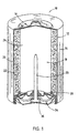
- Alkaline cell 10 includes a steel can 12 having a cylindrical shape and one open end.
- a metallised, plastic film label 14 is formed about the exterior surface of steel can 12 except for the ends of steel can 12.
- At the closed end of steel can 12 is a positive cover 16 preferably formed of plated steel.
- Film label 14 is formed over the peripheral edge of positive cover 16.
- a cathode 20 preferably formed of a mixture of manganese dioxide, graphite, 45% potassium hydroxide (KOH) solution, deionised water, and a conductive can coating, is formed about the interior side surface of the steel can 12. Additionally, an optional binder may be added to the cathode mixture 20.
- An electrolyte 24 formed of potassium hydroxide is disposed within the interior of the separator 22.
- a nylon seal 30 is formed at the open end of steel can 12 to prevent leakage of the active ingredients contained in the steel can 12.
- a negative cover 36 which is preferably formed of plated steel, is disposed in contact with the current collector 26. The negative cover 36 is electrically insulated from the steel can 12 by the nylon seal 30.
- the cathode 20 of the present invention contains an active cathode material, such as electrolytic manganese dioxide (EMD).
- EMD electrolytic manganese dioxide
- the cathode 20 further contains a conductive carbon material, referred to herein as expanded graphite, to provide a conductive matrix within the cathode 20 between the manganese dioxide particles as well as between the manganese dioxide and the steel can to provide for enhanced service performance of the electrochemical cell 10.
- the cathode 20 of the present invention preferably employs electrolytic manganese dioxide (EMD) particles as the active cathode material.
- Electrolytic manganese dioxide has a relatively low specific conductivity and, therefore, a conductive material is typically added with the electrolytic manganese dioxide particles to the cathode 20.
- a conductive material is added to the electrolytic manganese dioxide in an amount that allows for lower cathode resistance and which enhances the electrical conductivity within the cathode 20, and allows for a greater amount of manganese dioxide which increases the service performance of the cell.
- expanded graphite particles are added to the cathode 20 as conductive material.
- expanded graphite is graphite in which the crystal lattice has been expanded.
- methods for expanding graphite including, for example, incorporation of acid/oxidant, followed by thermal treatment.
- Expanded graphite can be added as the electrically conductive material in an amount less than that normally required for conventional graphite, but which yet provides adequate conductivity and cathode mouldability, thereby increasing overall cell performance, especially under high discharge rate applications.
- the use of expanded graphite in the alkaline cell cathode 20 provides a much lower overall bulk cathode resistivity as compared to conventional carbon which includes a crystalline graphite. Expanded graphite further allows for the use of a greater amount of electrolytic manganese dioxide within the generally predefined volume of the cathode 20 of the alkaline cell 10.
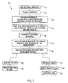
- the expanded graphite additive preferably includes a natural graphite that is first chemically treated and then heated so that it expands in size as described by the following process.
- a natural graphite which is typically mined from the earth pursuant to step 42, is purified to a high purity level in step 44.
- the purification process may include a thermal treatment process as disclosed in US-A-3,807,961 (Markel), or by other techniques, such as successive flotations and chemical treatment.
- the high purity graphite is preferably soaked in sulphuric acid and nitric acid until each of its graphite layers have been acid soaked therein.
- hydrogen peroxide and chromic acid may be used in the acid treatment of the graphite.
- the graphite is ready for heat treatment, as provided in step 48.
- the degree of expansion of the graphite layers may be controlled by careful time and temperature control.
- the heating process preferably involves quickly placing the acid-treated graphite material into a furnace at approximately 1000°C for an approximate time period of two to ten minutes, until the graphite expands in size and de-laminates.
- An oven temperature in the range of 850°C to 1100°C is suitable for the heat treatment. This heat treatment process expands the graphite to approximately three hundred times its original thickness and provides a wrinkled, wavy surface.
- the resulting expanded graphite layers are typically much thinner than the conventional, non-expanded, crystalline graphite layers.
- the expanded graphite is compacted, as provided in step 50.
- the compacted expanded graphite may also be washed and dried at this point.
- the compacted expanded graphite undergoes a milling process, using a jet mill. It is preferred that the milled expanded graphite has an average particle size in the range of seventeen to thirty-two ⁇ m (17-32 ⁇ m), as provided in step 52.
- the average particle size is referred to as the d 50 mean average particle size, which can be measured with a Microtrac full range analyser.
- the expanded graphite may then be premixed with manganese dioxide and other additives to form the cathode 20 of cell 10, as provided in step 54.
- the cathode mix is preferably disposed in the steel can of cell 10, and cell 10 is preferably assembled according to known impact or ring moulding techniques.
- step 55 in which the cathode mix is added to the can.
- the cathode mix is then impact moulded via step 56 in accordance with known impact moulding techniques.
- This generally includes packing the cathode mix with the use of a cylindrical ram rod forcibly actuated through the longitudinal axis of the can. This may include either adding the entire mix and subsequently impacting the cathode mix with the ram rod, or sequentially adding some mix and thereafter packing with the ram rod. In any event, the ram rod forms an anode cavity centrally located within the cathode mix.
- step 57 in which the cathode mix is moulded into rings.
- the process of forming ring moulded cathodes generally includes adding a measured charge of cathode mix to a ring-shaped die set and, with the use of a die press, moulding the cathode mix into the shape of a ring.
- the process of forming and inserting moulded cathode rings into a cell can is widely known in the art.
- step 58 one or more ring moulded cathode rings are inserted into the steel can.
- cathode rings This may be accomplished by loading a fixed number of one or more cathode rings onto a mandrel, which is then lowered into the can and the cathode rings are pressed into the can by way of an upper punch.
- the number of cathode rings inserted into a particular cell may vary depending on the size of the cell. For example, for AAA- and AAAA-type alkaline cells, three or four cathode moulded rings may be adequate to form the cathode of each cell.
- the cathode rings are compressed together in step 59, so that the rings are compactly fit, stacked one on top of the other, and located about the inner wall of the can.
- a process of producing an expanded, highly lamellar graphite product for use in the present invention is described in more detail as follows.
- the process requires the provision of a suitable starting material of lamellar graphite; the intercalation of the starting material with a graphite intercalation compound (GIC); the expansion of the GIC to obtain thermally expanded graphite; and air milling the thermally expanded graphite to obtain a de-laminated, exfoliated graphite product having a high degree of uniformity in particle size, a high bulk volume, and a high surface area to mass ratio.
- GIC graphite intercalation compound
- the starting material is preferably natural mineral flake graphite or synthetic graphite having a degree of three dimensional ordering, i.e ., highly oriented pyrolytic graphite ("HOPG").
- the degree of three dimensional ordering of the graphite can be quantified by x-ray diffraction ("XRD").
- the XRD parameter generally used is referred to as L a and, based on XRD analysis, the graphite best suited for the inventive process has L a values in excess of 2.000 ⁇ (0.2000 nm) and preferably higher.
- the starting material is natural flake graphite, generally as mined in Mozambique, that is processed to a minimum level of purity of 99.9 LOI (loss on ignition), with the particle size of the graphite being between about -20 mesh and +60 mesh and, preferably between about 30 mesh and 70 mesh (200 - 600 ⁇ m).
- LOI loss on ignition
- Such a natural flake graphite can be obtained from the Superior Graphite Co. of Chicago, Illinois, as 2901 grade graphite.
- the purified starting material is then intercalated with a GIC that will insert between the lamellae of the graphite structure.
- the graphite particles are treated with a strong oxidising acid, such as highly concentrated combinations of sulphuric and nitric acid. If sulphuric acid is used as an intercalating acid, the sulphur content of the acid treated graphite should be at least 2.0% by weight, and preferably as high as 3.0%.
- a preferred intercalated graphite is acid-treated chemical flake graphite from UCAR Carbon Company of Danbury, Connecticut, which is natural graphite intercalated with sulphuric acid and nitric acid.
- the volatile content of the preferred flake graphite after intercalation is preferably between about 12% to 22% by weight.
- the intercalated graphite is treated to cause the formation of the GIC, forcing the lamellae of the individual particles to separate and, thus, expand the graphite to an accordion-like configuration.
- the expansion is accomplished by rapidly heating the intercalated graphite to temperatures of about 850°C to 1,000°C. Such heating may be done any number of ways, such as by directly heating the intercalated graphite with a flame, by placing the intercalated graphite on a hot surface, by using infra-red heating elements, by inductive heating, or the like.
- the intercalated graphite is thermally expanded to produce a product that is typically expanded to greater than 125 times its initial volume, with a bulk volume of approximately 250 ml/g or more and with a surface area-to-mass ratio of 35 m 2 /g or greater.
- the graphite After the graphite has been suitably intercalated and exfoliated, the graphite is subjected to air milling, which further de-laminates and separates the expanded graphite. This yields a fine graphite that exhibits a substantially higher specific surface area than the same material milled to the same particle size, but not intercalated and expanded.
- the expanded graphite is milled in a fluid energy-type attrition mill, or air mill.
- a flat-configured or "pancake-type" air mill is used to produce a product that may have a mean particle size of approximately 30 ⁇ m and a surface area-to-mass of greater than 18 m 2 /g.
- the expansion or exfoliation and milling steps for producing expanded graphite may include the following.
- the intercalated graphite flakes (preferably the flake graphite identified above) is dumped into a flake feeder, from which the graphite flake is fed continuously into the flame of a gas-fire calciner/furnace to cause the intercalated flake to be heated to temperatures of at least approximately 870°C (1,600°F) in less than one minute.
- the intercalated graphite flakes are fed into the calciner at a rate of approximately 150 lb/hr (68 kg/hr).
- the intercalated graphite flake is preferably expanded to form thermally expanded graphite flakes or worms having a bulk volume of at least 250 ml/g and a surface area-to-mass ratio of approximately 35 m 2 /g.
- the thermally expanded graphite worms exit the calciner and enter a cyclone which separates the thermally expanded graphite flake from the entraining burner gases.
- the thermally expanded graphite flakes drop out of the bottom of the cyclone into a second flake feeder, while the exhaust gases from the calciner exit the top of the cyclone to a scrubber.
- thermally expanded graphite flakes are fed to an air mill.
- the air mill includes a positive feed induction system, a grinding and classifying ("reduction") chamber, and a single discharge.
- the thermally expanded graphite flake entering the reduction chamber is entrained by a stream of circulating fluid (air), and jet action breaks up the thermally expanded graphite particles by inter-particle collisions.
- the centrifugal force shifts the larger, heavier thermally expanded graphite flakes toward the outer periphery of the reduction chamber, causing them to be re-introduced into the jet stream for further grinding.
- the finer particles migrate towards the outlet of the mill.
- the air mill is an Aljet 24 inch (610 mm) flat-configured attrition mill, which processes the thermally expanded graphite flake at a rate of approximately 120 lb/hr (54 kg/hr) to produce a thermally expanded graphite flake having a bulk volume of approximately 0.050 g/cc (or 200 ml/g), a surface area-to-mass ratio of at least about 18-22 m 2 /g, and a mean particle size of approximately 30 ⁇ m.
- These characteristics for the air milled thermally expanded graphite flake can be varied by adjusting the rate at which the thermally expanded graphite flake is milled. Overfeeding the mill results in coarser thermally expanded graphite flakes, while underfeeding results in finer thermally expanded graphite flakes.
- the air milled thermally expanded graphite flakes pass through a second cyclone, which separates out the milled thermally expanded graphite flakes of the desired mass and deposits them into a finished product bin.
- the undersized thermally expanded graphite flakes or "fines" are exhausted from the cyclone into a bag house, from which the fines are deposited into a "waste” bin.
- the desired expanded graphite particles are then employed in the cathode of cells according to the present invention.
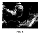
- One of the main features of the expanded graphite of the present invention is its particle shape, which allows for achievement of a low-weight percent carbon containing alkaline cell cathode.
- FIG 3 a photograph taken with a scanning electron microscope (SEM), magnified at a power of 5000 x, there is illustrated expanded graphite manufactured according to the aforementioned process.
- the expanded graphite crystals have a cupped or baseball-glove shaped configuration. This is in contrast to conventional crystalline graphite, which typically has a flatter, laminar surface.
- cupped-shaped configuration has the advantage of allowing the expanded graphite particles to have more contact points with the electrolytic manganese dioxide particles than conventional flat graphite and, thus, expanded graphite particles provide a lower, overall contact resistance, whereas a flat crystalline graphite would, theoretically, have only one contact point on its surface with an electrolytic manganese dioxide particle.
- the multiple contact points provided with the expanded graphite particles allow enhanced electrical contact and, therefore, allow for a reduction in the amount of graphite that is required in the cathode 20 of cell 10.
- the multiple contact points which are realised with the expanded graphite particles allow a greater number of conductive paths between manganese dioxide particles so that alternative electrically conductive paths are made available. This can be especially advantageous should oxidation or electrical discontinuity develop in one or more current paths.
- the expanded graphite particles may provide enhanced electrolyte retention.
- the expanded graphite particles can be mixed with the electrolytic manganese dioxide to form the cathode 20, as follows.
- the expanded graphite may be used to form cathode mixes with different conductivities based on the electrolytic manganese dioxide used, as one manganese dioxide may provide a better fit with a cup-shaped expanded graphite particles than others, particularly based on particle shape and size of the expanded graphite. Such parameters can be optimised as necessary.
- the electrolytic manganese dioxide and cup-shaped expanded graphite particles are mixed together in a mixer for a short time at a high intensity.
- the mixer may be an FS Series Model No. LFS-GS-2J, manufactured and sold by the Fukae Powtec Corp. of Japan, having a blender with a vertically oriented agitator blade that pushes the material to the sides of a specially shaped drum.
- On the side of the drum of the mixer is a small, highspeed chopper blade that performs the actual mixing.
- the design of the drum affords even blending of all portions of the added powder.
- electrolytic manganese dioxide and expanded graphite particles be mixed for a period of three to seven minutes at a speed of 250-1000 RPM with an agitator blade and at a speed of 680-2500 RPM with a chopper blade. Extended mixing may result in finely ground expanded graphite particles and increased electrical resistivity.
- the heaviest material particularly the electrolytic manganese dioxide
- the lighter materials such as the expanded graphite particles.
- the electrolytic manganese dioxide and expanded graphite materials should not separate during subsequent handling.
- the cell's bulk cathode preferably contains an amount of expanded graphite in the range of 3.2% to 6.25% by weight of the total cathode, and more particularly contains expanded graphite of approximately 5% by weight of the total cathode.
- expanded graphite consumes less volume and weight than conventional graphite currently used in alkaline cells.
- additional volume remains available in the cathode to employ added electrolytic manganese dioxide or other active cathode materials, thereby leading to enhanced service performance of the cell, particularly for high-rate service applications.
- the half-cell configuration involves the testing of a 0.5 gram cathode pellet in a flooded electrolyte condition.
- a 100 mA/g electrolytic manganese dioxide discharge corresponds to approximately 1000 mA constant current discharge for a current standard size AA electrochemical cell.
- a 20 : 1 weight ratio of electrolytic manganese dioxide: carbon in the cathode mixture was used, corresponding to 4.8% by weight of carbon in the mix.
- the expanded graphite of the present invention exhibited a d 50 average particle size of approximately 23.6 ⁇ m when measured with the Microtrac ful range analyser.
- the Microtrac full range analyser reading provides a d 50 average particle size and d 90 and d 10 values.
- a suitable Microtrac full range analyser is the Model No. 9200 Series, manufactured and sold by Microtrac, Inc.
- the Microtrac full range analyser also initially calculates the area and perimeter of the measured particles, from which a volume can be calculated.
- the Microtrac full range analyser further determines a mean average volume and mean average area of the measured particles. According to the present invention, it is preferred that a d 50 average particle size be in the range of 17 to 32 ⁇ m, as measured with the Microtrac full range analyser.
- samples S1 through S17 were analysed as to performance and physical characteristics.
- a service time was measured in minutes to reach a 0.9-volt cut-off, in accordance with a 100 mA/g electrolytic manganese dioxide discharge for the flooded half-cell test.
- Sample S1 achieved the highest service performance of 97.1 minutes.
- the average particle size (d 50 ), d 90 value and d 10 value (in micrometers), as measured with the Microtrac full range analyser are provided, along with the calculated mean diameter of volume and mean diameter of area, as calculated by the Microtrac full range analyser.
- Figures 5-10 selected measured test data, which are shown in the table of Figure 4, are shown plotted in graphs and can be used to determine an optimum expanded graphite for use in a cathode of a cell.
- Figure 5 illustrates the mean diameter of volume versus service performance time in minutes for each of the samples S1-S17 of expanded graphite, as measured with the Microtrac full range analyser.
- Figure 6 illustrates the mean diameter of area, as measured with the Microtrac full range analyser along with the service performance time in minutes.
- Figure 7 illustrates the kerosene absorption of the expanded graphite in millilitres per gram (ml/g) versus the service performance time.
- Figure 8 illustrates a measurement of the Scott volume in grams per cubic inch (g/in 3 ) (grams per 16.39 cm 3 ) versus the service performance time.
- Figure 9 illustrates the expanded graphite BET surface area in meters squared per gram (m 2 /g) versus the service performance time, while
- Figure 10 illustrates the cathode pellet resistance in ohms versus the service performance time.
- the physical characteristics of the expanded graphite particles can be measured with the Microtrac full range analyser or other comparable particle analyser. Physical characteristics of expanded graphite particles that can be measured with such a particle analyser include the mean diameter of volume, mean diameter of area and a calculated surface area.
- Kerosene absorption is an indication of the ability of the expanded graphite to absorb electrolyte, relative to kerosene.
- the expanded graphite of the present invention has a kerosene absorption in the range of 2.7 to 3.1 millilitres per gram (ml/g). Kerosene absorption measurements can be provided by wetting a fixed amount of expanded graphite with kerosene/surfactant solution made up of 96% kerosene and 4% dimethyl di(cocoalkyl) quaternary ammonium chlorides, one example of which is commercially available as ARQUAD 2C-75 from Akzo Nobel Chemicals, Inc. The kerosene is added at a fixed rate, with continuous agitation, until expanded graphite agglomerates join and become a single ball, at which time an absorption value is determined by the number of millilitres of test solution added to the sample.
- the kerosene absorption test procedure includes adding 10 to 25 grams, plus or minus 0.1 gram, of a sample of expanded graphite to a clean, dry 500 millilitre Erlenmeyer flask, and inserting the flask in a holder of a shaking machine.
- the tip of a burette is adjusted to a preferred height of about one inch (2.54 cm) above the mouth of the flask.
- the shaker may be a Burrell wrist action shaker Model No. BB, made available by Burrell Scientific, or equivalent, with the amplitude lever set to position "5" to produce a mild agitation of a sample in the flask.
- a stopcock on the burette is opened and the kerosene solution is dispensed at the rate of three to four drops per second, which corresponds to approximately nine to twelve millilitres per second.
- the amplitude of the lever of the shaker is preferably raised to position "10" and, also, the solution being added should be reduced to one drop per second, to avoid passing the end point.
- small balls combine with one another to produce larger balls and, as the end point approaches, a desired single ball is realised.
- the burette reading is recorded and the absorption value is equal to the number of millilitres of test solution added to the sample.
- other measured test data may include a tap density value of the expanded graphite.
- the tap density testing procedure includes subjecting a fixed sample weight of expanded graphite to a predetermined number of taps, such as 1,000 taps, at a first frequency over a period of time, such as four minutes, in a graduated cylinder to achieve packing, e.g ., filling in of voids, in a consistent and repeatable manner.
- the procedure includes weighing the predetermined amount of expanded graphite in a graduated cylinder using a powder funnel.
- the cylinder may be placed in a dual auto tap device such as Model No. DA1, made available from the Quantachrome Corporation.
- the dual auto tap device is set to provide uniform repeated taps to the cylinder for the predetermined period of time to provide a predetermined number of taps.
- the cylinder is then removed from the apparatus and the volume of the sample of expanded graphite is measured.
- the expanded graphite is weighed.
- the tap density value is a function of the measured weight in grams of expanded graphite divided by the measured volume following the tap density testing procedure. This tap density testing procedure provides for a tap density value in grams per cubic centimetres (g/cc).
- the graph provides an illustration of measured tap density values as determined in accordance with the aforementioned tap density testing procedure.
- the tap density is provided as a function of the service performance time and minutes for each of the samples of expanded graphite to reach a cut-off voltage of 0.9 volts.
- the expanded graphite particles of the present invention are purified to a high purity level.
- the following table lists the desired maximum amount of impurities in parts-per-million (PPM) for each impurity that may be present in the expanded graphite particles: TOTAL IMPURITIES MAXIMUM LIMITS (PPM) a) Antimony (Sb)* 2.0 b) Arsenic (As)* 1.0 c) Molybdenum (Mo)* 2.0 d) Vanadium (V)* 10.0 e) Chromium (Cr)* 5.0 f) Iron (Fe)* 150.0 g) Copper (Cu)* 5.0 h) Tin (Sn)* 2.0 i) Aluminium (Al) 25.0 j) Calcium (Ca) 75.0 k) Cobalt (Co) 3.0 l) Lead (Pb) 5.0 m) Nickel (Ni) 5.0 n) Silicon (Si) 200.0
- the preferred expanded graphite realises an aggregate total maximum limit of no more than 490 ppm of impurities, amounting to 0.049% impurities or 99.951% pure expanded graphite. It is preferred that the expanded graphite particles have a purity of at least 99.95% or higher.
- the impurities deemed most critical are marked with an (*) and include antimony, arsenic, molybdenum, vanadium, chromium, iron, copper, and tin, which together should preferably have an aggregate total maximum allowed amount of no more than 170 ppm of critical impurities, amounting to 0.017% critical impurities or 99.983% non-critical impurities.
- the expanded graphite particles have a kerosene absorption value in the range of 2.7 to 3.1 millilitres per gram. Further, it is preferred that the expanded graphite have both an average particle size in the range of 17 to 32 ⁇ m and a d 90 value in the range of 40 to 85 micrometers, and yet more preferred that the expanded graphite also have an average surface area-to-mass ratio of greater than or equal to 18 m 2 /gram.
- the most preferred particle size distribution of the expanded graphite is defined by an average particle size of 17 to 32 micrometers, a d 90 value of 40 to 85 ⁇ m and a d 10 value of 3-9 micrometers.
- the tap density have a preferred value in the range of 0.09 to 0.14 g/cc. It is further preferred that the expanded graphite have a Scott density no greater than 0.07 grams/millilitre (g/ml), and preferably no greater than 0.05 g/ml.
- a non-acid treated, de-laminated graphite may be used in place of the acid-soaked, thermally treated, expanded graphite described above.
- the non-acid treated, de-laminated graphite is processed in a thermal treatment process, but does not require the use of acid soaking. Instead, a natural graphite is placed in an oven and heat treated as explained above, but without the acid soaking treatment.
- the non-acid, thermal treatment process causes the natural graphite to de-laminate to form multiple thin graphite strips.
- a chemically treated synthetic expanded graphite can be used.
- This chemically treated, synthetic expanded graphite can be used in cathode mix ratios with electrolytic manganese dioxide of 20 : 1 oxide-to-carbon weight ratio.
- the synthetic expanded graphite exhibits a high-rate performance at 50 mA/g manganese dioxide constant current.
- Cathode mixes containing this synthetic, chemically treated expanded graphite have also shown low cathode pellet resistivities with values in the range of cathode mixes containing a thermally prepared expanded graphite as explained above.
- standard AA-size cells containing this specific synthetic expanded graphite in the cathode exhibit high-rate service performance greater than current factory products, as this material provides increased cathodic service performance in both ring-moulded and impact-moulded cathode assemblies.
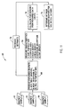
- a method 60 for determining an optimum expanded graphite from numerous samples for use in the cathode 20 of the electrochemical cell 10.
- the method includes sampling one graphite at a time, from a plurality of graphite samples, such as graphite Sample A 62, Sample B 64, and Sample C 66, as shown.
- Each sample of graphite may include natural graphite obtained from a mine and purified in a purity process.
- Graphite obtained from different mines and purified by different processes may produce differing characteristics which, in turn, may affect the characteristics of an expanded graphite produced therefrom.
- methodology 60 includes the step 68 of producing an expanded graphite.
- the expanded graphite may be produced according to the above-described method 40, as set forth in Figure 2, which includes acid treatment, heating, and milling to achieve a particular particle size, shape, and other characteristics.
- step 70 of method 60 measures various characteristics of the produced expanded graphite particles. Measurements include measuring the average particle size of the expanded graphite, such as the d 50 , d 90 and d 10 average particle size measurements, as taken with a Microtrac measuring device. Another measuring characteristic includes measuring the surface area of the expanded graphite particles, preferably taken as an average surface area. The bulk density, as well as real density, of the expanded graphite is also measured. Density is measured in grams per cubic inch (grams per 16.39 cm 3 ), and may include a Scott volume. The measurement characteristics further include measuring the kerosene absorption for the expanded graphite, as well as tap density. It should be appreciated that other characteristics of the expanded graphite may likewise be measured and used in accordance with method 60.
- measured data curves can be produced from which the performance for a given expanded graphite may be calculated in step 72. Measured data curves may be similar to the graphs shown in Figures 5-10.
- step 74 Based on the calculated performance for the measured expanded graphite, in step 74 a determination is made as to the optimum expanded graphite for use in the cathode 20 of cell 10 by comparing the calculated performance for various expanded graphites. For a given expanded graphite, the performance calculation may be used to adjust feedback set points, as set forth in block 76, which may be used in the production of the expanded graphite.
- Set point adjustments may include manual or automatic process control adjustments, such as adjusting the soaking time for acid treatment of the graphite, adjusting the time and temperature for heat treatment, and adjusting the milling speed and time used to obtain a particular expanded graphite average particle size.
- the calculated performance could be used to adjust the process of producing expanded graphite for a particular sample of graphite.
- various samples of graphite may be used to produce the expanded graphite, and the performance characteristics can be measured and compared to determine the optimum expanded graphite from the available samples.
Landscapes
- Chemical & Material Sciences (AREA)
- Organic Chemistry (AREA)
- Chemical Kinetics & Catalysis (AREA)
- Geology (AREA)
- Inorganic Chemistry (AREA)
- General Life Sciences & Earth Sciences (AREA)
- Life Sciences & Earth Sciences (AREA)
- Electrochemistry (AREA)
- General Chemical & Material Sciences (AREA)
- Battery Electrode And Active Subsutance (AREA)
- Carbon And Carbon Compounds (AREA)
- Primary Cells (AREA)
- Electrodes For Compound Or Non-Metal Manufacture (AREA)
Applications Claiming Priority (5)
| Application Number | Priority Date | Filing Date | Title |
|---|---|---|---|
| US7226998P | 1998-01-07 | 1998-01-07 | |
| US72269P | 1998-01-07 | ||
| US213544 | 1998-12-17 | ||
| US09/213,544 US6828064B1 (en) | 1998-01-07 | 1998-12-17 | Alkaline cell having a cathode incorporating enhanced graphite |
| PCT/US1999/000270 WO1999034673A1 (en) | 1998-01-07 | 1999-01-06 | Alkaline cell having a cathode incorporating expanded graphite |
Publications (2)
| Publication Number | Publication Date |
|---|---|
| EP1044477A1 EP1044477A1 (en) | 2000-10-18 |
| EP1044477B1 true EP1044477B1 (en) | 2003-04-02 |
Family
ID=26753180
Family Applications (1)
| Application Number | Title | Priority Date | Filing Date |
|---|---|---|---|
| EP99902069A Expired - Lifetime EP1044477B1 (en) | 1998-01-07 | 1999-01-06 | Alkaline cell having a cathode incorporating expanded graphite |
Country Status (9)
| Country | Link |
|---|---|
| US (1) | US6828064B1 (enExample) |
| EP (1) | EP1044477B1 (enExample) |
| JP (1) | JP4416320B2 (enExample) |
| CN (1) | CN1146063C (enExample) |
| AT (1) | ATE236455T1 (enExample) |
| AU (1) | AU2213999A (enExample) |
| CA (1) | CA2316926A1 (enExample) |
| DE (2) | DE69906476T2 (enExample) |
| WO (1) | WO1999034673A1 (enExample) |
Families Citing this family (27)
| Publication number | Priority date | Publication date | Assignee | Title |
|---|---|---|---|---|
| CH710862B1 (de) * | 1999-11-26 | 2016-09-15 | Imerys Graphite & Carbon Switzerland Sa | Verfahren zur Herstellung von Graphitpulvern mit erhöhter Schüttdichte. |
| US6660434B2 (en) | 2000-03-06 | 2003-12-09 | Superior Graphite Co. | Engineered carbonaceous materials and power sources using these materials |
| US6451486B1 (en) | 2000-05-01 | 2002-09-17 | The Gillette Company | Battery cathode including a mixture of manganese dioxide with carbon particles of expanded and non-expanded graphite |
| CA2324431A1 (fr) | 2000-10-25 | 2002-04-25 | Hydro-Quebec | Nouveau procede d'obtention de particule du graphite naturel sous forme spherique: modelisation et application |
| US6596438B2 (en) * | 2001-06-13 | 2003-07-22 | The Gillette Company | Alkaline cell with improved cathode |
| US6921610B2 (en) * | 2001-07-11 | 2005-07-26 | The Gillette Company | Battery |
| AU2002349317A1 (en) * | 2001-10-08 | 2003-04-22 | Timcal Ag | Electrochemical cell |
| KR100599602B1 (ko) * | 2004-10-28 | 2006-07-13 | 삼성에스디아이 주식회사 | 리튬 이차 전지용 양극 및 이를 포함하는 리튬 이차 전지 |
| US20070009799A1 (en) | 2005-07-07 | 2007-01-11 | Eveready Battery Company, Inc. | Electrochemical cell having a partially oxidized conductor |
| DE102006021158A1 (de) * | 2006-05-06 | 2007-11-08 | Biotronik Crm Patent Ag | Elektrode für eine Lithiumbatterie und Verfahren zur Herstellung derselben |
| JP2010500446A (ja) * | 2006-08-10 | 2010-01-07 | ダウ グローバル テクノロジーズ インコーポレイティド | 高膨張黒鉛を充填したポリマー |
| WO2008021035A1 (en) * | 2006-08-10 | 2008-02-21 | Dow Global Technologies, Inc. | Polymers of macrocyclic oligomers containing highly expanded graphite |
| US20080050654A1 (en) * | 2006-08-23 | 2008-02-28 | Maya Stevanovic | Battery |
| CN101521119B (zh) * | 2007-04-20 | 2011-03-16 | 哈尔滨工程大学 | 膨胀石墨/金属氧化物复合材料的制备方法 |
| BRPI0703826A2 (pt) * | 2007-08-28 | 2009-04-28 | Nac De Grafite Ltda | bateria alcalina |
| US20090202910A1 (en) * | 2008-02-08 | 2009-08-13 | Anglin David L | Alkaline Batteries |
| BRPI1006680B1 (pt) * | 2009-04-15 | 2020-10-27 | Dow Global Technologies Llc | processo para manufaturar um óxido de grafita isolado criogenicamente secado |
| CN101908625B (zh) * | 2009-06-03 | 2014-02-05 | 法拉赛斯能源公司 | 用于锂离子电池的复合材料及其制备方法 |
| KR101084069B1 (ko) * | 2010-06-17 | 2011-11-16 | 삼성에스디아이 주식회사 | 층간 거리가 조절된 결정성 탄소 재료 및 그의 제조 방법 |
| JP5688264B2 (ja) * | 2010-10-20 | 2015-03-25 | 東洋炭素株式会社 | 膨張黒鉛シート及びその製造方法 |
| CN103181018B (zh) * | 2010-10-27 | 2015-07-15 | 丰田自动车株式会社 | 锂离子二次电池制造方法 |
| JP6241737B2 (ja) * | 2014-01-16 | 2017-12-06 | パナソニックIpマネジメント株式会社 | アルカリ電池及びその製造方法 |
| WO2016064532A1 (en) * | 2014-10-22 | 2016-04-28 | Cabot Corporation | Carbon additives for negative electrodes |
| KR101818703B1 (ko) | 2014-12-11 | 2018-01-16 | 주식회사 엘지화학 | 고속 균질화 전처리 및 고압 균질화를 이용한 그래핀의 제조 방법 |
| US10177375B2 (en) | 2016-08-10 | 2019-01-08 | Energizer Brands, Llc | Alkaline battery cathode structures incorporating multiple carbon materials and orientations |
| JP7080188B2 (ja) * | 2017-02-08 | 2022-06-03 | 凸版印刷株式会社 | アルカリ二次電池用正極及びアルカリ二次電池 |
| CN119683618A (zh) * | 2024-12-20 | 2025-03-25 | 清华大学 | 一种分级天然石墨颗粒制备多孔石墨块体的方法 |
Family Cites Families (40)
| Publication number | Priority date | Publication date | Assignee | Title |
|---|---|---|---|---|
| US2734799A (en) | 1956-02-14 | Brooks | ||
| US2914383A (en) | 1951-11-16 | 1959-11-24 | Graphitwerk Kropfmuhl Ag | Process of purifying graphite |
| GB991581A (en) | 1962-03-21 | 1965-05-12 | High Temperature Materials Inc | Expanded pyrolytic graphite and process for producing the same |
| US3560155A (en) | 1966-03-30 | 1971-02-02 | Dow Chemical Co | Graphite product |
| US3389964A (en) | 1966-04-04 | 1968-06-25 | Dow Chemical Co | Process for preparing low density graphite structrues |
| US3414381A (en) | 1966-04-04 | 1968-12-03 | Dow Chemical Co | Method for producing low density graphite structures |
| US3409563A (en) | 1966-04-04 | 1968-11-05 | Dow Chemical Co | Hyperconductive graphite structures |
| US3719608A (en) | 1968-11-12 | 1973-03-06 | Dow Chemical Co | Oxidation resistant graphite compositions |
| US3807961A (en) | 1970-02-24 | 1974-04-30 | Superior Graphite Co | Apparatus for high-temperature treatment of petroleum coke |
| DE2237363A1 (de) | 1972-07-29 | 1974-02-14 | Rhein Westfael Elect Werk Ag | Primaerelement |
| US4146401A (en) | 1975-08-02 | 1979-03-27 | Hitachi Chemical Company, Ltd. | Graphite material having compressibility and recovering property and method for manufacturing the same |
| US4102960A (en) | 1976-12-15 | 1978-07-25 | Stackpole Carbon Company | Process for making high strength flexible graphite foil |
| US4175022A (en) | 1977-04-25 | 1979-11-20 | Union Carbide Corporation | Electrolytic cell bottom barrier formed from expanded graphite |
| DE2748135C2 (de) | 1977-10-27 | 1982-10-14 | Sigri Elektrographit Gmbh, 8901 Meitingen | Flexibler Graphitschichtstoff |
| US4265952A (en) | 1978-03-23 | 1981-05-05 | The Dow Chemical Company | Vermicular expanded graphite composite material |
| JPS5690989A (en) | 1979-12-14 | 1981-07-23 | Nobuatsu Watanabe | Manufacture of interlaminar compound of graphite |
| JPS56109460A (en) | 1980-02-04 | 1981-08-29 | Japan Storage Battery Co Ltd | Lead storage battery |
| JPS56118267A (en) | 1980-02-20 | 1981-09-17 | Hitachi Maxell Ltd | Dry cell |
| JPS56128578A (en) | 1980-03-12 | 1981-10-08 | Hitachi Maxell Ltd | Alkaline battery |
| DE3022449A1 (de) | 1980-06-14 | 1982-01-07 | Brown, Boveri & Cie Ag, 6800 Mannheim | Elektrochemische speicherzelle |
| JPS58129764A (ja) | 1982-01-28 | 1983-08-02 | Sanyo Electric Co Ltd | 非水電解液電池 |
| JPS6065781A (ja) | 1983-09-20 | 1985-04-15 | 日立化成工業株式会社 | 不浸透性膨張黒鉛成形体 |
| JPS60118618A (ja) | 1983-11-25 | 1985-06-26 | Nippon Pillar Packing Co Ltd | 膨張黒鉛に含まれる残留イオウの低減方法 |
| JPS61107663A (ja) | 1984-06-29 | 1986-05-26 | ユニオン、カ−バイド、コ−ポレ−シヨン | 酸化銀電池用蠕虫状膨張黒鉛導体 |
| JPS63232266A (ja) | 1987-03-20 | 1988-09-28 | Toshiba Battery Co Ltd | アルカリ乾電池 |
| US4895713A (en) | 1987-08-31 | 1990-01-23 | Union Carbide Corporation | Intercalation of graphite |
| US4826181A (en) | 1988-02-09 | 1989-05-02 | Union Carbide Corporation | Seal utilizing composites of flexible graphite particles and amorphous carbon |
| US5186919A (en) | 1988-11-21 | 1993-02-16 | Battelle Memorial Institute | Method for producing thin graphite flakes with large aspect ratios |
| IL92872A (en) | 1989-12-25 | 1992-07-15 | Technion Res & Dev Foundation | Removal of oil from water |
| US5282975A (en) * | 1989-12-25 | 1994-02-01 | Technion Research And Development Foundation Ltd. | Removal of oil from water |
| FR2682370B1 (fr) | 1991-10-15 | 1994-01-07 | Centre Nal Recherc Scientifique | Graphite micronique plat, procede pour sa preparation et ses applications. |
| IL103641A (en) | 1992-11-04 | 1996-11-14 | Environmental Systems Ltd | Expandable graphite compositions for absorption of liquids and method for the manufacture thereof |
| JP3450894B2 (ja) * | 1994-03-28 | 2003-09-29 | 松下電器産業株式会社 | アルカリマンガン電池 |
| JP3216451B2 (ja) | 1994-12-12 | 2001-10-09 | 松下電器産業株式会社 | 非水電解液電池 |
| JPH09129239A (ja) | 1995-10-31 | 1997-05-16 | Matsushita Electric Ind Co Ltd | 有機電解質電池 |
| US5772930A (en) * | 1995-12-27 | 1998-06-30 | Matsushita Electric Industrial Co., Ltd. | Method of producing cathode mixture for batteries |
| DE19615845A1 (de) * | 1996-04-20 | 1997-10-23 | Varta Batterie | Kathodenzusatz für alkalische Primärzellen |
| JPH10188993A (ja) | 1996-12-24 | 1998-07-21 | Ricoh Co Ltd | 非水電解質二次電池 |
| JP3054757B2 (ja) | 1997-03-03 | 2000-06-19 | 大阪府 | 膨張黒鉛系組成物、成形体および焼成体ならびにその製造方法 |
| JP3188853B2 (ja) | 1997-04-01 | 2001-07-16 | セイコーインスツルメンツ株式会社 | 非水電解質二次電池 |
-
1998
- 1998-12-17 US US09/213,544 patent/US6828064B1/en not_active Expired - Lifetime
-
1999
- 1999-01-06 EP EP99902069A patent/EP1044477B1/en not_active Expired - Lifetime
- 1999-01-06 DE DE69906476T patent/DE69906476T2/de not_active Expired - Lifetime
- 1999-01-06 WO PCT/US1999/000270 patent/WO1999034673A1/en not_active Ceased
- 1999-01-06 DE DE1044477T patent/DE1044477T1/de active Pending
- 1999-01-06 CN CNB998037621A patent/CN1146063C/zh not_active Expired - Lifetime
- 1999-01-06 JP JP2000527145A patent/JP4416320B2/ja not_active Expired - Fee Related
- 1999-01-06 AT AT99902069T patent/ATE236455T1/de not_active IP Right Cessation
- 1999-01-06 AU AU22139/99A patent/AU2213999A/en not_active Abandoned
- 1999-01-06 CA CA002316926A patent/CA2316926A1/en not_active Abandoned
Also Published As
| Publication number | Publication date |
|---|---|
| HK1027906A1 (en) | 2001-01-23 |
| DE1044477T1 (de) | 2001-01-25 |
| EP1044477A1 (en) | 2000-10-18 |
| JP4416320B2 (ja) | 2010-02-17 |
| JP2002500428A (ja) | 2002-01-08 |
| DE69906476T2 (de) | 2004-02-12 |
| DE69906476D1 (de) | 2003-05-08 |
| AU2213999A (en) | 1999-07-26 |
| CN1292936A (zh) | 2001-04-25 |
| US6828064B1 (en) | 2004-12-07 |
| WO1999034673A1 (en) | 1999-07-15 |
| CN1146063C (zh) | 2004-04-14 |
| CA2316926A1 (en) | 1999-07-15 |
| ATE236455T1 (de) | 2003-04-15 |
Similar Documents
| Publication | Publication Date | Title |
|---|---|---|
| EP1044477B1 (en) | Alkaline cell having a cathode incorporating expanded graphite | |
| US11949096B2 (en) | Positive electrode material for rechargeable lithium ion batteries | |
| Audemer et al. | Electrochemical and Raman studies of beta‐type nickel hydroxides Ni1− xCox (OH) 2 electrode materials | |
| EP1069633B1 (en) | Active material of positive electrode for non-aqueous electrode secondary battery and method for preparing the same and non-aqueous electrode secondary battery using the same | |
| KR20090065527A (ko) | 미세분말 화합물, 그의 제조 방법 및 리튬 이차 전지에서의 그의 용도 | |
| JPH0922693A (ja) | 非水電解液電池およびその正極活物質と正極板の製造法 | |
| EP0817292B1 (en) | Alkaline storage battery and method of producing Ni/Co hydroxide active mass for positive electrode | |
| WO2005028569A2 (en) | Thermally modified carbon blacks for various type applications and a process for producing same | |
| US20070009799A1 (en) | Electrochemical cell having a partially oxidized conductor | |
| JP2005505904A (ja) | 電気化学的電池 | |
| AU2019203185B1 (en) | Doped lithium positive electrode active material and process for manufacture thereof | |
| US6660434B2 (en) | Engineered carbonaceous materials and power sources using these materials | |
| EP3439080A1 (en) | Negative electrode for alkali secondary battery, alkali secondary battery including negative electrode and method for producing negative electrode | |
| HK1027906B (en) | Alkaline cell having a cathode incorporating expanded graphite | |
| JP3114402B2 (ja) | アルカリ蓄電池の製造方法 | |
| KR102318270B1 (ko) | 배터리의 음극에 사용하기 위한 활성 물질 분말 및 상기 활성 물질 분말을 포함하는 배터리 | |
| EP1714337B1 (en) | Electrochemical cell incorporating zinc in the anode | |
| TW434936B (en) | Alkaline cell having a cathode incorporating enhanced graphite | |
| KR102563893B1 (ko) | 나트륨 이온 2차 전지용 복합 음극재의 제조방법 및 그에 의해 제조된 복합 음극재 | |
| JP2024534889A (ja) | シリコン-カーボン複合材料の製造方法 | |
| JPH08138673A (ja) | 非水リチウム二次電池用正極活物質およびリチウム二次電池 | |
| JPH08339800A (ja) | 水素吸蔵合金電極、その製造方法及び金属水素化物蓄電池 |
Legal Events
| Date | Code | Title | Description |
|---|---|---|---|
| PUAI | Public reference made under article 153(3) epc to a published international application that has entered the european phase |
Free format text: ORIGINAL CODE: 0009012 |
|
| 17P | Request for examination filed |
Effective date: 20000710 |
|
| AK | Designated contracting states |
Kind code of ref document: A1 Designated state(s): AT BE CH CY DE DK ES FI FR GB GR IE IT LI LU MC NL PT SE |
|
| EL | Fr: translation of claims filed | ||
| TCNL | Nl: translation of patent claims filed | ||
| DET | De: translation of patent claims | ||
| 17Q | First examination report despatched |
Effective date: 20010525 |
|
| GRAG | Despatch of communication of intention to grant |
Free format text: ORIGINAL CODE: EPIDOS AGRA |
|
| GRAG | Despatch of communication of intention to grant |
Free format text: ORIGINAL CODE: EPIDOS AGRA |
|
| GRAH | Despatch of communication of intention to grant a patent |
Free format text: ORIGINAL CODE: EPIDOS IGRA |
|
| GRAH | Despatch of communication of intention to grant a patent |
Free format text: ORIGINAL CODE: EPIDOS IGRA |
|
| GRAA | (expected) grant |
Free format text: ORIGINAL CODE: 0009210 |
|
| AK | Designated contracting states |
Designated state(s): AT BE CH CY DE DK ES FI FR GB GR IE IT LI LU MC NL PT SE |
|
| PG25 | Lapsed in a contracting state [announced via postgrant information from national office to epo] |
Ref country code: NL Free format text: LAPSE BECAUSE OF FAILURE TO SUBMIT A TRANSLATION OF THE DESCRIPTION OR TO PAY THE FEE WITHIN THE PRESCRIBED TIME-LIMIT Effective date: 20030402 Ref country code: IT Free format text: LAPSE BECAUSE OF FAILURE TO SUBMIT A TRANSLATION OF THE DESCRIPTION OR TO PAY THE FEE WITHIN THE PRE;WARNING: LAPSES OF ITALIAN PATENTS WITH EFFECTIVE DATE BEFORE 2007 MAY HAVE OCCURRED AT ANY TIME BEFORE 2007. THE CORRECT EFFECTIVE DATE MAY BE DIFFERENT FROM THE ONE RECORDED.SCRIBED TIME-LIMIT Effective date: 20030402 Ref country code: FR Free format text: LAPSE BECAUSE OF FAILURE TO SUBMIT A TRANSLATION OF THE DESCRIPTION OR TO PAY THE FEE WITHIN THE PRESCRIBED TIME-LIMIT Effective date: 20030402 Ref country code: FI Free format text: LAPSE BECAUSE OF FAILURE TO SUBMIT A TRANSLATION OF THE DESCRIPTION OR TO PAY THE FEE WITHIN THE PRESCRIBED TIME-LIMIT Effective date: 20030402 Ref country code: CY Free format text: LAPSE BECAUSE OF FAILURE TO SUBMIT A TRANSLATION OF THE DESCRIPTION OR TO PAY THE FEE WITHIN THE PRESCRIBED TIME-LIMIT Effective date: 20030402 Ref country code: AT Free format text: LAPSE BECAUSE OF FAILURE TO SUBMIT A TRANSLATION OF THE DESCRIPTION OR TO PAY THE FEE WITHIN THE PRESCRIBED TIME-LIMIT Effective date: 20030402 |
|
| REG | Reference to a national code |
Ref country code: GB Ref legal event code: FG4D |
|
| REG | Reference to a national code |
Ref country code: CH Ref legal event code: NV Representative=s name: RITSCHER & PARTNER AG PATENTANWAELTE Ref country code: CH Ref legal event code: EP |
|
| REG | Reference to a national code |
Ref country code: IE Ref legal event code: FG4D |
|
| REF | Corresponds to: |
Ref document number: 69906476 Country of ref document: DE Date of ref document: 20030508 Kind code of ref document: P |
|
| PG25 | Lapsed in a contracting state [announced via postgrant information from national office to epo] |
Ref country code: SE Free format text: LAPSE BECAUSE OF FAILURE TO SUBMIT A TRANSLATION OF THE DESCRIPTION OR TO PAY THE FEE WITHIN THE PRESCRIBED TIME-LIMIT Effective date: 20030702 Ref country code: PT Free format text: LAPSE BECAUSE OF FAILURE TO SUBMIT A TRANSLATION OF THE DESCRIPTION OR TO PAY THE FEE WITHIN THE PRESCRIBED TIME-LIMIT Effective date: 20030702 Ref country code: GR Free format text: LAPSE BECAUSE OF FAILURE TO SUBMIT A TRANSLATION OF THE DESCRIPTION OR TO PAY THE FEE WITHIN THE PRESCRIBED TIME-LIMIT Effective date: 20030702 Ref country code: DK Free format text: LAPSE BECAUSE OF FAILURE TO SUBMIT A TRANSLATION OF THE DESCRIPTION OR TO PAY THE FEE WITHIN THE PRESCRIBED TIME-LIMIT Effective date: 20030702 |
|
| NLV1 | Nl: lapsed or annulled due to failure to fulfill the requirements of art. 29p and 29m of the patents act | ||
| PG25 | Lapsed in a contracting state [announced via postgrant information from national office to epo] |
Ref country code: ES Free format text: LAPSE BECAUSE OF FAILURE TO SUBMIT A TRANSLATION OF THE DESCRIPTION OR TO PAY THE FEE WITHIN THE PRESCRIBED TIME-LIMIT Effective date: 20031030 |
|
| PG25 | Lapsed in a contracting state [announced via postgrant information from national office to epo] |
Ref country code: LU Free format text: LAPSE BECAUSE OF NON-PAYMENT OF DUE FEES Effective date: 20040106 Ref country code: IE Free format text: LAPSE BECAUSE OF NON-PAYMENT OF DUE FEES Effective date: 20040106 |
|
| PG25 | Lapsed in a contracting state [announced via postgrant information from national office to epo] |
Ref country code: MC Free format text: LAPSE BECAUSE OF NON-PAYMENT OF DUE FEES Effective date: 20040131 Ref country code: LI Free format text: LAPSE BECAUSE OF NON-PAYMENT OF DUE FEES Effective date: 20040131 Ref country code: CH Free format text: LAPSE BECAUSE OF NON-PAYMENT OF DUE FEES Effective date: 20040131 |
|
| PLBE | No opposition filed within time limit |
Free format text: ORIGINAL CODE: 0009261 |
|
| STAA | Information on the status of an ep patent application or granted ep patent |
Free format text: STATUS: NO OPPOSITION FILED WITHIN TIME LIMIT |
|
| EN | Fr: translation not filed | ||
| 26N | No opposition filed |
Effective date: 20040105 |
|
| REG | Reference to a national code |
Ref country code: CH Ref legal event code: PL |
|
| REG | Reference to a national code |
Ref country code: IE Ref legal event code: MM4A |
|
| REG | Reference to a national code |
Ref country code: DE Ref legal event code: R081 Ref document number: 69906476 Country of ref document: DE Owner name: ENERGIZER BRANDS, LLC (N.D.GES.D. STAATES DELA, US Free format text: FORMER OWNER: EVEREADY BATTERY CO., INC., WESTLAKE, OHIO, US |
|
| PGFP | Annual fee paid to national office [announced via postgrant information from national office to epo] |
Ref country code: GB Payment date: 20160127 Year of fee payment: 18 Ref country code: BE Payment date: 20160127 Year of fee payment: 18 |
|
| REG | Reference to a national code |
Ref country code: GB Ref legal event code: 732E Free format text: REGISTERED BETWEEN 20161013 AND 20161019 |
|
| PG25 | Lapsed in a contracting state [announced via postgrant information from national office to epo] |
Ref country code: BE Free format text: LAPSE BECAUSE OF NON-PAYMENT OF DUE FEES Effective date: 20170131 |
|
| GBPC | Gb: european patent ceased through non-payment of renewal fee |
Effective date: 20170106 |
|
| PG25 | Lapsed in a contracting state [announced via postgrant information from national office to epo] |
Ref country code: GB Free format text: LAPSE BECAUSE OF NON-PAYMENT OF DUE FEES Effective date: 20170106 |
|
| REG | Reference to a national code |
Ref country code: BE Ref legal event code: PD Owner name: ENERGIZER BRANDS, LLC; US Free format text: DETAILS ASSIGNMENT: CHANGE OF OWNER(S), AUTRE, CHANGEMENT D'ADRESSE Effective date: 20150921 Ref country code: BE Ref legal event code: MM Effective date: 20170131 |
|
| PGFP | Annual fee paid to national office [announced via postgrant information from national office to epo] |
Ref country code: DE Payment date: 20171228 Year of fee payment: 20 |
|
| REG | Reference to a national code |
Ref country code: DE Ref legal event code: R071 Ref document number: 69906476 Country of ref document: DE |