EP1042616B1 - Impulsgesteuertes pneumatisches 4/2-wegeventil - Google Patents
Impulsgesteuertes pneumatisches 4/2-wegeventil Download PDFInfo
- Publication number
- EP1042616B1 EP1042616B1 EP99952432A EP99952432A EP1042616B1 EP 1042616 B1 EP1042616 B1 EP 1042616B1 EP 99952432 A EP99952432 A EP 99952432A EP 99952432 A EP99952432 A EP 99952432A EP 1042616 B1 EP1042616 B1 EP 1042616B1
- Authority
- EP
- European Patent Office
- Prior art keywords
- valve
- pulse
- pneumatic
- controlled
- directional valve
- Prior art date
- Legal status (The legal status is an assumption and is not a legal conclusion. Google has not performed a legal analysis and makes no representation as to the accuracy of the status listed.)
- Expired - Lifetime
Links
- 230000002441 reversible effect Effects 0.000 claims 1
- 238000007789 sealing Methods 0.000 description 5
- 230000008901 benefit Effects 0.000 description 3
- 238000010276 construction Methods 0.000 description 3
- 238000007792 addition Methods 0.000 description 1
- 230000000903 blocking effect Effects 0.000 description 1
- 238000004891 communication Methods 0.000 description 1
- 230000008878 coupling Effects 0.000 description 1
- 238000010168 coupling process Methods 0.000 description 1
- 238000005859 coupling reaction Methods 0.000 description 1
- 238000011161 development Methods 0.000 description 1
- 230000018109 developmental process Effects 0.000 description 1
- 238000010586 diagram Methods 0.000 description 1
- 230000008030 elimination Effects 0.000 description 1
- 238000003379 elimination reaction Methods 0.000 description 1
- 230000003993 interaction Effects 0.000 description 1
- 238000000034 method Methods 0.000 description 1
- 230000007935 neutral effect Effects 0.000 description 1
- 230000008569 process Effects 0.000 description 1
- 230000009885 systemic effect Effects 0.000 description 1
Images
Classifications
-
- F—MECHANICAL ENGINEERING; LIGHTING; HEATING; WEAPONS; BLASTING
- F15—FLUID-PRESSURE ACTUATORS; HYDRAULICS OR PNEUMATICS IN GENERAL
- F15B—SYSTEMS ACTING BY MEANS OF FLUIDS IN GENERAL; FLUID-PRESSURE ACTUATORS, e.g. SERVOMOTORS; DETAILS OF FLUID-PRESSURE SYSTEMS, NOT OTHERWISE PROVIDED FOR
- F15B13/00—Details of servomotor systems ; Valves for servomotor systems
- F15B13/02—Fluid distribution or supply devices characterised by their adaptation to the control of servomotors
- F15B13/06—Fluid distribution or supply devices characterised by their adaptation to the control of servomotors for use with two or more servomotors
- F15B13/08—Assemblies of units, each for the control of a single servomotor only
- F15B13/0803—Modular units
- F15B13/0832—Modular valves
- F15B13/0839—Stacked plate type valves
-
- F—MECHANICAL ENGINEERING; LIGHTING; HEATING; WEAPONS; BLASTING
- F15—FLUID-PRESSURE ACTUATORS; HYDRAULICS OR PNEUMATICS IN GENERAL
- F15B—SYSTEMS ACTING BY MEANS OF FLUIDS IN GENERAL; FLUID-PRESSURE ACTUATORS, e.g. SERVOMOTORS; DETAILS OF FLUID-PRESSURE SYSTEMS, NOT OTHERWISE PROVIDED FOR
- F15B13/00—Details of servomotor systems ; Valves for servomotor systems
- F15B13/02—Fluid distribution or supply devices characterised by their adaptation to the control of servomotors
- F15B13/04—Fluid distribution or supply devices characterised by their adaptation to the control of servomotors for use with a single servomotor
- F15B13/0401—Valve members; Fluid interconnections therefor
- F15B13/0402—Valve members; Fluid interconnections therefor for linearly sliding valves, e.g. spool valves
-
- F—MECHANICAL ENGINEERING; LIGHTING; HEATING; WEAPONS; BLASTING
- F15—FLUID-PRESSURE ACTUATORS; HYDRAULICS OR PNEUMATICS IN GENERAL
- F15B—SYSTEMS ACTING BY MEANS OF FLUIDS IN GENERAL; FLUID-PRESSURE ACTUATORS, e.g. SERVOMOTORS; DETAILS OF FLUID-PRESSURE SYSTEMS, NOT OTHERWISE PROVIDED FOR
- F15B13/00—Details of servomotor systems ; Valves for servomotor systems
- F15B13/02—Fluid distribution or supply devices characterised by their adaptation to the control of servomotors
- F15B13/04—Fluid distribution or supply devices characterised by their adaptation to the control of servomotors for use with a single servomotor
- F15B13/0401—Valve members; Fluid interconnections therefor
- F15B13/0405—Valve members; Fluid interconnections therefor for seat valves, i.e. poppet valves
-
- F—MECHANICAL ENGINEERING; LIGHTING; HEATING; WEAPONS; BLASTING
- F15—FLUID-PRESSURE ACTUATORS; HYDRAULICS OR PNEUMATICS IN GENERAL
- F15B—SYSTEMS ACTING BY MEANS OF FLUIDS IN GENERAL; FLUID-PRESSURE ACTUATORS, e.g. SERVOMOTORS; DETAILS OF FLUID-PRESSURE SYSTEMS, NOT OTHERWISE PROVIDED FOR
- F15B13/00—Details of servomotor systems ; Valves for servomotor systems
- F15B13/02—Fluid distribution or supply devices characterised by their adaptation to the control of servomotors
- F15B13/04—Fluid distribution or supply devices characterised by their adaptation to the control of servomotors for use with a single servomotor
- F15B13/042—Fluid distribution or supply devices characterised by their adaptation to the control of servomotors for use with a single servomotor operated by fluid pressure
-
- F—MECHANICAL ENGINEERING; LIGHTING; HEATING; WEAPONS; BLASTING
- F15—FLUID-PRESSURE ACTUATORS; HYDRAULICS OR PNEUMATICS IN GENERAL
- F15B—SYSTEMS ACTING BY MEANS OF FLUIDS IN GENERAL; FLUID-PRESSURE ACTUATORS, e.g. SERVOMOTORS; DETAILS OF FLUID-PRESSURE SYSTEMS, NOT OTHERWISE PROVIDED FOR
- F15B13/00—Details of servomotor systems ; Valves for servomotor systems
- F15B13/02—Fluid distribution or supply devices characterised by their adaptation to the control of servomotors
- F15B13/06—Fluid distribution or supply devices characterised by their adaptation to the control of servomotors for use with two or more servomotors
- F15B13/08—Assemblies of units, each for the control of a single servomotor only
- F15B13/0803—Modular units
- F15B13/0821—Attachment or sealing of modular units to each other
-
- F—MECHANICAL ENGINEERING; LIGHTING; HEATING; WEAPONS; BLASTING
- F15—FLUID-PRESSURE ACTUATORS; HYDRAULICS OR PNEUMATICS IN GENERAL
- F15B—SYSTEMS ACTING BY MEANS OF FLUIDS IN GENERAL; FLUID-PRESSURE ACTUATORS, e.g. SERVOMOTORS; DETAILS OF FLUID-PRESSURE SYSTEMS, NOT OTHERWISE PROVIDED FOR
- F15B13/00—Details of servomotor systems ; Valves for servomotor systems
- F15B13/02—Fluid distribution or supply devices characterised by their adaptation to the control of servomotors
- F15B13/06—Fluid distribution or supply devices characterised by their adaptation to the control of servomotors for use with two or more servomotors
- F15B13/08—Assemblies of units, each for the control of a single servomotor only
- F15B13/0803—Modular units
- F15B13/0878—Assembly of modular units
- F15B13/0896—Assembly of modular units using different types or sizes of valves
Definitions
- the invention is based on an impulse-controlled, pneumatic 4/2-way valve corresponding to the type of Claim 1.
- Such directional valves in particular for Control of double-acting consumers are used, are controlled by control pulses from their one switch position switched their other switching position. Between two Control pulses, i.e. without an effective control signal on the Directional control valve, the existing switching position remains.
- a pulse-controlled, pneumatic directional control valve is for example from the Bosch Pneumatics Information catalog, Basics and device functional description No. 1 829 929 077, page 33, edition 9/77 already known.
- the switching function is activated by means of a single valve spool, which is in a housing bore is flexibly guided, realized.
- the valve spool controls pressure medium connections between each other neighboring pressure chambers and builds relatively long.
- the Directional control valve therefore has a relatively large construction volume.
- the housing bore for pressure-tight and Low-friction guidance of the valve spool is cost-intensive small tolerances are produced. Is inevitable nevertheless, that the systemic friction of a Valve spool negatively on the aimed short Switching times of a directional valve affects.
- DE 31 07 012 C2 is a hydraulic one Directional control valve known, in which two 3/2-way valves interact with each other. Both switching valves are as monostable flat seat valves. With this Directional control valve is different from the subject of Invention for a 4/3-way valve with a third Neutral position, in which both consumer connections to Return pressure relieved and the inlet connections blocked are. A bistable 4/2 switching function is included with this Design of a directional valve cannot be realized.
- an inventive, pulse-controlled pneumatic 4/2-way valve with the characteristic Features of claim 1 the advantage that there are two bistable switch positions with an extremely compact design and short switching times. This is achieved through two interacting switching valves in 3/2-way construction.
- the first switching valve is a bistable one Gate valve formed while the second switching valve is a monostable poppet valve.
- Seat valves allow at good sealing properties a particularly low-friction Operation as it is without circumferential, friction-generating Sealing elements get along.
- Such a directional valve is particularly light in one to accommodate disc-shaped housing and is suitable therefore especially for blocking with other directional valves.
- the design according to the invention is also inexpensive realizable. Further advantages or advantageous
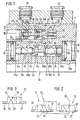
- the directional valve 10 disc-shaped housing 11 with two one above the other arranged switching valves 12, 13. These switching valves 12, 13 are provided with valve spools 14, 16 which in Recesses 18, 20 are movably guided.
- the first Valve slide 14 associated first recess 18 is as Through hole executed, the inside diameter is discontinued several times, with the two outside End regions 18a of the through hole each the largest Have inside diameter.
- the one between the two end areas 18a lying section of the recess 18 is in a relatively long slide area 18b and one shorter, smaller inside diameter guide area 18c divided.
- Support rings 22 pressed in at an axial distance from one another. to correct mounting of the support rings 22 can Slider region 18b in diameter to be Form stop edges for these support rings 22.
- the inner surfaces of the support rings 22 act as sealing surfaces for sealing rings 24 on the circumference of the first valve spool 14 are arranged.
- This valve slide 14 thus limits together with the support rings 22 and the wall of the Through hole 18 three adjacent pressure chambers 26a-c, with pressure medium connections between two adjacent pressure chambers 26 through the Valve slide 14 released depending on its switching position or be closed.
- valve spool 14 is in two piston sections 14a and 14b and a constriction 14c, the two Piston sections 14a, b interconnected, structured.
- the middle pressure chamber 26b is an external one Pressure medium channel 32, of which only the in Figure 1 Mouth cross section is recognizable with a first Working port 34 of the directional control valve 10 connected.
- the return 28 and the inlet 30 run perpendicular to Recess 18 and end on the two side surfaces of the disc-shaped housing 11. This can be done with appropriately trained, adjacent housings (not drawn) to valve blocks, which are connected by means of a common supply and return 30, 28 with pressure medium or disposed of.
- the two working connections 34, 35 of the directional valve 10 on a common end face of the Housing 11 provided.
- they are as Plug connections for plastic pipes and on the the second switching valve 13 facing the end of the Housing 11 placed.
- the valve spool 14 is in two switching positions in which the first working port 34 either is coupled to the inlet 30 or the return 28.
- the Switching process is exemplary in the embodiment of Piston 36, 37 causes the in the end regions 18a Recess 18 are guided and the two End faces of the valve spool 14 act.
- the End regions 18a accordingly form together with the pistons 36, 37 two counter-acting cylinder units, the can be pressurized externally. alternative this can be done by actuating the valve slide 14 of course also on mechanical or done electromechanical way.
- Reset devices for the valve spool 14 are not provided, so that the respective switching position of the switching valve 12 also after Elimination of the pressurization of one of the pistons 36, 37 remains. Accordingly, it is the described switching valve 12 to a conventional in itself well-known, bistable 3/2-way slide valve.
- the switching valve 12 described is pneumatic with the second switching valve 13 coupled as a monostable Flat seat valve is designed in 3/2-way construction.
- the latter is in the parallel to the recess 18
- Recess 20 housed as a blind hole is executed.
- the blind hole is towards the surroundings pressure-tight by means of a pressed-in stopper 38 locked.
- In the recess 20 are two axially spaced-in annular body 40 pressed in, the interior, as in the case of the switching valve 12, in three Subdivide adjacent pressure chambers 42a-c. Interactions between these pressure chambers 42a-c controlled by valve spool 16.
- Whose plug 38 facing, first end forms an actuating piston 43, which is delimited on the circumference by a lip sealing element 44 is.
- the second end opposite the actuating piston 43 of the valve slide 16 has a support collar 46 on which a return spring 48 is present. This is based on the bottom of the recess 20 and sets the second switching valve 13 in its depressurized state to the basic position back.
- A acts as a valve member of this second switching valve 13
- Seat body 50 which is fixed to the valve slide 16.
- the Seat body 50 forms together with the side surfaces one of the two ring bodies 40 two each other opposed flat seat valves 51a, b.
- Flat seat valves 51a, b are characterized by their low-friction operation and their good tightness.
- the second switching valve 13 is pneumatic pressure medium channels 52, 54, 56 on the housing side with the first Switch valve 12 connected.
- the first pressure medium channel 52 connects the return side pressure chamber 26a of the first Switch valve 12 with the side of the actuating piston 43 limited pressure chamber 42a of the second switching valve 13, while the second pressure medium channel 54 from the inlet-side pressure chamber 26c of the first switching valve 12 to the pressure chamber facing away from the actuating piston 43 42c of the second switching valve 13 leads.
- the return spring 48 is also located in the pressure chamber 42c.
- the middle pressure chamber 42b is in communication with the second working port 35 of the directional valve 10 and the Cylinder chamber of the actuating piston 43 is over the third pressure channel 56 with the first working port 34 acting medium pressure chamber 26b of the first Switching valve 12 connected in parallel.
- the switch symbol shown on the left in FIG. 2 represents this that connected to the first working connection 34, as Executed slide valve, first switching valve 12 and that right switching symbol that the second working connection 35th Controlling, spring-loaded second switching valve 13 in Flat seat design.
- Both switching valves 12 and 13 can assume two switch positions and each have three Connections, namely the inlet 30, the return 28 and the Working port 34 or 35.
- the first switching valve 12 is closed its actuation externally, in particular by the piston 36 and 37, controllable while the second switching valve 13 by the actuating piston 43 from the pressure level at the first Working port 34 controlled and by the return spring 48th is returned to its basic position.
- the directional control valve 10 is switched over by a Pressure pulse on the drawn in the deflected position first piston 36 of the first switching valve 12.
- the by this Piston 36 generated pressure force moves the valve spool 14 in Figure 1 to the right, making the first work port 34 charged with inlet pressure and separated from the return 28 becomes.
- the inlet pressure passes through the pressure medium channel 56 into the cylinder chamber of the actuating piston 43 of the second Switch valve 13 and deflects its valve spool 16 counter the force of the return spring 48. So far closed first flat seat valve 51a is opened and that opposite second flat seat valve 51b closed, whereby the second working connection 35 to the return 28 is relieved and blocked from the inlet 30.
- the actuating piston 43 of the second switching valve 13 via the pressure medium channel 56 also then supplied with high pressure when the first piston 36 of the switching valve 12 no longer acts at all.
- a changeover of the directional valve 10 to the first Working connection 34 again with the return 28 and the second working connection 35 again with the inlet 30 connect, is by a pressure pulse on the second Actuating piston 37 of the first switching valve 12 possible.
- the switching valve 10 accordingly has two bistable Switch positions.
- the switching symbol for the directional valve 10 described as The structural unit is drawn in FIG. 3. Accordingly, that represents Directional control valve 10 one valve with four connections - two Work connections 34, 35, an inlet 30 and one Return 28 - represents that of the externally controlled pistons 36 and 37 can be brought into two switching positions. In these two switch positions are the working connections 34, 35 alternately with the inlet 30 or the return 28 coupled.
- the directional control valve 10 is reversed by outside, for example by pressure impulses on the two Actuating pistons 36, 37; Reset devices are not present, so that there are two bistable switching positions acts, which receive even after the control pulses are no longer available stay.
Landscapes
- Engineering & Computer Science (AREA)
- Physics & Mathematics (AREA)
- Fluid Mechanics (AREA)
- Mechanical Engineering (AREA)
- General Engineering & Computer Science (AREA)
- Multiple-Way Valves (AREA)
- Fluidized-Bed Combustion And Resonant Combustion (AREA)
Description
- Die Figur 1
- zeigt ein erfindungegemäßes Wegeventil im Längsschnitt,
- in Figur 2
- sind, zur Beschreibung der Funktionen des Wegeventils, die Schaltsymbole der Einzelkomponenten dargestellt;
- Figur 3
- zeigt ein Schaltsymbol, das die Funktionsweise des erfindungsgemäßen Wegeventils als Baueinheit verdeutlicht.
Claims (9)
- Impulsgesteuertes, pneumatisches 4/2-Wegeventil (10), insbesondere zur Ansteuerung doppeltwirkender Verbraucher, mit einem Gehäuse (11), das neben Steueranschlüssen wenigstens einen Rücklauf (28), zwei Arbeitsanschlüsse (34, 35) und einen Zulauf (30) aufweist und mit einer Ventilanordnung (12, 13), die durch Ansteuerimpulse in zwei bistabile Schaltstellungen, in denen die Arbeitsanschlüsse (34, 35) wechselweise mit dem Zulauf (30) oder dem Rücklauf (28) verbunden sind, umschaltbar ist, dadurch gekennzeichnet, daß die Ventilanordnung zwei pneumatisch miteinander verschaltete 3/2-Schaltventile (12, 13) umfaßt, wobei das erste 3/2-Schaltventil (12) als bistabiles Schieberventil und das zweite 3/2-Schaltventil (13) als monostabiles Sitzventil ausgebildet ist.
- Impulsgesteuertes, pneumatisches 4/2-Wegeventil nach Anspruch 1, dadurch gekennzeichnet, daß die beiden 3/2-Schaltventile (12, 13) jeweils einem der Arbeitsanschlüsse (34, 35) des Wegeventils (10) zugeordnet sind und daß der dem ersten Schaltventil (12) zugeordnete Arbeitsanschluß (34) parallelgeschaltet mit dem Steueranschluß des zweiten Schaltventils (13) ist.
- Impulsgesteuertes, pneumatisches 4/2-Wegeventil nach einem der Ansprüche 1 oder 2, dadurch gekennzeichnet, daß das zweite Schaltventil (13) eine Druckfeder (48) umfaßt, die das zweite Schaltventil (13) nach erfolgter Ansteuerung in seine Grundstellung zurückstellt.
- Impulsgesteuertes, pneumatisches 4/2-Wegeventil nach einem der Ansprüche 1 bis 3, dadurch gekennzeichnet, daß das erste Schaltventil (12) extern ansteuerbar ist.
- Impulsgesteuertes, pneumatisches 4/2-Wegeventil nach einem der Ansprüche 1 bis 4, dadurch gekennzeichnet, daß die beiden Schaltventile (12, 13) nebeneinanderliegend in Ausnehmungen (18, 20) des Gehäuses (11) angeordnet sind und daß die beiden Ausnehmungen (18, 20) im wesentlichen parallel zueinander verlaufen.
- Impulsgesteuertes, pneumatisches 4/2-Wegeventil nach einem der Ansprüche 1 bis 5, dadurch gekennzeichnet, daß das zweite Schaltventil (13) als Flachsitzventil ausgebildet ist.
- Impulsgesteuertes, pneumatisches 4/2-Wegeventil nach einem der Ansprüche 1 bis 6, dadurch gekennzeichnet, daß zur Ver- bzw. Entsorgung des Wegeventils (10) mit Druckmittel der wenigstens eine Rücklauf (28) und der Zulauf (30) als Durchgangsausnehmungen ausgeführt sind, die jeweils an gegenüberliegenden Seitenflächen des Gehäuses (11) entspringen bzw. enden und die in Druckkammern (46a und 46b) des ersten Schaltventils (12) einmünden und daß sich die Arbeitsanschlüsse (34, 35) annähernd rechtwinklig zum Rück- bzw. Zulauf (28, 30) an einer gemeinsamen Stirnseite des Gehäuses (11) befinden.
- Impulsgesteuertes, pneumatisches 4/2-Wegeventil nach Anspruch 7, dadurch gekennzeichnet, daß dessen Gehäuse (11) scheibenförmig ausgebildet ist und mittels benachbarten Ventilgehäusen zu gemeinsam mit Druckmittel ver- bzw. entsorgten Ventilblöcken verbindbar ist.
- Impulsgesteuertes, pneumatisches 4/2-Wegeventil nach einem der Ansprüche 1 bis 8, dadurch gekennzeichnet, daß in der Grundstellung des Wegeventils (10) die beiden Schaltventile (12, 13) derart gekoppelt sind, daß das erste Schaltventil (12) den ersten Arbeitsanschluß (34) zum Rücklauf (28) entlastet und den Zulauf (30) absperrt, während das zweite Schaltventil (13) den zweiten Arbeitsanschluß (35) mit dem Zulauf (30) verbindet und den Rücklauf (28) sperrt und daß diese Beschaltung des Wegeventils (10) durch Steuerimpulse umkehrbar ist.
Applications Claiming Priority (3)
| Application Number | Priority Date | Filing Date | Title |
|---|---|---|---|
| DE19841056 | 1998-09-09 | ||
| DE19841056A DE19841056A1 (de) | 1998-09-09 | 1998-09-09 | Impulsgesteuertes pneumatisches 4/2-Wegeventil |
| PCT/DE1999/002580 WO2000014414A1 (de) | 1998-09-09 | 1999-08-17 | Impulsgesteuertes pneumatisches 4/2-wegeventil |
Publications (2)
| Publication Number | Publication Date |
|---|---|
| EP1042616A1 EP1042616A1 (de) | 2000-10-11 |
| EP1042616B1 true EP1042616B1 (de) | 2002-11-06 |
Family
ID=7880268
Family Applications (1)
| Application Number | Title | Priority Date | Filing Date |
|---|---|---|---|
| EP99952432A Expired - Lifetime EP1042616B1 (de) | 1998-09-09 | 1999-08-17 | Impulsgesteuertes pneumatisches 4/2-wegeventil |
Country Status (5)
| Country | Link |
|---|---|
| EP (1) | EP1042616B1 (de) |
| JP (1) | JP2002524697A (de) |
| DE (2) | DE19841056A1 (de) |
| HU (1) | HU224252B1 (de) |
| WO (1) | WO2000014414A1 (de) |
Cited By (1)
| Publication number | Priority date | Publication date | Assignee | Title |
|---|---|---|---|---|
| CN101915183A (zh) * | 2010-07-01 | 2010-12-15 | 北京航空航天大学 | 双工况阶跃式流量控制阀及控制结构设计方法 |
Families Citing this family (3)
| Publication number | Priority date | Publication date | Assignee | Title |
|---|---|---|---|---|
| DE10301119C5 (de) | 2003-01-14 | 2018-04-05 | Wabco Gmbh | Luftfederungssystem |
| CN108488125B (zh) * | 2018-03-21 | 2019-12-17 | 洛阳世英机械制造有限公司 | 一种多功能手电一体旋转式控制阀 |
| CN110522982B (zh) * | 2019-09-26 | 2024-02-20 | 泰州市久信医疗科技有限公司 | 一种单输入双输出气体流量调节装置 |
Family Cites Families (7)
| Publication number | Priority date | Publication date | Assignee | Title |
|---|---|---|---|---|
| GB1012961A (en) * | 1963-10-28 | 1965-12-15 | Hamilton Controllers Ltd | Improvements in pneumatic control valves |
| DE2510151A1 (de) * | 1975-03-08 | 1976-09-09 | Knorr Bremse Gmbh | 4/2-wege-steuerventil |
| FR2328147A1 (fr) * | 1975-10-17 | 1977-05-13 | Reolon Noe | Distributeur a trois voies pour fluide de commande |
| DE3107012A1 (de) * | 1981-02-25 | 1982-11-04 | Bochumer Eisenhütte Heintzmann GmbH & Co, 4630 Bochum | Schieberventil fuer oel-in-wasser-emulsionen |
| DE3216809A1 (de) * | 1982-05-05 | 1983-11-10 | Robert Bosch Gmbh, 7000 Stuttgart | Wegeventil, das fuer unterschiedliche betriebsarten vorgesehen ist |
| DE4400760C2 (de) * | 1994-01-13 | 1997-03-27 | Festo Kg | Mehrwegeventil |
| DE19649833A1 (de) * | 1996-12-02 | 1998-06-04 | Bosch Gmbh Robert | Elektrohydraulische Steuervorrichtung |
-
1998
- 1998-09-09 DE DE19841056A patent/DE19841056A1/de not_active Withdrawn
-
1999
- 1999-08-17 JP JP2000569131A patent/JP2002524697A/ja not_active Withdrawn
- 1999-08-17 WO PCT/DE1999/002580 patent/WO2000014414A1/de not_active Ceased
- 1999-08-17 HU HU0100339A patent/HU224252B1/hu not_active IP Right Cessation
- 1999-08-17 EP EP99952432A patent/EP1042616B1/de not_active Expired - Lifetime
- 1999-08-17 DE DE59903313T patent/DE59903313D1/de not_active Expired - Fee Related
Cited By (1)
| Publication number | Priority date | Publication date | Assignee | Title |
|---|---|---|---|---|
| CN101915183A (zh) * | 2010-07-01 | 2010-12-15 | 北京航空航天大学 | 双工况阶跃式流量控制阀及控制结构设计方法 |
Also Published As
| Publication number | Publication date |
|---|---|
| EP1042616A1 (de) | 2000-10-11 |
| HU224252B1 (hu) | 2005-07-28 |
| HUP0100339A3 (en) | 2001-11-28 |
| JP2002524697A (ja) | 2002-08-06 |
| WO2000014414A1 (de) | 2000-03-16 |
| DE19841056A1 (de) | 2000-03-23 |
| DE59903313D1 (de) | 2002-12-12 |
| HUP0100339A2 (hu) | 2001-06-28 |
Similar Documents
| Publication | Publication Date | Title |
|---|---|---|
| DE2543466C3 (de) | Fluidgesteuertes Ventil | |
| DE4400760C2 (de) | Mehrwegeventil | |
| EP0066274B1 (de) | Ventilanordnung zur Erhöhung der Ausfahrgeschwindigkeit eines Arbeitszylinders | |
| DE2112813C3 (de) | Elektrohydraulische Steuereinrichtung | |
| DE2509712A1 (de) | Einrichtung fuer die steuerung eines fluidums | |
| DE4234626C2 (de) | Druckgesteuertes Ventil | |
| EP0110126B1 (de) | Elektromagnetisch betätigtes Wegeventil | |
| EP0687818B1 (de) | Pneumatisches Wegeventil | |
| DE10114472A1 (de) | Elektromagnet zum Antrieb eines hydraulischen Ventils | |
| DE4436548C2 (de) | Ventilanordnung zur Betätigung eines hydraulischen Verbrauchers | |
| DE3000260C2 (de) | ||
| DE19649833A1 (de) | Elektrohydraulische Steuervorrichtung | |
| DE3315056C2 (de) | Elektrohydraulisches Mehrwege-Regelventil | |
| DE19841056A1 (de) | Impulsgesteuertes pneumatisches 4/2-Wegeventil | |
| EP0342409A2 (de) | Sicherheitsventil | |
| DE19509578B4 (de) | Pneumatisches Wegeventil | |
| DE3207571C2 (de) | Doppeltwirkender, in den Endlagen selbsttätig umsteuernder hydraulischer Druckwandler | |
| DE4020024A1 (de) | Elektromagnetisch betaetigbares wegeventil | |
| DE19932139B4 (de) | Vorgesteuertes Schieberventil | |
| DE19909918A1 (de) | Vorsteuerbares Wegeventil | |
| DE4418514B4 (de) | Elektrohydraulisches Wegeventil | |
| EP0618372B1 (de) | Hydraulische Steuereinrichtung mit mindestens einem hydraulisch entsperrbaren Rückschlagventil | |
| DE3332207C2 (de) | Doppeltwirkender, in seinen beiden Endlagen selbsttätig umsteuernder Druckwandler | |
| DE1917885A1 (de) | Fluidbetaetigte Einrichtung mit beweglichem Kolben | |
| EP0005818B1 (de) | Hydraulisch betätigtes 3-Wegesitzventil |
Legal Events
| Date | Code | Title | Description |
|---|---|---|---|
| PUAI | Public reference made under article 153(3) epc to a published international application that has entered the european phase |
Free format text: ORIGINAL CODE: 0009012 |
|
| AK | Designated contracting states |
Kind code of ref document: A1 Designated state(s): AT BE CH CY DE DK ES FI FR GB GR IE IT LI LU MC NL PT SE |
|
| 17P | Request for examination filed |
Effective date: 20000918 |
|
| GRAG | Despatch of communication of intention to grant |
Free format text: ORIGINAL CODE: EPIDOS AGRA |
|
| GRAG | Despatch of communication of intention to grant |
Free format text: ORIGINAL CODE: EPIDOS AGRA |
|
| GRAH | Despatch of communication of intention to grant a patent |
Free format text: ORIGINAL CODE: EPIDOS IGRA |
|
| 17Q | First examination report despatched |
Effective date: 20020308 |
|
| GRAH | Despatch of communication of intention to grant a patent |
Free format text: ORIGINAL CODE: EPIDOS IGRA |
|
| GRAA | (expected) grant |
Free format text: ORIGINAL CODE: 0009210 |
|
| AK | Designated contracting states |
Kind code of ref document: B1 Designated state(s): CH DE FR GB LI |
|
| REG | Reference to a national code |
Ref country code: GB Ref legal event code: FG4D Free format text: NOT ENGLISH |
|
| REG | Reference to a national code |
Ref country code: CH Ref legal event code: EP |
|
| REG | Reference to a national code |
Ref country code: IE Ref legal event code: FG4D Free format text: GERMAN |
|
| REF | Corresponds to: |
Ref document number: 59903313 Country of ref document: DE Date of ref document: 20021212 |
|
| GBT | Gb: translation of ep patent filed (gb section 77(6)(a)/1977) |
Effective date: 20030122 |
|
| ET | Fr: translation filed | ||
| REG | Reference to a national code |
Ref country code: IE Ref legal event code: FD4D Ref document number: 1042616E Country of ref document: IE |
|
| PG25 | Lapsed in a contracting state [announced via postgrant information from national office to epo] |
Ref country code: LI Free format text: LAPSE BECAUSE OF NON-PAYMENT OF DUE FEES Effective date: 20030831 Ref country code: CH Free format text: LAPSE BECAUSE OF NON-PAYMENT OF DUE FEES Effective date: 20030831 |
|
| PLBE | No opposition filed within time limit |
Free format text: ORIGINAL CODE: 0009261 |
|
| STAA | Information on the status of an ep patent application or granted ep patent |
Free format text: STATUS: NO OPPOSITION FILED WITHIN TIME LIMIT |
|
| 26N | No opposition filed |
Effective date: 20030807 |
|
| REG | Reference to a national code |
Ref country code: CH Ref legal event code: PL |
|
| PGFP | Annual fee paid to national office [announced via postgrant information from national office to epo] |
Ref country code: GB Payment date: 20040730 Year of fee payment: 6 |
|
| PG25 | Lapsed in a contracting state [announced via postgrant information from national office to epo] |
Ref country code: GB Free format text: LAPSE BECAUSE OF NON-PAYMENT OF DUE FEES Effective date: 20050817 |
|
| GBPC | Gb: european patent ceased through non-payment of renewal fee |
Effective date: 20050817 |
|
| PGFP | Annual fee paid to national office [announced via postgrant information from national office to epo] |
Ref country code: DE Payment date: 20070822 Year of fee payment: 9 |
|
| PGFP | Annual fee paid to national office [announced via postgrant information from national office to epo] |
Ref country code: FR Payment date: 20080818 Year of fee payment: 10 |
|
| PG25 | Lapsed in a contracting state [announced via postgrant information from national office to epo] |
Ref country code: DE Free format text: LAPSE BECAUSE OF NON-PAYMENT OF DUE FEES Effective date: 20090303 |
|
| REG | Reference to a national code |
Ref country code: FR Ref legal event code: ST Effective date: 20100430 |
|
| PG25 | Lapsed in a contracting state [announced via postgrant information from national office to epo] |
Ref country code: FR Free format text: LAPSE BECAUSE OF NON-PAYMENT OF DUE FEES Effective date: 20090831 |