EP1037954B1 - Entfernbares klebebandlaminat und trennbares befestigungsmittel - Google Patents
Entfernbares klebebandlaminat und trennbares befestigungsmittel Download PDFInfo
- Publication number
- EP1037954B1 EP1037954B1 EP98923354A EP98923354A EP1037954B1 EP 1037954 B1 EP1037954 B1 EP 1037954B1 EP 98923354 A EP98923354 A EP 98923354A EP 98923354 A EP98923354 A EP 98923354A EP 1037954 B1 EP1037954 B1 EP 1037954B1
- Authority
- EP
- European Patent Office
- Prior art keywords
- adhesive
- adhesive tape
- layer
- backing layer
- connector
- Prior art date
- Legal status (The legal status is an assumption and is not a legal conclusion. Google has not performed a legal analysis and makes no representation as to the accuracy of the status listed.)
- Expired - Lifetime
Links
Images
Classifications
-
- A—HUMAN NECESSITIES
- A47—FURNITURE; DOMESTIC ARTICLES OR APPLIANCES; COFFEE MILLS; SPICE MILLS; SUCTION CLEANERS IN GENERAL
- A47G—HOUSEHOLD OR TABLE EQUIPMENT
- A47G1/00—Mirrors; Picture frames or the like, e.g. provided with heating, lighting or ventilating means
- A47G1/16—Devices for hanging or supporting pictures, mirrors, or the like
- A47G1/17—Devices for hanging or supporting pictures, mirrors, or the like using adhesives, suction or magnetism
- A47G1/175—Stretch releasing adhesives
-
- C—CHEMISTRY; METALLURGY
- C09—DYES; PAINTS; POLISHES; NATURAL RESINS; ADHESIVES; COMPOSITIONS NOT OTHERWISE PROVIDED FOR; APPLICATIONS OF MATERIALS NOT OTHERWISE PROVIDED FOR
- C09J—ADHESIVES; NON-MECHANICAL ASPECTS OF ADHESIVE PROCESSES IN GENERAL; ADHESIVE PROCESSES NOT PROVIDED FOR ELSEWHERE; USE OF MATERIALS AS ADHESIVES
- C09J7/00—Adhesives in the form of films or foils
- C09J7/20—Adhesives in the form of films or foils characterised by their carriers
-
- C—CHEMISTRY; METALLURGY
- C09—DYES; PAINTS; POLISHES; NATURAL RESINS; ADHESIVES; COMPOSITIONS NOT OTHERWISE PROVIDED FOR; APPLICATIONS OF MATERIALS NOT OTHERWISE PROVIDED FOR
- C09J—ADHESIVES; NON-MECHANICAL ASPECTS OF ADHESIVE PROCESSES IN GENERAL; ADHESIVE PROCESSES NOT PROVIDED FOR ELSEWHERE; USE OF MATERIALS AS ADHESIVES
- C09J2301/00—Additional features of adhesives in the form of films or foils
- C09J2301/10—Additional features of adhesives in the form of films or foils characterized by the structural features of the adhesive tape or sheet
- C09J2301/12—Additional features of adhesives in the form of films or foils characterized by the structural features of the adhesive tape or sheet by the arrangement of layers
- C09J2301/124—Additional features of adhesives in the form of films or foils characterized by the structural features of the adhesive tape or sheet by the arrangement of layers the adhesive layer being present on both sides of the carrier, e.g. double-sided adhesive tape
-
- C—CHEMISTRY; METALLURGY
- C09—DYES; PAINTS; POLISHES; NATURAL RESINS; ADHESIVES; COMPOSITIONS NOT OTHERWISE PROVIDED FOR; APPLICATIONS OF MATERIALS NOT OTHERWISE PROVIDED FOR
- C09J—ADHESIVES; NON-MECHANICAL ASPECTS OF ADHESIVE PROCESSES IN GENERAL; ADHESIVE PROCESSES NOT PROVIDED FOR ELSEWHERE; USE OF MATERIALS AS ADHESIVES
- C09J2301/00—Additional features of adhesives in the form of films or foils
- C09J2301/30—Additional features of adhesives in the form of films or foils characterized by the chemical, physicochemical or physical properties of the adhesive or the carrier
- C09J2301/308—Additional features of adhesives in the form of films or foils characterized by the chemical, physicochemical or physical properties of the adhesive or the carrier the adhesive tape or sheet losing adhesive strength when being stretched, e.g. stretch adhesive
-
- Y—GENERAL TAGGING OF NEW TECHNOLOGICAL DEVELOPMENTS; GENERAL TAGGING OF CROSS-SECTIONAL TECHNOLOGIES SPANNING OVER SEVERAL SECTIONS OF THE IPC; TECHNICAL SUBJECTS COVERED BY FORMER USPC CROSS-REFERENCE ART COLLECTIONS [XRACs] AND DIGESTS
- Y10—TECHNICAL SUBJECTS COVERED BY FORMER USPC
- Y10T—TECHNICAL SUBJECTS COVERED BY FORMER US CLASSIFICATION
- Y10T24/00—Buckles, buttons, clasps, etc.
- Y10T24/20—Paper fastener
- Y10T24/207—Adhesive
-
- Y—GENERAL TAGGING OF NEW TECHNOLOGICAL DEVELOPMENTS; GENERAL TAGGING OF CROSS-SECTIONAL TECHNOLOGIES SPANNING OVER SEVERAL SECTIONS OF THE IPC; TECHNICAL SUBJECTS COVERED BY FORMER USPC CROSS-REFERENCE ART COLLECTIONS [XRACs] AND DIGESTS
- Y10—TECHNICAL SUBJECTS COVERED BY FORMER USPC
- Y10T—TECHNICAL SUBJECTS COVERED BY FORMER US CLASSIFICATION
- Y10T24/00—Buckles, buttons, clasps, etc.
- Y10T24/27—Buckles, buttons, clasps, etc. including readily dissociable fastener having numerous, protruding, unitary filaments randomly interlocking with, and simultaneously moving towards, mating structure [e.g., hook-loop type fastener]
- Y10T24/2708—Combined with diverse fastener
-
- Y—GENERAL TAGGING OF NEW TECHNOLOGICAL DEVELOPMENTS; GENERAL TAGGING OF CROSS-SECTIONAL TECHNOLOGIES SPANNING OVER SEVERAL SECTIONS OF THE IPC; TECHNICAL SUBJECTS COVERED BY FORMER USPC CROSS-REFERENCE ART COLLECTIONS [XRACs] AND DIGESTS
- Y10—TECHNICAL SUBJECTS COVERED BY FORMER USPC
- Y10T—TECHNICAL SUBJECTS COVERED BY FORMER US CLASSIFICATION
- Y10T428/00—Stock material or miscellaneous articles
- Y10T428/14—Layer or component removable to expose adhesive
- Y10T428/1481—Dissimilar adhesives
-
- Y—GENERAL TAGGING OF NEW TECHNOLOGICAL DEVELOPMENTS; GENERAL TAGGING OF CROSS-SECTIONAL TECHNOLOGIES SPANNING OVER SEVERAL SECTIONS OF THE IPC; TECHNICAL SUBJECTS COVERED BY FORMER USPC CROSS-REFERENCE ART COLLECTIONS [XRACs] AND DIGESTS
- Y10—TECHNICAL SUBJECTS COVERED BY FORMER USPC
- Y10T—TECHNICAL SUBJECTS COVERED BY FORMER US CLASSIFICATION
- Y10T428/00—Stock material or miscellaneous articles
- Y10T428/24—Structurally defined web or sheet [e.g., overall dimension, etc.]
- Y10T428/24008—Structurally defined web or sheet [e.g., overall dimension, etc.] including fastener for attaching to external surface
- Y10T428/24017—Hook or barb
Definitions
- the present invention relates to adhesive tape structures that can be adhered to a surface and thereafter removed without substantially damaging the surface or leaving substantial adhesive residue. More particularly, the present invention relates to a removable and separable adhesive tape product.
- laminated tape structures have been used to bond the opposed surfaces of two objects together, such as to bond a wall hanging (e.g. a poster, plaque or picture) to the surface of a wall.
- the adhesive product may comprise an easily releasable adhesive perminiting removal from a substrate surface while leaving little or no adhesive residue on the surface.
- examples include repositionable products available under the trade designation "Post-it” from Minnesota Mining and Manufacturing Company ("3M”) of St. Paul, Minnesota.
- Another type of removable adhesive tape laminate is a single-sided or double-sided adhesive tape that is stretchable to accomplish removal.
- Such an adhesive tape can have conventional pressure-sensitive adhesive on one or both major surfaces thereof, and a tape backing comprising a highly extensible material.
- the adhesive may comprise a solid adhesive material that itself provides one or two adhesive surfaces and is sufficiently extensible.
- stretch release adhesive tapes are known to be provided in strips for bonding objects together and which have a pull tab portion at the end of the strip to facilitate the stretching and debonding. Examples of such strips and tabs are described in U.S. Patent Nos. 5,409,189 to Luhmann and 5,516,581 to Kreckel et al, and in U.S. Patent Application Nos. 08/308,937 entitled “Removable Foam Adhesive Tape” filed September 20, 1994 and 08/940,555 entitled “Removable Adhesive Tape with Controlled Sequential Release” filed September 30, 1997, both to Bries et al. An article support specifically designed for use with such stretch release tapes is disclosed in U.S. Patent No. 5,507,464 to Hamerski et al. An advantage of these stretch release adhesive tapes is that they utilize conventional pressure sensitive adhesives that can provide a strong bond against shear, peel and lift-off forces. Moreover, heavier weighted objects can be supported.
- the tab With these stretch releasable tape strips, access must be provided to the tab to permit the release.
- the tab In the case where the strip is provided between an object support, e.g. a picture hook, and a surface, e.g. a wall, the tab can be provided easily where the support and exposed tab will be covered by the object (such as a picture) to be supported thereon. Also, with object supports, such as a picture hook, the hook can be reusable by providing a new tape strip. If, however, it is desirable to directly connect an object (such as a picture) to a substrate (such as a wall) by a stretch releasable strip, the tab needs to extend out from between the opposed surfaces to provide access. In many cases, this can provide an objectionable appearance.
- a tape laminate structure having an internally separable layer, which is described in co-pending U.S. Patent Application Serial No. 08/746,351 entitled “Internally Separable Tape Laminate” filed November 8, 1996.
- a tape structure is provided that can be used to bond together the opposed surfaces of objects with no portion of the tape structure projecting from between the objects and which permits separation of the objects.
- the tape structure comprises an internally separable layer provided between one or two stretch releasable tape strips.
- each layer portion can be removed from its respective object by pulling a stretch release tab. Since the stretch release tabs are only needed after separation of the internal layer, they can easily be positioned to be hidden when the objects are secured together. However, once the objects are separated from another, which causes the internal layer to be broken apart, the objects cannot be reconnected with one another unless a new separable tape structure (or other type of product) is used.
- Reusable connectors of many types are also commonly known, with particular types being more suited for specific different applications than others.
- Reusable fasteners include mechanical type fasteners, such as hook and loop systems (e.g. hook and loop products available under the trade designation "Velcro” and those commercially available under the trade designation “3M Scotchmate” industrial fastener, from Minnesota Mining and Manufacturing Company (“3M”) of St. Paul, Minnesota), other mechanical interlocking fasteners, such as described in U.S. Patent No. 5,077,870 to Melbye et al, and intermeshing fasteners (having connection without macroscopic mechanical deformation or interference), such as described in U.S. Patent No. 4,875,259 to Appeldorn.
- mechanical type fasteners such as hook and loop systems (e.g. hook and loop products available under the trade designation "Velcro” and those commercially available under the trade designation “3M Scotchmate” industrial fastener, from Minnesota Mining and Manufacturing Company (“3M”) of St.
- reusable fasteners include releasable contact responsive fasteners, such as described in PCT International Publication No. WO 94/21742 or PCT International Publication No. WO 96/24535.
- Contact responsive fasteners include a non-tacky layer and a target layer to which the non-tacky layer can bond.
- Contact responsive polymer layers are more readily able to bond to materials having similar solubility parameters, and when the solubility parameters of the target layer and the contact responsive polymer layer are sufficiently close, the degree of interaction between these materials is enhanced and bond formation is promoted.
- fastener systems are also known to be provided with adhesive on their respective non-connector side surfaces for bonding to the objects which are to be connected.
- the hook side of a hook and loop system may be adhered to one object while the loop side is adhered to another object.
- these fastener systems permit the separation of one object from another, each of the objects retains its portion of the fastener system, which are not easily removable.
- the present invention overcomes the disadvantages and shortcomings of the prior art by providing an adhesive tape construction that is removable from one or more objects to which it is adhered and which is reusably separable within its construction so that the objects can be separated from one another and subsequently reconnected with one another.
- the present invention provides an adhesive tape construction that can be used to bond the other opposed surfaces of objects, including rigid objects such as a picture frame to a wall, where no portion of the adhesive tape construction projects from between the objects, and which subsequently affords easy separation of the objects without damage to either of them.
- the adhesive tape construction includes a stretch release adhesive tape structure combined with a reusable connector surface.
- an adhesive tape for attaching plural objects to one another comprising at least one stretchable backing layer having first and second major surfaces and first and second ends, an adhesive surface over at least a portion of the first major surface of the backing layer for bonding to a surface of an object, and a separable connector surface covering at least a portion of the second major surface of the backing layer.
- the backing layer and adhesive surface may be provided by a single solid adhesive layer or may comprise a separate backing layer combined with an adhesive layer.
- the backing layer and adhesive surface are stretchable together to effect progressive debonding of the adhesive layer from an object after the adhesive surface is bonded to that object by the application of a force to the first end of the backing layer in a direction of extension of the backing layer between its first and second ends.
- the separable connector surface possesses the ability to be connected, disconnected and reconnected to a cooperating connection surface without destruction of the separable connection surface and/or the adhesive tape.
- a second backing layer is also provided having first and second major surfaces and first and second ends, an adhesive surface over at least a portion of its first major surface for bonding to a surface of another object, and a cooperating separable connector surface covering at least a portion of the second major surface of the second backing layer.
- the second backing layer and adhesive surface may be provided by a single solid adhesive layer or may comprise a separate backing layer combined with an adhesive layer.
- the second backing layer and its adhesive surface are stretchable together to effect progressive debonding of the adhesive surface from the other object after its adhesive surface is bonded to that object by the application of a force to the first end of the second backing layer in a direction of extension of the second backing layer between its first and second ends and the cooperating separable connector surface possesses the ability to be connected, disconnected and reconnected to the connection surface of the first backing layer without destruction of the separable connection surface, the cooperating connection surface and the adhesive tape.
- the separable connection and cooperating separable connection surfaces can be provided in any number of different ways depending on the particular application and the desirable characteristics for that application. Interlocking mechanical connector systems, intermeshing connector systems, contact responsive fasteners, magnet, and low-tack adhesives are but a few examples of suitable connector systems.
- the present invention is also directed to the combination of the aforementioned tape constructions with a plurality of objects.
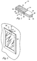
- The. tape construction is particularly applicable for the joining of an object to a vertical surface (for example, a picture frame to a wall), but can be used in any number of bonding applications.
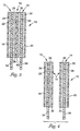
- the adhesive tape 10 comprises a first stretch release adhesive tape structure 12 and a second stretch release adhesive tape structure 14 connected together by a separable connector system 16.
- one of the first or second stretch release adhesive tape structures may be replaced with a non-stretch release adhesive, for example, a pressure-sensitive adhesive or an epoxy adhesive, in embodiments where a more permanent adhesion on one side of the tape is desired.
- the adhesive tape 10 can be positioned between a first object 50 (a wall) and a second object 52 (a picture frame) without any portion of the adhesive tape 10 extending out from in between the first and second objects 50 and 52.
- the picture frame is shown connected by a single adhesive tape 10 positioned to provide a balanced support to the wall; however, any number of adhesive tapes 10 can be used.
- the ability to reposition the objects together is facilitated to allow for accurate alignment and balanced positioning.
- first stretch release adhesive structure 12 is connected with the second stretch release adhesive tape structure 14 by the separable connector system 16 and with a first liner 18 covering one side of the adhesive tape 10 and a second liner 20 covering the other side of the adhesive tape 10.
- Liners 18 and 20 may comprise any conventional or developed material, such as a silicone release paper, for covering adhesive and which can be easily removed to provide subsequent bonding of adhesive to an object.
- the first stretch release adhesive structure 12 comprises a backing layer 22 and adhesive layers 24 and 26 of the same or different pressure-sensitive adhesive compositions on opposite major surfaces of the backing layer 22.
- the thicknesses of the layers of the Figures are not to scale with respect to one another.
- Second stretch release adhesive structure 14 likewise comprises a backing layer 28 and adhesive layers 30 and 32 of the same or different pressure-sensitive adhesive compositions on opposite major surfaces of the backing layer 28.
- the external surfaces of the adhesive layers 24 and 32 of the first and second stretch release adhesive tape structures 12 and 14, respectively, are covered by the liners 18 and 20, respectively.
- the backing layers 22 and 28, as illustrated, comprise a stretchable polymeric foam layer.
- the backing layers 22 and 28 can alternatively comprise a stretchable polymeric film layer.
- the choice of polymeric foam or polymeric film depends on the specific application for the adhesive tape 10. Polymeric foams can be chosen to optimize conformability and resiliency properties which are helpful when the adhesive tape 10 is to be adhered to surfaces having surface irregularities. Such is the case with a typical wall surface. Polymeric films may be used instead to increase load bearing strength and rupture strength of the tapes; however, tapes are more suitable when the application is to adhere two very smooth surfaces together. Combinations of foams and films are contemplated as well, as is further described below. Suitable polymeric foams and films and combinations thereof are discussed in greater detail below.
- solid adhesives can be used instead of the combination of a film and/or foam with adhesive layers.
- Known stretchable solid adhesives which are generally elastic in nature and usable include rubber-based and acrylate-solid adhesives.
- a solid adhesive When using a solid adhesive as the stretchable backing, it provides not only the backing layer, but also the two adhesive layers as one.
- a solid adhesive layer may itself comprise plural material provided as sublayers or mixtures or otherwise, and may be provided in a way so that one adhesive surface is the same or different than its other adhesive surface.
- two different solid adhesives can be co-extruded so as to provide a solid adhesive layer comprising two different sublayers, one forming a first adhesive surface of a first adhesive aggressiveness and the other forming a second adhesive surface of a second adhesive aggressiveness.
- the first may be a strong adhesive, while the second could advantageously be repositionable.
- each of the first and second stretch release adhesive tape structures 12 and 14 preferably include a tab 34 and 36, respectively.
- Tabs 34 and 36 facilitate the stretch release of each adhesive tape structure 12 and 14, respectively.
- Tab 34 is preferably provided as an extension of the backing layer 12. That is, the backing layer 22 extends farther longitudinally than the adhesive layers 24 or 26.
- the tab 36 comprises an extension of the backing layer 28 that extends farther longitudinally than the adhesive layers 30 and 32.
- the adhesive layers 24, 26, 30 and 32 each cover a similar area of the backing layers 22 and 28, respectively.
- Tabs 34 and 36 can also be specifically shaped to facilitate the easy gripping thereof for the stretch release, described below. Where a solid adhesive is used, it may further be desirable to make the tab(s) non-adhesive. This can be done by any way of masking the adhesive surface or by rendering the adhesive surface non-adhesive, i.e. detackifying the adhesive surface.
- the separable connector system 16 preferably comprises a first connector component 38 and a second connector component 40.
- the first connector component 38 is bonded to the first stretch release adhesive tape structure 12 by the surface of adhesive layer 26.
- the second connector component 40 is bonded to the second stretch release adhesive tape structure 14 by the surface of adhesive layer 30.
- the first and second connector components 38 and 40 are preferably co-extensive with and cover the similar areas as the adhesive layers 24, 26, 30 and 32.
- the separable connector system 16 can comprise any known or developed reusable connector system for connecting the first and second stretch release adhesive tape structures 12 and 14 together. It is understood that connector systems may have many different properties that make them particularly suitable for certain applications or for connecting certain types of objects together. Thus, in accordance with the present invention, any such connector system can be used, but the chosen connector system can be advantageously picked based upon its properties that make it particularly suitable for a specific application or for connecting certain types of objects together.
- the separable connector system 16 permits the reusable separation and connection of the stretch release adhesive tape structures 12 and 14 along a general plane.
- the connector system 16 may comprise, for example, mechanical type fasteners, including interlocking systems, intermeshing systems (having connection without macroscopic mechanical deformation or interference), releasable contact responsive fasteners, and the like, a number of examples of which will be specifically described below.
- the stretch release adhesive tape structures 12 and 14 are separable so that the first connector component 38 remains with the first stretch release adhesive tape structure 12 and the second connector component 40 remains with the second stretch release adhesive tape structure 14 after separation of the connector system 16.
- the area of connection and the type of the separable connector system 16 should be selected so that the force required to separate the adhesive tape 10 into the first and second stretch release adhesive tape structures 12 and 14 can be readily applied by a user.
- a force may be applied in a direction substantially perpendicular to the general plane of the connector system, or as a peeling force, a cleavage force, combinations thereof or other release mechanisms.
- the type of force applied depends largely on the objects that are bonded together. With very flexible materials, a peeling force would likely be a primary force utilized for releasing the separable connector system 16.
- a cleavage force may be mostly applied; that is where a person would pull from the bottom edge of the frame (causing angular displacement) to release the separable connector system 16 of the adhesive tape 10 located at the top. If the frame were pulled to release in a perpendicular direction, a perpendicular force is applied.
- the connector system 16 should provide sufficient strength along the general plane of its separation so that, depending on the specific application, the separable connector system 16 will not separate based on the use of the adhesive tape 10 between plural objects.
- the connector system 16 In the case of an object such as a picture frame mounted to a vertical wall surface (as shown in Figure 2), the connector system 16 should be of sufficient strength in the direction of its general plane of separation so that the picture frame will not shift downward during application or over time.
- the separable connector system 16 provides an internal static shear strength in a direction parallel to the surfaces of the adhesive layers 24 and 32 for supporting the objects between which the adhesive tape 10 is attached in that direction. That is, the shear strength of the connector system 16 preferably equals or exceeds the highest shear force that the pressure sensitive adhesive can develop with surfaces to which it is applied (e.g., about six pounds per square inch (0.041 MPa)).
- the dynamic tensile force required to separate the separable connector system 16 can be up to 30, 35 or even 40 pounds per square inch (0.21, 0.24, or 0.276 MPa) without causing damage to such surfaces.
- the dynamic tensile force in the perpendicular direction required to separate the connector system 16 should be in the range of about 20 to 30 pounds per square inch (0.14 to 0.21 MPa) to restrict damages to those surfaces.
- the same concerns are preferably addressed. That is, it is desirable to provide a requisite separation force without causing damage to one or both of the adhered surfaces.
- a peel force, cleave force or combination of forces including combinations with a perpendicular lift force
- the separable connector system 16 may be separated by the application of lower force values.
- different embodiments of the adhesive tape 10 can be made with separable connector systems 16 of different types, areas of connection, or materials that require different dynamic tensile forces to separate the connector system 16 as may be appropriate for use of the adhesive tape 10 on different substrates (based on the surface composition or its finish, or the nature of the substrate, e.g. its flexibility). These different embodiments of the adhesive tape 10 can be coded by making them in different shapes and/or colors to indicate the substrates on which their use is most appropriate.
- the aggressiveness of these adhesive layers 24, 26, 30 and 32 should be chosen so that the separable connector system 16 comprising first component 38 and second component 40 separates prior to any delamination of the first or second stretch release adhesive tape structures 12 or 14 or to separation of the bond between the adhesive layers 24 and 32 with the surfaces of objects 50 and 52, respectively.
- the adhesive affinity or aggressiveness can be modified by treatments of the backing materials or surface objects. Treatments include without limitation, for example, corona discharge, plasma discharge, flame treatment, electron beam irradiation, ultraviolet radiation, chemical priming, or acid etching.
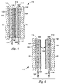
- FIG. 5 Illustrated in Figures 5 is a specific example of an adhesive tape construction 110 connected between a first object 50 and a second object 52.
- the first object 50 may be a wall, for example, to which a picture frame, for example, is attached.
- the adhesive tape 110 comprises a first stretch release adhesive tape structure 112 and a second stretch release adhesive tape structure 114.
- a separable connector system 116 connects the stretch release adhesive tape structures 112 and 114 together as shown in Figure 5.
- the first stretch release adhesive tape structure 112 comprises a backing layer 122, a first adhesive layer 124 and a second adhesive layer 126.
- the second stretch release adhesive tape structure 114 comprises backing layer 128, a first adhesive layer 130 and a second adhesive layer 132.
- Tabs 134 and 136 are provided as extensions of the backing layers 122 and 128, respectively, to facilitate stretch release of objects 50 and 52, in the manner described below.
- a first connector component comprises a layer of hook material 138 which is bonded with the first stretch release adhesive tape structure 112 at the surface of the adhesive layer 126.
- a second connector component of the separable connector system 116 comprises a layer of loop material 140 which is bonded with the second stretch release adhesive tape structure 114 at the surface of adhesive layer 130.
- the hook and loop material are interentangled thereby connecting the separable connector system 116, as conventionally known.
- any commercially available hook and loop connector system can be utilized within this embodiment, so long as the ease of separation can be accomplished in accordance with a desired force as based on a preferred application and as discussed above.
- the adhesive layers 124, 126, 130 and 132 preferably comprise conventional pressure-sensitive adhesive of the same or different types. However, the aggressiveness of these adhesive layers should be chosen so that the separable connector system 116 comprising hook material 138 and loop material 140 separates prior to any delamination of the first or second stretch release adhesive tape structures 112 or 114 or to separation of the bond between the adhesive layers 124 and 132 with the surfaces of objects 50 and 52, respectively.
- Hook and loop connector systems are but one type of mechanical interlocking connector systems which are suggested by this embodiment.
- mechanical interlocking it is meant those fasteners where at least one of the connector elements undergoes some macroscopic deformation (preferably plastic deformation) so that a mechanical interference results between plural components.
- Well known examples include hook and loop products commercially available under the trade designation "3M Scotchmate” industrial fastener, from Minnesota Mining and Manufacturing Company (“3M”) of St. Paul, Minnesota) and those hook and loop products that are commercially available under the trade designation "Velcro”.
- Many other connector systems and fasteners are known which comprise elements extending from a generally planar layer of one material to meet with similar or dissimilar cooperating members extending from another generally planar layer. Many different modifications of the interengaging elements are designed based on the requisite force and manner of separation between the cooperating layers of such a separable connector system.
- the first stretch release adhesive tape structure 112 is separable from the second stretch release adhesive tape structure 114 by way of the separable connector system 116 without changing substantially the layers making up the first and second stretch release adhesive tape structures 112 and 114.
- a significant advantage of the tape constructions in accordance with the present invention is that because the first and second stretch release adhesive tape structures are separable from one another, no portion or tab or one or both of the stretch release adhesive tape structures need to extend beyond an edge of either object 50 or 52, as illustrated in Figure 2.
- stretch release adhesive tape structures 112 and 114 for example, are separable from one another, stretch release of one or both thereof can be accomplished after the separation step which provides access to the tabs 134 and 136.
- Additional advantages are based upon the incorporation of a separable connector system 116 between the first and second stretch release adhesive tape structures 112 and 114 because the objects 50 and 52 can be separated from one another without destruction of either stretch release adhesive tape structure 112 or 114. Moreover, that means that the objects 50 and 52 can also be reconnected together by way of the same stretch release adhesive tape structures 112 and 114. Further in this regard, an advantage of a mechanical interlocking type connector system such as hook and loop material is that not only can the objects 50 and 52 be reconnected, they can be positionally adjusted with respect to one another. For example, if object 52 comprises a picture frame mounted to a wall 50, the vertical, horizontal or angular position of the picture frame 52 can be adjusted relative to the wall 50.
- one of the first and second stretch release adhesive tape structures can be designed to present an enlarged connector surface as compared to that of the other to permit greater flexibility of connection and positioning of the objects relative to one another. They can be moved around within the limits presented by the larger pad. The same can be accomplished by enlarging both pads; however, concern should be given to the force that may be required to separate the separable connector system 116 if both pads are maximally connected.
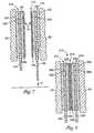
- FIG. 7 Removal of one or both of the stretch release adhesive tape structures 112 and 114 can be accomplished as illustrated in Figure 7, wherein the second stretch release adhesive tape structure 114 is illustrated in a partially debonded state.
- a progressive stretch release and removal of the object 52 from the stretch release adhesive tape structure 114 is accomplished by the application of a force F applied as illustrated in Figure 7 to the tab 136.
- Force F causes the stretching of tab 136 and progressively the stretching of the backing layer 128.
- a progressive debonding of the adhesive layers 130 and 132 occurs from the surface of the loop material 140 and the surface of the object 52, respectively.
- Figure 7 illustrates the progressive debonding at an intermediate point of the process. Continued application of force F will cause entire debonding of the second stretch release adhesive tape structure 114.
- the first stretch release adhesive tape structure 112 can be removed from the surface of object 50. That is, by application of a force to the tab 134, the stretch release adhesive tape structure 112 is removed from the surface of object 50. Thereafter, the surfaces of the objects 50 and 52 are substantially clean of adhesive and the hook and loop layers 138 and 140 could be reused.
- the tape structure 210 like tape structure 110, comprises first and second stretch release adhesive tape structures 212 and 214.
- Stretch release adhesive tape structure 212 comprises a backing layer 222, first adhesive layer 224, and second adhesive layer 226.
- the second stretch release adhesive tape structure 214 comprises backing layer 228, first adhesive layer 230 and second adhesive layer 232.
- Tabs 234 and 236 facilitate removal thereof from the respective surfaces of the objects 50 and 52.
- the first and second stretch release adhesive tape structures 212 and 214 are separably connected with one another by way of a separable connector system 216, which comprises similar intermeshing first and second connector components 238 and 240.
- the first and second connector components 238 and 240 as illustrated, each comprise a replicated (preferably micro-replicated) surface structure.
- the surface structure of the first connector component 238 is preferably similar, but need not be, to the surface structure of the second connector component 240.
- This type of separable connector system relies on the frictional characteristics of the materials and structures making up the first and second connector components 238 and 240 without macroscopic deformation and interference between the elements. Examples of this type of intermeshable connector (including similar and dissimilar mating structures) are described in U.S. Patent No. 4,875,259 to Appeldorn, U.S. Patent No. 5,360,270 to Appeldorn, and U.S. Patent No. 5,201,101 to Rouser et al.
- the ability to separate the first and second stretch release adhesive tape structures 212 and 214, and thus the objects 50 and 52, from each other is accomplished in the same way as the above-described embodiment and preferably takes into concern the same considerations. That is, the intermeshable connector system 216 should permit easy separation of the objects 50 and 52 depending on the surfaces of the objects while providing sufficient shear strength and without causing delamination of either of the stretch release adhesive tape structures 212 or 214 themselves or from the surfaces of the objects 50 and 52.
- the stretch release adhesive tape structures 212 and 214 can advantageously be reconnected to reposition the objects together in a same or different position, and if desired, the first and/or second stretch release adhesive tape structures 212 and 214 can be removed from the objects 50 and 52, respectively.
- one of the first and second stretch release adhesive tape structures can be designed to present an enlarged connector surface as compared to that of the other to permit greater flexibility of connection and positioning of the objects relative to one another. They can be moved around within the limits presented by the larger pad. The same can be accomplished by enlarging both pads; however, concern should be given to the force that may be required to separate the separable connector system 216 if both pads are maximally connected. Removal of one or both stretch release adhesive tape structures 212 and 214 is accomplished in the same way as described above and illustrated in Figure 7 wherein a progressive stretching of the backing layers 222 and 228 causes debonding of the adhesive layers from the connector system components 238 and 240 as well as the surfaces of the objects 50 and 52.
- Other mechanical connectors can also be used as the separable connector system 16 as long as the system is separable and preferably reusable.
- Other examples include without limitation snaps (plastic or metal), deformable closure systems, such as those commercially available under the trade designation "Ziplok” closures, deformable connectors having pins and sockets, and the like.
- Other closure devices using other mechanisms, such a the creation of suction by a suction cup, electrostatic charge, etc. can be utilized.
- the connector system 16 can comprise a non-tacky adhesive system including a contact responsive fastener layer, such as are disclosed and described in the published PCT application No. WO 96/24535 and the published PCT Application No. WO 94/21742.
- a contact responsive fastening layer is a non-tacky layer that has essentially no tack to paper, and allows multiple fastening and releasing cycles of the fastening layer with a target surface.
- the target surface preferably has a solubility parameter which permits the contact responsive fastening layer to have a selectable and consistently repeatable low 90° peel strength and high shear strength.
- the contact responsive fastener layer can be reused against the target surface many times without noticeable transfer or migration of either material to the other.
- An advantageous feature of the contact responsive fastener layer is that it is cleanable, for example, with isopropanol or soap and water, in order to maintain/restore its fastening characteristics.
- the contact responsive layer may be a homopolymer, a random copolymer, a block copolymer, a graft copolymer. It may be crosslinked or uncrosslinked.
- Specific examples of polymers useful as the contact responsive fastening layer include ethylene-containing copolymers, urethane polymers such as urethanes prepared by the reaction of an isocyanate and an isocyanate-reactive compound, acrylic and acrylate polymers, urethane-acrylate polymers, butyl rubber, butadiene-acrylonitrile polymers and butadiene-acrylonitrile-isoprene polymers. Blends and mixtures of polymeric materials may be used if desired.
- a preferred polymer for the contact responsive fastener layer is a butadiene-acrylonitrile-isoprene polymer as described in published PCT Application No. WO 94/21742.
- the first connector component 38 may comprise such a contact responsive fastener material.
- the second connector component 40 may comprise a material which provides a target surface to which the contact's responsive fastener material can releasably and reusably connect. Target surfaces are provided as a surface of a layer comprising the second connector component 40 in the illustrated embodiment. As shown, adhesive layers 26 and 30 bond the contact responsive fastener layer (first connector component 38) and the target surface material layer (second connector component 40) to the first and second stretch release adhesive tape structure 12 and 14.
- Target surfaces useful in the present invention may be selected from a wide variety of materials.
- Useful target surfaces are materials that do not bond permanently to the contact responsive fastening layer.
- Examples of useful target surfaces include those materials previously identified as being useful for the fastening layer, polycarbonate, polyacrylonitrile, butadiene-styrene polymers, poly(methylmethacrylate), polyamide, ethylene vinylacetate copolymer, treated and untreated poly(ethylene terephthalate), material available under the trade designation "Surlyn", polystyrene, polyolefins, such as polyethylene, including high density polyethylene, low density polyethylene, linear low density polyethylene, and linear ultra low density polyethylene, polypropylene, and polybutylenes, vinyl copolymers, and polyvinyl acetates; olefinic copolymers, such as ethylene/methacrylate copolymers, ethylene/vinyl acetate copolymers, acrylonitrile-butadiene-st
- the target surface can be provided as one of the major surfaces of one of the layers of either the first and second stretch release adhesive tape structures 12 and 14, such as a surface of the backing layer 28, for example.
- the first connector component 38 comprising the contact responsive fastener material, can be repositionably connected with the target surface of the backing layer 28. Again, separation between first and second stretch release adhesive tape structures 12 and 14 is provided. Then, the stretching of each backing layer 22 and 28 can remove the first and second stretch release adhesive tape structures 12 and 14 from the objects to which they are applied.
- an adhesive tape 610 can: comprise first and second stretch release adhesive tape structures 612 and 614, wherein each of the first and second stretch release adhesive tape structures 612 and 614 comprises a backing layer 622 and 628, respectively, and an adhesive layer 624 and 632, respectively, for bonding between objects 50 and 52.
- a single layer of contact responsive fastener material 638 is bonded between the first and second stretch release adhesive tape structures 612 and 614 to provide the connector system 616.
- the surfaces of backing layers 622 and 628 provide target surfaces to which the contact responsive fastener layer 638 is bonded.
- the surfaces may comprise the same material or different material.
- one of the bonds can be the primary releasable and reusable bond to act as the separable connector system in accordance with the present invention.
- the other bond can be releasable or permanent.
- one or both may be treated to alter its adhesion or bonding to the contact responsive fastener layer 638.
- one target surface may be treated by corona discharge. Stretch release of the first and second stretch release adhesive tape structures 612 and 614 from objects 50 and 52 would be done the same way as described above. Separation prior to stretch release is facilitated by the repositionable connection between the contact responsive fastener layer and at least one of the target surfaces.
- Yet another contemplated embodiment comprises the provision of magnetic material as the first and second connector components 38 and 40.
- Preferable magnetic materials are those flexible magnetic material strips, which are conventionally known.
- rigid magnetic material can also be used in accordance with the present invention, depending on the particular application.
- the first connector component 38 may comprise a layer of such magnetic strip material and the second connector component 40 may comprise a similar magnetic material strip which are arranged relative to one another to create an attractive force.
- one of the connector component layers 38 or 40 may comprise instead a magnetically attractive material such as a thin sheet of iron or steel or a metal vapor-coated polymeric film. In the same manner as two magnetic strips, a layer of magnetically attractive material will be attracted to one magnetic strip.
- An additional advantage of the cooperating magnetic strips or a magnetic strip with magnetically attractive material is that the objects which are connected together by such a tape construction can be relatively repositioned even without separating the first and second stretch release adhesive tape structures 12 and 14 from one another.
- the combination of magnetic strips or magnetic strip and magnetically attractive material will permit relative sliding while maintaining contact with one another. This is particularly useful for adjusting or aligning the objects to one another. This ability can be enhanced by providing a larger pad of at least the first or second connector components 38 or 40 relative to the other.
- At least one of the first and second connector components 38 and 40 may comprise a low adhesion material which permits separation and repositioning.
- the other of the first and second connector components 38 and 40 may comprise a material which is easily separable from and reconnectable to such a low adhesion material.
- both components 38 and 40 may comprise a same or different low adhesion material if they can be adequately separated from one another.
- the low adhesion material may be provided as the second adhesive layer 26, for example, without the provision of any specific connector component 38.
- One of the major surfaces of the backing layer 28 can provide the target surface for the low adhesion material instead of a surface of a second connector component 40, although the adhesive layer 30 may be included so long as it permits separation with the low adhesion material.
- One type of low adhesion material suitable for this technique is the low-tack adhesive used in making repositionable notes which are commercially available under the trade designation "Post-it” from Minnesota Mining and Manufacturing of St. Paul, Minnesota.
- one of the first and second stretch release adhesive tape structures can be designed to present an enlarged connector surface as compared to that of the other to permit greater flexibility of connection and positioning of the objects relative to one another.
- the components 38 and 40 may also be replaced with a single layer of material that permits separation from one or both adhesive layers 26 and 30.
- a single layer of material that permits separation from one or both adhesive layers 26 and 30.
- well known silicone release papers which are commonly used as adhesive tape liners, can be used in making such a single layer that could be provided between two adhesive layers.
- a film can be coated with a low adhesion backing material, as are also well-known (and have been developed to permit the adhesive of a tape to release from the tape backing when in roll form).
- One or both sides of the single layer may be treated. If only one side of such a single layer is treated to be releasable, then only one adhesive layer 26 or 30 would be separable, which functions in accordance with the present invention.
- both sides of such a single layer are releasably treated, then both sides can release, although one bond may be more aggressive than the other depending on the adhesives (which may be different), the release treatment to the single layer, or surface treatments (to either the adhesive or the single layer material).
- a magnetic surface or contact responsive fastener surface could also be structured in the manner of an intermeshing connector or may include a low adhesion material layer.
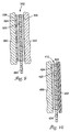
- FIG. 9 and 10 Illustrated in Figures 9 and 10 are further embodiments in accordance with the present invention where but a single connector surface is adequate for connection to a particular object surface. In these cases, only a single stretch release adhesive tape structure is thus required.
- Illustrated in Figure 9 is a stretch release adhesive tape structure 312 comprising a backing layer 322, a first adhesive layer 324 and a second adhesive layer 326.
- a tab 334 facilitates removal of the stretch release adhesive tape structure 312.
- the stretch release adhesive tape structure 312 is shown connected between a first object 350 and a second object 352.
- a single connector component 338 is connected to the stretch release adhesive tape structure 312 at its first adhesive layer 324, as illustrated.
- the second adhesive layer 326 is shown bonded to the surface of object 352.
- the surface of the connector component 338 would have a particular affinity or capability to connect with a surface of object 350.
- the connector component 338 may comprise a magnetic strip such as a flexible magnetic strip, as discussed above. This would permit the objects 350 and 352 to be separated from one another and then allow the stretch release adhesive tape strip 12 to be removed from the surface of the object 352 without having to extend the tab 334 out from between the objects 350 and 352. That is, this single stretch release structure adhesive tape version includes the same advantages as the double stretch release adhesive tape structures discussed above. Once the objects 350 and 352 are separated, access to the stretch release tab 334 is provided.
- the connector component 338 comprises a material such as a hook material (discussed above) and wherein the object 350 includes a surface that inherently provides a loop type structure, such as a loose fabric material. If the object 350 provides a surface that is suitable as a target layer for a contact responsive fastener, as discussed above, the connector component 338 may simply comprise a contact responsive fastener material. In other words, the object 350 may be a type of object which is by its own construction is provided with a surface that can act as one of the parts of a connector system, whereby it already possesses a specific capability to cooperate with the material or structure of a connector component 338.
- Figure 10 shows a structure similar to Figure 9 including a stretch release adhesive tape structure 412 connecting a first object 450 with a second object 452 in a separable and removable manner.
- the stretch release adhesive tape structure 412 comprises a backing layer 422, a first adhesive layer 424 and a second adhesive 426 that comprises a low adhesion material provided directly onto a major surface of the backing layer 422.
- a suitable low-tack adhesive suitable for this application is again the adhesive used in making repositionable notes which are commercially available under the trade designation "Post-it” from Minnesota Mining and Manufacturing Company ("3M”) of St. Paul, Minnesota.
- an object 452 comprises a light object such as a sheet of paper which is to be separable from and potentially repositionable on the surface of object 450.
- stretching the tab 434 and thus the backing 422 will cause debonding of the adhesive layer 424 from the surface of object 450.
- a separable connection is provided as well as a removable connection of the adhesive tape from an object.
- the tab 434 can remain hidden between the objects 450 and 452 because removal of the object 452 facilitates the ability to remove the stretch release adhesive tape structure 412 from the surface of object 450.
- the separable connector layer or layers may also comprise a stretchable material (elastic or plastic). Then, upon stretch removal of the tape structure, the separable connector component of that tape structure may be stretched with the backing layer thereof.
- the stretchable separate component layer can be heat laminated or otherwise connected to the backing layer instead of using adhesive.
- the backing layer or layers may be modified to optimize performance for a particular application.
- foams are preferred to add resiliency and comformability, while films improve load bearing and rupture strength.
- the combined backing must be sufficiently extensible for debonding to occur but of sufficient tensile strength so as not to rupture during debonding.
- more layers, (films/foams, etc.) can be provided in any number of ways depending on the application.
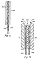
- FIG 11 illustrates a preferred construction of a backing layer suitable for use in any of the above-described backing layers.
- a foam layer 500 is illustrated laminated with a first film layer 502 and a second film layer 504.
- the external major surfaces of the film layers 502 and 504 are coated with adhesive layers 506 and 508 of similar or different adhesive composition.
- the foam layer 500 and film layers 502 and 504 can be laminated together in any number of ways including co-extrusion, heat lamination, use of adhesives or other conventional methods.
- a polyethylene/ ethylene/vinyl acetate (EVA) copolymer foam layer is heat laminated with two layers of polyethylene film.
- EVA polyethylene/ ethylene/vinyl acetate
- Suitable materials for any of the stretchable layers described in any of the embodiments above include any materials which are stretchable without rupture by at least 50 percent elongation at break and which have sufficient tensile strength so as not to rupture before debonding.
- stretchable materials may be either elastically deformable or plastically deformable provided sufficient stretching is possible to cause adhesive debonding of both adhesive surfaces for stretch removal.
- Suitable plastic backing materials are disclosed in U.S. Patent Nos. 5,516,581 and 5,672,402 to Kreckel et al and in co-pending U.S. Patent application serial number 08/308,937 (Bries et al.), each of which are commonly owned by the Assignee of the present application.
- polystyrene foam or solid polymeric film layer in the backing of the tape of this invention of the type utilizing a plastic backing include polyolefins, such as polyethylene, including high density polyethylene, low density polyethylene, linear low density polyethylene, and linear ultra low density polyethylene, polypropylene, and polybutylenes; vinyl copolymers, such as polyvinyl chlorides, both plasticized and unplasticized, and polyvinyl acetates; olefinic copolymers, such as ethylene/methacrylate copolymers, ethylene/vinyl acetate copolymers, acrylonitrile-butadiene-styrene copolymers, and ethylene/propylene copolymers; acrylic polymers and copolymers; polyurethanes; and combinations of the foregoing.
- polyolefins such as polyethylene, including high density polyethylene, low density polyethylene, linear low density polyethylene, and linear ultra low density polyethylene, polypropylene, and polybut
- plastic or plastic and elastomeric materials such as polypropylene/polyethylene, polyurethane/polyolefin, polyurethane/polycarbonate, polyurethane/polyester, can also be used.
- Polymeric foam layers for use in the plastic backing of the tapes of the invention generally will have a density of about 2 to about 30 pounds per cubic foot (about 32 to about 481 kg/m 3 ), particularly in tape constructions where the foam is to be stretched to effect debonding.
- plastic polymeric foam layers in the backing of the tapes of the invention are polyolefin foams.
- Polymeric foam layers are most preferably polyolefin foams available under the trade designations "Volextra” and “Volara” from Voltek, Division of Sekisui America Corporation, Lawrence, Massachusetts.
- Elastomeric materials suitable as backings for tapes in accordance with the present invention include styrene-butadiene copolymer, polychloroprene (neoprene), nitrile rubber, butyl rubber, polysulfide rubber, cis-i,4-polyisoprene, ethylene-propylene terpolymers (EPDM rubber), silicone rubber, polyurethane rubber, polyisobutylene, natural rubber, acrylate rubber, thermoplastic rubbers such as styrene butadiene block copolymer and styrene-isoprene-styrene block copolymer and TPO rubber materials.
- Solid polymeric film backings are preferably selected from polyethylene and polypropylene films, with the most preferred materials being unoriented linear low density and ultra low density polyethylene films.
- a preferred polyethylene film is that available under the trade designation "Maxilene 200" from Consolidated Thermoplastics Company, Schaumburg, Illinois.
- the backing may vary in overall thickness so long as it possesses sufficient integrity to be processable and provides the desired performance in respect to stretching properties for debonding the backing or tape from a surface.
- the specific overall thickness selected for a backing will depend upon the physical properties of the polymeric foam layer or layers and any solid polymeric film layer forming the backing. Where only one polymeric film or foam layer of a multi-layer backing is intended to be stretched to effect debonding, that layer should exhibit sufficient physical properties and be of a sufficient thickness to achieve that objective.
- a plastic polymeric film layer such as is contained in the construction of Figure 11, preferably will be about 0.4 to 10 mils (0.01mm to 0.25mm) in thickness, and will most preferably be about 0.4 to 6 mils (0.01mm to 0.15mm) in thickness.
- the adhesive of the adhesive layers can comprise any pressure-sensitive adhesive, with the particular adhesion properties being dependent on the use of the tape, with the preferred adhesion properties generally ranging from about 4 N/dm to about 200 N/dm, preferably from about 25 N/dm to about 100 N/dm, at a peel angle of 180°, measured according to PSTC-1 and PSTC-3 and ASTM D 903-83 at a peel rate of 12.7 cm/min. Adhesives having higher peel adhesion levels usually require backings having higher tensile strength.
- Pressure-sensitive adhesives suitable for being made into solid adhesive layers or for application to one side of a separate backing and/or the other in the tapes of the invention include tackified rubber adhesives, such as natural rubber; olefins; silicones, such as silicone polyureas; synthetic rubber adhesives such as polyisoprene, polybutadiene, and styrene-isoprene-styrene, styrene-ethylene-butylene-styrene and styrene-butadiene-styrene block copolymers, and other synthetic elastomers; and tackified or untackified acrylic adhesives such as copolymers of isooctylacrylate and acrylic acid, which can be polymerized by radiation, solution, suspension, or emulsion techniques. Preferred are synthetic rubber adhesives or acrylics.
- each adhesive layer can range from about 0.6 mils to about 40 mils (about 0.015 mm to about 1.0 mm), preferably from about 1 mils to about 16 mils (about 0.025 mm to about 0.41 mm).
- the thicker layers tend to cause the tapes to be more easily removable than do thinner layers. This is in contrast to conventional methods of removal, such as removal by peeling at peel angles of 90° or higher.
- thicker layers of adhesive tend to cause the tapes to exhibit higher peel strength at a peel angle of 180° than do thinner layers.
- the adhesive tends to be constrained by the backing and substrate for a single-coated adhesive tape and by the backing and two substrates for a double-coated adhesive tape, and is forced to undergo significant elongation.
- the adhesive layer contracts, which reduces its cross-sectional area. Since the cross-sectional area, i.e., thickness times width, of a thinner layer of adhesive is already less than that of a thicker layer of adhesive, stress, i.e., force per unit area, is greater in the thinner layer of adhesive than in the thicker layer of adhesive. This leads, in effect, to a stiffening of the adhesive. Because stiffer layers offer more resistance to deformation, the force required for debonding is greater.
- the exposed adhesive layer or layers may be laminated to a conventional release liner prior to use.
- Adhesives for adhering one polymeric foam layer to either another polymeric foam layer or a solid polymeric film layer include those pressure-sensitive adhesive compositions described above.
- the adhesive layer for adjoining one polymeric layer of the backing to another will be about 1 to 10 mils (about 0.025 to 0.25 mm) in thickness.
- Other methods of adhering the polymeric layers of the backing to one another include such conventional methods as co-extrusion or heat welding.
- the tape of this invention can be produced by any conventional method for preparing pressure-sensitive adhesive tapes.
- the adhesive can either be directly coated onto the backing, or it can be formed as a separate layer and then later laminated to the backing.
- Removing the tape from the surface of a substrate can be carried out by simply stretching the tape in a direction up to an angle of about 35° from the surface.
- the tape can be removed from the surface of a substrate by stretching the tape at an angle of no greater than about 10°. Removal at the appropriate angle will result in leaving no substantial or appreciable adhesive residue and in preventing the surface of the substrate from being damaged.
- Debonding of a highly elongated adhesive tape of this invention at low angles is characterized by a "sharp" type of crack propagation.
- a sharp crack leads to high stress concentration at the crack front, where there is a low volume of adhesive material (in which stress may be dissipated).
- High stress concentration at the crack front leads to what is called brittle cleavage failure of the adhesive. Such failure typically occurs with low force (because of the low amount of energy dissipated in the adhesive material) and is cleanly interfacial.
- the backing tends not to stretch and the adhesive tends to undergo filamentation and rupture cohesively.
- the adhesive tends to undergo filamentation and rupture cohesively.
- the observed filamentation of the adhesive at higher angles serves principally as an energy dissipation mechanism, analogous to craze fibrils found in glassy materials.
- the greater the energy dissipation the greater the resistance to peeling and the higher the force required to peel the tape.
- a larger volume of material is involved in energy dissipation, and, as stated previously, stress is less concentrated.
- the adhesive filaments rupture cohesively to leave residue of adhesive on the surface or to cause damage to the surface.
- the tape of this invention can be used in several areas, including the following categories:
- the particular construction of the tape e.g., the type of backing, the type of adhesive compositions, and relative position of backing and adhesive layers, are often required to be different for each category of use.
Landscapes
- Chemical & Material Sciences (AREA)
- Organic Chemistry (AREA)
- Adhesive Tapes (AREA)
Claims (2)
- Klebeband zum Befestigen mehrerer Gegenstände aneinander, wobei das Band eine dehnbare erste Trägerschicht mit einer ersten und einer zweiten Hauptoberfläche und einem ersten und einem zweiten Ende, eine Klebeoberfläche über mindestens einem Abschnitt der ersten Hauptoberfläche der ersten Trägerschicht zum Verbinden mit einer Oberfläche eines Gegenstandes und eine trennbare Verbindungsoberfläche, die mindestens einen Abschnitt der zweiten Hauptoberfläche der ersten Trägerschicht bedeckt, umfasst, wobei die erste Trägerschicht und die Klebeoberfläche gemeinsam dehnbar sind, um progressives Lösen der Bindung zwischen der Klebeoberfläche und einem Gegenstand zu bewirken, nachdem die Klebeoberfläche mit diesem Gegenstand verbunden wurde, durch Anwenden einer Kraft auf das erste Ende der ersten Trägerschicht in einer Erstreckungsrichtung der ersten Trägerschicht zwischen ihrem ersten und ihrem zweiten Ende, und die trennbare Verbindungsoberfläche die Fähigkeit besitzt, ohne Zerstörung der trennbaren Verbindungsoberfläche und des Klebebandes mit einer zusammenwirkenden Verbindungsoberfläche verbunden, davon getrennt und wieder damit verbunden zu werden, wobei das Klebeband weiterhin eine dehnbare zweite Trägerschicht mit einer ersten und einer zweiten Hauptoberfläche und einem ersten und einem zweiten Ende, eine Klebeoberfläche über mindestens einem Abschnitt der ersten Hauptoberfläche der zweiten Trägerschicht zum Verbinden mit einer Oberfläche eines anderen Gegenstandes und eine zusammenwirkende trennbare Verbindungsoberfläche, die mindestens einen Abschnitt der zweiten Hauptoberfläche der zweiten Trägerschicht bedeckt, umfasst, wobei die zweite Trägerschicht und ihre Klebeoberfläche gemeinsam dehnbar sind, um progressives Lösen der Bindung zwischen der Klebeoberfläche und dem anderen Gegenstand zu bewirken, nachdem ihre Klebeoberfläche mit diesem Gegenstand verbunden wurde, durch Anwenden einer Kraft auf das erste Ende der zweiten Trägerschicht in einer Erstreckungsrichtung der zweiten Trägerschicht zwischen ihrem ersten und ihrem zweiten Ende, und die zusammenwirkende trennbare Verbindungsoberfläche die Fähigkeit besitzt, ohne Zerstörung der trennbaren Verbindungsoberfläche, der zusammenwirkenden Verbindungsoberfläche und des Klebebandes mit der Verbindungsoberfläche der ersten Trägerschicht verbunden, davon getrennt und wieder damit verbunden zu werden, wobei die trennbare Verbindungsoberfläche und die zusammenwirkende trennbare Verbindungsoberfläche ausgewählt sind aus der Gruppe bestehend aus:(i) ein mechanisches ineinanderverhakendes Verbindungssystem, umfassend Elemente, die sich von einer im Allgemeinen ebenen Schicht aus einem Material wegerstrecken, um mit ähnlichen zusammenwirkenden Gliedern, die sich von einer anderen im Allgemeinen ebenen Schicht wegerstrecken, zusammenzutreffen;(ii) ein ineinandergreifendes Verbindungssystem;(iii) ein auf Kontakt ansprechendes Befestigungs-Verbindungssystem;(iv) ein magnetisches Verbindungssystem; und(v) ein Verbindungssystem mit Klebstoff von niedriger Klebrigkeit.
- Kombination aus einer Mehrzahl von Gegenständen, die durch ein Klebeband nach Anspruch 1 verbunden sind.
Applications Claiming Priority (3)
| Application Number | Priority Date | Filing Date | Title |
|---|---|---|---|
| US08/989,507 US6972141B1 (en) | 1997-12-12 | 1997-12-12 | Removable adhesive tape laminate and separable fastener |
| PCT/US1998/009382 WO1999031193A1 (en) | 1997-12-12 | 1998-05-08 | Removable adhesive tape laminate and separable fastener |
| US989507 | 2001-11-20 |
Publications (2)
| Publication Number | Publication Date |
|---|---|
| EP1037954A1 EP1037954A1 (de) | 2000-09-27 |
| EP1037954B1 true EP1037954B1 (de) | 2005-04-20 |
Family
ID=25535173
Family Applications (1)
| Application Number | Title | Priority Date | Filing Date |
|---|---|---|---|
| EP98923354A Expired - Lifetime EP1037954B1 (de) | 1997-12-12 | 1998-05-08 | Entfernbares klebebandlaminat und trennbares befestigungsmittel |
Country Status (7)
| Country | Link |
|---|---|
| US (3) | US6972141B1 (de) |
| EP (1) | EP1037954B1 (de) |
| JP (1) | JP4237406B2 (de) |
| CN (1) | CN1127548C (de) |
| AU (1) | AU7566398A (de) |
| DE (1) | DE69829877T2 (de) |
| WO (1) | WO1999031193A1 (de) |
Families Citing this family (210)
| Publication number | Priority date | Publication date | Assignee | Title |
|---|---|---|---|---|
| US6972141B1 (en) * | 1997-12-12 | 2005-12-06 | 3M Innovative Properties Company | Removable adhesive tape laminate and separable fastener |
| US6691461B1 (en) * | 1998-08-13 | 2004-02-17 | Alan J. Gitkin | Shutter mounting assembly including a support bar and width-adjusting strips |
| WO2000079073A1 (de) | 1999-06-18 | 2000-12-28 | Henkel Kommanditgesellschaft Auf Aktien | Verwendung einer folie mit verankerungselementen zur mechanischen befestigung |
| US6541089B1 (en) | 1999-08-24 | 2003-04-01 | 3M Innovative Properties Company | Stretch releasing adhesive tape with integral pull tab |
| US6641910B1 (en) | 1999-08-24 | 2003-11-04 | 3M Innovative Properties Company | Stretch releasing adhesive tape with segmented release liner |
| US6558789B1 (en) * | 1999-11-10 | 2003-05-06 | 3M Innovative Properties Company | Removable tape laminate including a flexible non-stretchable support layer |
| DE19956946B8 (de) | 1999-11-26 | 2005-01-20 | Tesa Ag | Verpackung für Klebfolien |
| US6410135B1 (en) | 2000-01-21 | 2002-06-25 | 3M Innovative Properties Company | Stretch releasing adhesive tape with differential adhesive properties |
| US6746311B1 (en) * | 2000-01-24 | 2004-06-08 | 3M Innovative Properties Company | Polishing pad with release layer |
| US6866913B2 (en) | 2000-02-07 | 2005-03-15 | Douglas Hanes | Protection system |
| US6586071B1 (en) * | 2000-02-07 | 2003-07-01 | Douglas Hanes | Protection system |
| US6835452B1 (en) | 2000-06-02 | 2004-12-28 | 3M Innovative Properties Company | Adhesive article with progressive adhesive properties and method of using same |
| GB0013965D0 (en) * | 2000-06-09 | 2000-08-02 | Anchor Magnets Ltd | Flexible magnetic strip |
| US6569521B1 (en) | 2000-07-06 | 2003-05-27 | 3M Innovative Properties Company | Stretch releasing pressure sensitive adhesive tape and articles |
| DE10040966B4 (de) * | 2000-08-22 | 2006-04-06 | Uzin Tyro Ag | Selbstklebefolie |
| ES2239681T3 (es) * | 2000-09-29 | 2005-10-01 | Velcro Industries B.V. | Envase que puede volverse a cerrar y tira de cierre. |
| DE10055942A1 (de) | 2000-11-10 | 2002-06-06 | Tesa Ag | Haftklebemasse und ihre Verwendung |
| DE10063854A1 (de) | 2000-12-21 | 2002-09-05 | Tesa Ag | Wiederablösbare Vorrichtung |
| DE10064160A1 (de) | 2000-12-22 | 2002-08-14 | Tesa Ag | Klebfolienstreifen |
| US6660352B2 (en) | 2001-01-09 | 2003-12-09 | 3M Innovative Properties Company | Adhesive electrostatic sheets |
| US20020090509A1 (en) * | 2001-01-09 | 2002-07-11 | 3M Innovative Properties Company | Electrostatic sheets with adhesive |
| WO2002086753A1 (en) * | 2001-04-17 | 2002-10-31 | Timothy Conner | Digital audio player |
| US6811126B2 (en) | 2001-09-13 | 2004-11-02 | 3M Innovative Properties Company | Stretch releasing adhesive tape article with flexible cover |
| US6641096B2 (en) | 2001-09-13 | 2003-11-04 | 3M Innovative Properties Company | Stretch releasing adhesive tape article with bundling strap |
| US20030096066A1 (en) * | 2001-11-21 | 2003-05-22 | Clark Judith C. | Reusable ornament and reusable ornament coupling apparatus and method |
| US7063887B2 (en) | 2002-02-04 | 2006-06-20 | 3M Innovative Properties Company | Stretch releasable foams, articles including same and methods for the manufacture thereof |
| DE10204930A1 (de) * | 2002-02-07 | 2003-09-04 | Tesa Ag | Verfahren zur Herstellung eines Klebestreifenlaminates |
| DE10212049A1 (de) | 2002-03-19 | 2003-10-02 | Tesa Ag | Haftklebemasse und Verfahren zur Herstellung hierzu |
| US6866928B2 (en) | 2002-04-08 | 2005-03-15 | 3M Innovative Properties Company | Cleanly removable tapes and methods for the manufacture thereof |
| US6991133B2 (en) * | 2002-08-06 | 2006-01-31 | Unilever Home & Personal Care Usa Division Of Conopco, Inc. | Wall mountable personal care products using stretch release adhesives |
| US6889458B2 (en) * | 2002-08-29 | 2005-05-10 | John S. Copley | Flexible artwork display system |
| US7028958B2 (en) | 2002-11-01 | 2006-04-18 | 3M Innovative Properties Company | Stretch releasing adhesive article with shape retaining member |
| DE10252089A1 (de) | 2002-11-08 | 2004-05-27 | Tesa Ag | Klebemasse und Verwendung derselben für einen Haftklebfolienstreifen aus mindestens einer Schicht, der sich durch dehnendes Verstrecken im wesentlichen in der Verklebungsebene rückstands- und zerstörungsfrei wieder ablösen lässt |
| DE10317788A1 (de) | 2003-04-16 | 2004-12-02 | Tesa Ag | Wiederverwendbare, rückstands- und beschädigungsfrei wiederablösbare, elastische Klebefolie |
| US6975703B2 (en) * | 2003-08-01 | 2005-12-13 | General Electric Company | Notched transmission target for a multiple focal spot X-ray source |
| JP2005146212A (ja) * | 2003-11-19 | 2005-06-09 | Three M Innovative Properties Co | 片面粘着テープ |
| DE10361540A1 (de) * | 2003-12-23 | 2005-07-28 | Tesa Ag | Chemisch vernetzbare, durch Zug in Richtung der Verklebungsebene lösbare Klebestreifen |
| EP1550546A1 (de) * | 2003-12-29 | 2005-07-06 | Mactac Europe S.A. | Verfahren zur Mikrostrukturierung einer Oberfläche eines mehrschichtigen flexiblen Substrats, und mikrostrukturiertes Substrat |
| US7599420B2 (en) * | 2004-07-30 | 2009-10-06 | Rearden, Llc | System and method for distributed input distributed output wireless communications |
| US20060211970A1 (en) * | 2005-03-16 | 2006-09-21 | Sciulli Frank J | Releasable application systems and releasable medical device systems |
| US20070020964A1 (en) * | 2005-07-22 | 2007-01-25 | Domintech Co., Ltd. | Memory module with chip hold-down fixture |
| US20070044198A1 (en) * | 2005-08-23 | 2007-03-01 | Whicker Rebecca A | Blouse front closer |
| DK176367B1 (da) * | 2005-09-19 | 2007-10-01 | Lm Glasfiber As | Materialelag til optagelse af overskydende lim |
| AU2007240851A1 (en) * | 2006-04-22 | 2007-11-01 | Jack P. Deliddo | Apparatus and method for attaching solar panels to roof system surfaces |
| US7506450B2 (en) | 2006-06-30 | 2009-03-24 | The Stanley Works | Adhesive mount for a leveling device and a leveling device |
| CN101489802B (zh) * | 2006-07-14 | 2011-01-26 | 3M创新有限公司 | 附着系统和与附着系统结合使用的分配器 |
| US20080120935A1 (en) * | 2006-07-31 | 2008-05-29 | Certainteed Corporation | Vapor retarder fastening strip |
| DE102006038719A1 (de) | 2006-08-18 | 2008-02-21 | Tesa Ag | Haftklebestreifen für feuchtigkeitsunempfindliche wiederablösbare Verklebungen |
| CN101135635B (zh) * | 2006-09-01 | 2011-01-05 | 鸿富锦精密工业(深圳)有限公司 | 测量镜头模组内滤光片附着力的方法 |
| US7931160B2 (en) * | 2006-09-06 | 2011-04-26 | 3M Innovative Properties Company | Vertically mounted shelf assembly and accessories therefor |
| CN101511233B (zh) * | 2006-09-06 | 2011-01-26 | 3M创新有限公司 | 具有矩形框架和可拆卸式托盘的壁挂式搁架系统 |
| NZ575470A (en) | 2006-09-06 | 2012-03-30 | 3M Innovative Properties Co | Horizontally mounted shelf assembly attachable to the wall using stretch releasing adhesive strip |
| CA2662783C (en) * | 2006-09-06 | 2014-11-04 | 3M Innovative Properties Company | Wall mountable wire grid organizer system with removable accessories |
| CA2662160C (en) * | 2006-09-06 | 2014-01-14 | 3M Innovative Properties Company | Adhesively mountable angled wall shelf |
| US20080135159A1 (en) | 2006-12-12 | 2008-06-12 | 3M Innovative Properties Company | Stretch releasing pressure-sensitive adhesive articles and methods of using the same |
| US20080141597A1 (en) * | 2006-12-18 | 2008-06-19 | O'rourke Barbara Klimowicz | Flashing for integrating windows with weather resistant barrier |
| US20080229561A1 (en) * | 2007-03-19 | 2008-09-25 | Robert Hondel | Crutch Fastener for Inverted Crutch |
| US8685528B2 (en) * | 2007-04-20 | 2014-04-01 | GM Global Technology Operations LLC | Shape memory polymer and adhesive combination and methods of making and using the same |
| US8628838B2 (en) | 2007-04-20 | 2014-01-14 | GM Global Technology Operations LLC | Multilayer thermo-reversible dry adhesives |
| US8618238B2 (en) | 2007-04-20 | 2013-12-31 | GM Global Technology Operations LLC | Shape memory epoxy polymers |
| US7833577B2 (en) * | 2007-05-11 | 2010-11-16 | 3M Innovative Properties Company | Methods of making a pressure-sensitive adhesive assembly |
| US8334037B2 (en) * | 2007-05-11 | 2012-12-18 | 3M Innovative Properties Company | Multi-layer assembly, multi-layer stretch releasing pressure-sensitive adhesive assembly, and methods of making and using the same |
| US8012292B2 (en) * | 2007-05-23 | 2011-09-06 | GM Global Technology Operations LLC | Multilayer adhesive for thermal reversible joining of substrates |
| US7892384B2 (en) * | 2007-06-28 | 2011-02-22 | 3M Innovative Properties Company | Removable adhesive tape and pull tab, and method of forming |
| US7824753B2 (en) * | 2007-06-28 | 2010-11-02 | 3M Innovative Properties Company | Removable adhesive tape with foldable pull tab |
| US7857130B2 (en) * | 2007-06-28 | 2010-12-28 | 3M Innovative Properties Company | Removable adhesive tape and pull tab film, and kits |
| US20100140437A1 (en) * | 2007-08-28 | 2010-06-10 | John Orban | Suction cup |
| US20090068632A1 (en) * | 2007-09-07 | 2009-03-12 | 3M Innovative Properties Company | Mountable writing assembly |
| US20090071097A1 (en) * | 2007-09-19 | 2009-03-19 | Mcdonald Raiford | Wall covering product and method of using same |
| US20090101080A1 (en) * | 2007-10-19 | 2009-04-23 | Selzer Richard M | Avian averting system and associated methods |
| US20090126118A1 (en) * | 2007-11-15 | 2009-05-21 | Teri Paszotta | Disposable cover for diaper changing station and method of use |
| US20090158525A1 (en) * | 2007-11-15 | 2009-06-25 | Teri Paszotta | Disposable cover for diaper changing station and method of use |
| GB2455962A (en) | 2007-12-24 | 2009-07-01 | Ethicon Inc | Reinforced adhesive backing sheet, for plaster |
| JP2009204155A (ja) * | 2008-01-31 | 2009-09-10 | Kanmido:Kk | 磁性を利用した固定具 |
| WO2009111655A2 (en) | 2008-03-05 | 2009-09-11 | Kcl Licensing Inc. | Dressing and method for applying reduced pressure to and collecting and storing fluid from a tissue site |
| JP5529764B2 (ja) | 2008-03-14 | 2014-06-25 | スリーエム イノベイティブ プロパティズ カンパニー | 引き伸ばし剥離可能な接着テープ |
| US8728602B2 (en) * | 2008-04-28 | 2014-05-20 | The Charles Stark Draper Laboratory, Inc. | Multi-component adhesive system |
| DE102008021740A1 (de) | 2008-04-30 | 2009-11-05 | Tesa Se | Klebemasse aus Ethylenpolymer und Verwendung derselben für einen Haftklebfolienstreifen der sich durch dehnendes Verstrecken im Wesentlichen in der Verklebungsebene rückstands- und zerstörungsfrei wieder ablösen lässt |
| WO2009134823A2 (en) * | 2008-05-01 | 2009-11-05 | 3M Innovative Properties Company | Stretchable conductive connector |
| CN102065751B (zh) * | 2008-05-01 | 2015-06-17 | 3M创新有限公司 | 生物医学传感器系统 |
| DE102008059385A1 (de) * | 2008-06-03 | 2009-12-10 | Tesa Se | Klebeband und seine Verwendung |
| US8153221B1 (en) | 2008-07-02 | 2012-04-10 | Runberg, Inc. | Adhesive device for securing clothing |
| US8826497B2 (en) * | 2008-10-14 | 2014-09-09 | Invisible Money Clip, Llc | Banknote adapted to form a magnetic money clip |
| JP5671478B2 (ja) * | 2008-12-31 | 2015-02-18 | スリーエム イノベイティブ プロパティズ カンパニー | 引き伸ばし剥離可能な感圧接着剤 |
| CN102325851B (zh) | 2008-12-31 | 2013-12-25 | 3M创新有限公司 | 可拉伸剥离的粘合带 |
| US8572907B2 (en) * | 2009-02-19 | 2013-11-05 | Saint-Gobain Performance Plastics Corporation | Attachment system of photovoltaic cell to fluoropolymer structural membrane |
| US20110123752A1 (en) * | 2009-07-10 | 2011-05-26 | Avery Dennison Corporation | Thermoplastic Shelf Talker Labels |
| US8814842B2 (en) | 2010-03-16 | 2014-08-26 | Kci Licensing, Inc. | Delivery-and-fluid-storage bridges for use with reduced-pressure systems |
| TW201203052A (en) | 2010-05-03 | 2012-01-16 | Flatfrog Lab Ab | Touch determination by tomographic reconstruction |
| AU2011274241B2 (en) * | 2010-06-30 | 2013-10-10 | Leaf Free Pty Ltd | Gutter guard mesh secured using adhesive |
| US8851440B2 (en) | 2010-09-29 | 2014-10-07 | Velcro Industries B.V. | Releasable hanging system |
| CN105999506B (zh) * | 2010-10-18 | 2019-04-12 | 费雪派克医疗保健有限公司 | 鼻插管、导管和固定系统 |
| CA2814374A1 (en) * | 2010-10-21 | 2012-06-14 | University Of Massachusetts | High capacity easy release extended use adhesive devices |
| GB2488749A (en) | 2011-01-31 | 2012-09-12 | Systagenix Wound Man Ip Co Bv | Laminated silicone coated wound dressing |
| GB201106491D0 (en) | 2011-04-15 | 2011-06-01 | Systagenix Wound Man Ip Co Bv | Patterened silicone coating |
| CA2774386A1 (en) * | 2011-04-15 | 2012-10-15 | Tac-Fast Systems Canada Limited | Methods and systems for engagement of decorative covering |
| WO2012151734A1 (en) * | 2011-05-06 | 2012-11-15 | Tpk Touch Solutions (Xiamen) Inc. | Optical bonding apparatus, touch-sensitive display using the same and method of making the same |
| WO2013011525A1 (en) * | 2011-07-18 | 2013-01-24 | Bhushan Fani | Fibrous handy cleaner for devices |
| DE102011108726A1 (de) * | 2011-07-26 | 2013-01-31 | Paul Hartmann Ag | Anschlussvorrichtung zur Verwendung bei der Unterdruckbehandlung von Wunden |
| TWI454384B (zh) * | 2011-07-28 | 2014-10-01 | Young Lighting Technology Inc | 黏合結構 |
| US8859068B2 (en) * | 2011-08-04 | 2014-10-14 | Apple Inc. | Adhesive stack with a central shear layer |
| US10945809B2 (en) * | 2011-09-01 | 2021-03-16 | Mike Zacher | Prosthodontic tool and method for placing and fitting crowns and inlays |
| US8430371B2 (en) * | 2011-09-02 | 2013-04-30 | Steven G. Boelstler | Quick release hook and loop device |
| US20130056142A1 (en) * | 2011-09-02 | 2013-03-07 | Joseph W. Fiore | Decorative decal for recessed light trim |
| US10940047B2 (en) | 2011-12-16 | 2021-03-09 | Kci Licensing, Inc. | Sealing systems and methods employing a hybrid switchable drape |
| WO2013090810A1 (en) | 2011-12-16 | 2013-06-20 | Kci Licensing, Inc. | Releasable medical drapes |
| CN104094000B (zh) | 2012-01-19 | 2016-09-28 | 马萨诸塞大学 | 双面及多面粘附装置 |
| FR2991370B1 (fr) * | 2012-06-04 | 2014-05-16 | Saint Gobain | Joint de liaison pour paroi vitree et paroi vitree |
| DE102012214178A1 (de) * | 2012-08-09 | 2014-06-12 | Paul Hartmann Ag | Anschlussvorrichtung zur Verwendung bei der Unterdrucktherapie von Wunden |
| EP2730627A1 (de) * | 2012-11-13 | 2014-05-14 | RAFI GmbH & Co. KG | Flächengebilde |
| KR20150085837A (ko) * | 2012-11-16 | 2015-07-24 | 케이씨아이 라이센싱 인코포레이티드 | 패턴 접착층을 구비한 의료용 드레이프 및 그 제조 방법 |
| GB201222770D0 (en) | 2012-12-18 | 2013-01-30 | Systagenix Wound Man Ip Co Bv | Wound dressing with adhesive margin |
| DE202013012788U1 (de) | 2012-12-19 | 2019-08-29 | Tesa Se | Wiederablösbarer Haftklebestreifen |
| DE102012223670A1 (de) | 2012-12-19 | 2014-06-26 | Tesa Se | Wiederablösbarer Haftklebestreifen |
| JP2016510390A (ja) | 2013-02-06 | 2016-04-07 | ユニバーシテイ・オブ・マサチユセツツ | 調節可能な角度を有する耐重量接着装置 |
| WO2014152485A1 (en) | 2013-03-14 | 2014-09-25 | University Of Masssachusetts | Devices for application and load bearing and method of using the same |
| JP2016518478A (ja) | 2013-03-15 | 2016-06-23 | ユニバーシテイ・オブ・マサチユセツツ | 高能力剥離容易長期使用接着閉鎖デバイス |
| DE102013206624A1 (de) | 2013-04-15 | 2014-10-16 | Tesa Se | Haftklebemasse und Verwendung derselben in einem Haftklebstreifen |
| KR20140132885A (ko) * | 2013-05-08 | 2014-11-19 | 엘지전자 주식회사 | 태양 전지 모듈 및 이에 사용되는 에지 테이프 |
| JP6171029B2 (ja) | 2013-06-03 | 2017-07-26 | スリーエム イノベイティブ プロパティズ カンパニー | 取外し可能壁装飾キット、システム、及び方法 |
| CN105338939A (zh) * | 2013-06-20 | 2016-02-17 | 3M创新有限公司 | 拉伸剥离制品和紧固件 |
| EP3578209B1 (de) | 2013-08-26 | 2023-12-20 | 3M Innovative Properties Company | Verbandschnittstelle mit feuchtigkeitsregelungsfunktion und dichtungsfunktion |
| US9554674B2 (en) | 2013-10-08 | 2017-01-31 | Liberty Hardware Mfg. Corp. | Shower rod mounting assembly |
| US10188179B2 (en) * | 2013-10-11 | 2019-01-29 | Aplix | Fastener |
| US9474338B2 (en) * | 2013-10-11 | 2016-10-25 | Aplix | Fastener |
| EP3470030A1 (de) | 2013-10-28 | 2019-04-17 | KCI Licensing, Inc. | Hybrides dichtungsband |
| EP3257486B1 (de) | 2013-10-30 | 2019-06-05 | KCI Licensing, Inc. | Kondensatabsorbierendes und -ableitendes system |
| EP3821859A1 (de) | 2013-10-30 | 2021-05-19 | 3M Innovative Properties Co. | Verband mit unterschiedlich grossen perforationen |
| EP3744361A1 (de) | 2013-10-30 | 2020-12-02 | KCI Licensing, Inc. | Absorbierende leitung und system |
| WO2015065616A1 (en) | 2013-10-30 | 2015-05-07 | Kci Licensing, Inc. | Dressing with sealing and retention intereface |
| EP3479803B1 (de) | 2014-02-28 | 2021-03-31 | 3M Innovative Properties Company | Hybridabdecktuch mit einem perforierten gelbeschichteten netz |
| US11026844B2 (en) | 2014-03-03 | 2021-06-08 | Kci Licensing, Inc. | Low profile flexible pressure transmission conduit |
| USD739661S1 (en) | 2014-03-06 | 2015-09-29 | 3M Innovative Properties Company | Decorative display |
| USD742124S1 (en) | 2014-03-06 | 2015-11-03 | 3M Innovative Properties Company | Decorative display |
| USD741069S1 (en) | 2014-03-06 | 2015-10-20 | 3M Innovative Properties Company | Decorative display base |
| WO2015138562A2 (en) * | 2014-03-11 | 2015-09-17 | Innovation Plus, Llc | System for applying an ultrasonic transducer to a fastener |
| CN103950507A (zh) * | 2014-04-09 | 2014-07-30 | 上海大学 | 一种复合型船用降噪结构 |
| DE102014208263A1 (de) | 2014-04-30 | 2015-11-05 | Tesa Se | Ablösehilfe für eine wiederablösbare Klebefolie |
| DE102014208264A1 (de) | 2014-04-30 | 2015-11-05 | Tesa Se | Hilfsklebeband für eine wiederablösbare Klebefolie |
| US10406266B2 (en) | 2014-05-02 | 2019-09-10 | Kci Licensing, Inc. | Fluid storage devices, systems, and methods |
| WO2015188003A1 (en) | 2014-06-05 | 2015-12-10 | Kci Licensing, Inc. | Dressing with fluid acquisition and distribution characteristics |
| CN105722437A (zh) | 2014-06-17 | 2016-06-29 | 3M创新有限公司 | 使用剥离释放粘合剂的制品支撑件 |
| GB201411317D0 (en) * | 2014-06-25 | 2014-08-06 | Birrell Laura | Shoe insert |
| JP6245445B2 (ja) * | 2014-07-07 | 2017-12-13 | Smc株式会社 | アクチュエータのタクト計測装置及びセンサ信号検知装置 |
| US10350852B2 (en) * | 2014-11-13 | 2019-07-16 | GM Global Technology Operations LLC | Systems for bonding surfaces using a releasable adhesive |
| WO2016100098A1 (en) | 2014-12-17 | 2016-06-23 | Kci Licensing, Inc. | Dressing with offloading capability |
| USD756135S1 (en) | 2015-03-05 | 2016-05-17 | 3M Innovative Properties Company | Display base |
| US9488214B2 (en) | 2015-03-06 | 2016-11-08 | John Orban | Armature-based suction device |
| US9730534B2 (en) * | 2015-03-06 | 2017-08-15 | Leslie Pierson | Magnetic mounting system and method |
| JP6895385B2 (ja) * | 2015-03-18 | 2021-06-30 | スリーエム イノベイティブ プロパティズ カンパニー | 取付けシステム |
| USD746600S1 (en) | 2015-03-19 | 2016-01-05 | 3M Innovative Properties Company | Display base |
| USD776942S1 (en) | 2015-03-19 | 2017-01-24 | 3M Innovative Properties Company | Display base |
| USD746602S1 (en) | 2015-03-19 | 2016-01-05 | 3M Innovative Properties Company | Display base |
| USD746601S1 (en) | 2015-03-19 | 2016-01-05 | 3M Innovative Properties Company | Display base |
| USD747888S1 (en) | 2015-03-19 | 2016-01-26 | 3M Innovative Properties Company | Display base |
| USD746599S1 (en) | 2015-03-19 | 2016-01-05 | 3M Innovative Properties Company | Display base |
| USD747110S1 (en) | 2015-03-19 | 2016-01-12 | 3M Innovative Properties Company | Display base |
| USD746603S1 (en) | 2015-03-26 | 2016-01-05 | 3M Innovative Properties Company | Display base |
| WO2016160364A1 (en) * | 2015-03-27 | 2016-10-06 | 3M Innovative Properties Company | Improved mounting device |
| KR20170131582A (ko) | 2015-03-27 | 2017-11-29 | 쓰리엠 이노베이티브 프로퍼티즈 컴파니 | 캔버스 장착 장치 |
| DE202015009730U1 (de) | 2015-04-02 | 2019-09-06 | Tesa Se | Wiederablösbarer Haftklebestreifen |
| DE202015009721U1 (de) | 2015-04-02 | 2019-08-23 | Tesa Se | Wiederablösbarer Haftklebestreifen |
| DE202015009724U1 (de) | 2015-04-02 | 2019-08-16 | Tesa Se | Wiederablösbarer Haftklebestreifen |
| DE102015206076A1 (de) | 2015-04-02 | 2016-10-06 | Tesa Se | Wiederablösbarer Haftklebestreifen |
| EP3075772B1 (de) | 2015-04-02 | 2020-08-26 | tesa SE | Wiederablösbarer haftklebestreifen |
| US11246975B2 (en) | 2015-05-08 | 2022-02-15 | Kci Licensing, Inc. | Low acuity dressing with integral pump |
| WO2017010951A1 (en) * | 2015-07-16 | 2017-01-19 | Oribel Pte. Ltd. | Article for mounting to a vertical surface |
| WO2017040045A1 (en) | 2015-09-01 | 2017-03-09 | Kci Licensing, Inc. | Dressing with increased apposition force |
| US10973694B2 (en) | 2015-09-17 | 2021-04-13 | Kci Licensing, Inc. | Hybrid silicone and acrylic adhesive cover for use with wound treatment |
| DE102015220072A1 (de) | 2015-10-15 | 2017-04-20 | Tesa Se | Selbstklebeartikel und dessen Verwendung zur Verklebung auf gestrichener Raufasertapete |
| DE102015220065A1 (de) | 2015-10-15 | 2017-04-20 | Tesa Se | Klebemasse, insbesondere für stripbare Klebestreifen, und Verwendung zur Verklebung auf gestrichener Raufasertapete |
| US9611407B1 (en) * | 2015-11-17 | 2017-04-04 | Sonoco Development, Inc. | Repositionable merchandising strip |
| CN105524570B (zh) * | 2016-01-18 | 2018-10-12 | 3M创新有限公司 | 胶带组件、粘结制品 |
| US20190048233A1 (en) | 2016-02-01 | 2019-02-14 | 3M Innovative Properties Company | Conformable, peelable adhesive articles |
| CN108603087A (zh) | 2016-02-01 | 2018-09-28 | 3M创新有限公司 | 改善的压敏粘合剂组合物 |
| TWI722105B (zh) | 2016-02-01 | 2021-03-21 | 美商3M新設資產公司 | 可適形、拉伸可離型黏著物品 |
| DE102016205166A1 (de) | 2016-03-30 | 2017-10-05 | Tesa Se | Darreichungsform für doppelseitig wirksame Klebemittel |
| US20180064215A1 (en) * | 2016-09-08 | 2018-03-08 | Wolf Tooth Components, LLC | Attachment system and method, and article incorporating same |
| DE102016223852A1 (de) | 2016-11-30 | 2018-05-30 | Tesa Se | Wiederablösbarer Haftklebestreifen |
| US10421414B2 (en) * | 2016-12-01 | 2019-09-24 | Lear Corporation | Contour connect |
| WO2018106421A1 (en) * | 2016-12-05 | 2018-06-14 | Walter Jackson | Head support system |
| DE102017203092A1 (de) | 2017-02-24 | 2018-08-30 | Tesa Se | Wiederablösbarer Haftklebestreifen |
| EP3600888A4 (de) | 2017-03-28 | 2021-01-13 | 3M Innovative Properties Company | Anpassbare klebeartikel |
| US10221883B2 (en) | 2017-04-07 | 2019-03-05 | Artskills, Inc. | Apparatus for supporting articles |
| DE102017206083A1 (de) | 2017-04-10 | 2018-10-11 | Tesa Se | Verklebung in elektrochemischen Zellen und Stapeln von elektrochemischen Zellen |
| US20180325256A1 (en) * | 2017-05-11 | 2018-11-15 | David R. Hall | Tabletop Attached by Removable Adhesives |
| EP3624638A4 (de) | 2017-05-15 | 2021-02-24 | Jodi A. Carroll | System zum halten von geschirr auf einem tisch |
| US11622642B2 (en) | 2017-05-15 | 2023-04-11 | Stay Put Coasters, Llc | System for holding tableware on a table |
| WO2019005831A1 (en) | 2017-06-28 | 2019-01-03 | 3M Innovative Properties Company | ADHESIVE MOUNTING DEVICES HAVING PATTERNED ADHESIVE AREAS |
| EP3672795A4 (de) | 2017-08-25 | 2021-05-12 | 3M Innovative Properties Company | Klebstoffartikel mit beschädigungsfreier entfernung |
| JP7237063B2 (ja) | 2017-08-25 | 2023-03-10 | スリーエム イノベイティブ プロパティズ カンパニー | 損傷のない取り外しを可能にする接着性物品 |
| US9909035B1 (en) * | 2017-09-29 | 2018-03-06 | Mayapple Baby Llc | Mountable articles, dual-adhesive-adhesive tape and mounting methods using them |
| DE102017220998A1 (de) | 2017-11-23 | 2019-05-23 | Tesa Se | Wiederablösbarer Haftklebestreifen |
| TW201934327A (zh) * | 2018-02-05 | 2019-09-01 | 美商3M新設資產公司 | 多層可恢復的保護性傢俱墊 |
| DE102018104750A1 (de) * | 2018-03-01 | 2019-09-05 | "Durable" Hunke & Jochheim Gmbh & Co. Kommanditgesellschaft | Informationsträgerhaltevorrichtung |
| WO2019173166A1 (en) * | 2018-03-05 | 2019-09-12 | Armstrong World Industries, Inc. | Surface covering system and method and apparatus for covering a surface |
| US11725389B2 (en) * | 2018-04-03 | 2023-08-15 | Heath Austin Hicks | Roofing debris collection apparatus |
| TW202332398A (zh) * | 2018-05-23 | 2023-08-16 | 美商3M新設資產公司 | 用以增強物體安裝體驗之黏著劑背襯定位輔助物及錨固總成 |
| CN113163963A (zh) | 2018-12-19 | 2021-07-23 | 3M创新有限公司 | 具有增强的剥离可移除性的柔性耐用件 |
| DE102019204344A1 (de) | 2019-03-28 | 2020-10-01 | Tesa Se | Wiederablösbarer Haftklebestreifen |
| JP6914543B2 (ja) * | 2019-04-05 | 2021-08-04 | 東京スレート株式会社 | 接着部材及びそれを使用した物品支持システム |
| CN110527438A (zh) * | 2019-08-02 | 2019-12-03 | 中航复合材料有限责任公司 | 一种提高复合材料胶接性能的表面处理方法 |
| KR20220085051A (ko) * | 2019-10-31 | 2022-06-21 | 킴벌리-클라크 월드와이드, 인크. | 탑재 시스템을 포함하는 흡수성 시트의 적층체 |
| US11641957B2 (en) | 2020-01-04 | 2023-05-09 | Tracer Imaging Llc | Magnetic framing system |
| EP4104042A1 (de) | 2020-02-10 | 2022-12-21 | FlatFrog Laboratories AB | Verbesserte berührungsempfindliche vorrichtung |
| WO2021212071A1 (en) * | 2020-04-16 | 2021-10-21 | Pierpont Paul | Furniture anchors and protectors |
| EP4340892A1 (de) * | 2021-05-19 | 2024-03-27 | Jeffery L. Jackson | Verfahren und vorrichtung für zerstörungsfreie klebevorrichtungen |
| US11529010B1 (en) * | 2021-12-30 | 2022-12-20 | Avertech, Inc. | Convertible metal backings and related methods |
| USD996195S1 (en) | 2022-02-28 | 2023-08-22 | 3M Innovative Properties Company | Mounting hook |
| WO2023225392A1 (en) * | 2022-05-20 | 2023-11-23 | Tracer Imaging Llc | Framing system and wall pad therefore |
Family Cites Families (23)
| Publication number | Priority date | Publication date | Assignee | Title |
|---|---|---|---|---|
| US4003538A (en) | 1975-09-02 | 1977-01-18 | Frye Bruce J | Article holding device |
| US4310137A (en) | 1980-09-08 | 1982-01-12 | Frye Bruce J | Self holding separable mount |
| US4875259A (en) | 1986-09-08 | 1989-10-24 | Minnesota Mining And Manufacturing Company | Intermeshable article |
| US4894060A (en) | 1988-01-11 | 1990-01-16 | Minnesota Mining And Manufacturing Company | Disposable diaper with improved hook fastener portion |
| US5256231A (en) | 1988-05-13 | 1993-10-26 | Minnesota Mining And Manufacturing Company | Method for making a sheet of loop material |
| US5077870A (en) | 1990-09-21 | 1992-01-07 | Minnesota Mining And Manufacturing Company | Mushroom-type hook strip for a mechanical fastener |
| US5103546A (en) | 1990-11-09 | 1992-04-14 | Minnesota Mining And Manufacturing Company | Process for preparing a strip of flexible closure material to be applied to a receptacle |
| US5516581A (en) | 1990-12-20 | 1996-05-14 | Minnesota Mining And Manufacturing Company | Removable adhesive tape |
| US5360270A (en) | 1992-04-28 | 1994-11-01 | Minnesota Mining And Manufacturing Company | Reusable security enclosure |
| US5201101A (en) | 1992-04-28 | 1993-04-13 | Minnesota Mining And Manufacturing Company | Method of attaching articles and a pair of articles fastened by the method |
| US5344177A (en) | 1992-04-28 | 1994-09-06 | Minnesota Mining And Manufacturing Company | Ski base and running surface |
| DE4233872C2 (de) | 1992-09-30 | 1994-07-28 | Beiersdorf Ag | Wiederablösbarer, selbstklebender Haken |
| KR100256884B1 (ko) | 1993-04-16 | 2000-05-15 | 스프레이그 로버트 월터 | 루프 파스너 재료보관/분배 조립체 |
| DE9306721U1 (de) | 1993-05-04 | 1993-08-05 | Weise, Heinz, 41238 Moenchengladbach, De | |
| JPH0782388A (ja) | 1993-09-01 | 1995-03-28 | Minnesota Mining & Mfg Co <3M> | 自己接着性フィルム及びそれを用いた積層体 |
| DE4339604C2 (de) | 1993-11-20 | 1996-06-05 | Beiersdorf Ag | Verwendung eines Klebfolien-Abschnitts für eine wiederablösbare Verklebung |
| US5507464A (en) | 1994-03-22 | 1996-04-16 | Minnesota Mining And Manufacturing Company | Article support using stretch releasing adhesives |
| US5733652A (en) | 1995-02-10 | 1998-03-31 | Minnesota Mining And Manufacturing Company | Banding system, banding tape and methods of using the same |
| US5672404A (en) | 1995-09-07 | 1997-09-30 | Minnesota Mining And Manufacturing Company | Attachment strips |
| DE19542212A1 (de) | 1995-11-13 | 1997-05-15 | Lohmann Gmbh & Co Kg | Lösbare Klebeverbindung |
| US6004642A (en) * | 1996-11-08 | 1999-12-21 | 3M Innovative Properties Company | Internally separable tape laminate |
| EP0885571B1 (de) | 1997-06-21 | 2003-08-27 | Tesa AG | Klebfolienstreifen-Verbund und seine Verwendung |
| US6972141B1 (en) * | 1997-12-12 | 2005-12-06 | 3M Innovative Properties Company | Removable adhesive tape laminate and separable fastener |
-
1997
- 1997-12-12 US US08/989,507 patent/US6972141B1/en not_active Expired - Lifetime
-
1998
- 1998-05-08 DE DE69829877T patent/DE69829877T2/de not_active Expired - Lifetime
- 1998-05-08 CN CN98812101A patent/CN1127548C/zh not_active Expired - Lifetime
- 1998-05-08 EP EP98923354A patent/EP1037954B1/de not_active Expired - Lifetime
- 1998-05-08 JP JP2000539101A patent/JP4237406B2/ja not_active Expired - Lifetime
- 1998-05-08 AU AU75663/98A patent/AU7566398A/en not_active Abandoned
- 1998-05-08 WO PCT/US1998/009382 patent/WO1999031193A1/en active IP Right Grant
-
2001
- 2001-05-07 US US09/764,483 patent/US6572945B2/en not_active Expired - Lifetime
-
2003
- 2003-03-24 US US10/393,982 patent/US6692807B2/en not_active Expired - Lifetime
Also Published As
| Publication number | Publication date |
|---|---|
| DE69829877D1 (de) | 2005-05-25 |
| US6972141B1 (en) | 2005-12-06 |
| CN1127548C (zh) | 2003-11-12 |
| US20020009568A1 (en) | 2002-01-24 |
| EP1037954A1 (de) | 2000-09-27 |
| DE69829877T2 (de) | 2006-01-26 |
| US6572945B2 (en) | 2003-06-03 |
| CN1281493A (zh) | 2001-01-24 |
| WO1999031193A1 (en) | 1999-06-24 |
| JP2002508432A (ja) | 2002-03-19 |
| AU7566398A (en) | 1999-07-05 |
| US20030161984A1 (en) | 2003-08-28 |
| JP4237406B2 (ja) | 2009-03-11 |
| US6692807B2 (en) | 2004-02-17 |
Similar Documents
| Publication | Publication Date | Title |
|---|---|---|
| EP1037954B1 (de) | Entfernbares klebebandlaminat und trennbares befestigungsmittel | |
| EP0843709B1 (de) | Auftragbares klebeband mit kontrollierter sequentieller entfernung | |
| EP1392787B1 (de) | Klebeartikel mit verbesserten klebeeigenschaften und methode zu dessen anwendung | |
| US6001471A (en) | Removable adhesive tape with controlled sequential release | |
| US6641892B2 (en) | Use of a piece of adhesive film for a bond which can be separated without damage and without leaving a residue | |
| EP0716672B1 (de) | Entfernbares schaumstoff-klebeband | |
| EP0563272B1 (de) | Entfernbares klebeband | |
| CA2339225C (en) | Stretch release adhesive article with secondary release member | |
| US5516581A (en) | Removable adhesive tape | |
| CN109690094B (zh) | 粘合剂安装装置 | |
| US6616790B2 (en) | Redetachable, self-adhesive device | |
| TWI821485B (zh) | 用於將物體安裝到一表面的黏著劑物品及黏著地附接其至一黏附體之一表面的方法 | |
| CA2537418A1 (en) | Releasable adhesive tape | |
| US20220098451A1 (en) | Stretch release adhesive article with hexagonal mesh | |
| WO2023163717A1 (en) | Flexible adhesive mounting articles including intermittently connected body segments | |
| TW202031837A (zh) | 包括斷續連接之本體區段的可撓性黏著劑安裝物品 | |
| MXPA98001047A (en) | Removable adhesive tape with sequential control control |
Legal Events
| Date | Code | Title | Description |
|---|---|---|---|
| PUAI | Public reference made under article 153(3) epc to a published international application that has entered the european phase |
Free format text: ORIGINAL CODE: 0009012 |
|
| 17P | Request for examination filed |
Effective date: 20000712 |
|
| AK | Designated contracting states |
Kind code of ref document: A1 Designated state(s): DE FR GB IT |
|
| 17Q | First examination report despatched |
Effective date: 20010708 |
|
| GRAP | Despatch of communication of intention to grant a patent |
Free format text: ORIGINAL CODE: EPIDOSNIGR1 |
|
| GRAS | Grant fee paid |
Free format text: ORIGINAL CODE: EPIDOSNIGR3 |
|
| GRAA | (expected) grant |
Free format text: ORIGINAL CODE: 0009210 |
|
| AK | Designated contracting states |
Kind code of ref document: B1 Designated state(s): DE FR GB IT |
|
| REG | Reference to a national code |
Ref country code: GB Ref legal event code: FG4D |
|
| REF | Corresponds to: |
Ref document number: 69829877 Country of ref document: DE Date of ref document: 20050525 Kind code of ref document: P |
|
| PLBE | No opposition filed within time limit |
Free format text: ORIGINAL CODE: 0009261 |
|
| STAA | Information on the status of an ep patent application or granted ep patent |
Free format text: STATUS: NO OPPOSITION FILED WITHIN TIME LIMIT |
|
| ET | Fr: translation filed | ||
| 26N | No opposition filed |
Effective date: 20060123 |
|
| PGFP | Annual fee paid to national office [announced via postgrant information from national office to epo] |
Ref country code: IT Payment date: 20080528 Year of fee payment: 11 |
|
| PG25 | Lapsed in a contracting state [announced via postgrant information from national office to epo] |
Ref country code: IT Free format text: LAPSE BECAUSE OF NON-PAYMENT OF DUE FEES Effective date: 20090508 |
|
| REG | Reference to a national code |
Ref country code: FR Ref legal event code: PLFP Year of fee payment: 19 |
|
| REG | Reference to a national code |
Ref country code: FR Ref legal event code: PLFP Year of fee payment: 20 |
|
| PGFP | Annual fee paid to national office [announced via postgrant information from national office to epo] |
Ref country code: DE Payment date: 20170502 Year of fee payment: 20 Ref country code: GB Payment date: 20170503 Year of fee payment: 20 Ref country code: FR Payment date: 20170413 Year of fee payment: 20 |
|
| REG | Reference to a national code |
Ref country code: DE Ref legal event code: R079 Ref document number: 69829877 Country of ref document: DE Free format text: PREVIOUS MAIN CLASS: C09J0007020000 Ipc: C09J0007200000 |
|
| REG | Reference to a national code |
Ref country code: DE Ref legal event code: R071 Ref document number: 69829877 Country of ref document: DE |
|
| REG | Reference to a national code |
Ref country code: GB Ref legal event code: PE20 Expiry date: 20180507 |
|
| PG25 | Lapsed in a contracting state [announced via postgrant information from national office to epo] |
Ref country code: GB Free format text: LAPSE BECAUSE OF EXPIRATION OF PROTECTION Effective date: 20180507 |