EP1036703A2 - Scheinwerfer - Google Patents
Scheinwerfer Download PDFInfo
- Publication number
- EP1036703A2 EP1036703A2 EP00104442A EP00104442A EP1036703A2 EP 1036703 A2 EP1036703 A2 EP 1036703A2 EP 00104442 A EP00104442 A EP 00104442A EP 00104442 A EP00104442 A EP 00104442A EP 1036703 A2 EP1036703 A2 EP 1036703A2
- Authority
- EP
- European Patent Office
- Prior art keywords
- headlight
- housing
- adjustment device
- headlights
- module
- Prior art date
- Legal status (The legal status is an assumption and is not a legal conclusion. Google has not performed a legal analysis and makes no representation as to the accuracy of the status listed.)
- Withdrawn
Links
- 239000003990 capacitor Substances 0.000 claims description 4
- 238000004146 energy storage Methods 0.000 claims description 3
- 230000004913 activation Effects 0.000 claims 1
- 238000005286 illumination Methods 0.000 description 4
- 238000010586 diagram Methods 0.000 description 2
- 230000006870 function Effects 0.000 description 2
- 239000011521 glass Substances 0.000 description 2
- 238000004519 manufacturing process Methods 0.000 description 2
- 239000007858 starting material Substances 0.000 description 2
- 230000000694 effects Effects 0.000 description 1
- 230000002996 emotional effect Effects 0.000 description 1
- 238000009434 installation Methods 0.000 description 1
Images
Classifications
-
- B—PERFORMING OPERATIONS; TRANSPORTING
- B60—VEHICLES IN GENERAL
- B60Q—ARRANGEMENT OF SIGNALLING OR LIGHTING DEVICES, THE MOUNTING OR SUPPORTING THEREOF OR CIRCUITS THEREFOR, FOR VEHICLES IN GENERAL
- B60Q1/00—Arrangement of optical signalling or lighting devices, the mounting or supporting thereof or circuits therefor
- B60Q1/02—Arrangement of optical signalling or lighting devices, the mounting or supporting thereof or circuits therefor the devices being primarily intended to illuminate the way ahead or to illuminate other areas of way or environments
- B60Q1/04—Arrangement of optical signalling or lighting devices, the mounting or supporting thereof or circuits therefor the devices being primarily intended to illuminate the way ahead or to illuminate other areas of way or environments the devices being headlights
- B60Q1/06—Arrangement of optical signalling or lighting devices, the mounting or supporting thereof or circuits therefor the devices being primarily intended to illuminate the way ahead or to illuminate other areas of way or environments the devices being headlights adjustable, e.g. remotely-controlled from inside vehicle
- B60Q1/08—Arrangement of optical signalling or lighting devices, the mounting or supporting thereof or circuits therefor the devices being primarily intended to illuminate the way ahead or to illuminate other areas of way or environments the devices being headlights adjustable, e.g. remotely-controlled from inside vehicle automatically
- B60Q1/10—Arrangement of optical signalling or lighting devices, the mounting or supporting thereof or circuits therefor the devices being primarily intended to illuminate the way ahead or to illuminate other areas of way or environments the devices being headlights adjustable, e.g. remotely-controlled from inside vehicle automatically due to vehicle inclination, e.g. due to load distribution
- B60Q1/115—Arrangement of optical signalling or lighting devices, the mounting or supporting thereof or circuits therefor the devices being primarily intended to illuminate the way ahead or to illuminate other areas of way or environments the devices being headlights adjustable, e.g. remotely-controlled from inside vehicle automatically due to vehicle inclination, e.g. due to load distribution by electric means
-
- B—PERFORMING OPERATIONS; TRANSPORTING
- B60—VEHICLES IN GENERAL
- B60Q—ARRANGEMENT OF SIGNALLING OR LIGHTING DEVICES, THE MOUNTING OR SUPPORTING THEREOF OR CIRCUITS THEREFOR, FOR VEHICLES IN GENERAL
- B60Q2200/00—Special features or arrangements of vehicle headlamps
- B60Q2200/30—Special arrangements for adjusting headlamps, e.g. means for transmitting the movements for adjusting the lamps
- B60Q2200/38—Automatic calibration of motor-driven means for adjusting headlamps, i.e. when switching on the headlamps, not during mounting at factories
Definitions
- the invention relates to a headlamp, in particular for motor vehicles, according to the Preamble of claim 1.
- Usual headlights include a cover frame that is fixed to one in the front Area arranged glass pane is connected, which together form a housing. in the The rear area of the housing has an opening into which the actual one is then placed Headlight module can be inserted and attached. Because of the inevitable Manufacturing tolerances each headlight module must be adjusted to its housing in order to achieve a prescribed optimal illumination. This is it known, the headlight module by means of mechanical adjusting screws in relation to Moving housing. This usually happens once during the manufacturing process. Due to this necessary adjustment, the headlight module is no longer arranged symmetrically to the housing, which leads to a disturbance of the aesthetic Overall impression leads. In addition, the respective Headlight modules the new headlight module can be readjusted what is very tedious due to the difficult to access set screws.
- DE 39 30 589 describes an adjustment device for the orientation of the headlights a motor vehicle known, comprising an electric control motor for the Change of position by changing the orientation of the headlights, one electrical sensor for the actual position of the headlights, including one Voltage source to which a first component with variable impedance is connected for generating a first signal that can be changed as a function of the actual position the headlights, means for specifying the target position of the headlights, including a voltage source to which an impedance variable in size is connected to generate a second depending on the target position of the Variable signal headlights and a comparison and control circuit, connected to the sensor and to the control means and designed to effect the Actuation of the engine when the actual position of the headlights from the target position deviates, the device further comprising a third component of variable impedance includes for manual actuation to determine a change in the signal that delivered with the function of the first or second component with variable impedance is used to calibrate the original setting of the Make headlights especially when installing them in
- a headlight for a motor vehicle is known from WO 97/13118, which adjusts itself using infrared transmitters and receivers. Disadvantage of all of these known headlights is that the overall aesthetic impression due to Asymmetry between headlight module and housing is disturbed.
- the invention is therefore based on the technical problem of a headlight create an improved aesthetic with optimal illumination Overall impression.
- the headlight module assigned two target positions, namely a target operating position when the Headlamp illuminates and a target stand position when the vehicle is parked or the headlight is off.
- the headlight module is used for this a change in the operating state of the motor vehicle or headlight automatically adjusted by the electrical adjustment device, namely in one preferably symmetrical position to the housing as the target stand position and in a Set operating position adjusted from the lighting point of view when switched on Headlights.
- the target operating position is determined when installing for the first time stored together with the target position in a memory module.
- the operating mode is switched on the ignition or when the headlights are switched on.
- the electrical adjustment device is an electrical Energy storage, preferably in the form of a capacitor, assigned.
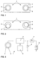
- Fig. 1 is a schematic front view of two front headlights 1 one Motor vehicle shown, each headlight 1, a housing 2 and Headlight module 3 includes.
- the housing 2 includes a not shown Cover frame and a glass or plastic pane and is with the body 4 or another part of the vehicle.
- the headlight module 3 includes essential a reflector, the actual lamp and electrical connections and Leads for the lamp.
- the headlight modules 3 are symmetrical to the housing 2 arranged so that there is a closed aesthetic overall impression for the Observer reveals, especially if the motor vehicle is parked unlit.
- FIG 2 shows an example of how the headlight modules 3 in relation to Housing 2 must be adjusted to ensure uniform illumination by the to reach both headlights 1.
- the headlight 1 comprises an electrical adjustment device 5 with assigned memory module 6.
- the electrical adjustment device 5 is above a Ignition starter switch 7 connected to a vehicle battery 8, to which a parallel Capacitor 9 is arranged.
- the first step is First installation of the headlight module 3 with regard to optimized illumination adjusted. This can also be done manually or as already from the prior art known, done automatically by means of suitable sensors. This determines the target operating position 2 is then stored in the memory module 6. For this, a Adjustment mode can be provided so that adjustment and storage automatically respectively. If the headlight is formed by means of a self-adjusting sensor system, then can optionally be dispensed with the memory module 6, so that in each case current adjust the headlights when starting up. Now the Ignition switch 7 closed, it can usually be set in motion soon of the motor vehicle are closed. On the Ignition switch is then the electrical adjustment 5 with electrical Energy supplied.
- the electrical adjustment device 5 then calls from the memory module 6 from the stored target operating position and adjusts accordingly Headlight module 3. Then the motor vehicle is parked and the Ignition starter switch 7 opened, this is done by the electrical adjustment device detected and the headlight module 3 again in the desired position according to FIG. 1 emotional.
- the electrical energy required for this is obtained from electrical energy Adjustment device 5 from the capacitor 9, which during the operating phase Battery 9 or the alternator of the motor vehicle was charged.
Landscapes
- Engineering & Computer Science (AREA)
- Mechanical Engineering (AREA)
- Lighting Device Outwards From Vehicle And Optical Signal (AREA)
Abstract
Description
- Fig. 1
- eine schematische Vorderansicht der vorderen Scheinwerfer eines Kraftfahrzeuges in einer Soll-Stand-Position,
- Fig. 2
- eine schematische Vorderansicht der vorderen Scheinwerfer in einer Soll-Betriebs-Position und
- Fig. 3
- ein schematisches Blockschaltbild zur automatischen Einstellung der Scheinwerfermodule.
Claims (6)
- Scheinwerfer, insbesondere für Kraftfahrzeuge, umfassend mindestens ein Scheinwerfermodul, ein Gehäuse und eine elektrische Verstelleinrichtung,
dadurch gekennzeichnet, daß
der elektrischen Verstelleinrichtung (5) eine Soll-Betriebs- und eine Soll-Stand-Position des Scheinwerfermoduls (3) zum Gehäuse (2) zugeordnet sind, die automatisch bei Einleitung des Betriebs- oder Standmodus' durch die elektrische Verstelleinrichtung (5) einstellbar sind. - Scheinwerfer nach Anspruch 1, dadurch gekennzeichnet, daß in der Soll-Stand-Position das Scheinwerfermodul (3) zum Gehäuse (2) zentriert angeordnet ist.
- Scheinwerfer nach Anspruch 1 oder 2, dadurch gekennzeichnet, daß die Soll-Betriebs- und/oder Soll-Stand-Position in einem Speicher-Modul (6) abgelegt sind.
- Scheinwerfer nach einem der vorangegangenen Ansprüche, dadurch gekennzeichnet, daß der Betriebsmodus mit der Aktivierung der Zündung oder der Beleuchtung gekoppelt ist.
- Scheinwerfer nach einem, der vorangegangenen Ansprüche, dadurch gekennzeichnet, daß der elektrischen Verstelleinrichtung (5) ein elektrischer Energiespeicher zugeordnet ist, mittels dessen über die elektrische Verstelleinrichtung (5) beim Wechsel vom Betriebs- zum Standmodus das Scheinwerfermodul (3) in die Soll-Stand-Position bewegbar ist.
- Scheinwerfer nach Anspruch 5, dadurch gekennzeichnet, daß der elektrische Energiespeicher als Kondensator (9) ausgebildet ist.
Applications Claiming Priority (2)
| Application Number | Priority Date | Filing Date | Title |
|---|---|---|---|
| DE19911651 | 1999-03-16 | ||
| DE1999111651 DE19911651B4 (de) | 1999-03-16 | 1999-03-16 | Scheinwerfer |
Publications (2)
| Publication Number | Publication Date |
|---|---|
| EP1036703A2 true EP1036703A2 (de) | 2000-09-20 |
| EP1036703A3 EP1036703A3 (de) | 2001-10-31 |
Family
ID=7901144
Family Applications (1)
| Application Number | Title | Priority Date | Filing Date |
|---|---|---|---|
| EP00104442A Withdrawn EP1036703A3 (de) | 1999-03-16 | 2000-03-06 | Scheinwerfer |
Country Status (2)
| Country | Link |
|---|---|
| EP (1) | EP1036703A3 (de) |
| DE (1) | DE19911651B4 (de) |
Families Citing this family (1)
| Publication number | Priority date | Publication date | Assignee | Title |
|---|---|---|---|---|
| DE102004022813B4 (de) * | 2004-05-08 | 2019-04-25 | HELLA GmbH & Co. KGaA | Kraftfahrzeugscheinwerfer |
Citations (2)
| Publication number | Priority date | Publication date | Assignee | Title |
|---|---|---|---|---|
| DE3930589A1 (de) | 1988-09-15 | 1990-03-29 | Siem Srl | Einrichtung fuer die einstellung der orientierung der scheinwerfer eines kraftfahrzeugs |
| WO1997013118A1 (en) | 1995-10-04 | 1997-04-10 | Egs, Inc. | System for self-aligning vehicle headlamps |
Family Cites Families (4)
| Publication number | Priority date | Publication date | Assignee | Title |
|---|---|---|---|---|
| DE9107346U1 (de) * | 1991-06-14 | 1992-10-08 | Robert Bosch Gmbh, 7000 Stuttgart | Vorrichtung zum Verstellen der Neigung von Scheinwerfern bei Kraftfahrzeugen |
| DE4139906A1 (de) * | 1991-12-04 | 1993-06-09 | Robert Bosch Gmbh, 7000 Stuttgart, De | Einrichtung zum verstellen der neigung von scheinwerfern bei kraftfahrzeugen |
| FR2721871B1 (fr) * | 1994-06-30 | 1996-09-20 | Valeo Vision | Projecteur a correcteur d'assiette, notamment pour vehicule automobile, piece intermediaire de montage et sous-ensemble pour un tel projecteur |
| JP3128609B2 (ja) * | 1996-02-01 | 2001-01-29 | 株式会社小糸製作所 | 車輌用灯具の照射方向制御装置 |
-
1999
- 1999-03-16 DE DE1999111651 patent/DE19911651B4/de not_active Expired - Lifetime
-
2000
- 2000-03-06 EP EP00104442A patent/EP1036703A3/de not_active Withdrawn
Patent Citations (2)
| Publication number | Priority date | Publication date | Assignee | Title |
|---|---|---|---|---|
| DE3930589A1 (de) | 1988-09-15 | 1990-03-29 | Siem Srl | Einrichtung fuer die einstellung der orientierung der scheinwerfer eines kraftfahrzeugs |
| WO1997013118A1 (en) | 1995-10-04 | 1997-04-10 | Egs, Inc. | System for self-aligning vehicle headlamps |
Also Published As
| Publication number | Publication date |
|---|---|
| EP1036703A3 (de) | 2001-10-31 |
| DE19911651A1 (de) | 2000-09-21 |
| DE19911651B4 (de) | 2007-06-14 |
Similar Documents
| Publication | Publication Date | Title |
|---|---|---|
| DE69128588T2 (de) | Programmierbare Warnleuchteneinrichtung und Verfahren | |
| DE19653431C2 (de) | Dachinnenverkleidung für ein Kraftfahrzeug | |
| DE29805142U1 (de) | Halterung für einen Innenrückspiegel eines Kraftfahrzeuges | |
| DE19923187A1 (de) | Beleuchtungssystem für ein Kraftfahrzeug | |
| DE10065541C2 (de) | Kraftfahrzeug-Leuchteneinheit und Verfahren zum Herstellen derselben | |
| DE102016206275A1 (de) | Verfahren zum Betreiben wenigstens einer Beleuchtungsvorrichtung eines stillstehenden Kraftfahrzeugs | |
| EP1163128B1 (de) | Einrichtung zur automatischen schaltung von beleuchtungseinrichtungen bei fahrzeugen | |
| DE10338756B4 (de) | Scheinwerfersystem eines Kraftfahrzeuges | |
| DE102016001578A1 (de) | Interieurbauteil für einen Innenraum eines Fahrzeugs | |
| DE3714421C2 (de) | Schaltungsanordnung für Anzeigeleuchten in Kraftfahrzeugen | |
| DE4408959C1 (de) | Schaltung für eine Anlage mit einem intermittierend betreibbaren Element, insbesondere eine Kraftfahrzeug-Warnblinkanlage | |
| DE19953994B4 (de) | Verfahren und Schaltungsanordnung zur Betätigung einer Fahrzeugbeleuchtung | |
| DE19911651B4 (de) | Scheinwerfer | |
| EP0170114A2 (de) | Aussenrückspiegel auf der Fahrerseite eines Kraftfahrzeuges | |
| DE19520320C1 (de) | Außenrückspiegel für ein Kraftfahrzeug | |
| DE69911990T2 (de) | Elektrisch gesteuerter kraftfahrzeug- rückblickspiegel | |
| DE19522856A1 (de) | Scheinwerfer mit Niveauregelung, insbesondere für Kraftfahrzeuge Montagezwischenstücke und Baugruppe für einen solchen Scheinwerfer | |
| DE20212282U1 (de) | Kraftfahrzeugscheinwerfer mit mehreren verstellbaren Leuchteinheiten | |
| DE4200700A1 (de) | Vorrichtung zum automatischen ansteuern eines wischermotors einer wischanlage fuer kraftfahrzeuge | |
| DE3930589A1 (de) | Einrichtung fuer die einstellung der orientierung der scheinwerfer eines kraftfahrzeugs | |
| DE2915571C2 (de) | ||
| DE19857341A1 (de) | Fahrzeugscheinwerfer | |
| DE2856561A1 (de) | Elektromechanische servosteuerung | |
| DE3428570A1 (de) | Vorrichtung zur einstellung der optischen achse eines scheinwerfer-lichtstrahls | |
| DE10037131A1 (de) | System zur Steuerung einer Innenbeleuchtung eines Fahrzeuges |
Legal Events
| Date | Code | Title | Description |
|---|---|---|---|
| PUAI | Public reference made under article 153(3) epc to a published international application that has entered the european phase |
Free format text: ORIGINAL CODE: 0009012 |
|
| AK | Designated contracting states |
Kind code of ref document: A2 Designated state(s): AT BE CH CY DE DK ES FI FR GB GR IE IT LI LU MC NL PT SE |
|
| AX | Request for extension of the european patent |
Free format text: AL;LT;LV;MK;RO;SI |
|
| PUAL | Search report despatched |
Free format text: ORIGINAL CODE: 0009013 |
|
| AK | Designated contracting states |
Kind code of ref document: A3 Designated state(s): AT BE CH CY DE DK ES FI FR GB GR IE IT LI LU MC NL PT SE |
|
| AX | Request for extension of the european patent |
Free format text: AL;LT;LV;MK;RO;SI |
|
| RIC1 | Information provided on ipc code assigned before grant |
Free format text: 7B 60Q 1/115 A, 7B 60Q 1/076 B |
|
| AKX | Designation fees paid | ||
| REG | Reference to a national code |
Ref country code: DE Ref legal event code: 8566 |
|
| STAA | Information on the status of an ep patent application or granted ep patent |
Free format text: STATUS: THE APPLICATION IS DEEMED TO BE WITHDRAWN |
|
| 18D | Application deemed to be withdrawn |
Effective date: 20020502 |