EP1026571A2 - Kühlvorrichtung und Steuerungsverfahren - Google Patents
Kühlvorrichtung und Steuerungsverfahren Download PDFInfo
- Publication number
- EP1026571A2 EP1026571A2 EP99310524A EP99310524A EP1026571A2 EP 1026571 A2 EP1026571 A2 EP 1026571A2 EP 99310524 A EP99310524 A EP 99310524A EP 99310524 A EP99310524 A EP 99310524A EP 1026571 A2 EP1026571 A2 EP 1026571A2
- Authority
- EP
- European Patent Office
- Prior art keywords
- cooling device
- level
- cpu
- power
- plug
- Prior art date
- Legal status (The legal status is an assumption and is not a legal conclusion. Google has not performed a legal analysis and makes no representation as to the accuracy of the status listed.)
- Ceased
Links
Images


Classifications
-
- G—PHYSICS
- G06—COMPUTING; CALCULATING OR COUNTING
- G06F—ELECTRIC DIGITAL DATA PROCESSING
- G06F1/00—Details not covered by groups G06F3/00 - G06F13/00 and G06F21/00
- G06F1/16—Constructional details or arrangements
- G06F1/20—Cooling means
- G06F1/203—Cooling means for portable computers, e.g. for laptops
-
- G—PHYSICS
- G06—COMPUTING; CALCULATING OR COUNTING
- G06F—ELECTRIC DIGITAL DATA PROCESSING
- G06F1/00—Details not covered by groups G06F3/00 - G06F13/00 and G06F21/00
- G06F1/16—Constructional details or arrangements
- G06F1/20—Cooling means
-
- G—PHYSICS
- G06—COMPUTING; CALCULATING OR COUNTING
- G06F—ELECTRIC DIGITAL DATA PROCESSING
- G06F1/00—Details not covered by groups G06F3/00 - G06F13/00 and G06F21/00
- G06F1/16—Constructional details or arrangements
- G06F1/20—Cooling means
- G06F1/206—Cooling means comprising thermal management
-
- G—PHYSICS
- G06—COMPUTING; CALCULATING OR COUNTING
- G06F—ELECTRIC DIGITAL DATA PROCESSING
- G06F2200/00—Indexing scheme relating to G06F1/04 - G06F1/32
- G06F2200/20—Indexing scheme relating to G06F1/20
- G06F2200/201—Cooling arrangements using cooling fluid
-
- Y—GENERAL TAGGING OF NEW TECHNOLOGICAL DEVELOPMENTS; GENERAL TAGGING OF CROSS-SECTIONAL TECHNOLOGIES SPANNING OVER SEVERAL SECTIONS OF THE IPC; TECHNICAL SUBJECTS COVERED BY FORMER USPC CROSS-REFERENCE ART COLLECTIONS [XRACs] AND DIGESTS
- Y02—TECHNOLOGIES OR APPLICATIONS FOR MITIGATION OR ADAPTATION AGAINST CLIMATE CHANGE
- Y02D—CLIMATE CHANGE MITIGATION TECHNOLOGIES IN INFORMATION AND COMMUNICATION TECHNOLOGIES [ICT], I.E. INFORMATION AND COMMUNICATION TECHNOLOGIES AIMING AT THE REDUCTION OF THEIR OWN ENERGY USE
- Y02D10/00—Energy efficient computing, e.g. low power processors, power management or thermal management
Definitions
- the present invention relates to a cooling device employed in a portable electronic apparatus such as a notebook-sized personal computer or laptop personal computer.
- a notebook-sized personal computer generally includes a built-in battery assembled within its body. As long as the electric power is supplied from the battery, the notebook-sized personal computer keeps operating even when the personal computer cannot receive the electric power from an outlet. In this case, the duration of the operation depends upon the capacity of the battery. If the power consumption of a CPU (central processing unit) can be reduced, the electric power stored in the battery can be saved, so that the duration of the operation may be extended.
- a CPU central processing unit
- the power consumption of a CPU in general depends upon the clock frequency of the CPU. As the clock frequency gets higher, the power consumption gets larger. If the CPU operates at a lower clock frequency, the power consumption can be reduced. However, the operation of the CPU will get slower. Accordingly, it is very difficult to satisfy the conflicting demands at the same time, namely, the demand to extend the duration of the operation for the notebook-sized personal computer and the demand to accelerate the operation of the notebook-sized personal computer.
- the present inventors have proposed a notebook-sized personal computer comprising a CPU which operates at a low clock frequency when it receives the electric power from a battery and at a high clock frequency when it receives the electric power from an outlet. Accordingly, when the personal computer is used at a place where an outlet is not available, the electric power stored in the battery can be saved, so that it is possible to postpone the termination of the operation of the personal computer.
- the CPU may simply be connected to an outlet. The outlet normally keeps supplying the electric power to the personal computer without a limit. The supply of the electric power from the outlet enables the CPU of the personal computer to keep operating at a high processing speed without shortening the duration of the operation.
- the variation in the clock frequency of the CPU induces the variation in the calorific power at the CPU in the personal computer of the above-mentioned type.
- a low cooling performance may sufficiently suppress an excessive rise in temperature at the CPU.
- a higher cooling performance should be achieved to prevent an excessive rise in temperature at the CPU.
- no cooling device or method of controlling a cooling device has been accomplished to realize a cooling performance variable in response to the variation in the calorific power at the CPU.
- An embodiment of the present invention can provide a cooling device and a method of controlling a cooling device which can change the cooling performance in response to variation in calorific power.
- a method of controlling a cooling device comprising: determining whether or not a plug of an external power supply is attached to a body of a portable electronic apparatus; and changing a cooling performance of the cooling device disposed within the body when a determination indicates attachment of the plug.
- the aforementioned method is adapted to assume the variation in the calorific power generated in a power-consuming circuit disposed within the body of the apparatus on the basis of whether or not the plug of the stable external power supply is attached to the body of the apparatus. Intentional change in the cooling performance of the cooling device based on such index may serve to allow the cooling performance to follow the variation in the calorific power generated by the power consumption circuit.
- a ventilation fan may be employed in the cooling device so as to change the cooling performance, for example.
- the calorific power generated in the power consuming circuit such as a CPU (central processing unit) is considered to follow the electrical power consumption.
- the stable external power supply is expected to take over the supply of electrical power.
- a relatively large electric power is supposed to be consumed when the apparatus receives the electric power from the external power supply.
- the electric power from the external power supply is hardly exhausted.
- the high cooling performance of the cooling device based on expectation of a larger calorific power is expected to reliably avoid rise in the temperature within the body of the apparatus.
- the determination may indicate the attachment of the plug when a reception of the plug in a jack is detected. If the connection between the plug and jack, or the reception of the plug in the jack, is detected, the electric power is assumed to be fed from the stable external power supply to the apparatus.
- the detection can be realized with a relay switch or a transistor switch, for example.
- the reception of the plug may be determined when the electric power supplied from the plug is detected. Such detection may be used to confirm the electric power supplied from the stable external power supply to the portable electronic apparatus.
- the aforementioned method of controlling may further comprise: setting the cooling performance at a first level when electric power is supplied from the plug to a power consuming circuit disposed within the body; and setting the cooling performance at a second level lower than the first level when electric power is supplied to the power consuming circuit from a battery connected to the body.
- the power consumption is assumed to be lower in the latter case.
- the aforementioned method of controlling may further comprise: setting the cooling performance at a first level when a clock frequency of a power consuming circuit is set at a first frequency; and setting the cooling performance at a second level lower than the first level when the clock frequency of the power consuming circuit is set at a second frequency lower than the first frequency.
- the power consuming circuit such as a CPU can be expected to generate a larger calorific power when the CPU operates at a higher clock frequency.
- the achievement of the high cooling performance, specified by the first level, when the larger calorific power is generated at the power consumption circuit is expected to reliably avoid rise in the temperature within the body of the apparatus. In this condition, it is preferable to set the clock frequency at the first frequency when the electric power is supplied from the plug and at the second frequency when the electric power is supplied from the battery.
- the cooling performance may be changed over from the second level to the first level when a temperature detected within the body reaches a threshold temperature level. It is accordingly possible to avoid rise in the temperature with the high cooling performance specified by the first level even when the low cooling performance specified by the second level cannot restrain rise in the temperature sufficiently.
- a ventilation fan may be operated to direct airflow toward a fin receiving heat transmission from the power-consuming circuit.
- the power-consuming circuit is assumed to receive the electric power from the plug as describe above when the first level is established.
- the electric power from the stable external power supply is hardly exhausted, so that the power consumption of the ventilation fan fails to affect the electric power supplied to the power consumption circuit.
- a radiation plate may be employed to radiate heat of the power consuming circuit.
- the power-consuming circuit is supposed to receive the electric power from the battery as described above when the second level is established. Employment of the radiation plate serves to efficiently radiate heat without consuming the electric power, so that it is possible to restrain rise in the temperature without exhausting the electric power stored in the battery.
- a portable electronic apparatus embodying the invention may comprise: a body; a cooling device disposed within the body; and a control circuit capable of changing a cooling performance of the cooling device when a plug of an external power supply is attached to the body.
- the control circuit serves to change the cooling performance of the cooling device using the index (criterion) of whether or not the plug is attached to the apparatus.
- the cooling device is intended to achieve the high cooling performance in response to the supplied electric power. Even when the larger electric power is consumed by the cooling device, the electric power from the stable external power supply is hardly exhausted.
- the power consumption can be reduced at the cooling device, so that the electric power stored in the battery can be saved.
- the changeover of the cooling performance may be achieved with employment of a ventilation fan, for example.
- the cooling device may include a fin receiving heat transmitted from a power-consuming circuit, and a ventilation fan capable of changing an amount of airflow directed to the fin.
- Such cooling device is adapted to increase the amount of airflow from the ventilation fan when the attachment of the plug is confirmed.
- the ventilation fan may reduce the amount of airflow.
- the cooling device may achieve a high cooling performance in response to the increase of the supplied electric power when the cooling device receives enough electric power from the stable external power supply. Even when the larger electric power is consumed by the ventilation fan, the electric power from the stable external power supply is hardly exhausted.
- the power consumption can be reduced at the ventilation fan, so that the electric power stored in the battery can be saved.
- the cooling device may further include a radiation plate radiating heat generated by the power-consuming circuit.
- the radiation plate serves to efficiently radiate heat of the power consumption circuit without consuming any electric power. Accordingly, the radiation plate may contribute to restraint of rise in temperature without reducing battery life.
- a cooling device suitablefor the aforementioned control may comprise: a radiation plate disposed within the apparatus to radiate heat from a high temperature component; a fin disposed within the body to receive heat from the high temperature component; and a ventilation fan disposed within the body to generate airflow directed to the fin.
- the above-described cooling device may achieve a first cooling performance with the radiation from the radiation plate and a second cooling performance with the employment of the fin and the ventilation fan in addition to the radiation plate.
- the radiation plate may serve to maintain the minimum cooling performance without consuming electric power, thereby contributing to reducing the power consumption by the ventilation fan to the utmost.
- the fin preferably faces an opening defined in a housing of the body.
- the airflow from the ventilation fan is allowed to flow out of the body through the opening after absorbing the heat of the fin.
- the air heated by the fin is rapidly removed from the apparatus body, thus avoiding rise in temperature.
- a heat conduction component is preferably disposed between the radiation plate and the fin for distributing heat from the high temperature component to the radiation plate and the fin.
- the heat conduction component may serve to reliably spread the heat from the high temperature component or power consumption circuit over the radiation plate and the fin.
- the heat conduction component may be a heat pipe.
- the heat pipe may comprise a container such as a vacuumed metallic tube airtightly enclosing a volatile fluid such as water.
- Fig. 1 illustrates an exterior appearance of a notebook-sized personal computer 10 as an example of a portable electronic apparatus to which the present invention may be applied.
- a body 11 houses circuit boards and various components such as a CPU, and has a lid 12.
- a liquid crystal display (LCD) is embedded in the lid 12.
- the CPU operates according to software installed in the computer 10, the user inputs instructions or data through a keyboard 13 and/or a pointing device 14 assembled in the body 11. The results are displayed on the LCD.
- LCD liquid crystal display
- the lid 12 is capable of swinging about the support axis with respect to the body 11. The swinging movement of the lid 12 allows the surface of the LCD to be superposed on the body 11 in the closed position.
- an AC adapter 15 may be connected to the body 11.
- the AC adapter 15 serves to convert the alternating current received from an external power supply such as an outlet, not shown, to the direct current.
- an external power supply such as an outlet, not shown
- the direct current after conversion can be supplied to the circuit boards and components in the body 11.
- Fig. 3 schematically illustrates the interior structure of the body 11.
- the body 11 includes a printed circuit board or motherboard 20.
- a package 19 including the CPU 18 is mounted on the surface of the printed circuit board 20.
- the plug 16 received in the jack 17 electrically leads to the CPU 18 in the package 19 so as to supply the electric power or voltage to the CPU 18.
- a secondary battery or cell 21 assembled within the body 11 is also electrically connected to the CPU 18 so as to supply the electric power or voltage to the CPU 18.
- the CPU 18 operates by the supplied electric power or voltage.
- a cooling device 22 is connected to the CPU 18.
- the cooling device 22 comprises a radiation plate (or a plurality of radiation plates) 23 made of a metallic plate such as an aluminum plate of high heat conductivity, and a fin 24 formed of an aluminum plate or a plurality of spaced aluminum plates.
- the radiation plate 23 extends fully widthwise or in the lateral direction so as to cover over the printed circuit board 20 with the package 19 of the CPU 18 mounted thereon.
- the fin 24 is positioned to face an opening 25 defined in the housing of the body 11, referring also to Fig. 2.
- a ventilation fan 26 generates airflow directed to the fin 24.
- the ventilation fan 26 includes a ventilation opening 27 opposite the fin 24.
- the ventilation opening 27 serves to direct airflow to the fin 24.
- the ventilation fan 26 comprises a rotor 29 with a plurality of blades 28. When the rotor 29 receives the electric power to rotate, air is sucked through an introduction window 30 opposite the radiation plate 23. The sucked air is drawn out of the ventilation opening 27. The flow of air through the ventilation opening 27 escapes out of the housing through the opening 25 after absorbing the heat of the fin 24.
- the cooling performance varies with the fan speed, hence with the power consumed by the ventilation fan 26.
- a heat distribution system 33 is disposed between the CPU 18 and the radiation plate 23 as well as the fin 24 for distributing the heat from the CPU 18, as a high temperature component, to the radiation plate 23 and the fin 24 by using a heat pipe 32.
- the heat distribution system 33 further comprises, as shown in Figs. 4 and 5 for example, a heat diffusion plate 34 directly contacting the CPU 18 in the package 19, and a metallic block 35 superposed on the heat diffusion plate 34.
- the heat pipe 32 penetrates through the metallic block 35.
- the heat diffusion plate 34 first absorbs the heat of the CPU 18. The absorbed heat is then transmitted to the heat pipe 32 through the metallic block 35.
- the metallic block 35 with the assistance of an attachment 36 serves to fix the heat pipe 32 at the reverse face of the radiation plate 23, as shown in Fig. 5.
- This fixing of the heat pipe 32 to the radiation plate 36 allows the heat pipe 32 to evenly contact with the radiation plate 23 over its whole length along a first heat conductive path 37 extending in one direction from the metallic block 35.
- the heat transmitted from the metallic block 35 is conducted to evenly spread over the radiation plate 23.
- the heat pipe 32 contacts with the respective aluminum plates of the fin 24 in a second heat conductive path 38 extending in the other direction or opposite direction from the metallic block 35.
- the heat transmitted from the metallic block 35 is conducted evenly over the fin 24.
- the heat pipe 32 may conventionally comprise a container such as a vacuumed metallic tube airtightly enclosing a volatile fluid such as water.
- the heat distribution system 33 may employ a plurality of heat pipes, or a heat conduction component other than a heat pipe.
- Fig. 6 schematically illustrates a control system of the cooling device 22.
- the control system comprises a control circuit 40 capable of switching over the cooling performance of the cooling device 22 between a first level and a second level lower than the first level.
- the control circuit 40 serves to supply the electric voltage to the ventilation fan 26 so as to activate the ventilation fan 26.
- the heat of the CPU 18 is simultaneously radiated through the radiation plate 23 and the fin 24 in the cooling device 22.
- the control circuit 40 serves to restrain the supply of the electric voltage to the ventilation fan 26 so as to keep the ventilation fan 26 at rest.
- the cooling performance of the cooling device 22 depends upon the surface area of the radiation plate 23.
- the control circuit 40 may be realized by a microprocessor unit (MPU) programmable with a firmware, for example.
- MPU microprocessor unit
- the control circuit 40 can be switched over between a performance mode and a silence mode.
- the control circuit 40 When the performance mode is established, the control circuit 40 is prepared to activate the ventilation fan 26.
- the silence mode When the silence mode is established, the control circuit 40 serves to keep the ventilation fan 26 at rest.
- the CPU 18 instructs the changeover between the performance mode and the silence mode for the control circuit 40. The user may intentionally select any of the performance and silence modes through the manipulation to the keyboard 13 and/or the pointing device 14.
- a detection circuit 41 is connected to the control circuit 40 for outputting a detection signal when the plug 16 is received in the jack 17.
- a thermal sensor 42 is also connected to the control circuit 40 for detecting the temperature around the CPU 18.
- the detection circuit 41 may comprise a comparator element which outputs the detection signal when the voltage supplied from the plug 16 exceeds a predetermined level V , for example.
- the thermal sensor 42 serves to output a signal indicating the temperature of the Celsius scale or the Kelvin scale, for example.
- a clock generator 43 serves to output a clock signal for determining the clock frequency of the CPU 18.
- the clock signal can be changed over between a first frequency and a second frequency lower than the first frequency.
- the CPU 18 is allowed to operate at a high speed with a high calorific power.
- the second frequency is set to the clock signal, the CPU 18 generates a lower calorific power with a lower operation speed.
- the instructions from the control circuit 40 serves to determine the frequency of the clock signal, namely, the clock frequency of the CPU 18.
- the CPU 18 receives the direct current voltage from a DC/DC converter 44 when the CPU 18 operates.
- the DC/DC converter 44 serves to transform the direct current voltage, supplied from the plug 16 and the second battery 21, to a voltage suitable for the CPU 18.
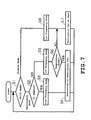
- the control circuit 40 judges at step S1 which mode has been selected.
- the control circuit 40 determines at step S2 whether or not the plug 16 is attached to or received in the jack 17 embedded in the body 11. If the detection signal is supplied from the detection circuit 41, the control circuit 40 confirms the attachment of the plug 16 to the body 11. Since the electric power is supplied to the body 11 from an outlet through the plug 16, the user is allowed to use the notebook-sized personal computer 10 without concern for exhaustion of the supplied electric power.
- the control circuit 40 sets at step S3 the frequency of the clock signal, Which is generated at the clock generator 43, at the first frequency.
- the high frequency mode has accordingly been established in the CPU 18.
- the CPU 18 processes software at the maximum processing speed.
- the control circuit 40 is adapted to activate the ventilation fan 26 at step S4.
- the heat from the CPU 18 can be radiated from both the radiation plate 23 and the fin 24.
- the cooling device 22 achieves a high cooling performance as specified by the first level.
- the heat from the CPU 18 can be efficiently radiated so that rise in temperature around the CPU 18 can be avoided. Since the notebook-sized personal computer 10 receives the electric power from an outlet through the plug 16, the operation of the ventilation fan 26 fails to cause exhaustion of the electric power supplied to the CPU 18. The user may keep operating the notebook-sized personal computer 10 without concern about termination of the supply of the electric power.
- control circuit 40 determines the removal of the plug 16 from the body 11 at step S2
- the control circuit 40 sets at step S5 the frequency of the clock signal, which is generated at the clock generator 43, at the second frequency.
- the low frequency mode has accordingly been established in the CPU 18.
- the CPU 18 receives the electric power only from the secondary battery 21. No electric power is supplied from the plug 18 to the CPU 18.
- the electric power consumed at the CPU 18 directly affects the duration of the supplied electric power from the second battery 21. Drop in the clock frequency to the CPU 18 enables to save the electric power stored in the second battery 21, so that the duration of the operation of the CPU 18 can be extended.
- the control circuit 40 keeps receiving the signal indicating the temperature around the CPU 18 from the thermal sensor 42.
- the control circuit 40 compares at step S6 the temperature detected at the thermal sensor 42 and a predetermined threshold temperature level.
- the threshold temperature level can be set in view of temperature permissible for electronic elements and components in the vicinity of the CPU 18.
- the control circuit 40 keeps the ventilation fan 26 at rest at step S7.
- the cooling performance is set at the second level in the cooling device 22. Since the drop in the clock frequency to the CPU 18 serves to restrain the calorific power generated at the CPU 18 in the low frequency mode, the low cooling performance may sufficiently suppress rise in the temperature around the CPU 18. In addition, no operation leads to no consumption of electric power by the ventilation fan 26, contributing to saving the electrical power stored in the second battery 21.
- the procedure goes to step S4 where the control circuit 40 activates the ventilation fan 26.
- the cooling device 22 achieves the higher cooling performance as defined by the aforementioned first level.
- the heat from the CPU 18 can efficiently be radiated, so that the temperature can drop around the CPU 18.
- the operation of electronic elements and components can be guaranteed in the vicinity of the CPU 18.
- the radiation plate 23 provides a surface area enough to radiate the heat from the CPU 18 operating at the second frequency lower than the first frequency
- the temperature around the CPU 18 can be avoided from exceeding the threshold temperature level.
- the operation of the ventilation fan 26 contributes to dropping the temperature around the CPU 18.
- the intermittent operation of the ventilation fan 26 in this manner may contribute to reduction in the consumption of the electric power at the ventilation fan 26, as compared with the constant operation of the ventilation fan 26.
- the control circuit 40 When the control circuit 40 confirms the designation of the silence mode at step S1, the control circuit 40 then sets at step S8 the frequency of the clock signal, which is generated at the clock generator 43, at the second frequency.
- the low frequency mode has accordingly been established in the CPU 18.
- the CPU 18 operates more slowly, with consequent reduction in heat generation.
- the control circuit 40 keeps the ventilation fan 26 at rest at step S7.
- the cooling performance is set at the second level in the cooling device 22. Since the drop in the clock frequency of the CPU 18 serves to restrain the calorific power generated by the CPU 18, the low cooling performance may sufficiently suppress rise in the temperature around the CPU 18.
- the ventilation fan 26 is maintained at rest in the silence mode irrespective of the supply of the electric power through the plug 16. No operation of the ventilation fan 26, namely, no rotation of the rotor 28 means no fan noise. Accordingly, the user can operate the notebook-sized personal computer 10 with less noise leaking out of the body 11.
- the management of the control circuit 40 in the above manner is preferably realized at intervals during the operation of the notebook-sized personal computer 10. Constant monitoring of the attachment of the plug 16 and variation in temperature around the CPU 18 allows the cooling device 22 to dynamically change its cooling performance in response to variation in the condition of the CPU 18.
- the detection signal supplied to the control circuit 40 may be generated, as shown in Fig. 8, for example, at a switch 46 for detecting a physical contact between the plug 16 and the jack 17.
- the switch 46 may employ a relay switch or a transistor switch, for example.
- the cooling device 22 may change its cooling performance not only by turning on and off the ventilation fan 26 as described above but also by changing revolution speed of the ventilation fan 26 to high or low revolution speeds.
Landscapes
- Engineering & Computer Science (AREA)
- Theoretical Computer Science (AREA)
- Human Computer Interaction (AREA)
- Physics & Mathematics (AREA)
- General Engineering & Computer Science (AREA)
- General Physics & Mathematics (AREA)
- Computer Hardware Design (AREA)
- Cooling Or The Like Of Electrical Apparatus (AREA)
- Power Sources (AREA)
- Cooling Or The Like Of Semiconductors Or Solid State Devices (AREA)
Priority Applications (1)
| Application Number | Priority Date | Filing Date | Title |
|---|---|---|---|
| EP05007330A EP1574933B1 (de) | 1999-02-04 | 1999-12-23 | Kühlvorrichtung und Steuerungsverfahren |
Applications Claiming Priority (2)
| Application Number | Priority Date | Filing Date | Title |
|---|---|---|---|
| JP02764599A JP3258288B2 (ja) | 1999-02-04 | 1999-02-04 | 携帯型電子機器の冷却制御方法および冷却装置 |
| JP2764599 | 1999-02-04 |
Related Child Applications (1)
| Application Number | Title | Priority Date | Filing Date |
|---|---|---|---|
| EP05007330A Division EP1574933B1 (de) | 1999-02-04 | 1999-12-23 | Kühlvorrichtung und Steuerungsverfahren |
Publications (2)
| Publication Number | Publication Date |
|---|---|
| EP1026571A2 true EP1026571A2 (de) | 2000-08-09 |
| EP1026571A3 EP1026571A3 (de) | 2004-02-11 |
Family
ID=12226674
Family Applications (2)
| Application Number | Title | Priority Date | Filing Date |
|---|---|---|---|
| EP99310524A Ceased EP1026571A3 (de) | 1999-02-04 | 1999-12-23 | Kühlvorrichtung und Steuerungsverfahren |
| EP05007330A Expired - Lifetime EP1574933B1 (de) | 1999-02-04 | 1999-12-23 | Kühlvorrichtung und Steuerungsverfahren |
Family Applications After (1)
| Application Number | Title | Priority Date | Filing Date |
|---|---|---|---|
| EP05007330A Expired - Lifetime EP1574933B1 (de) | 1999-02-04 | 1999-12-23 | Kühlvorrichtung und Steuerungsverfahren |
Country Status (7)
| Country | Link |
|---|---|
| US (1) | US6454362B1 (de) |
| EP (2) | EP1026571A3 (de) |
| JP (1) | JP3258288B2 (de) |
| KR (1) | KR100654872B1 (de) |
| CN (2) | CN1198194C (de) |
| DE (1) | DE69940862D1 (de) |
| TW (1) | TW445613B (de) |
Cited By (4)
| Publication number | Priority date | Publication date | Assignee | Title |
|---|---|---|---|---|
| EP1389754A1 (de) * | 2002-08-14 | 2004-02-18 | Enermax, Technology Corporation | Hitze verbreitener Ventilator mit von Hand verstellbarer Geschwindigkeitseinstellung |
| WO2005033917A2 (en) * | 2003-10-01 | 2005-04-14 | Intel Corporation | Reversible two-phase and refrigeration loop |
| US8395898B1 (en) | 2011-03-14 | 2013-03-12 | Dell Products, Lp | System, apparatus and method for cooling electronic components |
| CN104978000A (zh) * | 2015-07-01 | 2015-10-14 | 上海与德通讯技术有限公司 | 散热方法及散热系统 |
Families Citing this family (11)
| Publication number | Priority date | Publication date | Assignee | Title |
|---|---|---|---|---|
| JP3959495B2 (ja) * | 1999-08-31 | 2007-08-15 | 富士通株式会社 | 情報処理装置 |
| US6851064B2 (en) * | 2001-08-22 | 2005-02-01 | Hewlett-Packard Development Company, L.P. | Fine-grained thermal control in memory subsystems |
| KR100693173B1 (ko) * | 2003-11-14 | 2007-03-13 | 엘지전자 주식회사 | 휴대용 컴퓨터의 방열구조 |
| JP4157550B2 (ja) * | 2005-08-30 | 2008-10-01 | 株式会社東芝 | 情報処理装置および冷却制御方法 |
| CN101752843B (zh) * | 2008-12-10 | 2012-06-27 | 纬创资通股份有限公司 | 电子装置的电池保护系统及方法 |
| CN102298431A (zh) * | 2010-06-28 | 2011-12-28 | 鸿富锦精密工业(深圳)有限公司 | 计算机散热控制系统及方法 |
| CN102706063B (zh) * | 2012-06-11 | 2016-12-14 | 罗运山 | 高空冷气采集方法 |
| US10025329B2 (en) * | 2013-08-21 | 2018-07-17 | Google Technology Holdings LLC | Method and apparatus for adjusting portable electronic device operation based on ambient temperature |
| JP2017111725A (ja) * | 2015-12-18 | 2017-06-22 | アズビル株式会社 | 電子機器 |
| JP6469183B2 (ja) | 2017-07-25 | 2019-02-13 | レノボ・シンガポール・プライベート・リミテッド | 電子機器 |
| US11930620B2 (en) * | 2020-06-27 | 2024-03-12 | Intel Corporation | Vapor chambers |
Citations (5)
| Publication number | Priority date | Publication date | Assignee | Title |
|---|---|---|---|---|
| US5485073A (en) * | 1989-12-28 | 1996-01-16 | Kabushiki Kaisha Toshiba | Personal computer for performing charge and switching control of different types of battery packs |
| EP0712064A1 (de) * | 1994-10-11 | 1996-05-15 | Digital Equipment Corporation | Steuerung verstellbarer Taktfrequenz für einen Mikroprozessor verwendende Rechnersysteme |
| JPH08328698A (ja) * | 1995-05-30 | 1996-12-13 | Toshiba Corp | ポータブルコンピュータ |
| US5828549A (en) * | 1996-10-08 | 1998-10-27 | Dell U.S.A., L.P. | Combination heat sink and air duct for cooling processors with a series air flow |
| WO1998052397A1 (en) * | 1997-05-15 | 1998-11-19 | Intel Corporation | A flat fan heat exchanger |
Family Cites Families (11)
| Publication number | Priority date | Publication date | Assignee | Title |
|---|---|---|---|---|
| JPH0293673A (ja) * | 1988-09-30 | 1990-04-04 | Konica Corp | トナーカートリッジ |
| JPH0617294A (ja) * | 1992-07-02 | 1994-01-25 | Kansai Paint Co Ltd | 塗膜形成方法 |
| JP3385482B2 (ja) * | 1993-11-15 | 2003-03-10 | 株式会社日立製作所 | 電子機器 |
| JPH07336904A (ja) * | 1994-06-14 | 1995-12-22 | Sony Corp | 電子機器 |
| US6029119A (en) * | 1996-01-16 | 2000-02-22 | Compaq Computer Corporation | Thermal management of computers |
| KR100260380B1 (ko) | 1996-01-26 | 2000-07-01 | 윤종용 | 마이크로 프로세서칩의 냉각팬 제어장치 및 그 제어방법 |
| JP3142114B2 (ja) * | 1996-06-05 | 2001-03-07 | 株式会社ピーエフユー | 発熱素子の冷却構造 |
| JP3041447B2 (ja) * | 1996-08-29 | 2000-05-15 | 昭和アルミニウム株式会社 | 携帯型電子機器用放熱器 |
| JPH10108052A (ja) * | 1996-09-27 | 1998-04-24 | Sanyo Electric Co Ltd | 電子映像撮影装置 |
| US5862037A (en) * | 1997-03-03 | 1999-01-19 | Inclose Design, Inc. | PC card for cooling a portable computer |
| JPH10303582A (ja) * | 1997-04-22 | 1998-11-13 | Toshiba Corp | 回路モジュールの冷却装置および回路モジュールを搭載した携帯形情報機器 |
-
1999
- 1999-02-04 JP JP02764599A patent/JP3258288B2/ja not_active Expired - Fee Related
- 1999-12-23 EP EP99310524A patent/EP1026571A3/de not_active Ceased
- 1999-12-23 EP EP05007330A patent/EP1574933B1/de not_active Expired - Lifetime
- 1999-12-23 DE DE69940862T patent/DE69940862D1/de not_active Expired - Lifetime
- 1999-12-30 CN CNB991274458A patent/CN1198194C/zh not_active Expired - Fee Related
- 1999-12-30 KR KR1019990065767A patent/KR100654872B1/ko not_active IP Right Cessation
- 1999-12-30 CN CNB03127868XA patent/CN1235114C/zh not_active Expired - Fee Related
- 1999-12-30 US US09/475,773 patent/US6454362B1/en not_active Expired - Fee Related
-
2000
- 2000-02-02 TW TW089101830A patent/TW445613B/zh not_active IP Right Cessation
Patent Citations (5)
| Publication number | Priority date | Publication date | Assignee | Title |
|---|---|---|---|---|
| US5485073A (en) * | 1989-12-28 | 1996-01-16 | Kabushiki Kaisha Toshiba | Personal computer for performing charge and switching control of different types of battery packs |
| EP0712064A1 (de) * | 1994-10-11 | 1996-05-15 | Digital Equipment Corporation | Steuerung verstellbarer Taktfrequenz für einen Mikroprozessor verwendende Rechnersysteme |
| JPH08328698A (ja) * | 1995-05-30 | 1996-12-13 | Toshiba Corp | ポータブルコンピュータ |
| US5828549A (en) * | 1996-10-08 | 1998-10-27 | Dell U.S.A., L.P. | Combination heat sink and air duct for cooling processors with a series air flow |
| WO1998052397A1 (en) * | 1997-05-15 | 1998-11-19 | Intel Corporation | A flat fan heat exchanger |
Non-Patent Citations (1)
| Title |
|---|
| "INTEGRATED HEAT PIPE FAN" IBM TECHNICAL DISCLOSURE BULLETIN, IBM CORP. NEW YORK, US, vol. 38, no. 12, 1 December 1995 (1995-12-01), pages 531-532, XP000588228 ISSN: 0018-8689 * |
Cited By (7)
| Publication number | Priority date | Publication date | Assignee | Title |
|---|---|---|---|---|
| EP1389754A1 (de) * | 2002-08-14 | 2004-02-18 | Enermax, Technology Corporation | Hitze verbreitener Ventilator mit von Hand verstellbarer Geschwindigkeitseinstellung |
| WO2005033917A2 (en) * | 2003-10-01 | 2005-04-14 | Intel Corporation | Reversible two-phase and refrigeration loop |
| WO2005033917A3 (en) * | 2003-10-01 | 2005-08-04 | Intel Corp | Reversible two-phase and refrigeration loop |
| CN100447707C (zh) * | 2003-10-01 | 2008-12-31 | 英特尔公司 | 用于切换可逆的两相和制冷回路的方法和系统 |
| US8395898B1 (en) | 2011-03-14 | 2013-03-12 | Dell Products, Lp | System, apparatus and method for cooling electronic components |
| US8619426B2 (en) | 2011-03-14 | 2013-12-31 | Dell Products, Lp | System, apparatus and method for cooling electronic components |
| CN104978000A (zh) * | 2015-07-01 | 2015-10-14 | 上海与德通讯技术有限公司 | 散热方法及散热系统 |
Also Published As
| Publication number | Publication date |
|---|---|
| US6454362B1 (en) | 2002-09-24 |
| KR20000057119A (ko) | 2000-09-15 |
| CN1515976A (zh) | 2004-07-28 |
| CN1262599A (zh) | 2000-08-09 |
| TW445613B (en) | 2001-07-11 |
| JP2000228594A (ja) | 2000-08-15 |
| DE69940862D1 (de) | 2009-06-18 |
| EP1574933A1 (de) | 2005-09-14 |
| EP1574933B1 (de) | 2009-05-06 |
| CN1235114C (zh) | 2006-01-04 |
| JP3258288B2 (ja) | 2002-02-18 |
| CN1198194C (zh) | 2005-04-20 |
| KR100654872B1 (ko) | 2006-12-08 |
| EP1026571A3 (de) | 2004-02-11 |
Similar Documents
| Publication | Publication Date | Title |
|---|---|---|
| US6454362B1 (en) | Method of controlling cooling device in portable electronic and cooling device therefor | |
| US6275945B1 (en) | Apparatus for radiating heat for use in computer system | |
| US7689846B1 (en) | Method and apparatus for increasing the operating frequency of an electronic circuit | |
| KR940007807B1 (ko) | 전원공급장치 및 접속장치 | |
| US8000099B2 (en) | Power supply cooling system | |
| JP2003067087A (ja) | 可搬型情報処理装置の液冷システム | |
| KR19980020292A (ko) | 휴대용 컴퓨터 | |
| JP3658317B2 (ja) | 冷却方法および冷却システムならびに情報処理装置 | |
| JP2008083841A (ja) | ブレードサーバ、ブレード装置、及びブレードサーバの電力管理方法 | |
| EP2624401B1 (de) | Elektronische Vorrichtung und ihr Antriebs-Steuerverfahren | |
| CN104978000A (zh) | 散热方法及散热系统 | |
| JP2001145274A (ja) | 充電装置を備えた携帯機器 | |
| US7203856B2 (en) | Mobile computer with desktop type processor | |
| US20050046991A1 (en) | Information processing apparatus having function to control housing temperature | |
| JP3391577B2 (ja) | 電源回路 | |
| CN110928392A (zh) | 供电控制装置和电子设备 | |
| JP2953423B2 (ja) | 携帯型情報処理装置 | |
| US8506368B2 (en) | Device and method for enhanced air circulation | |
| JP2008131803A (ja) | 携帯端末装置 | |
| JP2002163042A (ja) | 携帯型情報機器 | |
| JP2001100865A (ja) | 携帯型情報処理装置 | |
| JP2950320B1 (ja) | 情報処理装置及び拡張装置 | |
| JP2000222081A (ja) | 携帯情報処理装置 | |
| KR101070629B1 (ko) | 휴대용 전자기기의 전원공급시스템 및 그 제어방법 | |
| JPH11145666A (ja) | 電子機器 |
Legal Events
| Date | Code | Title | Description |
|---|---|---|---|
| PUAI | Public reference made under article 153(3) epc to a published international application that has entered the european phase |
Free format text: ORIGINAL CODE: 0009012 |
|
| AK | Designated contracting states |
Kind code of ref document: A2 Designated state(s): AT BE CH CY DE DK ES FI FR GB GR IE IT LI LU MC NL PT SE |
|
| AX | Request for extension of the european patent |
Free format text: AL;LT;LV;MK;RO;SI |
|
| PUAL | Search report despatched |
Free format text: ORIGINAL CODE: 0009013 |
|
| AK | Designated contracting states |
Kind code of ref document: A3 Designated state(s): AT BE CH CY DE DK ES FI FR GB GR IE IT LI LU MC NL PT SE |
|
| AX | Request for extension of the european patent |
Extension state: AL LT LV MK RO SI |
|
| 17P | Request for examination filed |
Effective date: 20040806 |
|
| AKX | Designation fees paid |
Designated state(s): DE FR GB |
|
| 17Q | First examination report despatched |
Effective date: 20041117 |
|
| APBN | Date of receipt of notice of appeal recorded |
Free format text: ORIGINAL CODE: EPIDOSNNOA2E |
|
| APBR | Date of receipt of statement of grounds of appeal recorded |
Free format text: ORIGINAL CODE: EPIDOSNNOA3E |
|
| APAF | Appeal reference modified |
Free format text: ORIGINAL CODE: EPIDOSCREFNE |
|
| APAF | Appeal reference modified |
Free format text: ORIGINAL CODE: EPIDOSCREFNE |
|
| APAF | Appeal reference modified |
Free format text: ORIGINAL CODE: EPIDOSCREFNE |
|
| APBT | Appeal procedure closed |
Free format text: ORIGINAL CODE: EPIDOSNNOA9E |
|
| STAA | Information on the status of an ep patent application or granted ep patent |
Free format text: STATUS: THE APPLICATION HAS BEEN REFUSED |
|
| 18R | Application refused |
Effective date: 20110825 |