EP1024557A1 - Abdichtende Membrane für einen wasserdichten Steckverbinder und ein wasserdichter Steckverbinder - Google Patents
Abdichtende Membrane für einen wasserdichten Steckverbinder und ein wasserdichter Steckverbinder Download PDFInfo
- Publication number
- EP1024557A1 EP1024557A1 EP99125517A EP99125517A EP1024557A1 EP 1024557 A1 EP1024557 A1 EP 1024557A1 EP 99125517 A EP99125517 A EP 99125517A EP 99125517 A EP99125517 A EP 99125517A EP 1024557 A1 EP1024557 A1 EP 1024557A1
- Authority
- EP
- European Patent Office
- Prior art keywords
- terminal fitting
- insertion hole
- sealing plug
- slits
- female terminal
- Prior art date
- Legal status (The legal status is an assumption and is not a legal conclusion. Google has not performed a legal analysis and makes no representation as to the accuracy of the status listed.)
- Withdrawn
Links
Images


Classifications
-
- H—ELECTRICITY
- H01—ELECTRIC ELEMENTS
- H01R—ELECTRICALLY-CONDUCTIVE CONNECTIONS; STRUCTURAL ASSOCIATIONS OF A PLURALITY OF MUTUALLY-INSULATED ELECTRICAL CONNECTING ELEMENTS; COUPLING DEVICES; CURRENT COLLECTORS
- H01R13/00—Details of coupling devices of the kinds covered by groups H01R12/70 or H01R24/00 - H01R33/00
- H01R13/46—Bases; Cases
- H01R13/52—Dustproof, splashproof, drip-proof, waterproof, or flameproof cases
- H01R13/5205—Sealing means between cable and housing, e.g. grommet
- H01R13/5208—Sealing means between cable and housing, e.g. grommet having at least two cable receiving openings
-
- H—ELECTRICITY
- H01—ELECTRIC ELEMENTS
- H01R—ELECTRICALLY-CONDUCTIVE CONNECTIONS; STRUCTURAL ASSOCIATIONS OF A PLURALITY OF MUTUALLY-INSULATED ELECTRICAL CONNECTING ELEMENTS; COUPLING DEVICES; CURRENT COLLECTORS
- H01R13/00—Details of coupling devices of the kinds covered by groups H01R12/70 or H01R24/00 - H01R33/00
- H01R13/46—Bases; Cases
- H01R13/502—Bases; Cases composed of different pieces
- H01R13/506—Bases; Cases composed of different pieces assembled by snap action of the parts
Definitions
- the present invention relates to a sealing plug, in particular to a one-piece type rubber plug for a watertight connector and particularly to a rubber plug for a watertight connector through which plug box-shaped terminal fittings are suitably insertable and further particularly to a rubber plug for a watertight connector through which plug terminal fittings having stabilizers are suitably insertable. Furthermore the invention relates to a watertight connector having such a sealing plug.
- a one-piece type waterproof rubber plug is constructed such that it is fittable into an opening in the rear surface of a housing formed with cavities and insertion holes are formed in positions corresponding to the respective cavities.
- a known rubber plug used for box-shaped terminal fittings is disclosed in Japanese Unexamined Patent Publication No. 3-43972.
- This rubber plug is, as schematically shown in FIG. 21, such that the shape of insertion holes 1 is rectangular at an entrance side in conformity with the outer configuration of the terminal fittings 5 and circular at an exit side so that the insertion holes 1 can be held in sealing contact with the outer surfaces of wires 6. Further, hollow escape portions 4 are formed around the circular holes 2.
- an inner portion 3 of the circular hole 2 displaces toward the escape portion 4, thereby preventing the inner surface thereof from being scratched or damaged.
- the inner portion 3 is thinned by forming the escape portion 4 around the circular hole 2 which should come into sealing contact with the outer surface of the wire 6. This results in an insufficient elastic force, which is not necessarily satisfactory in view of sealability.
- terminal fittings have been formed with stabilizers to stabilize the insertion thereof into cavities and prevent an upside-down insertion in recent years. If the terminal fitting provided with a stabilizer is inserted, the inner surface of the insertion hole may be scratched or damaged by the stabilizer, resulting in insufficient sealability.
- the present invention was developed in view of the above problems and an object thereof is to provide a waterproof plug and a watertight connector, which have a high sealability and are prevented from a scratch or damage caused by portions of terminal fittings.
- a sealing plug for a watertight connector into which plug at least one wire having a terminal fitting secured to its end is insertable, wherein the plug is formed with at least one insertion hole which is so engageable with the outer surface of the wire as to substantially prevent the intrusion of water, and wherein one or more slits are formed in the inner surface of the insertion hole preferably in positions corresponding to one or more portions of the terminal fitting.
- the slits extend from the inner peripheral surface of the insertion hole towards the outer periphery of the sealing plug.
- the slits are provided in positions corresponding to corner portions of the terminal fitting.
- a rubber plug for a watertight connector which plug is used by introducing at least one wire having a box-shaped terminal fitting secured to its end therethrough, wherein the plug is formed with at least one round hole which is so engageable with the outer surface of the wire as to prevent the intrusion of water, and slits are formed in the inner surface of the insertion hole in positions corresponding to corner portions of the terminal fitting.
- the corner portions thereof While the terminal fitting is being inserted through the insertion hole, the corner portions thereof enter the slits and advance while elastically forcing the slits to be wider open. After the passage of the terminal fitting, the insertion hole elastically narrows while the slits are closed, thereby coming into sealing contact with the outer surface of the wire.
- the inner surface of the insertion hole is prevented from damages and can be elastically held in sealing contact with the outer surface of the wire over its entire circumference, thereby providing a secure sealing function.
- tapered guide surfaces for guiding the terminal fitting in such a manner that the portions, preferably corner portions, of the terminal fitting are substantially aligned with the slits are formed at an entrance end of the insertion hole.
- the terminal fitting Even if the terminal fitting is slightly displaced in circumferential direction when being pressed against the entrance end of the insertion hole, it is inserted into the insertion hole while the corner portions thereof are guided by the guide surfaces to correct the orientation of the terminal fitting so that the corner portions are aligned with the slits. Since it is not necessary to pay much attention to the orientation of the terminal fitting during the insertion, the terminal fitting can be efficiently inserted.
- the slit is formed in the inner surface of the insertion hole in a position corresponding to a stabilizer of the terminal fitting.
- a rubber plug for a watertight connector which plug is fittable at a rear side of a housing having at least one cavity, and has at least one insertion hole in a position corresponding to the cavity for introducing at least one wire secured to a terminal fitting at its end therethrough, the plug being used by passing the terminal fitting from which a stabilizer for stabilizing the orientation of the terminal fitting during the insertion into the cavity projects therethrough, wherein a slit is formed in the inner surface of the insertion hole in a position corresponding to the stabilizer of the terminal fitting.
- the terminal fitting When the terminal fitting is inserted into the insertion hole with the stabilizer aligned with the slit, it passes through the insertion hole while the stabilizer forcibly enters and advances along the slit. After the passage of the terminal fitting, the insertion hole elastically narrows while the slit is closed, thereby being brought into sealing contact with the outer surface of the wire.
- the terminal fitting By providing the slit for permitting the passage of the stabilizer, the terminal fitting can pass through the insertion hole without damaging or scratching the inner surface of the insertion hole, with the result that secure sealing can be provided between the wire and the insertion hole.
- the terminal fitting having the stabilizer can be used while ensuring sealability, the terminal fitting can be stably inserted into the cavity while the upside-down insertion thereof is prevented.
- At least one tapered guide surface for guiding the terminal fitting to a position where the stabilizer thereof is substantially aligned with the slit is formed at an entrance end of the insertion hole.
- the terminal fitting can be inserted into the insertion hole while being guided by the guide surface to have the orientation thereof corrected to the one where the stabilizer is aligned with the slit. Since it is not necessary to pay much attention to the orientation of the female terminal fitting during the insertion, the terminal fitting can be efficiently inserted.
- the terminal fitting is substantially box-shaped to have corner portions, and corner slits extending substantially radially are formed in the inner surface of the insertion hole in positions corresponding to the corner portions.
- the corner portions thereof When the terminal fitting is passed through the insertion hole, the corner portions thereof enter and advance along the corner slits while elastically forcibly opening them wider. After the passage of the terminal fitting, the insertion hole elastically narrows while the corner slits are closed, thereby being brought into sealing contact with the outer surface of the wire.
- the inner surface of the insertion hole can be prevented from damages and scratches and can be elastically held in sealing contact with the outer surface of the wire over its entire circumference even if the terminal fitting is box-shaped, a sealing function can be securely fulfilled.
- one or more projections or inner lips are provided in an inner portion of the insertion hole to come into substantially close contact with the wire inserted therethrough.
- the sealing property of the sealing plug can be improved.
- one or more outer lips are preferably circumferentially provided on the outer lateral surface of the plug to come into contact with a connector housing.
- the sealing between the housing and the sealing plug can be improved thereby improving the overall sealability of the arrangement.
- the plug is integrally or unitarily formed of rubber.
- a watertight connector comprising:
- the sealing plug is mounted on the connector housing by means of a mounting member.
- FIGS. 1 to 7 One embodiment of the invention is described with reference to FIGS. 1 to 7.
- the invention is applied to a one-piece type waterproof rubber plug used for a female watertight connector.
- This watertight connector includes a waterproof rubber plug 30 provided or providable at the preferably rear side of a female connector housing 10 (hereinafter, female housing 10) for collectively protecting a plurality of wires 18 from water, and a pushing or holding member 20.
- the waterproof rubber plug 30 and the pushing member 20 are successively mounted in this order.
- the female housing 10 is made e.g. of a synthetic resin material and a plurality of cavities 11 for individually accommodating female terminal fittings 14 secured to ends of wires 18 are formed preferably in three stages.
- An unillustrated mating male housing is fittable into a receptacle 19 formed at the front side of the female housing 10 or at an end of the female housing 10 to be mated with the rubber plug 30.
- an opening 12 is formed at the rear end of the female housing 10.
- the waterproof rubber plug 30 and the pushing member 20 are at least partly mounted into or on the opening 12 from behind.
- the waterproof rubber plug 30 has a plurality of lips 31 formed on its outer circumferential surface so as to be held in sealing contact with the inner surface of the opening 12.
- a plurality of insertion holes 32 are formed in positions corresponding to the cavities 11 of the female housing 10.
- the female terminal fittings 14 can be introduced through the insertion holes 32 as described in detail later, and the wires 18 therebehind or connected therewith are or can be held in sealing contact with the inner surfaces of the insertion holes 32.
- the pushing or holding member 20 (mounting member) is so mounted as to push or hold the waterproof rubber plug 30 preferably from behind.
- Locking arms 21 project forward from the lateral or left and right surfaces of the pushing member 20, and are engageable with locking portions 13 projecting from the outer surface of the opening 12 of the female housing 10.
- the pushing member 20 is formed with through holes 22 which can communicate with the insertion holes 32.
- the female terminal fitting 14 is comprised of a substantially box-shaped connection portion 15 provided at the front and two barrel portions 17 provided behind the connection portion 15 to be fastened to an insulating coating and a core of the wire 18 at its end.
- the connection portion 15 preferably has four corner or edge portions 16 by being substantially box-shaped. Further, a connection piece (not shown) connectable with a mating male terminal fitting to be inserted from front is provided in the connection portion 15.
- Each insertion hole 32 is formed round so as to substantially conform to the shape of the wire 18, and penetrates through the waterproof rubber plug 30 to open in the front and rear surfaces thereof as shown in FIG. 3.
- One or more, e.g. three lips or projections 33 are formed on the inner surface of the insertion hole 32 as shown.
- the inner diameter of the lips 33 are set smaller than the outer diameter of the wire 18, so that the lips 33 can be held in sealing contact with the outer surface of the inserted wire 18.
- the guide portion 40 is formed to have a substantially square cross section larger than that of the connection portion 15 of the female terminal fitting 14 at its entrance side, and the inner surface thereof is tapered to preferably have a shape substantially of a truncated rectangular pyramid from the entrance toward the inside.
- the back side of the guide portion 40 communicates with the insertion hole 32.
- the inner surface of the guide portion 40 is made up of four slanted surfaces 41 which gradually project toward the center as the guide portion extends toward the back.
- connection portion 15 can come into contact with oblique sides 42 between the respective slanted surfaces 41 of the guide portion 40 thus formed when the female terminal fitting 14 is substantially properly oriented.
- Slits 50 of a specified depth are formed to extend along the oblique sides 42 up to the front surface of the waterproof rubber plug 30.
- the present invention is constructed as above and a procedure of assembling it is described next.
- the pushing member 20 is mounted by engaging the locking arms 21 thereof with the locking portion 13 of the opening 12 after the waterproof rubber plug 30 is fitted into the opening 12 of the female housing 10. Subsequently, the female terminal fittings 14 fastened to the ends of the wires 18 are inserted into the insertion holes 32 of the waterproof rubber plug 30 after passing through the through holes 22 of the pushing member 20.
- the corner portions 16 of the connection portion 15 are brought into contact with the oblique sides 42 by being guided by the slanted surfaces 41 of the guide portion 40 even if the female terminal fitting 14 is inserted while being slightly circumferentially displaced. Since the orientation of the female terminal fitting 14 is automatically corrected, it is not necessary to pay attention thereto during the insertion.
- the female terminal fitting 14 When the female terminal fitting 14 is further pushed into the insertion hole 32 in a state where the corner portions 16 are in contact with the oblique sides 42 of the guide portion 40, the insertion hole 32 is entirely widened and the corner portions 16 force into the slits 50, thereby opening them wider, and advance along clearances 51 formed there as shown in FIG. 6. Thus, there is no likelihood that the corner portions 16 damage or tear the inner surface of the insertion hole 32, particularly the lips 33 by getting caught thereby.
- the female terminal fitting 14 is or can be at least partly accommodated in the cavity 11 of the female housing 10 located in front after passing through the insertion hole 32.
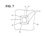
- the wire 18 is introduced into the insertion hole 32 as shown in FIG. 7. Then, the insertion hole 32 widened by the female terminal fitting 14 elastically narrows while the clearances 51 are closed, with the result that the lips 33 are held in sealing contact with the outer surface of the wire 18.
- four fan- or cloverleaf-shaped or trapezoidal portions divided by the slits 50 are compressed radially outward and deformed into flat shape so as to escape the lateral end surfaces in lateral directions.
- the end surfaces of the adjacent fan-shaped portions with the slits 50 therebetween are pressed toward each other to closely abut against each other. Therefore, the lips 33 formed on the inner surface of the insertion hole 32 are held in sealing contact with the outer surface of the wire 18 over its entire circumference, thereby providing secure sealing around the wire 18.
- the slits 50 are formed in the inner surface of each insertion hole 32 of the waterproof rubber plug 30 in conformity with the corner portions 16 of the connection portion 15 of the female terminal fitting 14 according to this embodiment.
- the corner portions 16 are permitted to pass through the insertion hole 32 while forcibly opening the slits 50 wider when the female terminal fitting 14 is passed through the insertion holes 32.
- the slits 50 forcibly opened wider by the insertion of the female terminal fitting 14 are closed as the insertion hole 32 elastically narrows after the passage of the female terminal fitting 14.
- the lips 33 are elastically held substantially in sealing contact with the outer surface of the wire 18, thereby providing a secure sealing function.
- the tapered guide portions 40 is formed at the entrance end of the insertion hole 32, the female terminal fitting 14 is inserted into the insertion hole 32 while being corrected to their proper orientation by the slanted surfaces 41 of the guide portion 40 even if the female terminal fitting 14 is slightly displaced in circumferential direction. Therefore, it is not necessary to pay much attention to the orientation of the female terminal fitting 14 during the insertion, thereby enabling a more efficient inserting operation of the female terminal fitting 14.
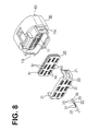
- FIGS. 8 to 15 Another embodiment of the invention is described with reference to FIGS. 8 to 15.
- This watertight connector includes a waterproof rubber plug 30 provided at the rear side of a female connector housing 10 (hereinafter, female housing 10) for collectively protecting a plurality of wires 28 provided with female terminal fittings 23 at their ends from water, and a pushing member 20.
- the waterproof rubber plug 30 and the pushing member 20 are or can be successively mounted in this order.
- the female housing 10 is made e.g. of a synthetic resin material and a plurality of cavities 11 for individually accommodating female terminal fittings 23 secured to ends of wires 28 are formed in three stages.
- An unillustrated mating male housing is fittable into a receptacle 112 formed at the front side of the female housing 10.
- an opening 113 is formed at the rear end of the female housing 10.
- the waterproof rubber plug 30 and the pushing member 20 are or can be mounted into the opening 113 preferably from behind.
- the waterproof rubber plug 30 has a plurality of lips 31 formed on its outer circumferential surface so as to be held in sealing contact with the inner surface of the opening 113.
- a plurality of insertion holes 32 are formed in positions corresponding to the cavities 11 of the female housing 10. The female terminal fittings 23 can be introduced through the insertion holes 32 as described in detail later, and the wires 28 therebehind are held in sealing contact with the inner surfaces of the insertion holes 32.
- the pushing member 20 is so mounted as to push the waterproof rubber plug 30 from behind.
- Locking arms 21 project forward from the left and right surfaces of the pushing member 20, and are engageable with locking portions 114 projecting from the outer surface of the opening 113 of the female housing 10.
- the pushing member 20 is formed with through holes 22 which can substantially communicate with the insertion holes 32, and the female terminal fittings 23 are inserted therethrough preferably from behind.
- a groove for permitting the passage of a stabilizer of the female terminal fitting 23 to be subsequently described is formed at a bottom right portion of each through hole 22.
- the female terminal fitting 23 is comprised of a substantially box-shaped connection portion 24 provided at the front and two barrel portions 27 provided behind the connection portion 24 to be fastened to an insulating coating and a core of the wire 28 at its end.
- a stabilizer 25 projects downward from the lateral or right edge of the bottom surface of the connection portion 24 as shown in FIG. 9.
- the stabilizer 25 is or can be aligned with a groove (not shown) formed in the bottom surface of the cavity 11 when the female terminal 23 is to be inserted into the cavity 11 of the female housing 10.
- the female terminal fitting 23 can be substantially stably inserted by fitting and passing the stabilizer 25 along the groove (see FIG. 8).
- the connection portion 24 has preferably four corner portions 26 by being substantially box-shaped. Further, a connection piece (not shown) connectable with a mating male terminal fitting to be inserted from front is provided in the connection portion 24.
- Each insertion hole 32 preferably is formed substantially round so as to conform to the shape of the wire 28, and penetrates through the waterproof rubber plug 30 to open in the front and rear surfaces thereof as shown in FIGS. 10 and 11.
- Three lips 33 are formed on the inner surface of the insertion hole 32 as shown. The inner diameter of the lips 33 are set smaller than the outer diameter of the wire 28, so that the lips 33 can be held in sealing contact with the outer surface of the inserted wire 28.
- the first guide portion 34 is formed to have a substantially square cross section larger than that of the connection portion 24 of the female terminal fitting 23 at its entrance side, and the inner surface thereof is tapered to preferably have a shape substantially of a truncated rectangular pyramid from the entrance toward the inside.
- the back side of the first guide portion 34 communicates with the insertion hole 32.
- the inner surface of the first guide portion 34 is made up of four slanted surfaces 35 which gradually project toward the center as the guide portion extends toward the back.
- the respective corner portions 26 of the connection portion 24 of the female terminal fitting 23 can come into contact with oblique sides 36 located between the respective slanted surfaces 35 of the first guide portion 34 thus shaped.
- a bottom right portion of the first guide portion 34 is preferably substantially rectangularly recessed downward over a specified width, thereby forming a groove-shaped second guide portion 140.
- the second guide portion 140 is a groove having a triangular horizontal cross section.
- Left and right inner slanted surfaces 141 meet at the back to form a groove bottom 142.
- a slanted surface 143 substantially extends inward from the bottom side of the second guide portion 140.
- the groove bottom 142 extends vertically straight and is provided in a position where the stabilizer 25 can contact it when the female terminal fitting 23 is properly oriented.
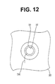
- a slit 150 of a specified depth is formed along the groove bottom 142. The slit 150 is so formed as to substantially communicate with the insertion hole 32 and substantially extends up to the front surface of the waterproof rubber plug 30 as shown in FIG. 12.
- the present invention is constructed as above and a procedure of assembling it is described next.
- the pushing member 20 is mounted by engaging the locking arms 21 thereof with the locking portion 14 of the opening 113 after the waterproof rubber plug 30 is fitted into the opening 113 of the female housing 10. Subsequently, the female terminal fitting 23 fastened to the end of the wire 28 is inserted into the through hole 22 of the pushing member 20 after the stabilizer 25 thereof is substantially aligned with the groove of the through hole 22. The female terminal fitting 23 passed through the through hole 22 is inserted into the insertion hole 32 of the waterproof rubber plug 30.
- the corner portions 26 of the connection portion 24 are guided toward the oblique sides 36 by the slanted surfaces 35 of the first guide portion 34 and the circumferential displacement of the female terminal fitting 23 is substantially corrected.
- the insertion hole 32 is substantially entirely widened and the bottom right corner portion 26 forcibly opens an oblique portion of the slit 150 to enter a clearance 151 formed there as shown in FIG. 14.
- a vertical portion of the slit 150 is also slightly opened as this corner portion 26 advances.
- the stabilizer 25 When the female terminal fitting 23 is further pushed, the stabilizer 25 enters the second guide portion 140. At this time, the female terminal fitting 23 may be circumferentially displaced to a small degree due to a pressure created during the insertion. However, since the stabilizer 25 is guided toward the groove bottom 142 at the back along the slanted surfaces 141 of the second guide portion 140 , it can be securely brought into contact with the groove bottom 142.
- the stabilizer 25 When the female terminal fitting 23 continues to be inserted, the stabilizer 25 enters the already opened slit 150, thereby forcibly opening wider, and passes along the clearance 151 formed there. Thus, there is no likelihood that the stabilizer 25 damages or tears the inner surface of the insertion hole 32, particularly the slips 33 by getting caught.
- the female terminal fitting 23 After passing through the insertion hole 32, the female terminal fitting 23 is accommodated in the corresponding cavity 11 of the female housing 10 located in front. At this time, since the female terminal fitting 23 is moved forward with the stabilizer 25 fitted in the groove of the cavity 11, it can be stably inserted into the cavity 11 and shaking of the female terminal fitting 23 after the insertion can be suppressed.
- the wire 28 is introduced into the insertion hole 32 as shown in FIG. 15. Then, the insertion hole 32 widened by the female terminal fitting 23 elastically narrows while the clearance 151 is substantially tightly closed. As a result, the lips 33 formed on the inner surface of the insertion hole 32 are held in sealing contact with the outer surface of the wire 28 over its substantially entire circumference, thereby providing secure sealing around the wire 28.
- the slit 150 is so formed in the inner surface of each insertion hole 32 of the waterproof rubber plug 30 as to conform to the stabilizer 25 of the connection portion 24 of the female terminal fitting 23 according to this embodiment.
- the stabilizer 25 can pass while forcibly entering the slit 150. This prevents the stabilizer 25 from damaging or scratching the inner surface of the insertion hole 32 by getting caught thereby. Since the female terminal fittings 23 having the stabilizers 25 can be used together with the one-piece type waterproof rubber plug 30 while the sealability of the watertight connector is ensured, the female terminal fittings 23 can be stably inserted into the cavities 11 while the upside-down insertion thereof can be prevented.
- the slit 150 forcibly opened by the insertion of the female terminal fitting 23 is substantially closed as the insertion hole 32 elastically narrows after the passage of the female terminal fitting 23, and the lips 33 are elastically brought into sealing contact with the outer surface of the wire 28, thereby providing a secure sealing function.
- the tapered second guide portion 140 is formed at the entrance end of the insertion hole 32, the female terminal fitting 14 is inserted into the insertion hole 32 while being corrected to their proper orientation by the slanted surfaces 141 of the second guide portions 140 even if the female terminal fittings 14 are slightly displaced in circumferential direction.
- the stabilizer 25 can be securely slipped into the slit 150. Therefore, it is not necessary to pay much attention to the orientation of the female terminal fitting 23 during the insertion, thereby enabling a more efficient inserting operation of the female terminal fitting 23.
- corner slits for permitting the passage of the corner portions of the female terminal fitting are provided.
- the first guide portion 34 is formed with corner slits 152 radially extending along three oblique sides 36 excluding the bottom right one.
- the corner slits 152 are so formed as to have a specified depth and extend up to the front surface of the waterproof rubber plug 30 in the same or similar way as the slit 150 does.
- the corner portions 26 of the connection portion 24 are guided toward the oblique sides 36 by the slanted surfaces 35 of the first guide portion 34, coming into contact with the oblique sides 36.
- the corner portions 26 enter the slit 150 and the corner slits 152, forcibly opening them wider and pass along clearances 151, 153 formed there as shown in FIG. 19.
- the stabilizer 25 passes along the clearance 151 after forcibly entering the slit 150. This prevents the corner portions 26 and the stabilizer 25 from damaging or tearing the inner surface of the insertion hole 32, particularly the lips 33 by getting caught thereby.
- the insertion hole 32 widened by the female terminal fitting 23 elastically narrows while the clearances 151, 153 are tightly closed, thereby providing secure sealing around the wire 28.
Landscapes
- Connector Housings Or Holding Contact Members (AREA)
- Laying Of Electric Cables Or Lines Outside (AREA)
Applications Claiming Priority (4)
| Application Number | Priority Date | Filing Date | Title |
|---|---|---|---|
| JP11022155A JP2000223205A (ja) | 1999-01-29 | 1999-01-29 | 防水コネクタ用ゴム栓 |
| JP2215599 | 1999-01-29 | ||
| JP03812099A JP3463795B2 (ja) | 1999-02-17 | 1999-02-17 | 防水コネクタ用ゴム栓 |
| JP3812099 | 1999-02-17 |
Publications (1)
| Publication Number | Publication Date |
|---|---|
| EP1024557A1 true EP1024557A1 (de) | 2000-08-02 |
Family
ID=26359331
Family Applications (1)
| Application Number | Title | Priority Date | Filing Date |
|---|---|---|---|
| EP99125517A Withdrawn EP1024557A1 (de) | 1999-01-29 | 1999-12-22 | Abdichtende Membrane für einen wasserdichten Steckverbinder und ein wasserdichter Steckverbinder |
Country Status (3)
| Country | Link |
|---|---|
| US (1) | US6250962B1 (de) |
| EP (1) | EP1024557A1 (de) |
| CN (1) | CN1264195A (de) |
Cited By (5)
| Publication number | Priority date | Publication date | Assignee | Title |
|---|---|---|---|---|
| EP1369963A1 (de) * | 2002-06-06 | 2003-12-10 | Sumitomo Wiring Systems, Ltd. | Ein Steckverbinder und ein Verfahren, um einen Anschlusskontakt darin einzupressen |
| EP2233122A2 (de) * | 2003-09-08 | 2010-09-29 | Hill-Rom Services, Inc. | Weste für einen einzigen Patienten |
| EP2306595A1 (de) * | 2008-07-15 | 2011-04-06 | Yazaki Corporation | Wasserdichter steckverbinder |
| EP3057183A1 (de) * | 2015-02-12 | 2016-08-17 | Delphi Technologies, Inc. | Gedichteter Stecker |
| EP3680988A1 (de) * | 2019-01-09 | 2020-07-15 | Delta Electronics (Shanghai) Co., Ltd. | Elektrische vorrichtung mit elektrischer verbindung und schutzfunktion, verbinder und herstellungsverfahren dafür |
Families Citing this family (22)
| Publication number | Priority date | Publication date | Assignee | Title |
|---|---|---|---|---|
| US6478620B1 (en) * | 2000-02-22 | 2002-11-12 | Tyco Electronics Logistics Ag | Electrical connector |
| JP2001267004A (ja) * | 2000-03-21 | 2001-09-28 | Yazaki Corp | コネクタ用防塵カバー及びコネクタの嵌合前防塵構造 |
| JP3804483B2 (ja) * | 2001-05-18 | 2006-08-02 | 住友電装株式会社 | 防水コネクタ |
| JP3767460B2 (ja) | 2001-11-05 | 2006-04-19 | 住友電装株式会社 | 防水コネクタ |
| JP4292803B2 (ja) * | 2003-01-09 | 2009-07-08 | 住友電装株式会社 | 係止解除用治具 |
| WO2005109579A1 (ja) * | 2004-05-10 | 2005-11-17 | Yazaki Corporation | コネクタ部を有するケース部材 |
| TWI350618B (en) * | 2008-08-20 | 2011-10-11 | Pegatron Corp | Electronic device and airproof connector module thereof |
| JP5394821B2 (ja) * | 2009-05-22 | 2014-01-22 | 矢崎総業株式会社 | 防水栓、及び、該防水栓を有するコネクタ |
| JP5403801B2 (ja) * | 2009-07-02 | 2014-01-29 | 矢崎総業株式会社 | フレキシブルフラットケーブルの接続構造及び接続方法 |
| JP5338562B2 (ja) * | 2009-08-21 | 2013-11-13 | 住友電装株式会社 | シールドコネクタ及びワイヤハーネス |
| EP2573823A4 (de) * | 2010-05-20 | 2014-04-30 | Yukita Electric Wire Co Ltd | Verteilerkasten für ein solarzellenmodul |
| JP5454445B2 (ja) * | 2010-10-08 | 2014-03-26 | 住友電装株式会社 | コネクタ |
| CN102328627A (zh) * | 2011-07-28 | 2012-01-25 | 奇瑞汽车股份有限公司 | 一种线束预留插接件堵塞 |
| JP5890985B2 (ja) * | 2011-08-30 | 2016-03-22 | 矢崎総業株式会社 | コネクタ及びこのコネクタに用いられる被覆部材 |
| JP5863179B2 (ja) * | 2012-05-16 | 2016-02-16 | 矢崎総業株式会社 | 防水コネクタ |
| DE102015100763A1 (de) * | 2015-01-20 | 2016-07-21 | Phoenix Contact Gmbh & Co. Kg | Steckverbinderteil mit einer Leitungseinführungseinrichtung |
| JP6536902B2 (ja) * | 2016-02-12 | 2019-07-03 | 住友電装株式会社 | 防水コネクタ |
| US10148033B2 (en) * | 2016-06-01 | 2018-12-04 | Hubbell Incorporated | Water resistant electrical devices |
| US11121498B2 (en) | 2016-06-01 | 2021-09-14 | Hubbell Incorporated | Water resistant electrical devices |
| CN106229705A (zh) * | 2016-09-12 | 2016-12-14 | 珠海凌达压缩机有限公司 | 一种调温设备、压缩机及接线护盖防水结构 |
| CN108953319B (zh) * | 2017-05-22 | 2024-03-08 | 浙江正泰电器股份有限公司 | 连接结构 |
| CN108802435B (zh) * | 2018-04-05 | 2021-06-22 | 安徽天赢电气成套设备制造有限公司 | 一种电力自动化综合测试装置 |
Citations (3)
| Publication number | Priority date | Publication date | Assignee | Title |
|---|---|---|---|---|
| FR2377887A1 (fr) * | 1977-01-24 | 1978-08-18 | Raychem Corp | Objet apte a la reprise thermique |
| US5588856A (en) * | 1991-09-18 | 1996-12-31 | Raychem Corporation | Sealing member and methods of sealing |
| US5766039A (en) * | 1996-04-05 | 1998-06-16 | Yazaki Corporation | Waterproof connector with pressing holes in seal member |
Family Cites Families (4)
| Publication number | Priority date | Publication date | Assignee | Title |
|---|---|---|---|---|
| JPH02204980A (ja) * | 1989-01-25 | 1990-08-14 | Thomas & Betts Corp <T&B> | コネクタ |
| JPH0343972A (ja) | 1989-07-10 | 1991-02-25 | Amp Japan Ltd | 電気コネクタ用防水体 |
| JP2813620B2 (ja) * | 1993-08-06 | 1998-10-22 | 矢崎総業株式会社 | 防水コネクタ |
| US5726392A (en) * | 1997-02-21 | 1998-03-10 | Communications Technology Corporation | Communications housing having grommet assembly |
-
1999
- 1999-12-22 EP EP99125517A patent/EP1024557A1/de not_active Withdrawn
-
2000
- 2000-01-18 US US09/484,711 patent/US6250962B1/en not_active Expired - Fee Related
- 2000-01-20 CN CN00100397A patent/CN1264195A/zh active Pending
Patent Citations (3)
| Publication number | Priority date | Publication date | Assignee | Title |
|---|---|---|---|---|
| FR2377887A1 (fr) * | 1977-01-24 | 1978-08-18 | Raychem Corp | Objet apte a la reprise thermique |
| US5588856A (en) * | 1991-09-18 | 1996-12-31 | Raychem Corporation | Sealing member and methods of sealing |
| US5766039A (en) * | 1996-04-05 | 1998-06-16 | Yazaki Corporation | Waterproof connector with pressing holes in seal member |
Cited By (9)
| Publication number | Priority date | Publication date | Assignee | Title |
|---|---|---|---|---|
| EP1369963A1 (de) * | 2002-06-06 | 2003-12-10 | Sumitomo Wiring Systems, Ltd. | Ein Steckverbinder und ein Verfahren, um einen Anschlusskontakt darin einzupressen |
| US6817904B2 (en) | 2002-06-06 | 2004-11-16 | Sumitomo Wiring Systems, Ltd. | Connector and a method for inserting a terminal fitting thereinto |
| EP2233122A2 (de) * | 2003-09-08 | 2010-09-29 | Hill-Rom Services, Inc. | Weste für einen einzigen Patienten |
| EP2233122A3 (de) * | 2003-09-08 | 2012-06-13 | Hill-Rom Services Pte. Ltd. | Weste für einen einzigen Patienten |
| EP2306595A1 (de) * | 2008-07-15 | 2011-04-06 | Yazaki Corporation | Wasserdichter steckverbinder |
| EP2306595A4 (de) * | 2008-07-15 | 2011-11-23 | Yazaki Corp | Wasserdichter steckverbinder |
| EP3057183A1 (de) * | 2015-02-12 | 2016-08-17 | Delphi Technologies, Inc. | Gedichteter Stecker |
| EP3680988A1 (de) * | 2019-01-09 | 2020-07-15 | Delta Electronics (Shanghai) Co., Ltd. | Elektrische vorrichtung mit elektrischer verbindung und schutzfunktion, verbinder und herstellungsverfahren dafür |
| EP4239809A3 (de) * | 2019-01-09 | 2023-10-25 | Delta Electronics (Shanghai) Co., Ltd | Elektrische vorrichtung mit elektrischer verbindung und schutzfunktion, verbinder und herstellungsverfahren dafür |
Also Published As
| Publication number | Publication date |
|---|---|
| CN1264195A (zh) | 2000-08-23 |
| US6250962B1 (en) | 2001-06-26 |
Similar Documents
| Publication | Publication Date | Title |
|---|---|---|
| EP1024557A1 (de) | Abdichtende Membrane für einen wasserdichten Steckverbinder und ein wasserdichter Steckverbinder | |
| US5967830A (en) | Connector | |
| EP1536527B1 (de) | Wasserdichter Verbinder und Zusammenbauverfahren | |
| US7156698B2 (en) | Waterlight connector | |
| US7338320B2 (en) | Sealing member for watertight connector and a molding method therefor | |
| EP0955697A1 (de) | Wasserdichter Verbinder | |
| EP1587174B1 (de) | Verbinder und Zusammenbau | |
| US6971924B2 (en) | Cap-fitted auxiliary connector for divided connector and a method of assembling such a connector | |
| JPH09147948A (ja) | 電気端子及びそれを使用する電気コネクタ | |
| US8506328B2 (en) | Connector | |
| US8622769B2 (en) | Terminal fitting and fluidproof connector provided therewith | |
| EP0978905B1 (de) | Verbinder | |
| US6386916B1 (en) | Connector | |
| US6679736B2 (en) | Terminal fitting and a connector | |
| US6290554B1 (en) | Female terminal fitting and a female connector | |
| EP1091450B1 (de) | Verbinder | |
| JP2002025675A (ja) | コネクタ | |
| US6247966B1 (en) | Electrical connector with exposed molded latches | |
| EP0942493B1 (de) | Zusammenbau eines wasserdichten Verbinders | |
| US5904593A (en) | Connector with terminal retaining mechanism | |
| JPH09245869A (ja) | 端子係止具付きコネクタ | |
| JPH10144379A (ja) | 端子逆挿入防止構造 | |
| US9065198B2 (en) | Connector with foreign substance entrance preventing portion | |
| JP2000223205A (ja) | 防水コネクタ用ゴム栓 | |
| JPH09129311A (ja) | コネクタの誤挿入防止構造 |
Legal Events
| Date | Code | Title | Description |
|---|---|---|---|
| PUAI | Public reference made under article 153(3) epc to a published international application that has entered the european phase |
Free format text: ORIGINAL CODE: 0009012 |
|
| 17P | Request for examination filed |
Effective date: 20000113 |
|
| AK | Designated contracting states |
Kind code of ref document: A1 Designated state(s): DE FR GB IT |
|
| AX | Request for extension of the european patent |
Free format text: AL;LT;LV;MK;RO;SI |
|
| AKX | Designation fees paid |
Free format text: DE FR GB IT |
|
| 17Q | First examination report despatched |
Effective date: 20011219 |
|
| STAA | Information on the status of an ep patent application or granted ep patent |
Free format text: STATUS: THE APPLICATION IS DEEMED TO BE WITHDRAWN |
|
| 18D | Application deemed to be withdrawn |
Effective date: 20020430 |