EP1024557A1 - A sealing plug for a watertight connector and a watertight connector - Google Patents
A sealing plug for a watertight connector and a watertight connector Download PDFInfo
- Publication number
- EP1024557A1 EP1024557A1 EP99125517A EP99125517A EP1024557A1 EP 1024557 A1 EP1024557 A1 EP 1024557A1 EP 99125517 A EP99125517 A EP 99125517A EP 99125517 A EP99125517 A EP 99125517A EP 1024557 A1 EP1024557 A1 EP 1024557A1
- Authority
- EP
- European Patent Office
- Prior art keywords
- terminal fitting
- insertion hole
- sealing plug
- slits
- female terminal
- Prior art date
- Legal status (The legal status is an assumption and is not a legal conclusion. Google has not performed a legal analysis and makes no representation as to the accuracy of the status listed.)
- Withdrawn
Links
- 238000007789 sealing Methods 0.000 title claims abstract description 59
- 238000003780 insertion Methods 0.000 claims abstract description 128
- 230000037431 insertion Effects 0.000 claims abstract description 128
- XLYOFNOQVPJJNP-UHFFFAOYSA-N water Substances O XLYOFNOQVPJJNP-UHFFFAOYSA-N 0.000 claims abstract description 6
- 239000003381 stabilizer Substances 0.000 claims description 36
- 230000002093 peripheral effect Effects 0.000 claims description 2
- 238000006748 scratching Methods 0.000 abstract description 4
- 230000002393 scratching effect Effects 0.000 abstract description 4
- 230000013011 mating Effects 0.000 description 4
- 241001531957 Opsariichthys uncirostris Species 0.000 description 2
- 239000011248 coating agent Substances 0.000 description 2
- 238000000576 coating method Methods 0.000 description 2
- 238000010276 construction Methods 0.000 description 2
- 239000000463 material Substances 0.000 description 2
- 238000000034 method Methods 0.000 description 2
- 229920003002 synthetic resin Polymers 0.000 description 2
- 239000000057 synthetic resin Substances 0.000 description 2
- 230000001419 dependent effect Effects 0.000 description 1
- 238000006073 displacement reaction Methods 0.000 description 1
- 230000000694 effects Effects 0.000 description 1
- 230000000087 stabilizing effect Effects 0.000 description 1
Images


Classifications
-
- H—ELECTRICITY
- H01—ELECTRIC ELEMENTS
- H01R—ELECTRICALLY-CONDUCTIVE CONNECTIONS; STRUCTURAL ASSOCIATIONS OF A PLURALITY OF MUTUALLY-INSULATED ELECTRICAL CONNECTING ELEMENTS; COUPLING DEVICES; CURRENT COLLECTORS
- H01R13/00—Details of coupling devices of the kinds covered by groups H01R12/70 or H01R24/00 - H01R33/00
- H01R13/46—Bases; Cases
- H01R13/52—Dustproof, splashproof, drip-proof, waterproof, or flameproof cases
- H01R13/5205—Sealing means between cable and housing, e.g. grommet
- H01R13/5208—Sealing means between cable and housing, e.g. grommet having at least two cable receiving openings
-
- H—ELECTRICITY
- H01—ELECTRIC ELEMENTS
- H01R—ELECTRICALLY-CONDUCTIVE CONNECTIONS; STRUCTURAL ASSOCIATIONS OF A PLURALITY OF MUTUALLY-INSULATED ELECTRICAL CONNECTING ELEMENTS; COUPLING DEVICES; CURRENT COLLECTORS
- H01R13/00—Details of coupling devices of the kinds covered by groups H01R12/70 or H01R24/00 - H01R33/00
- H01R13/46—Bases; Cases
- H01R13/502—Bases; Cases composed of different pieces
- H01R13/506—Bases; Cases composed of different pieces assembled by snap action of the parts
Definitions
- the present invention relates to a sealing plug, in particular to a one-piece type rubber plug for a watertight connector and particularly to a rubber plug for a watertight connector through which plug box-shaped terminal fittings are suitably insertable and further particularly to a rubber plug for a watertight connector through which plug terminal fittings having stabilizers are suitably insertable. Furthermore the invention relates to a watertight connector having such a sealing plug.
- a one-piece type waterproof rubber plug is constructed such that it is fittable into an opening in the rear surface of a housing formed with cavities and insertion holes are formed in positions corresponding to the respective cavities.
- a known rubber plug used for box-shaped terminal fittings is disclosed in Japanese Unexamined Patent Publication No. 3-43972.
- This rubber plug is, as schematically shown in FIG. 21, such that the shape of insertion holes 1 is rectangular at an entrance side in conformity with the outer configuration of the terminal fittings 5 and circular at an exit side so that the insertion holes 1 can be held in sealing contact with the outer surfaces of wires 6. Further, hollow escape portions 4 are formed around the circular holes 2.
- an inner portion 3 of the circular hole 2 displaces toward the escape portion 4, thereby preventing the inner surface thereof from being scratched or damaged.
- the inner portion 3 is thinned by forming the escape portion 4 around the circular hole 2 which should come into sealing contact with the outer surface of the wire 6. This results in an insufficient elastic force, which is not necessarily satisfactory in view of sealability.
- terminal fittings have been formed with stabilizers to stabilize the insertion thereof into cavities and prevent an upside-down insertion in recent years. If the terminal fitting provided with a stabilizer is inserted, the inner surface of the insertion hole may be scratched or damaged by the stabilizer, resulting in insufficient sealability.
- the present invention was developed in view of the above problems and an object thereof is to provide a waterproof plug and a watertight connector, which have a high sealability and are prevented from a scratch or damage caused by portions of terminal fittings.
- a sealing plug for a watertight connector into which plug at least one wire having a terminal fitting secured to its end is insertable, wherein the plug is formed with at least one insertion hole which is so engageable with the outer surface of the wire as to substantially prevent the intrusion of water, and wherein one or more slits are formed in the inner surface of the insertion hole preferably in positions corresponding to one or more portions of the terminal fitting.
- the slits extend from the inner peripheral surface of the insertion hole towards the outer periphery of the sealing plug.
- the slits are provided in positions corresponding to corner portions of the terminal fitting.
- a rubber plug for a watertight connector which plug is used by introducing at least one wire having a box-shaped terminal fitting secured to its end therethrough, wherein the plug is formed with at least one round hole which is so engageable with the outer surface of the wire as to prevent the intrusion of water, and slits are formed in the inner surface of the insertion hole in positions corresponding to corner portions of the terminal fitting.
- the corner portions thereof While the terminal fitting is being inserted through the insertion hole, the corner portions thereof enter the slits and advance while elastically forcing the slits to be wider open. After the passage of the terminal fitting, the insertion hole elastically narrows while the slits are closed, thereby coming into sealing contact with the outer surface of the wire.
- the inner surface of the insertion hole is prevented from damages and can be elastically held in sealing contact with the outer surface of the wire over its entire circumference, thereby providing a secure sealing function.
- tapered guide surfaces for guiding the terminal fitting in such a manner that the portions, preferably corner portions, of the terminal fitting are substantially aligned with the slits are formed at an entrance end of the insertion hole.
- the terminal fitting Even if the terminal fitting is slightly displaced in circumferential direction when being pressed against the entrance end of the insertion hole, it is inserted into the insertion hole while the corner portions thereof are guided by the guide surfaces to correct the orientation of the terminal fitting so that the corner portions are aligned with the slits. Since it is not necessary to pay much attention to the orientation of the terminal fitting during the insertion, the terminal fitting can be efficiently inserted.
- the slit is formed in the inner surface of the insertion hole in a position corresponding to a stabilizer of the terminal fitting.
- a rubber plug for a watertight connector which plug is fittable at a rear side of a housing having at least one cavity, and has at least one insertion hole in a position corresponding to the cavity for introducing at least one wire secured to a terminal fitting at its end therethrough, the plug being used by passing the terminal fitting from which a stabilizer for stabilizing the orientation of the terminal fitting during the insertion into the cavity projects therethrough, wherein a slit is formed in the inner surface of the insertion hole in a position corresponding to the stabilizer of the terminal fitting.
- the terminal fitting When the terminal fitting is inserted into the insertion hole with the stabilizer aligned with the slit, it passes through the insertion hole while the stabilizer forcibly enters and advances along the slit. After the passage of the terminal fitting, the insertion hole elastically narrows while the slit is closed, thereby being brought into sealing contact with the outer surface of the wire.
- the terminal fitting By providing the slit for permitting the passage of the stabilizer, the terminal fitting can pass through the insertion hole without damaging or scratching the inner surface of the insertion hole, with the result that secure sealing can be provided between the wire and the insertion hole.
- the terminal fitting having the stabilizer can be used while ensuring sealability, the terminal fitting can be stably inserted into the cavity while the upside-down insertion thereof is prevented.
- At least one tapered guide surface for guiding the terminal fitting to a position where the stabilizer thereof is substantially aligned with the slit is formed at an entrance end of the insertion hole.
- the terminal fitting can be inserted into the insertion hole while being guided by the guide surface to have the orientation thereof corrected to the one where the stabilizer is aligned with the slit. Since it is not necessary to pay much attention to the orientation of the female terminal fitting during the insertion, the terminal fitting can be efficiently inserted.
- the terminal fitting is substantially box-shaped to have corner portions, and corner slits extending substantially radially are formed in the inner surface of the insertion hole in positions corresponding to the corner portions.
- the corner portions thereof When the terminal fitting is passed through the insertion hole, the corner portions thereof enter and advance along the corner slits while elastically forcibly opening them wider. After the passage of the terminal fitting, the insertion hole elastically narrows while the corner slits are closed, thereby being brought into sealing contact with the outer surface of the wire.
- the inner surface of the insertion hole can be prevented from damages and scratches and can be elastically held in sealing contact with the outer surface of the wire over its entire circumference even if the terminal fitting is box-shaped, a sealing function can be securely fulfilled.
- one or more projections or inner lips are provided in an inner portion of the insertion hole to come into substantially close contact with the wire inserted therethrough.
- the sealing property of the sealing plug can be improved.
- one or more outer lips are preferably circumferentially provided on the outer lateral surface of the plug to come into contact with a connector housing.
- the sealing between the housing and the sealing plug can be improved thereby improving the overall sealability of the arrangement.
- the plug is integrally or unitarily formed of rubber.
- a watertight connector comprising:
- the sealing plug is mounted on the connector housing by means of a mounting member.
- FIGS. 1 to 7 One embodiment of the invention is described with reference to FIGS. 1 to 7.
- the invention is applied to a one-piece type waterproof rubber plug used for a female watertight connector.
- This watertight connector includes a waterproof rubber plug 30 provided or providable at the preferably rear side of a female connector housing 10 (hereinafter, female housing 10) for collectively protecting a plurality of wires 18 from water, and a pushing or holding member 20.
- the waterproof rubber plug 30 and the pushing member 20 are successively mounted in this order.
- the female housing 10 is made e.g. of a synthetic resin material and a plurality of cavities 11 for individually accommodating female terminal fittings 14 secured to ends of wires 18 are formed preferably in three stages.
- An unillustrated mating male housing is fittable into a receptacle 19 formed at the front side of the female housing 10 or at an end of the female housing 10 to be mated with the rubber plug 30.
- an opening 12 is formed at the rear end of the female housing 10.
- the waterproof rubber plug 30 and the pushing member 20 are at least partly mounted into or on the opening 12 from behind.
- the waterproof rubber plug 30 has a plurality of lips 31 formed on its outer circumferential surface so as to be held in sealing contact with the inner surface of the opening 12.
- a plurality of insertion holes 32 are formed in positions corresponding to the cavities 11 of the female housing 10.
- the female terminal fittings 14 can be introduced through the insertion holes 32 as described in detail later, and the wires 18 therebehind or connected therewith are or can be held in sealing contact with the inner surfaces of the insertion holes 32.
- the pushing or holding member 20 (mounting member) is so mounted as to push or hold the waterproof rubber plug 30 preferably from behind.
- Locking arms 21 project forward from the lateral or left and right surfaces of the pushing member 20, and are engageable with locking portions 13 projecting from the outer surface of the opening 12 of the female housing 10.
- the pushing member 20 is formed with through holes 22 which can communicate with the insertion holes 32.
- the female terminal fitting 14 is comprised of a substantially box-shaped connection portion 15 provided at the front and two barrel portions 17 provided behind the connection portion 15 to be fastened to an insulating coating and a core of the wire 18 at its end.
- the connection portion 15 preferably has four corner or edge portions 16 by being substantially box-shaped. Further, a connection piece (not shown) connectable with a mating male terminal fitting to be inserted from front is provided in the connection portion 15.
- Each insertion hole 32 is formed round so as to substantially conform to the shape of the wire 18, and penetrates through the waterproof rubber plug 30 to open in the front and rear surfaces thereof as shown in FIG. 3.
- One or more, e.g. three lips or projections 33 are formed on the inner surface of the insertion hole 32 as shown.
- the inner diameter of the lips 33 are set smaller than the outer diameter of the wire 18, so that the lips 33 can be held in sealing contact with the outer surface of the inserted wire 18.
- the guide portion 40 is formed to have a substantially square cross section larger than that of the connection portion 15 of the female terminal fitting 14 at its entrance side, and the inner surface thereof is tapered to preferably have a shape substantially of a truncated rectangular pyramid from the entrance toward the inside.
- the back side of the guide portion 40 communicates with the insertion hole 32.
- the inner surface of the guide portion 40 is made up of four slanted surfaces 41 which gradually project toward the center as the guide portion extends toward the back.
- connection portion 15 can come into contact with oblique sides 42 between the respective slanted surfaces 41 of the guide portion 40 thus formed when the female terminal fitting 14 is substantially properly oriented.
- Slits 50 of a specified depth are formed to extend along the oblique sides 42 up to the front surface of the waterproof rubber plug 30.
- the present invention is constructed as above and a procedure of assembling it is described next.
- the pushing member 20 is mounted by engaging the locking arms 21 thereof with the locking portion 13 of the opening 12 after the waterproof rubber plug 30 is fitted into the opening 12 of the female housing 10. Subsequently, the female terminal fittings 14 fastened to the ends of the wires 18 are inserted into the insertion holes 32 of the waterproof rubber plug 30 after passing through the through holes 22 of the pushing member 20.
- the corner portions 16 of the connection portion 15 are brought into contact with the oblique sides 42 by being guided by the slanted surfaces 41 of the guide portion 40 even if the female terminal fitting 14 is inserted while being slightly circumferentially displaced. Since the orientation of the female terminal fitting 14 is automatically corrected, it is not necessary to pay attention thereto during the insertion.
- the female terminal fitting 14 When the female terminal fitting 14 is further pushed into the insertion hole 32 in a state where the corner portions 16 are in contact with the oblique sides 42 of the guide portion 40, the insertion hole 32 is entirely widened and the corner portions 16 force into the slits 50, thereby opening them wider, and advance along clearances 51 formed there as shown in FIG. 6. Thus, there is no likelihood that the corner portions 16 damage or tear the inner surface of the insertion hole 32, particularly the lips 33 by getting caught thereby.
- the female terminal fitting 14 is or can be at least partly accommodated in the cavity 11 of the female housing 10 located in front after passing through the insertion hole 32.
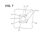
- the wire 18 is introduced into the insertion hole 32 as shown in FIG. 7. Then, the insertion hole 32 widened by the female terminal fitting 14 elastically narrows while the clearances 51 are closed, with the result that the lips 33 are held in sealing contact with the outer surface of the wire 18.
- four fan- or cloverleaf-shaped or trapezoidal portions divided by the slits 50 are compressed radially outward and deformed into flat shape so as to escape the lateral end surfaces in lateral directions.
- the end surfaces of the adjacent fan-shaped portions with the slits 50 therebetween are pressed toward each other to closely abut against each other. Therefore, the lips 33 formed on the inner surface of the insertion hole 32 are held in sealing contact with the outer surface of the wire 18 over its entire circumference, thereby providing secure sealing around the wire 18.
- the slits 50 are formed in the inner surface of each insertion hole 32 of the waterproof rubber plug 30 in conformity with the corner portions 16 of the connection portion 15 of the female terminal fitting 14 according to this embodiment.
- the corner portions 16 are permitted to pass through the insertion hole 32 while forcibly opening the slits 50 wider when the female terminal fitting 14 is passed through the insertion holes 32.
- the slits 50 forcibly opened wider by the insertion of the female terminal fitting 14 are closed as the insertion hole 32 elastically narrows after the passage of the female terminal fitting 14.
- the lips 33 are elastically held substantially in sealing contact with the outer surface of the wire 18, thereby providing a secure sealing function.
- the tapered guide portions 40 is formed at the entrance end of the insertion hole 32, the female terminal fitting 14 is inserted into the insertion hole 32 while being corrected to their proper orientation by the slanted surfaces 41 of the guide portion 40 even if the female terminal fitting 14 is slightly displaced in circumferential direction. Therefore, it is not necessary to pay much attention to the orientation of the female terminal fitting 14 during the insertion, thereby enabling a more efficient inserting operation of the female terminal fitting 14.
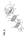
- FIGS. 8 to 15 Another embodiment of the invention is described with reference to FIGS. 8 to 15.
- This watertight connector includes a waterproof rubber plug 30 provided at the rear side of a female connector housing 10 (hereinafter, female housing 10) for collectively protecting a plurality of wires 28 provided with female terminal fittings 23 at their ends from water, and a pushing member 20.
- the waterproof rubber plug 30 and the pushing member 20 are or can be successively mounted in this order.
- the female housing 10 is made e.g. of a synthetic resin material and a plurality of cavities 11 for individually accommodating female terminal fittings 23 secured to ends of wires 28 are formed in three stages.
- An unillustrated mating male housing is fittable into a receptacle 112 formed at the front side of the female housing 10.
- an opening 113 is formed at the rear end of the female housing 10.
- the waterproof rubber plug 30 and the pushing member 20 are or can be mounted into the opening 113 preferably from behind.
- the waterproof rubber plug 30 has a plurality of lips 31 formed on its outer circumferential surface so as to be held in sealing contact with the inner surface of the opening 113.
- a plurality of insertion holes 32 are formed in positions corresponding to the cavities 11 of the female housing 10. The female terminal fittings 23 can be introduced through the insertion holes 32 as described in detail later, and the wires 28 therebehind are held in sealing contact with the inner surfaces of the insertion holes 32.
- the pushing member 20 is so mounted as to push the waterproof rubber plug 30 from behind.
- Locking arms 21 project forward from the left and right surfaces of the pushing member 20, and are engageable with locking portions 114 projecting from the outer surface of the opening 113 of the female housing 10.
- the pushing member 20 is formed with through holes 22 which can substantially communicate with the insertion holes 32, and the female terminal fittings 23 are inserted therethrough preferably from behind.
- a groove for permitting the passage of a stabilizer of the female terminal fitting 23 to be subsequently described is formed at a bottom right portion of each through hole 22.
- the female terminal fitting 23 is comprised of a substantially box-shaped connection portion 24 provided at the front and two barrel portions 27 provided behind the connection portion 24 to be fastened to an insulating coating and a core of the wire 28 at its end.
- a stabilizer 25 projects downward from the lateral or right edge of the bottom surface of the connection portion 24 as shown in FIG. 9.
- the stabilizer 25 is or can be aligned with a groove (not shown) formed in the bottom surface of the cavity 11 when the female terminal 23 is to be inserted into the cavity 11 of the female housing 10.
- the female terminal fitting 23 can be substantially stably inserted by fitting and passing the stabilizer 25 along the groove (see FIG. 8).
- the connection portion 24 has preferably four corner portions 26 by being substantially box-shaped. Further, a connection piece (not shown) connectable with a mating male terminal fitting to be inserted from front is provided in the connection portion 24.
- Each insertion hole 32 preferably is formed substantially round so as to conform to the shape of the wire 28, and penetrates through the waterproof rubber plug 30 to open in the front and rear surfaces thereof as shown in FIGS. 10 and 11.
- Three lips 33 are formed on the inner surface of the insertion hole 32 as shown. The inner diameter of the lips 33 are set smaller than the outer diameter of the wire 28, so that the lips 33 can be held in sealing contact with the outer surface of the inserted wire 28.
- the first guide portion 34 is formed to have a substantially square cross section larger than that of the connection portion 24 of the female terminal fitting 23 at its entrance side, and the inner surface thereof is tapered to preferably have a shape substantially of a truncated rectangular pyramid from the entrance toward the inside.
- the back side of the first guide portion 34 communicates with the insertion hole 32.
- the inner surface of the first guide portion 34 is made up of four slanted surfaces 35 which gradually project toward the center as the guide portion extends toward the back.
- the respective corner portions 26 of the connection portion 24 of the female terminal fitting 23 can come into contact with oblique sides 36 located between the respective slanted surfaces 35 of the first guide portion 34 thus shaped.
- a bottom right portion of the first guide portion 34 is preferably substantially rectangularly recessed downward over a specified width, thereby forming a groove-shaped second guide portion 140.
- the second guide portion 140 is a groove having a triangular horizontal cross section.
- Left and right inner slanted surfaces 141 meet at the back to form a groove bottom 142.
- a slanted surface 143 substantially extends inward from the bottom side of the second guide portion 140.
- the groove bottom 142 extends vertically straight and is provided in a position where the stabilizer 25 can contact it when the female terminal fitting 23 is properly oriented.
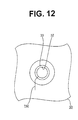
- a slit 150 of a specified depth is formed along the groove bottom 142. The slit 150 is so formed as to substantially communicate with the insertion hole 32 and substantially extends up to the front surface of the waterproof rubber plug 30 as shown in FIG. 12.
- the present invention is constructed as above and a procedure of assembling it is described next.
- the pushing member 20 is mounted by engaging the locking arms 21 thereof with the locking portion 14 of the opening 113 after the waterproof rubber plug 30 is fitted into the opening 113 of the female housing 10. Subsequently, the female terminal fitting 23 fastened to the end of the wire 28 is inserted into the through hole 22 of the pushing member 20 after the stabilizer 25 thereof is substantially aligned with the groove of the through hole 22. The female terminal fitting 23 passed through the through hole 22 is inserted into the insertion hole 32 of the waterproof rubber plug 30.
- the corner portions 26 of the connection portion 24 are guided toward the oblique sides 36 by the slanted surfaces 35 of the first guide portion 34 and the circumferential displacement of the female terminal fitting 23 is substantially corrected.
- the insertion hole 32 is substantially entirely widened and the bottom right corner portion 26 forcibly opens an oblique portion of the slit 150 to enter a clearance 151 formed there as shown in FIG. 14.
- a vertical portion of the slit 150 is also slightly opened as this corner portion 26 advances.
- the stabilizer 25 When the female terminal fitting 23 is further pushed, the stabilizer 25 enters the second guide portion 140. At this time, the female terminal fitting 23 may be circumferentially displaced to a small degree due to a pressure created during the insertion. However, since the stabilizer 25 is guided toward the groove bottom 142 at the back along the slanted surfaces 141 of the second guide portion 140 , it can be securely brought into contact with the groove bottom 142.
- the stabilizer 25 When the female terminal fitting 23 continues to be inserted, the stabilizer 25 enters the already opened slit 150, thereby forcibly opening wider, and passes along the clearance 151 formed there. Thus, there is no likelihood that the stabilizer 25 damages or tears the inner surface of the insertion hole 32, particularly the slips 33 by getting caught.
- the female terminal fitting 23 After passing through the insertion hole 32, the female terminal fitting 23 is accommodated in the corresponding cavity 11 of the female housing 10 located in front. At this time, since the female terminal fitting 23 is moved forward with the stabilizer 25 fitted in the groove of the cavity 11, it can be stably inserted into the cavity 11 and shaking of the female terminal fitting 23 after the insertion can be suppressed.
- the wire 28 is introduced into the insertion hole 32 as shown in FIG. 15. Then, the insertion hole 32 widened by the female terminal fitting 23 elastically narrows while the clearance 151 is substantially tightly closed. As a result, the lips 33 formed on the inner surface of the insertion hole 32 are held in sealing contact with the outer surface of the wire 28 over its substantially entire circumference, thereby providing secure sealing around the wire 28.
- the slit 150 is so formed in the inner surface of each insertion hole 32 of the waterproof rubber plug 30 as to conform to the stabilizer 25 of the connection portion 24 of the female terminal fitting 23 according to this embodiment.
- the stabilizer 25 can pass while forcibly entering the slit 150. This prevents the stabilizer 25 from damaging or scratching the inner surface of the insertion hole 32 by getting caught thereby. Since the female terminal fittings 23 having the stabilizers 25 can be used together with the one-piece type waterproof rubber plug 30 while the sealability of the watertight connector is ensured, the female terminal fittings 23 can be stably inserted into the cavities 11 while the upside-down insertion thereof can be prevented.
- the slit 150 forcibly opened by the insertion of the female terminal fitting 23 is substantially closed as the insertion hole 32 elastically narrows after the passage of the female terminal fitting 23, and the lips 33 are elastically brought into sealing contact with the outer surface of the wire 28, thereby providing a secure sealing function.
- the tapered second guide portion 140 is formed at the entrance end of the insertion hole 32, the female terminal fitting 14 is inserted into the insertion hole 32 while being corrected to their proper orientation by the slanted surfaces 141 of the second guide portions 140 even if the female terminal fittings 14 are slightly displaced in circumferential direction.
- the stabilizer 25 can be securely slipped into the slit 150. Therefore, it is not necessary to pay much attention to the orientation of the female terminal fitting 23 during the insertion, thereby enabling a more efficient inserting operation of the female terminal fitting 23.
- corner slits for permitting the passage of the corner portions of the female terminal fitting are provided.
- the first guide portion 34 is formed with corner slits 152 radially extending along three oblique sides 36 excluding the bottom right one.
- the corner slits 152 are so formed as to have a specified depth and extend up to the front surface of the waterproof rubber plug 30 in the same or similar way as the slit 150 does.
- the corner portions 26 of the connection portion 24 are guided toward the oblique sides 36 by the slanted surfaces 35 of the first guide portion 34, coming into contact with the oblique sides 36.
- the corner portions 26 enter the slit 150 and the corner slits 152, forcibly opening them wider and pass along clearances 151, 153 formed there as shown in FIG. 19.
- the stabilizer 25 passes along the clearance 151 after forcibly entering the slit 150. This prevents the corner portions 26 and the stabilizer 25 from damaging or tearing the inner surface of the insertion hole 32, particularly the lips 33 by getting caught thereby.
- the insertion hole 32 widened by the female terminal fitting 23 elastically narrows while the clearances 151, 153 are tightly closed, thereby providing secure sealing around the wire 28.
Landscapes
- Connector Housings Or Holding Contact Members (AREA)
- Laying Of Electric Cables Or Lines Outside (AREA)
Abstract
To provide a waterproof plug having a high sealing ability which plug is
prevented from damages caused by corner portions of terminal fittings.
A one-piece type waterproof rubber plug 30 is formed with round insertion
holes 32 whose inner surfaces can be held in sealing contact with the outer
surfaces of a plurality of wires 18 individually inserted into the insertion holes 32
to protect them from water. Female terminal fittings 14 having a box-shaped
connection portion 15 are introduced into the insertion holes 32. In the inner
surfaces of the insertion holes 32 are formed slits 50 in positions corresponding to
corner portions 16 of the connection portions 15. While the female terminal
fittings 14 are passing the insertion holes 32 by enlargingly deforming them, the
corner portions 16 enter the slits 50, thereby forcibly opening the slits 50 wider to
form clearances 51. The corner portions 16 advance along the clearances 51.
This prevents the corner portions 16 from damaging or scratching the inner
surfaces of the insertion holes 32. After the passage of the female terminal
fittings 14, the insertion holes 32 elastically narrow to close the clearances 51,
with the result that the lips 33 are held in sealing contact with the outer surfaces
of the wires 18.
Description
- The present invention relates to a sealing plug, in particular to a one-piece type rubber plug for a watertight connector and particularly to a rubber plug for a watertight connector through which plug box-shaped terminal fittings are suitably insertable and further particularly to a rubber plug for a watertight connector through which plug terminal fittings having stabilizers are suitably insertable. Furthermore the invention relates to a watertight connector having such a sealing plug.
- A one-piece type waterproof rubber plug is constructed such that it is fittable into an opening in the rear surface of a housing formed with cavities and insertion holes are formed in positions corresponding to the respective cavities. When a wire connected with a terminal fitting at its end is to be inserted, the terminal fitting is first inserted through the insertion hole while widening it. When the terminal fitting is accommodated in the corresponding cavity after passing the insertion hole, the insertion hole is elastically restored to its original smaller shape to come into sealing contact with the outer surface of the wire, thereby providing secure sealing. If the terminal fitting is box-shaped, the inner surface of the insertion hole may be scratched or damaged by the corner of the box and sealability may not be secured.
- A known rubber plug used for box-shaped terminal fittings is disclosed in Japanese Unexamined Patent Publication No. 3-43972. This rubber plug is, as schematically shown in FIG. 21, such that the shape of insertion holes 1 is rectangular at an entrance side in conformity with the outer configuration of the
terminal fittings 5 and circular at an exit side so that the insertion holes 1 can be held in sealing contact with the outer surfaces ofwires 6. Further,hollow escape portions 4 are formed around thecircular holes 2. - Accordingly, when a box-
shaped terminal fitting 5 is inserted, aninner portion 3 of thecircular hole 2 displaces toward theescape portion 4, thereby preventing the inner surface thereof from being scratched or damaged. - In the prior art construction, the
inner portion 3 is thinned by forming theescape portion 4 around thecircular hole 2 which should come into sealing contact with the outer surface of thewire 6. This results in an insufficient elastic force, which is not necessarily satisfactory in view of sealability. - Moreover, many terminal fittings have been formed with stabilizers to stabilize the insertion thereof into cavities and prevent an upside-down insertion in recent years. If the terminal fitting provided with a stabilizer is inserted, the inner surface of the insertion hole may be scratched or damaged by the stabilizer, resulting in insufficient sealability.
- This causes a problem that the terminal fittings having stabilizers cannot be used when the one-piece type rubber plug is used.
- The present invention was developed in view of the above problems and an object thereof is to provide a waterproof plug and a watertight connector, which have a high sealability and are prevented from a scratch or damage caused by portions of terminal fittings.
- This object is solved according to the invention by a sealing plug according to claim 1 and by a waterproof connector according to
claim 10. Preferred embodiments of the invention are subject of the dependent claims. - According to the invention, there is provided a sealing plug for a watertight connector, into which plug at least one wire having a terminal fitting secured to its end is insertable,
wherein the plug is formed with at least one insertion hole which is so engageable with the outer surface of the wire as to substantially prevent the intrusion of water, and wherein one or more slits are formed in the inner surface of the insertion hole preferably in positions corresponding to one or more portions of the terminal fitting. - According to a preferred embodiment, the slits extend from the inner peripheral surface of the insertion hole towards the outer periphery of the sealing plug.
- According to a further preferred embodiment, the slits are provided in positions corresponding to corner portions of the terminal fitting.
- According to a further preferred embodiment of the invention, there is provided a rubber plug for a watertight connector, which plug is used by introducing at least one wire having a box-shaped terminal fitting secured to its end therethrough,
wherein the plug is formed with at least one round hole which is so engageable with the outer surface of the wire as to prevent the intrusion of water, and slits are formed in the inner surface of the insertion hole in positions corresponding to corner portions of the terminal fitting. - While the terminal fitting is being inserted through the insertion hole, the corner portions thereof enter the slits and advance while elastically forcing the slits to be wider open. After the passage of the terminal fitting, the insertion hole elastically narrows while the slits are closed, thereby coming into sealing contact with the outer surface of the wire.
- Thus, even if the terminal fitting is box-shaped, the inner surface of the insertion hole is prevented from damages and can be elastically held in sealing contact with the outer surface of the wire over its entire circumference, thereby providing a secure sealing function.
- Preferably, tapered guide surfaces for guiding the terminal fitting in such a manner that the portions, preferably corner portions, of the terminal fitting are substantially aligned with the slits are formed at an entrance end of the insertion hole.
- Even if the terminal fitting is slightly displaced in circumferential direction when being pressed against the entrance end of the insertion hole, it is inserted into the insertion hole while the corner portions thereof are guided by the guide surfaces to correct the orientation of the terminal fitting so that the corner portions are aligned with the slits. Since it is not necessary to pay much attention to the orientation of the terminal fitting during the insertion, the terminal fitting can be efficiently inserted.
- Further preferably, the slit is formed in the inner surface of the insertion hole in a position corresponding to a stabilizer of the terminal fitting.
- According to a further preferred embodiment, there is provided a rubber plug for a watertight connector, which plug is fittable at a rear side of a housing having at least one cavity, and has at least one insertion hole in a position corresponding to the cavity for introducing at least one wire secured to a terminal fitting at its end therethrough, the plug being used by passing the terminal fitting from which a stabilizer for stabilizing the orientation of the terminal fitting during the insertion into the cavity projects therethrough, wherein a slit is formed in the inner surface of the insertion hole in a position corresponding to the stabilizer of the terminal fitting.
- When the terminal fitting is inserted into the insertion hole with the stabilizer aligned with the slit, it passes through the insertion hole while the stabilizer forcibly enters and advances along the slit. After the passage of the terminal fitting, the insertion hole elastically narrows while the slit is closed, thereby being brought into sealing contact with the outer surface of the wire.
- By providing the slit for permitting the passage of the stabilizer, the terminal fitting can pass through the insertion hole without damaging or scratching the inner surface of the insertion hole, with the result that secure sealing can be provided between the wire and the insertion hole. For the watertight connector, since the terminal fitting having the stabilizer can be used while ensuring sealability, the terminal fitting can be stably inserted into the cavity while the upside-down insertion thereof is prevented.
- Preferably, at least one tapered guide surface for guiding the terminal fitting to a position where the stabilizer thereof is substantially aligned with the slit is formed at an entrance end of the insertion hole.
- Even if the orientation of the terminal fitting is slightly displaced when the terminal fitting is pressed against the entrance end of the insertion hole, the terminal fitting can be inserted into the insertion hole while being guided by the guide surface to have the orientation thereof corrected to the one where the stabilizer is aligned with the slit. Since it is not necessary to pay much attention to the orientation of the female terminal fitting during the insertion, the terminal fitting can be efficiently inserted.
- Further preferably, the terminal fitting is substantially box-shaped to have corner portions, and corner slits extending substantially radially are formed in the inner surface of the insertion hole in positions corresponding to the corner portions.
- When the terminal fitting is passed through the insertion hole, the corner portions thereof enter and advance along the corner slits while elastically forcibly opening them wider. After the passage of the terminal fitting, the insertion hole elastically narrows while the corner slits are closed, thereby being brought into sealing contact with the outer surface of the wire.
- Since the inner surface of the insertion hole can be prevented from damages and scratches and can be elastically held in sealing contact with the outer surface of the wire over its entire circumference even if the terminal fitting is box-shaped, a sealing function can be securely fulfilled.
- Still further preferably, one or more projections or inner lips are provided in an inner portion of the insertion hole to come into substantially close contact with the wire inserted therethrough.
- Accordingly, the sealing property of the sealing plug can be improved.
- Still further preferably, one or more outer lips are preferably circumferentially provided on the outer lateral surface of the plug to come into contact with a connector housing.
- Accordingly, the sealing between the housing and the sealing plug can be improved thereby improving the overall sealability of the arrangement.
- Most preferably, the plug is integrally or unitarily formed of rubber.
- According to the invention, there is further provided a watertight connector comprising:
- a connector housing having one or more cavities for accommodating one or more terminal fittings;
- at least one sealing plug according to the invention positionable in a receptacle of the connector housing,
- wherein the sealing plug can come into substantially sealing engagement with one or more wires connected with the terminal fittings.
-
- According to a preferred embodiment, the sealing plug is mounted on the connector housing by means of a mounting member.
- These and other objects, features and advantages of the present invention will become more apparent upon a reading of the following detailed description and accompanying drawings in which:
- FIG. 1 is an exploded perspective view of a female watertight connector according to one embodiment of the invention,
- FIG. 2 is an enlarged perspective view showing a waterproof rubber plug and a female terminal fitting,
- FIG. 3 is a side view partly in section along X-X of FIG. 2,
- FIG. 4 is a rear view of the waterproof rubber plug,
- FIG. 5 is a front view showing a state where the female terminal fitting is in contact with a guide portion while being circumferentially displaced,
- FIG. 6 is a front view showing a state where slits are forcibly opened wider by corner portions,
- FIG. 7 is a front view showing a state where a wire is inserted into an insertion hole,
- FIG. is an exploded perspective view of a watertight connector according to another embodiment of the invention,
- FIG. 9 is an enlarged perspective view showing a waterproof rubber plug and a female terminal fitting,
- FIG. 10 is a front view of the waterproof rubber plug,
- FIG. 11 is a side view partly in section along X-X of FIG. 10,
- FIG. 12 is a rear view of the waterproof rubber plug,
- FIG. 13 is a front view showing a state where the female terminal fitting is in contact with a first guide portion while being substantially circumferentially displaced,
- FIG. 14 is a front view showing a state where a connection portion of the female terminal fitting is inserted in an insertion hole,
- FIG. 15 is a front view showing a state where a wire is inserted in the insertion hole,
- FIG. 16 is a front view of a waterproof rubber plug according to still another embodiment of the invention,
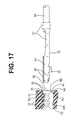
- FIG. 17 is a side view partly in section along Y-Y of FIG. 16,
- FIG. 18 is a rear view of the waterproof plug,
- FIG. 19 is a front view showing a state where a connection portion of the female terminal fitting is inserted in an insertion hole, and
- FIG. 20 is a front view showing a state where a wire is inserted in the insertion hole.
- FIG. 21 is a side view partly in section showing a prior art rubber plug.
-
- One embodiment of the invention is described with reference to FIGS. 1 to 7. The invention is applied to a one-piece type waterproof rubber plug used for a female watertight connector. This watertight connector includes a
waterproof rubber plug 30 provided or providable at the preferably rear side of a female connector housing 10 (hereinafter, female housing 10) for collectively protecting a plurality ofwires 18 from water, and a pushing or holdingmember 20. Thewaterproof rubber plug 30 and the pushingmember 20 are successively mounted in this order. - The
female housing 10 is made e.g. of a synthetic resin material and a plurality ofcavities 11 for individually accommodating femaleterminal fittings 14 secured to ends ofwires 18 are formed preferably in three stages. An unillustrated mating male housing is fittable into areceptacle 19 formed at the front side of thefemale housing 10 or at an end of thefemale housing 10 to be mated with therubber plug 30. On the other hand, anopening 12 is formed at the rear end of thefemale housing 10. Thewaterproof rubber plug 30 and the pushingmember 20 are at least partly mounted into or on theopening 12 from behind. - The
waterproof rubber plug 30 has a plurality oflips 31 formed on its outer circumferential surface so as to be held in sealing contact with the inner surface of theopening 12. On the other hand, a plurality of insertion holes 32 are formed in positions corresponding to thecavities 11 of thefemale housing 10. The femaleterminal fittings 14 can be introduced through the insertion holes 32 as described in detail later, and thewires 18 therebehind or connected therewith are or can be held in sealing contact with the inner surfaces of the insertion holes 32. - The pushing or holding member 20 (mounting member) is so mounted as to push or hold the
waterproof rubber plug 30 preferably from behind. Lockingarms 21 project forward from the lateral or left and right surfaces of the pushingmember 20, and are engageable with lockingportions 13 projecting from the outer surface of theopening 12 of thefemale housing 10. The pushingmember 20 is formed with throughholes 22 which can communicate with the insertion holes 32. - The female terminal fitting 14 is comprised of a substantially box-shaped
connection portion 15 provided at the front and twobarrel portions 17 provided behind theconnection portion 15 to be fastened to an insulating coating and a core of thewire 18 at its end. Theconnection portion 15 preferably has four corner oredge portions 16 by being substantially box-shaped. Further, a connection piece (not shown) connectable with a mating male terminal fitting to be inserted from front is provided in theconnection portion 15. - The insertion holes 32 of the
waterproof rubber plug 30 are described in detail next. Eachinsertion hole 32 is formed round so as to substantially conform to the shape of thewire 18, and penetrates through thewaterproof rubber plug 30 to open in the front and rear surfaces thereof as shown in FIG. 3. One or more, e.g. three lips orprojections 33 are formed on the inner surface of theinsertion hole 32 as shown. The inner diameter of thelips 33 are set smaller than the outer diameter of thewire 18, so that thelips 33 can be held in sealing contact with the outer surface of the insertedwire 18. - At the rear end of the
insertion hole 32 of thewaterproof rubber plug 30 is provided aguide portion 40 as shown in FIG. 2. Theguide portion 40 is formed to have a substantially square cross section larger than that of theconnection portion 15 of the female terminal fitting 14 at its entrance side, and the inner surface thereof is tapered to preferably have a shape substantially of a truncated rectangular pyramid from the entrance toward the inside. The back side of theguide portion 40 communicates with theinsertion hole 32. In other words, the inner surface of theguide portion 40 is made up of four slantedsurfaces 41 which gradually project toward the center as the guide portion extends toward the back. - The
respective corner portions 16 of theconnection portion 15 can come into contact withoblique sides 42 between the respectiveslanted surfaces 41 of theguide portion 40 thus formed when the female terminal fitting 14 is substantially properly oriented.Slits 50 of a specified depth are formed to extend along the oblique sides 42 up to the front surface of thewaterproof rubber plug 30. - The present invention is constructed as above and a procedure of assembling it is described next.
- First, as shown in FIG. 1, the pushing
member 20 is mounted by engaging the lockingarms 21 thereof with the lockingportion 13 of theopening 12 after thewaterproof rubber plug 30 is fitted into theopening 12 of thefemale housing 10. Subsequently, the femaleterminal fittings 14 fastened to the ends of thewires 18 are inserted into the insertion holes 32 of thewaterproof rubber plug 30 after passing through the throughholes 22 of the pushingmember 20. - At this time, since the
guide portion 40 is provided at the entrance end of eachinsertion hole 32, thecorner portions 16 of theconnection portion 15 are brought into contact with the oblique sides 42 by being guided by the slanted surfaces 41 of theguide portion 40 even if the female terminal fitting 14 is inserted while being slightly circumferentially displaced. Since the orientation of the female terminal fitting 14 is automatically corrected, it is not necessary to pay attention thereto during the insertion. - When the female terminal fitting 14 is further pushed into the
insertion hole 32 in a state where thecorner portions 16 are in contact with the oblique sides 42 of theguide portion 40, theinsertion hole 32 is entirely widened and thecorner portions 16 force into theslits 50, thereby opening them wider, and advance alongclearances 51 formed there as shown in FIG. 6. Thus, there is no likelihood that thecorner portions 16 damage or tear the inner surface of theinsertion hole 32, particularly thelips 33 by getting caught thereby. The female terminal fitting 14 is or can be at least partly accommodated in thecavity 11 of thefemale housing 10 located in front after passing through theinsertion hole 32. - After the female terminal fitting 14 passes, the
wire 18 is introduced into theinsertion hole 32 as shown in FIG. 7. Then, theinsertion hole 32 widened by the female terminal fitting 14 elastically narrows while theclearances 51 are closed, with the result that thelips 33 are held in sealing contact with the outer surface of thewire 18. At this time, four fan- or cloverleaf-shaped or trapezoidal portions divided by theslits 50 are compressed radially outward and deformed into flat shape so as to escape the lateral end surfaces in lateral directions. Thus, the end surfaces of the adjacent fan-shaped portions with theslits 50 therebetween are pressed toward each other to closely abut against each other. Therefore, thelips 33 formed on the inner surface of theinsertion hole 32 are held in sealing contact with the outer surface of thewire 18 over its entire circumference, thereby providing secure sealing around thewire 18. - As described above, the
slits 50 are formed in the inner surface of eachinsertion hole 32 of thewaterproof rubber plug 30 in conformity with thecorner portions 16 of theconnection portion 15 of the female terminal fitting 14 according to this embodiment. Thus, thecorner portions 16 are permitted to pass through theinsertion hole 32 while forcibly opening theslits 50 wider when the female terminal fitting 14 is passed through the insertion holes 32. This prevents thecorner portions 16 from scratching or damaging the inner surface of theinsertion hole 32 by getting caught thereby. Theslits 50 forcibly opened wider by the insertion of the female terminal fitting 14 are closed as theinsertion hole 32 elastically narrows after the passage of the female terminal fitting 14. As a result, thelips 33 are elastically held substantially in sealing contact with the outer surface of thewire 18, thereby providing a secure sealing function. - Further, since the tapered
guide portions 40 is formed at the entrance end of theinsertion hole 32, the female terminal fitting 14 is inserted into theinsertion hole 32 while being corrected to their proper orientation by the slanted surfaces 41 of theguide portion 40 even if the female terminal fitting 14 is slightly displaced in circumferential direction. Therefore, it is not necessary to pay much attention to the orientation of the female terminal fitting 14 during the insertion, thereby enabling a more efficient inserting operation of the female terminal fitting 14. - Another embodiment of the invention is described with reference to FIGS. 8 to 15. In this embodiment is illustrated a case where female terminal fittings having stabilizers are inserted through a one-piece type waterproof rubber plug used for a female watertight connector. This watertight connector includes a
waterproof rubber plug 30 provided at the rear side of a female connector housing 10 (hereinafter, female housing 10) for collectively protecting a plurality ofwires 28 provided with femaleterminal fittings 23 at their ends from water, and a pushingmember 20. Thewaterproof rubber plug 30 and the pushingmember 20 are or can be successively mounted in this order. - The
female housing 10 is made e.g. of a synthetic resin material and a plurality ofcavities 11 for individually accommodating femaleterminal fittings 23 secured to ends ofwires 28 are formed in three stages. An unillustrated mating male housing is fittable into areceptacle 112 formed at the front side of thefemale housing 10. On the other hand, anopening 113 is formed at the rear end of thefemale housing 10. Thewaterproof rubber plug 30 and the pushingmember 20 are or can be mounted into theopening 113 preferably from behind. - The
waterproof rubber plug 30 has a plurality oflips 31 formed on its outer circumferential surface so as to be held in sealing contact with the inner surface of theopening 113. On the other hand, a plurality of insertion holes 32 are formed in positions corresponding to thecavities 11 of thefemale housing 10. The femaleterminal fittings 23 can be introduced through the insertion holes 32 as described in detail later, and thewires 28 therebehind are held in sealing contact with the inner surfaces of the insertion holes 32. - The pushing
member 20 is so mounted as to push the waterproof rubber plug 30 from behind. Lockingarms 21 project forward from the left and right surfaces of the pushingmember 20, and are engageable with lockingportions 114 projecting from the outer surface of theopening 113 of thefemale housing 10. The pushingmember 20 is formed with throughholes 22 which can substantially communicate with the insertion holes 32, and the femaleterminal fittings 23 are inserted therethrough preferably from behind. A groove for permitting the passage of a stabilizer of the female terminal fitting 23 to be subsequently described is formed at a bottom right portion of each throughhole 22. - The female terminal fitting 23 is comprised of a substantially box-shaped
connection portion 24 provided at the front and twobarrel portions 27 provided behind theconnection portion 24 to be fastened to an insulating coating and a core of thewire 28 at its end. Astabilizer 25 projects downward from the lateral or right edge of the bottom surface of theconnection portion 24 as shown in FIG. 9. Thestabilizer 25 is or can be aligned with a groove (not shown) formed in the bottom surface of thecavity 11 when thefemale terminal 23 is to be inserted into thecavity 11 of thefemale housing 10. The female terminal fitting 23 can be substantially stably inserted by fitting and passing thestabilizer 25 along the groove (see FIG. 8). Theconnection portion 24 has preferably fourcorner portions 26 by being substantially box-shaped. Further, a connection piece (not shown) connectable with a mating male terminal fitting to be inserted from front is provided in theconnection portion 24. - The insertion holes 32 of the
waterproof rubber plug 30 are described in detail next. Eachinsertion hole 32 preferably is formed substantially round so as to conform to the shape of thewire 28, and penetrates through thewaterproof rubber plug 30 to open in the front and rear surfaces thereof as shown in FIGS. 10 and 11. Threelips 33 are formed on the inner surface of theinsertion hole 32 as shown. The inner diameter of thelips 33 are set smaller than the outer diameter of thewire 28, so that thelips 33 can be held in sealing contact with the outer surface of the insertedwire 28. - At the rear end of the
insertion hole 32 of thewaterproof rubber plug 30 is provided afirst guide portion 34 as shown in FIGS. 9 to 11. Thefirst guide portion 34 is formed to have a substantially square cross section larger than that of theconnection portion 24 of the female terminal fitting 23 at its entrance side, and the inner surface thereof is tapered to preferably have a shape substantially of a truncated rectangular pyramid from the entrance toward the inside. The back side of thefirst guide portion 34 communicates with theinsertion hole 32. In other words, the inner surface of thefirst guide portion 34 is made up of four slantedsurfaces 35 which gradually project toward the center as the guide portion extends toward the back. Therespective corner portions 26 of theconnection portion 24 of the female terminal fitting 23 can come into contact withoblique sides 36 located between the respectiveslanted surfaces 35 of thefirst guide portion 34 thus shaped. - A bottom right portion of the
first guide portion 34 is preferably substantially rectangularly recessed downward over a specified width, thereby forming a groove-shapedsecond guide portion 140. Thesecond guide portion 140 is a groove having a triangular horizontal cross section. Left and right innerslanted surfaces 141 meet at the back to form agroove bottom 142. Further, aslanted surface 143 substantially extends inward from the bottom side of thesecond guide portion 140. Thegroove bottom 142 extends vertically straight and is provided in a position where thestabilizer 25 can contact it when the female terminal fitting 23 is properly oriented. Aslit 150 of a specified depth is formed along thegroove bottom 142. Theslit 150 is so formed as to substantially communicate with theinsertion hole 32 and substantially extends up to the front surface of thewaterproof rubber plug 30 as shown in FIG. 12. - The present invention is constructed as above and a procedure of assembling it is described next.
- First, as shown in FIG. 8, the pushing
member 20 is mounted by engaging the lockingarms 21 thereof with the lockingportion 14 of theopening 113 after thewaterproof rubber plug 30 is fitted into theopening 113 of thefemale housing 10. Subsequently, the female terminal fitting 23 fastened to the end of thewire 28 is inserted into the throughhole 22 of the pushingmember 20 after thestabilizer 25 thereof is substantially aligned with the groove of the throughhole 22. The female terminal fitting 23 passed through the throughhole 22 is inserted into theinsertion hole 32 of thewaterproof rubber plug 30. - At this time, even if the female terminal fitting 23 is inserted into the
insertion hole 32 while being slightly circumferentially displaced as shown by phantom line in FIG. 13, thecorner portions 26 of theconnection portion 24 are guided toward the oblique sides 36 by the slanted surfaces 35 of thefirst guide portion 34 and the circumferential displacement of the female terminal fitting 23 is substantially corrected. When the female terminal fitting 23 is pushed further into theinsertion hole 32, theinsertion hole 32 is substantially entirely widened and the bottomright corner portion 26 forcibly opens an oblique portion of theslit 150 to enter aclearance 151 formed there as shown in FIG. 14. A vertical portion of theslit 150 is also slightly opened as thiscorner portion 26 advances. - When the female terminal fitting 23 is further pushed, the
stabilizer 25 enters thesecond guide portion 140. At this time, the female terminal fitting 23 may be circumferentially displaced to a small degree due to a pressure created during the insertion. However, since thestabilizer 25 is guided toward thegroove bottom 142 at the back along the slantedsurfaces 141 of thesecond guide portion 140 , it can be securely brought into contact with thegroove bottom 142. - When the female terminal fitting 23 continues to be inserted, the
stabilizer 25 enters the already opened slit 150, thereby forcibly opening wider, and passes along theclearance 151 formed there. Thus, there is no likelihood that thestabilizer 25 damages or tears the inner surface of theinsertion hole 32, particularly theslips 33 by getting caught. After passing through theinsertion hole 32, the female terminal fitting 23 is accommodated in the correspondingcavity 11 of thefemale housing 10 located in front. At this time, since the female terminal fitting 23 is moved forward with thestabilizer 25 fitted in the groove of thecavity 11, it can be stably inserted into thecavity 11 and shaking of the female terminal fitting 23 after the insertion can be suppressed. - After the passage of the female terminal fitting 23, the
wire 28 is introduced into theinsertion hole 32 as shown in FIG. 15. Then, theinsertion hole 32 widened by the female terminal fitting 23 elastically narrows while theclearance 151 is substantially tightly closed. As a result, thelips 33 formed on the inner surface of theinsertion hole 32 are held in sealing contact with the outer surface of thewire 28 over its substantially entire circumference, thereby providing secure sealing around thewire 28. - As described above, the
slit 150 is so formed in the inner surface of eachinsertion hole 32 of thewaterproof rubber plug 30 as to conform to thestabilizer 25 of theconnection portion 24 of the female terminal fitting 23 according to this embodiment. Thus, during the insertion of the female terminal fitting 23 through theinsertion hole 32, thestabilizer 25 can pass while forcibly entering theslit 150. This prevents thestabilizer 25 from damaging or scratching the inner surface of theinsertion hole 32 by getting caught thereby. Since the femaleterminal fittings 23 having thestabilizers 25 can be used together with the one-piece typewaterproof rubber plug 30 while the sealability of the watertight connector is ensured, the femaleterminal fittings 23 can be stably inserted into thecavities 11 while the upside-down insertion thereof can be prevented. Further, theslit 150 forcibly opened by the insertion of the female terminal fitting 23 is substantially closed as theinsertion hole 32 elastically narrows after the passage of the female terminal fitting 23, and thelips 33 are elastically brought into sealing contact with the outer surface of thewire 28, thereby providing a secure sealing function. - Further, since the tapered
second guide portion 140 is formed at the entrance end of theinsertion hole 32, the female terminal fitting 14 is inserted into theinsertion hole 32 while being corrected to their proper orientation by the slantedsurfaces 141 of thesecond guide portions 140 even if the femaleterminal fittings 14 are slightly displaced in circumferential direction. Thestabilizer 25 can be securely slipped into theslit 150. Therefore, it is not necessary to pay much attention to the orientation of the female terminal fitting 23 during the insertion, thereby enabling a more efficient inserting operation of the female terminal fitting 23. - Next, still another embodiment of the invention is described with reference to FIGS. 16 to 20. In this embodiment, corner slits for permitting the passage of the corner portions of the female terminal fitting are provided.
- The
first guide portion 34 is formed withcorner slits 152 radially extending along threeoblique sides 36 excluding the bottom right one. The corner slits 152 are so formed as to have a specified depth and extend up to the front surface of thewaterproof rubber plug 30 in the same or similar way as theslit 150 does. - When the female terminal fitting 23 is inserted into the
insertion hole 32, thecorner portions 26 of theconnection portion 24 are guided toward the oblique sides 36 by the slanted surfaces 35 of thefirst guide portion 34, coming into contact with the oblique sides 36. When the female terminal fitting 23 is pushed into theinsertion hole 32 in this state, thecorner portions 26 enter theslit 150 and the corner slits 152, forcibly opening them wider and pass alongclearances stabilizer 25 passes along theclearance 151 after forcibly entering theslit 150. This prevents thecorner portions 26 and thestabilizer 25 from damaging or tearing the inner surface of theinsertion hole 32, particularly thelips 33 by getting caught thereby. - After the
wire 28 is inserted into theinsertion hole 32 after the passage of the female terminal fitting 23, theinsertion hole 32 widened by the female terminal fitting 23 elastically narrows while theclearances wire 28. - Other construction, action and effects are not described here to avoid repetition since they are the same as in the previous embodiment.
- The present invention is not limited to the foregoing embodiments. For example, embodiments as described below are also embraced by the technical scope of the present invention as defined in the claims. Besides the following embodiments, a variety of changes can be made without departing from the scope and spirit of the present invention as defined in the claims.
- (1) It is not necessary to form the guide portions in the insertion holes of the rubber plug provided that the female terminal fittings can be corrected to their proper orientation, for example, by being introduced into the through holes of the pushing member. Rubber plugs having no guide portions are also embraced by the present invention.
- (2) The present invention is similarly applicable to rubber plugs into which male terminal fittings having a box-shaped main body are inserted.
- (3) Even though the invention has been described with reference to terminal fittings having a substantially box-shaped portion, it is to be understood that the invention can be applied to any type of terminal fitting having a polygonal, round, rounded, elliptical, or other shape.
- (4) It is not necessary to form the guide portions in the insertion holes of the rubber plug provided that the female terminal fittings can be corrected to their proper orientation, for example, by being introduced into the through holes of the pushing member. Rubber plugs having, for example, no first guide portions or neither first nor second guide portions are also embraced by the present invention.
-
-
- 10 ...
- Female Housing
- 14 ...
- Female Terminal Fitting (Terminal Fitting)
- 16 ...
- Corner Portion
- 23 ...
- Female Terminal Fitting (Terminal Fitting)
- 25 ...
- Stabilizer
- 26 ...
- Corner Portion
- 28 ...
- Wire
- 30 ...
- Waterproof Rubber Plug
- 32 ...
- Insertion Hole
- 40 ...
- Guide Portion
- 41 ...
- Slanted Surface (Guide Surface)
- 50 ...
- Slit
- 140 ...
- Second Guide Portion
- 141 ...
- Slanted Surface (Guide Surface)
- 150 ...
- Slit
- 152 ...
- Corner Slit
Claims (11)
- A sealing plug for a watertight connector, into which at least one wire (18; 28) having a terminal fitting (14; 23) secured to its end is insertable,
wherein the plug (30) is formed with at least one insertion hole (32) which is so engageable with the outer surface of the wire (18; 28) as to substantially prevent the intrusion of water, and wherein one or more slits (50; 150; 152) are formed in the inner surface of the insertion hole (30) preferably in positions corresponding to one or more portions (16; 25; 26) of the terminal fitting (14; 23). - A sealing plug according to claim 1, wherein the slits (50; 150; 152) extend from the inner peripheral surface of the insertion hole (32) towards the outer periphery of the sealing plug.
- A sealing plug according to one or more of the preceding claims, wherein the slits (50; 152) are provided in positions corresponding to corner portions (16; 26) of the terminal fitting (14; 23).
- A sealing plug according to one or more of the preceding claims, wherein tapered guide surfaces (41; 141; 143) for guiding the terminal fitting in such a manner that the portions (16; 25; 26) of the terminal fitting (14; 23) are substantially aligned with the slits (50; 150; 152) are formed at an entrance end of the insertion hole (32).
- A sealing plug according to one or more of the preceding claims, wherein the slit (150) is formed in the inner surface of the insertion hole (32) in a position corresponding to a stabilizer (25) of the terminal fitting (23).
- A sealing plug according to claim 5, wherein at least one tapered guide surface (35; 141) for guiding the terminal fitting (23) to a position where the stabilizer (25) thereof is substantially aligned with the slit (150) is formed at an entrance end of the insertion hole (32).
- A sealing plug according to one or more of the preceding claims, wherein the terminal fitting (14; 23) is substantially box-shaped to have corner portions (16; 26), and corner slits (50; 152) extending substantially radially are formed in the inner surface of the insertion hole (32) in positions corresponding to the corner portions (16; 26).
- A sealing plug according to one or more of the preceding claims, wherein one or more inner lips (33) are provided in an inner portion of the insertion hole (32) to come into substantially close contact with the wire (18; 28) inserted therethrough.
- A sealing plug according to one or more of the preceding claims, wherein one or more outer lips (31) are preferably circumferentially provided on the outer lateral surface of the plug (30) to come into contact with a connector housing (10).
- A watertight connector comprising:a connector housing (10) having one or more cavities (11) for accommodating one or more terminal fittings (14; 23);at least one sealing plug (30) according to one or more of the preceding claims positionable in a receptacle (12; 113) of the connector housing (10),wherein the sealing plug (30) can come into substantially sealing engagement with one or more wires (18; 28) connected with the terminal fittings (14; 23).
- A watertight connector according to claim 10, wherein the sealing plug (30) is mounted on the connector housing (10) by means of a mounting member (20).
Applications Claiming Priority (4)
| Application Number | Priority Date | Filing Date | Title |
|---|---|---|---|
| JP11022155A JP2000223205A (en) | 1999-01-29 | 1999-01-29 | Rubber stopper for water-proof connector |
| JP2215599 | 1999-01-29 | ||
| JP03812099A JP3463795B2 (en) | 1999-02-17 | 1999-02-17 | Rubber stopper for waterproof connector |
| JP3812099 | 1999-02-17 |
Publications (1)
| Publication Number | Publication Date |
|---|---|
| EP1024557A1 true EP1024557A1 (en) | 2000-08-02 |
Family
ID=26359331
Family Applications (1)
| Application Number | Title | Priority Date | Filing Date |
|---|---|---|---|
| EP99125517A Withdrawn EP1024557A1 (en) | 1999-01-29 | 1999-12-22 | A sealing plug for a watertight connector and a watertight connector |
Country Status (3)
| Country | Link |
|---|---|
| US (1) | US6250962B1 (en) |
| EP (1) | EP1024557A1 (en) |
| CN (1) | CN1264195A (en) |
Cited By (5)
| Publication number | Priority date | Publication date | Assignee | Title |
|---|---|---|---|---|
| EP1369963A1 (en) * | 2002-06-06 | 2003-12-10 | Sumitomo Wiring Systems, Ltd. | A connector and a method for inserting a terminal fitting thereinto |
| EP2306595A4 (en) * | 2008-07-15 | 2011-11-23 | Yazaki Corp | WATERPROOF CONNECTOR |
| EP2233122A3 (en) * | 2003-09-08 | 2012-06-13 | Hill-Rom Services Pte. Ltd. | Single patient use vest |
| EP3057183A1 (en) * | 2015-02-12 | 2016-08-17 | Delphi Technologies, Inc. | Sealed connector |
| EP3680988A1 (en) * | 2019-01-09 | 2020-07-15 | Delta Electronics (Shanghai) Co., Ltd. | Electric apparatus with electric connection and protection function, connector and fabricating method thereof |
Families Citing this family (22)
| Publication number | Priority date | Publication date | Assignee | Title |
|---|---|---|---|---|
| US6478620B1 (en) * | 2000-02-22 | 2002-11-12 | Tyco Electronics Logistics Ag | Electrical connector |
| JP2001267004A (en) * | 2000-03-21 | 2001-09-28 | Yazaki Corp | Dustproof cover for connector and dustproof structure before mating of connector |
| JP3804483B2 (en) * | 2001-05-18 | 2006-08-02 | 住友電装株式会社 | Waterproof connector |
| JP3767460B2 (en) | 2001-11-05 | 2006-04-19 | 住友電装株式会社 | Waterproof connector |
| JP4292803B2 (en) * | 2003-01-09 | 2009-07-08 | 住友電装株式会社 | Unlocking jig |
| WO2005109579A1 (en) * | 2004-05-10 | 2005-11-17 | Yazaki Corporation | Case member provided with connector part |
| TWI350618B (en) * | 2008-08-20 | 2011-10-11 | Pegatron Corp | Electronic device and airproof connector module thereof |
| JP5394821B2 (en) * | 2009-05-22 | 2014-01-22 | 矢崎総業株式会社 | Waterproof plug and connector having the waterproof plug |
| JP5403801B2 (en) * | 2009-07-02 | 2014-01-29 | 矢崎総業株式会社 | Flexible flat cable connection structure and connection method |
| JP5338562B2 (en) * | 2009-08-21 | 2013-11-13 | 住友電装株式会社 | Shield connector and wire harness |
| WO2011145195A1 (en) * | 2010-05-20 | 2011-11-24 | 行田電線株式会社 | Terminal box for solar cell module |
| JP5454445B2 (en) * | 2010-10-08 | 2014-03-26 | 住友電装株式会社 | connector |
| CN102328627A (en) * | 2011-07-28 | 2012-01-25 | 奇瑞汽车股份有限公司 | Wire harness reserved plug connector stopper |
| JP5890985B2 (en) * | 2011-08-30 | 2016-03-22 | 矢崎総業株式会社 | Connector and covering member used for this connector |
| JP5863179B2 (en) * | 2012-05-16 | 2016-02-16 | 矢崎総業株式会社 | Waterproof connector |
| DE102015100763A1 (en) * | 2015-01-20 | 2016-07-21 | Phoenix Contact Gmbh & Co. Kg | Connector part with a cable entry device |
| JP6536902B2 (en) * | 2016-02-12 | 2019-07-03 | 住友電装株式会社 | Waterproof connector |
| US10148033B2 (en) * | 2016-06-01 | 2018-12-04 | Hubbell Incorporated | Water resistant electrical devices |
| US11121498B2 (en) | 2016-06-01 | 2021-09-14 | Hubbell Incorporated | Water resistant electrical devices |
| CN106229705A (en) * | 2016-09-12 | 2016-12-14 | 珠海凌达压缩机有限公司 | Temperature adjusting equipment, compressor and wiring protecting cover waterproof structure |
| CN108953319B (en) * | 2017-05-22 | 2024-03-08 | 浙江正泰电器股份有限公司 | Connection structure |
| CN108802435B (en) * | 2018-04-05 | 2021-06-22 | 安徽天赢电气成套设备制造有限公司 | Electric power automation comprehensive test device |
Citations (3)
| Publication number | Priority date | Publication date | Assignee | Title |
|---|---|---|---|---|
| FR2377887A1 (en) * | 1977-01-24 | 1978-08-18 | Raychem Corp | SUBJECT SUITABLE FOR THERMAL RECOVERY |
| US5588856A (en) * | 1991-09-18 | 1996-12-31 | Raychem Corporation | Sealing member and methods of sealing |
| US5766039A (en) * | 1996-04-05 | 1998-06-16 | Yazaki Corporation | Waterproof connector with pressing holes in seal member |
Family Cites Families (4)
| Publication number | Priority date | Publication date | Assignee | Title |
|---|---|---|---|---|
| JPH02204980A (en) * | 1989-01-25 | 1990-08-14 | Thomas & Betts Corp <T&B> | Connector |
| JPH0343972A (en) | 1989-07-10 | 1991-02-25 | Amp Japan Ltd | Waterproofing material for electric connector |
| JP2813620B2 (en) * | 1993-08-06 | 1998-10-22 | 矢崎総業株式会社 | Waterproof connector |
| US5726392A (en) * | 1997-02-21 | 1998-03-10 | Communications Technology Corporation | Communications housing having grommet assembly |
-
1999
- 1999-12-22 EP EP99125517A patent/EP1024557A1/en not_active Withdrawn
-
2000
- 2000-01-18 US US09/484,711 patent/US6250962B1/en not_active Expired - Fee Related
- 2000-01-20 CN CN00100397A patent/CN1264195A/en active Pending
Patent Citations (3)
| Publication number | Priority date | Publication date | Assignee | Title |
|---|---|---|---|---|
| FR2377887A1 (en) * | 1977-01-24 | 1978-08-18 | Raychem Corp | SUBJECT SUITABLE FOR THERMAL RECOVERY |
| US5588856A (en) * | 1991-09-18 | 1996-12-31 | Raychem Corporation | Sealing member and methods of sealing |
| US5766039A (en) * | 1996-04-05 | 1998-06-16 | Yazaki Corporation | Waterproof connector with pressing holes in seal member |
Cited By (7)
| Publication number | Priority date | Publication date | Assignee | Title |
|---|---|---|---|---|
| EP1369963A1 (en) * | 2002-06-06 | 2003-12-10 | Sumitomo Wiring Systems, Ltd. | A connector and a method for inserting a terminal fitting thereinto |
| US6817904B2 (en) | 2002-06-06 | 2004-11-16 | Sumitomo Wiring Systems, Ltd. | Connector and a method for inserting a terminal fitting thereinto |
| EP2233122A3 (en) * | 2003-09-08 | 2012-06-13 | Hill-Rom Services Pte. Ltd. | Single patient use vest |
| EP2306595A4 (en) * | 2008-07-15 | 2011-11-23 | Yazaki Corp | WATERPROOF CONNECTOR |
| EP3057183A1 (en) * | 2015-02-12 | 2016-08-17 | Delphi Technologies, Inc. | Sealed connector |
| EP3680988A1 (en) * | 2019-01-09 | 2020-07-15 | Delta Electronics (Shanghai) Co., Ltd. | Electric apparatus with electric connection and protection function, connector and fabricating method thereof |
| EP4239809A3 (en) * | 2019-01-09 | 2023-10-25 | Delta Electronics (Shanghai) Co., Ltd | Electric apparatus with electric connection and protection function, connector and fabricating method thereof |
Also Published As
| Publication number | Publication date |
|---|---|
| US6250962B1 (en) | 2001-06-26 |
| CN1264195A (en) | 2000-08-23 |
Similar Documents
| Publication | Publication Date | Title |
|---|---|---|
| EP1024557A1 (en) | A sealing plug for a watertight connector and a watertight connector | |
| US5967830A (en) | Connector | |
| EP1536527B1 (en) | A watertight connector and method of assembling it | |
| US7156698B2 (en) | Waterlight connector | |
| US6971924B2 (en) | Cap-fitted auxiliary connector for divided connector and a method of assembling such a connector | |
| EP0955697A1 (en) | A waterproof connector | |
| US7338320B2 (en) | Sealing member for watertight connector and a molding method therefor | |
| EP0978905B1 (en) | Connector | |
| US6679736B2 (en) | Terminal fitting and a connector | |
| US8506328B2 (en) | Connector | |
| US6386916B1 (en) | Connector | |
| JP3674767B2 (en) | connector | |
| EP1091450B1 (en) | Connector | |
| US6290554B1 (en) | Female terminal fitting and a female connector | |
| US8622769B2 (en) | Terminal fitting and fluidproof connector provided therewith | |
| US6247966B1 (en) | Electrical connector with exposed molded latches | |
| US9065198B2 (en) | Connector with foreign substance entrance preventing portion | |
| EP1587174B1 (en) | A connector and a connector assembly | |
| EP0942493B1 (en) | Method of assembling a waterproof connector | |
| US5904593A (en) | Connector with terminal retaining mechanism | |
| JP2000223205A (en) | Rubber stopper for water-proof connector | |
| JPH09129311A (en) | Connector mis-insertion preventing structure | |
| JP3463795B2 (en) | Rubber stopper for waterproof connector | |
| US5613878A (en) | Reverse insertion preventing connector | |
| JP2008130561A (en) | Electric connector |
Legal Events
| Date | Code | Title | Description |
|---|---|---|---|
| PUAI | Public reference made under article 153(3) epc to a published international application that has entered the european phase |
Free format text: ORIGINAL CODE: 0009012 |
|
| 17P | Request for examination filed |
Effective date: 20000113 |
|
| AK | Designated contracting states |
Kind code of ref document: A1 Designated state(s): DE FR GB IT |
|
| AX | Request for extension of the european patent |
Free format text: AL;LT;LV;MK;RO;SI |
|
| AKX | Designation fees paid |
Free format text: DE FR GB IT |
|
| 17Q | First examination report despatched |
Effective date: 20011219 |
|
| STAA | Information on the status of an ep patent application or granted ep patent |
Free format text: STATUS: THE APPLICATION IS DEEMED TO BE WITHDRAWN |
|
| 18D | Application deemed to be withdrawn |
Effective date: 20020430 |