EP3680988A1 - Electric apparatus with electric connection and protection function, connector and fabricating method thereof - Google Patents
Electric apparatus with electric connection and protection function, connector and fabricating method thereof Download PDFInfo
- Publication number
- EP3680988A1 EP3680988A1 EP19215290.8A EP19215290A EP3680988A1 EP 3680988 A1 EP3680988 A1 EP 3680988A1 EP 19215290 A EP19215290 A EP 19215290A EP 3680988 A1 EP3680988 A1 EP 3680988A1
- Authority
- EP
- European Patent Office
- Prior art keywords
- connection body
- wire
- connector
- protective
- electric apparatus
- Prior art date
- Legal status (The legal status is an assumption and is not a legal conclusion. Google has not performed a legal analysis and makes no representation as to the accuracy of the status listed.)
- Granted
Links
- 238000000034 method Methods 0.000 title description 6
- 230000001681 protective effect Effects 0.000 claims description 76
- 238000004382 potting Methods 0.000 claims description 40
- 239000000565 sealant Substances 0.000 claims description 6
- 238000004519 manufacturing process Methods 0.000 description 13
- 238000003780 insertion Methods 0.000 description 8
- 230000037431 insertion Effects 0.000 description 8
- 239000011810 insulating material Substances 0.000 description 6
- 238000003032 molecular docking Methods 0.000 description 3
- 238000005192 partition Methods 0.000 description 3
- 238000007789 sealing Methods 0.000 description 3
- 239000003570 air Substances 0.000 description 2
- 238000009434 installation Methods 0.000 description 2
- 238000009413 insulation Methods 0.000 description 2
- 238000009423 ventilation Methods 0.000 description 2
- 239000012080 ambient air Substances 0.000 description 1
- 238000004891 communication Methods 0.000 description 1
Images


Classifications
-
- H—ELECTRICITY
- H01—ELECTRIC ELEMENTS
- H01R—ELECTRICALLY-CONDUCTIVE CONNECTIONS; STRUCTURAL ASSOCIATIONS OF A PLURALITY OF MUTUALLY-INSULATED ELECTRICAL CONNECTING ELEMENTS; COUPLING DEVICES; CURRENT COLLECTORS
- H01R13/00—Details of coupling devices of the kinds covered by groups H01R12/70 or H01R24/00 - H01R33/00
- H01R13/46—Bases; Cases
- H01R13/52—Dustproof, splashproof, drip-proof, waterproof, or flameproof cases
- H01R13/5205—Sealing means between cable and housing, e.g. grommet
- H01R13/5208—Sealing means between cable and housing, e.g. grommet having at least two cable receiving openings
-
- H—ELECTRICITY
- H01—ELECTRIC ELEMENTS
- H01R—ELECTRICALLY-CONDUCTIVE CONNECTIONS; STRUCTURAL ASSOCIATIONS OF A PLURALITY OF MUTUALLY-INSULATED ELECTRICAL CONNECTING ELEMENTS; COUPLING DEVICES; CURRENT COLLECTORS
- H01R13/00—Details of coupling devices of the kinds covered by groups H01R12/70 or H01R24/00 - H01R33/00
- H01R13/46—Bases; Cases
- H01R13/52—Dustproof, splashproof, drip-proof, waterproof, or flameproof cases
- H01R13/5216—Dustproof, splashproof, drip-proof, waterproof, or flameproof cases characterised by the sealing material, e.g. gels or resins
-
- H—ELECTRICITY
- H05—ELECTRIC TECHNIQUES NOT OTHERWISE PROVIDED FOR
- H05K—PRINTED CIRCUITS; CASINGS OR CONSTRUCTIONAL DETAILS OF ELECTRIC APPARATUS; MANUFACTURE OF ASSEMBLAGES OF ELECTRICAL COMPONENTS
- H05K5/00—Casings, cabinets or drawers for electric apparatus
- H05K5/06—Hermetically-sealed casings
- H05K5/069—Other details of the casing, e.g. wall structure, passage for a connector, a cable, a shaft
-
- H—ELECTRICITY
- H01—ELECTRIC ELEMENTS
- H01R—ELECTRICALLY-CONDUCTIVE CONNECTIONS; STRUCTURAL ASSOCIATIONS OF A PLURALITY OF MUTUALLY-INSULATED ELECTRICAL CONNECTING ELEMENTS; COUPLING DEVICES; CURRENT COLLECTORS
- H01R13/00—Details of coupling devices of the kinds covered by groups H01R12/70 or H01R24/00 - H01R33/00
- H01R13/46—Bases; Cases
- H01R13/502—Bases; Cases composed of different pieces
- H01R13/506—Bases; Cases composed of different pieces assembled by snap action of the parts
-
- H—ELECTRICITY
- H01—ELECTRIC ELEMENTS
- H01R—ELECTRICALLY-CONDUCTIVE CONNECTIONS; STRUCTURAL ASSOCIATIONS OF A PLURALITY OF MUTUALLY-INSULATED ELECTRICAL CONNECTING ELEMENTS; COUPLING DEVICES; CURRENT COLLECTORS
- H01R13/00—Details of coupling devices of the kinds covered by groups H01R12/70 or H01R24/00 - H01R33/00
- H01R13/73—Means for mounting coupling parts to apparatus or structures, e.g. to a wall
- H01R13/74—Means for mounting coupling parts in openings of a panel
-
- H—ELECTRICITY
- H01—ELECTRIC ELEMENTS
- H01R—ELECTRICALLY-CONDUCTIVE CONNECTIONS; STRUCTURAL ASSOCIATIONS OF A PLURALITY OF MUTUALLY-INSULATED ELECTRICAL CONNECTING ELEMENTS; COUPLING DEVICES; CURRENT COLLECTORS
- H01R24/00—Two-part coupling devices, or either of their cooperating parts, characterised by their overall structure
- H01R24/60—Contacts spaced along planar side wall transverse to longitudinal axis of engagement
Definitions
- the present disclosure relates to an electric apparatus, a connector of the electric apparatus and a fabricating method of the connector, and more particularly to an electric apparatus with an electric connection and protection function, a connector of the electric apparatus and a fabricating method of the connector.
- the electric apparatus comprises an insertion element and a docking element.
- the insertion element is located at a lateral side of the electric apparatus.
- the docking element is electrically connected with the electronic system.
- the wires of the insertion element are outputted from a wire-outlet end thereof.
- the wires are electrically connected with an electronic component within the casing of the electric apparatus. Since the insertion element has wire-outlet holes and there are vacant spaces between the wires and the inner walls of the wire-outlet holes, some drawbacks occur.
- the operation of the electric apparatus may result in moisture because of the high temperature of the electric apparatus and the low temperature of the environment. If the moisture enters the insertion element through the vacant spaces between the wire-outlet ends and the wires, the junction between the internal pins of the insertion element and the wires is readily suffered from a rusting problem or a short-circuited problem. Since the connecting condition and the operating condition are not stable, the conventional electric apparatus is easily damaged.
- the present disclosure provides an electric apparatus with an electric connection and protection function and a connector of the electric apparatus.
- the electric apparatus comprises a wall-mount connector.
- the vacant spaces between the wire-outlet holes of the connector and the wires are sealed. Since the inside and outside of the wall-mount connector are isolated, the waterproof, temperature-resistant and heat-insulation functions can be achieved. Since the junction between the internal pins of the insertion element and the wires is not suffered from a rusting problem or a short-circuited problem, the connecting condition and the operating condition of the electric apparatus are more stable. In such way, the electric apparatus can be applied to the specific environment such as an outdoor low-temperature environment or a high humidity environment.
- the present disclosure provides a method of fabricating the connector in the cost-effective, simplified and mass-production manners.
- an electric apparatus with an electric connection and protection function includes a casing, a first connector and at least one electronic component.
- the casing includes at least one first opening.
- the first connector is partially embedded in the first opening and fixed on the casing.
- the first connector includes a first connection body, at least one first wire, a protection device and at least one first pin.
- the first connection body has a first end and a second end.
- the at least one first pin is disposed within the first connection body.
- a first end of the first wire is connected with the corresponding first pin and the first wire is routed from the first end of the first connection body.
- the protection device is disposed on the first end of the first connection body.
- the first end of the first connection body and a portion of the at least one first wire are sealed and covered by the protection device.
- the at least one electronic component is disposed within the casing and electrically connected with a second end of the at least one first wire.
- a connector in accordance with another aspect of the present disclosure, includes a connection body, at least one pin, at least one wire and a protection device.
- the connection body has a first end and a second end.
- the at least one pin is disposed within the connection body.
- a first end of the wire is connected with the corresponding pin and the wire is routed from the first end of the connection body.
- the protection device is disposed on the first end of the connection body. The first end of the connection body and a portion of the at least one wire are sealed and covered by the protection device.
- a method of fabricating a connector is provided. Firstly, an assembly of a connection body and at least one wire is provided. The connection body has a first end and a second end, and the at least one wire is routed from the first end of the connection body. Then, a protective stopper is formed on the first end of the connection body. Then, a potting wall is formed on the first end of the connection body. The potting wall is connected with and protruded externally from the first end of the connection body to enclose the first end of the connection body, so that the protective stopper is disposed within the potting wall. Then, a protective sealant is filled within the potting wall.
- a method of fabricating a connector is provided. Firstly, an assembly of a connection body and at least one wire is provided.
- the connection body includes a first end and a second end, and the at least one wire is routed from the first end of the connection body.
- a potting wall is formed on the first end of the connection body.
- a protective stopper is disposed within the potting wall.
- a protective cap is coupled with the connection body.
- FIG. 1 is a schematic view illustrating an electric apparatus with an electric connection and protection function according to a first embodiment of the present disclosure.
- FIGS. 2A to 2D schematically illustrate a process of fabricating a first connector of the electric apparatus as shown in FIG. 1 .
- the electric apparatus with an electric connection and protection function 1 (hereinafter referred to as electric apparatus 1) is electrically connected with an electronic system (not shown).
- the electric apparatus 1 comprises a casing 11, a first connector 12 and an electronic component 14.
- the casing 11 comprises a top wall 111, a bottom wall 112, a plurality of lateral walls 113 and at least one first opening 114.
- the first opening 114 is located at any lateral wall 113, the top wall 111 or the bottom wall 112. Preferably but not exclusively, the first opening 114 is located at the lateral wall 113.
- the casing 11 further comprises a ventilation valve 11d.
- the ventilation valve 11d allows the air in the interior of the casing 11 to flow therethrough and preventing the moisture in the environment from introducing into the interior of the casing 11.
- the casing 11 is an assembly of a top cover 11a and a bottom cover 11b.
- the casing 11 further comprises a sealing interface (not shown).
- the sealing interface is located at the junction between the top cover 11a and the bottom cover 11b.
- the casing 11 is assembled through an installation element with another structure.
- the installation element is formed as the casing 11 through the sealing interface.
- the casing 11 is a fully-sealed casing.
- the first connector 12 is a wall-mount connector.
- the first connector 12 is penetrated through the first opening 114 of the casing 11 and fixed on the casing 11.
- the first connector 12 comprises a first connection body 121, at least one first wire 122, a protection device 123 and a plurality of first pins (not shown).
- the structure of the first connector 12 is specially designed.
- the structure of the first connector 12 and a method of fabricating the first connector 12 will be described with reference to FIGS. 2A to 2D .
- the main part of the first connector 12 comprises the first connection body 121, the at least one first wire 122 and the plurality of first pins (not shown).
- the first connection body 121 has a first end 121a and a second end 121b. When the first connection body 121 is penetrated through the first opening 114 of the casing 11, the first end 121a of the first connection body 121 is disposed within the casing 11, the second end 121b of the first connection body 121 is located outside the casing 11, and a portion of the first connection body 121 is embedded within the first opening 114 of the casing 11.
- the first end 121a of the first connection body 121 is served as a wire-outlet end. Moreover, at least one wire-outlet hole 121c is located at the first end 121a of the first connection body 121.
- the plurality of first pins are disposed within the first connection body 121.
- the at least one first wire 122 comprises a plurality of first wires. A first end of the first wire 122 is connected with the corresponding first pin. Moreover, the junction between the first wire 122 and the corresponding first pin is disposed within the first connection body 121.
- the first wire 122 is routed from the corresponding wire-outlet hole 121c at the first end 121a of the first connection body 121 (i.e., the wire-outlet end).
- a second end of the first wire 122 is electrically connected with the electronic component 14.
- the electronic component 14 is disposed within the casing 11. Moreover, the electronic component 14 is connected with the second end of the first wire 122.
- An example of the electronic component 14 includes but is not limited to a circuit board.
- the protection device 123 is provided and coupled to the main part of the first connector 12. Please refer to FIGS. 2B , 2C and 2D .
- the protection device 123 is disposed on the first end 121a of the first connection body 121 (i.e., the wire-outlet end). Moreover, the wire-outlet hole 121c and a portion of the first wire 122 close to the first end 121a of the first connection body 121 are covered by the protection device 123.
- the protection device 123 comprises a protective stopper 123a, a potting wall 123b and a protective sealant 123c.
- the protective stopper 123a is located at the first end 121a of the first connection body 121.
- a first side of the protective stopper 123a is arranged beside the first end 121a of the first connection body 121, so that the at least one wire-outlet hole 121c is sealed by the protective stopper 123a.
- the protective stopper 123a comprises at least one second opening 123e.
- the at least one first wire 122 is penetrated through the corresponding second opening 123e.
- the wire-outlet hole 121c and a portion of the first wire 122 close to the first end 121a of the first connection body 121 are covered by the protective stopper 123a.
- the protective stopper 123a is made of an insulating material.
- the potting wall 123b is connected with and externally protruded from the first end 121a of the first connection body 121. Consequently, the protective stopper 123a is enclosed by the potting wall 123b. In addition, a portion of the first wire 122 is enclosed by the potting wall 123b. Consequently, a vacant space 123d is formed between the potting wall 123b and the first wire 122. The vacant space 123d is located beside the protective stopper 123a. Moreover, the potting wall 123b is made of the insulating material.
- the protective sealant 123c is filled in the vacant space 123d within the potting wall 123b and located beside a second side of the protective stopper 123a, wherein the second side is opposite to the first side. Moreover, the protective stopper 123a is made of the insulating material.
- the protection device 123 is disposed on the first end 121a of the first connection body 121. Due to the protection device 123, the air within the first connection body 121 of the first connector 12 is not communication with the ambient air. Moreover, because of the protection device 123, no vacant space is formed between the first connection body 121 and the first wire 122 and the junction between the first connection body 121 and the first wire 122 is completely sealed. Since the electric apparatus 1 is not influenced by the ambient moisture, the connecting condition and the operating condition of the electric apparatus 1 are more stable.
- the electric apparatus 1 further comprises a second connector 13.
- the second connector 13 comprises a second connection body 131, at least one second wire 132 and at least one second pin (not shown).
- the at least one second pin is disposed within the second connection body 131.
- a first end of the second wire 132 is connected with the corresponding second pin.
- a second end of the second wire 132 is connected with the electronic system (not shown).
- the second connector 13 is connected with the electronic system to receive electric power or signals from the electronic system or transmit electric power or signals to the electronic system.
- the second connector 13 is coupled with the first connector 12. That is, the second connector 13 is coupled with the second end 121b of the first connection body 121 of the first connector 12.
- the at least first pin of the first connector 12 and the corresponding second pin of the second connector 13 are electrically connected with each other.
- electric power or signal can be transferred between the electronic system and the electric apparatus 1 through the first connector 12 and the second connector 13.
- the first connector 12 and the second connector 13 are power connectors (e.g., high voltage power connectors) or signal connectors.
- the first connector 12 is a female connector
- the second connector 13 is a male connector.
- the first connector 12 is a male connector
- the second connector 13 is a female connector.
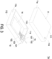
- FIG. 3 is a schematic view illustrating an electric apparatus with an electric connection and protection function according to a second embodiment of the present disclosure.
- FIG. 4A is a schematic perspective view illustrating the first connector of the electric apparatus as shown in FIG. 3 .
- FIG. 4B is a schematic exploded view illustrating the first connector as shown in FIG. 4A and taken along another viewpoint.
- the electric apparatus 1a comprises a casing 11, a first connector 12, a second connector 13 and an electronic component 14.
- the structures of the casing 11, the second connector 13 and the electronic component 14 of the electric apparatus 1a are similar to those of the electric apparatus 1 of the first embodiment, and are not redundantly described herein. Component parts and elements corresponding to those of the first embodiment are designated by identical numeral references, and detailed descriptions thereof are omitted.
- the first connection body 121 and the protection device of the first connector 12 are distinguished.
- the first connection body 121 of the first connector 12 comprises a pin fixture 124 and an inner partition structure 121d.
- the pin fixture 124 is accommodated within the second end 121b of the first connection body 121 in order to support the at least one first pin.
- the inner partition structure 121d is disposed within the first connection body 121.
- the inner partition structure 121d comprises a plurality of through holes 121e. The first pins on the pin fixture 124 are penetrated through the corresponding through holes 121e and extended to the first end 121a of the first connection body 121. Consequently, the junction between the at least one first wire 122 and the corresponding first pin is disposed within the first connection body 121.
- the protection device 123 comprises a protective stopper 125, a potting wall 126 and a protective cap 127.
- the protective stopper 125 comprises at least one third opening 125a.
- the at least one first wire 122 is penetrated through the corresponding third opening 125a.
- the protective stopper 125 is fixed in the first end 121a of the first connection body 121.
- the protective stopper 125 is made of an insulating material.
- the potting wall 126 is connected with and externally protruded from the first end 121a of the first connection body 121. Consequently, the first end 121a of the first connection body 121 is enclosed by the potting wall 126.
- the potting wall 126 is integrally formed with the first end 121a of the first connection body 121.
- the potting wall 126 is made of the insulating material.
- the protective cap 127 comprises at least one fourth opening 127a.
- the at least one first wire 122 is penetrated through the corresponding fourth opening 127a.
- the protective cap 127 is coupled with the potting wall 126. Consequently, the protective stopper 125 is tightly fixed within the potting wall 126.
- the protective cap 127 is made of an insulating material.
- the first connection body 121 further comprises a first engaging element 128, and the protective cap 127 comprises a second engaging element 129.
- the first engaging element 128 and the second engaging element 129 are engaged with each other. Consequently, the protective cap 127 is fixed on the first connection body 121.
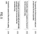
- FIG. 5 is a flowchart illustrating a method of fabricating the first connector of the electric apparatus as shown in FIG. 1 . Please refer to FIGS. 2A to 2D and FIG. 5 .
- a step S11 the assembly of the first connection body 121 and the at least one first wire 122 is provided.
- the connecting relationship between the first connection body 121 and the at least one first wire 122 is identical to that of FIG. 2A , and is not redundantly described herein.
- a protective stopper 123a is provided in a step S12.
- the protective stopper 123a is located at the first end 121a of the first connection body 121.
- the wire-outlet hole 121c and a portion of the first wire 122 close to the first end 121a of the first connection body 121 are covered by the protective stopper 123a.
- a potting wall 123b is connected with and externally protruded from the first end 121a of the first connection body 121. Consequently, the protective stopper 123a is enclosed by the potting wall 123b.
- a protective sealant 123c is filled within the potting wall 123b. Meanwhile, the first connector 121 is fabricated.
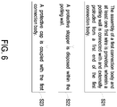
- FIG. 6 is a flowchart illustrating a method of fabricating the first connector of the electric apparatus as shown in FIG. 3 according to an embodiment of the present disclosure. Please refer to FIGS. 4A , 4B and 6 .
- a step S21 the assembly of the first connection body 121 and the at least one first wire 122 is provided.
- the connecting relationship between the first connection body 121 and the at least one first wire 122 is identical to that mentioned above, and is not redundantly described herein.
- a potting wall 126 is connected with and externally protruded from the first end 121a of the first connection body 121.
- a protective stopper 125 is disposed within the potting wall 126 and the at least one first wire 122 is penetrated through the corresponding third opening 125a of the protective stopper 125.
- the wire-outlet hole 121c and a portion of the first wire 122 close to the first end 121a of the first connection body 121 are covered by the protective stopper 125.
- a protective cap 127 is coupled with the first connection body 121. Consequently, the protective stopper 125 is tightly fixed within the potting wall 126. Meanwhile, the first connector 121 is fabricated.
- FIG. 7 is a flowchart illustrating a method of fabricating the first connector of the electric apparatus as shown in FIG. 3 according to another embodiment of the present disclosure.
- the fabricating method further comprises a step S20 before the step S21.
- a pin fixture 124 is disposed within the second end 121b of the first connection body 121.
- the protective stopper 125 is attached to one end of the pin fixture 124.
- the present disclosure provides an electric apparatus with an electric connection and protection function and a connector of the electric apparatus.
- the electric apparatus comprises a wall-mount connector.
- the vacant spaces between the wire-outlet holes of the connector and the wires are sealed. Since the inside and outside of the connector are isolated, the waterproof, temperature-resistant and heat-insulation functions can be achieved. Since the junction between the internal pins of the connector and the wires is not suffered from a rusting problem or a short-circuited problem caused by the ambient moisture, the connecting condition and the operating condition of the electric apparatus are more stable. In such way, the electric apparatus can be applied to the specific environment such as an outdoor low-temperature environment or a high humidity environment.
- the present disclosure provides a method of fabricating the connector in the cost-effective, simplified and mass-production manners.
Abstract
Description
- The present disclosure relates to an electric apparatus, a connector of the electric apparatus and a fabricating method of the connector, and more particularly to an electric apparatus with an electric connection and protection function, a connector of the electric apparatus and a fabricating method of the connector.
- Nowadays, the assembled structure of an insertion element and a docking element is widely used for transferring electric power or signals between an electric apparatus and an electronic system. For example, the electric apparatus comprises an insertion element and a docking element. The insertion element is located at a lateral side of the electric apparatus. The docking element is electrically connected with the electronic system. The wires of the insertion element are outputted from a wire-outlet end thereof. Moreover, the wires are electrically connected with an electronic component within the casing of the electric apparatus. Since the insertion element has wire-outlet holes and there are vacant spaces between the wires and the inner walls of the wire-outlet holes, some drawbacks occur. When the electric apparatus is applied to a specific environment such as an outdoor low-temperature environment or a high humidity environment, the operation of the electric apparatus may result in moisture because of the high temperature of the electric apparatus and the low temperature of the environment. If the moisture enters the insertion element through the vacant spaces between the wire-outlet ends and the wires, the junction between the internal pins of the insertion element and the wires is readily suffered from a rusting problem or a short-circuited problem. Since the connecting condition and the operating condition are not stable, the conventional electric apparatus is easily damaged.
- The present disclosure provides an electric apparatus with an electric connection and protection function and a connector of the electric apparatus. The electric apparatus comprises a wall-mount connector. The vacant spaces between the wire-outlet holes of the connector and the wires are sealed. Since the inside and outside of the wall-mount connector are isolated, the waterproof, temperature-resistant and heat-insulation functions can be achieved. Since the junction between the internal pins of the insertion element and the wires is not suffered from a rusting problem or a short-circuited problem, the connecting condition and the operating condition of the electric apparatus are more stable. In such way, the electric apparatus can be applied to the specific environment such as an outdoor low-temperature environment or a high humidity environment.
- The present disclosure provides a method of fabricating the connector in the cost-effective, simplified and mass-production manners.
- In accordance with an aspect of the present disclosure, an electric apparatus with an electric connection and protection function is provided. The electric apparatus includes a casing, a first connector and at least one electronic component. The casing includes at least one first opening. The first connector is partially embedded in the first opening and fixed on the casing. The first connector includes a first connection body, at least one first wire, a protection device and at least one first pin. The first connection body has a first end and a second end. The at least one first pin is disposed within the first connection body. A first end of the first wire is connected with the corresponding first pin and the first wire is routed from the first end of the first connection body. The protection device is disposed on the first end of the first connection body. The first end of the first connection body and a portion of the at least one first wire are sealed and covered by the protection device. The at least one electronic component is disposed within the casing and electrically connected with a second end of the at least one first wire.
- In accordance with another aspect of the present disclosure, a connector is provided. The connector includes a connection body, at least one pin, at least one wire and a protection device. The connection body has a first end and a second end. The at least one pin is disposed within the connection body. A first end of the wire is connected with the corresponding pin and the wire is routed from the first end of the connection body. The protection device is disposed on the first end of the connection body. The first end of the connection body and a portion of the at least one wire are sealed and covered by the protection device.
- In accordance with another aspect of the present disclosure, a method of fabricating a connector is provided. Firstly, an assembly of a connection body and at least one wire is provided. The connection body has a first end and a second end, and the at least one wire is routed from the first end of the connection body. Then, a protective stopper is formed on the first end of the connection body. Then, a potting wall is formed on the first end of the connection body. The potting wall is connected with and protruded externally from the first end of the connection body to enclose the first end of the connection body, so that the protective stopper is disposed within the potting wall. Then, a protective sealant is filled within the potting wall.
- In accordance with another aspect of the present disclosure, a method of fabricating a connector is provided. Firstly, an assembly of a connection body and at least one wire is provided. The connection body includes a first end and a second end, and the at least one wire is routed from the first end of the connection body. Then, a potting wall is formed on the first end of the connection body. Then, a protective stopper is disposed within the potting wall. Then, a protective cap is coupled with the connection body.
- The above contents of the present disclosure will become more readily apparent to those ordinarily skilled in the art after reviewing the following detailed description and accompanying drawings, in which:
-
-
FIG. 1 is a schematic view illustrating an electric apparatus with an electric connection and protection function according to a first embodiment of the present disclosure; -
FIGS. 2A to 2D schematically illustrate a process of fabricating a first connector of the electric apparatus as shown inFIG. 1 ; -
FIG. 3 is a schematic view illustrating an electric apparatus with an electric connection and protection function according to a second embodiment of the present disclosure; -
FIG. 4A is a schematic perspective view illustrating the first connector of the electric apparatus as shown inFIG. 3 ; -
FIG. 4B is a schematic exploded view illustrating the first connector as shown inFIG. 4A and taken along another viewpoint; -
FIG. 5 is a flowchart illustrating a method of fabricating the first connector of the electric apparatus as shown inFIG. 1 ; -
FIG. 6 is a flowchart illustrating a method of fabricating the first connector of the electric apparatus as shown inFIG. 3 ; and -
FIG. 7 is a flowchart illustrating a method of fabricating the first connector of the electric apparatus as shown inFIG. 3 according to another embodiment of the present disclosure. - The present disclosure will now be described more specifically with reference to the following embodiments. It is to be noted that the following descriptions of preferred embodiments of this disclosure are presented herein for purpose of illustration and description only. It is not intended to be exhaustive or to be limited to the precise form disclosed.
-
FIG. 1 is a schematic view illustrating an electric apparatus with an electric connection and protection function according to a first embodiment of the present disclosure.FIGS. 2A to 2D schematically illustrate a process of fabricating a first connector of the electric apparatus as shown inFIG. 1 . The electric apparatus with an electric connection and protection function 1 (hereinafter referred to as electric apparatus 1) is electrically connected with an electronic system (not shown). Theelectric apparatus 1 comprises acasing 11, afirst connector 12 and anelectronic component 14. - The
casing 11 comprises atop wall 111, abottom wall 112, a plurality oflateral walls 113 and at least onefirst opening 114. Thefirst opening 114 is located at anylateral wall 113, thetop wall 111 or thebottom wall 112. Preferably but not exclusively, thefirst opening 114 is located at thelateral wall 113. In some embodiments, thecasing 11 further comprises aventilation valve 11d. Theventilation valve 11d allows the air in the interior of thecasing 11 to flow therethrough and preventing the moisture in the environment from introducing into the interior of thecasing 11. In this embodiment, thecasing 11 is an assembly of atop cover 11a and abottom cover 11b. Moreover, thecasing 11 further comprises a sealing interface (not shown). Preferably but not exclusively, the sealing interface is located at the junction between thetop cover 11a and thebottom cover 11b. Alternatively, thecasing 11 is assembled through an installation element with another structure. The installation element is formed as thecasing 11 through the sealing interface. In some embodiments, thecasing 11 is a fully-sealed casing. - In this embodiment, the
first connector 12 is a wall-mount connector. Thefirst connector 12 is penetrated through thefirst opening 114 of thecasing 11 and fixed on thecasing 11. Thefirst connector 12 comprises afirst connection body 121, at least onefirst wire 122, aprotection device 123 and a plurality of first pins (not shown). In accordance with the present disclosure, the structure of thefirst connector 12 is specially designed. Hereinafter, the structure of thefirst connector 12 and a method of fabricating thefirst connector 12 will be described with reference toFIGS. 2A to 2D . - Please refer to
FIGS. 1 and2A . Firstly, the main part of thefirst connector 12 is formed. The main part of thefirst connector 12 comprises thefirst connection body 121, the at least onefirst wire 122 and the plurality of first pins (not shown). Thefirst connection body 121 has afirst end 121a and asecond end 121b. When thefirst connection body 121 is penetrated through thefirst opening 114 of thecasing 11, thefirst end 121a of thefirst connection body 121 is disposed within thecasing 11, thesecond end 121b of thefirst connection body 121 is located outside thecasing 11, and a portion of thefirst connection body 121 is embedded within thefirst opening 114 of thecasing 11. Thefirst end 121a of thefirst connection body 121 is served as a wire-outlet end. Moreover, at least one wire-outlet hole 121c is located at thefirst end 121a of thefirst connection body 121. The plurality of first pins are disposed within thefirst connection body 121. Preferably, the at least onefirst wire 122 comprises a plurality of first wires. A first end of thefirst wire 122 is connected with the corresponding first pin. Moreover, the junction between thefirst wire 122 and the corresponding first pin is disposed within thefirst connection body 121. Thefirst wire 122 is routed from the corresponding wire-outlet hole 121c at thefirst end 121a of the first connection body 121 (i.e., the wire-outlet end). A second end of thefirst wire 122 is electrically connected with theelectronic component 14. In an embodiment, theelectronic component 14 is disposed within thecasing 11. Moreover, theelectronic component 14 is connected with the second end of thefirst wire 122. An example of theelectronic component 14 includes but is not limited to a circuit board. - After the main part of the
first connector 12 is formed, theprotection device 123 is provided and coupled to the main part of thefirst connector 12. Please refer toFIGS. 2B ,2C and 2D . Theprotection device 123 is disposed on thefirst end 121a of the first connection body 121 (i.e., the wire-outlet end). Moreover, the wire-outlet hole 121c and a portion of thefirst wire 122 close to thefirst end 121a of thefirst connection body 121 are covered by theprotection device 123. After the vacant space between the wire-outlet hole 121c and thefirst wire 122 is sealed by theprotection device 123, the inside and outside of thefirst connector 12 is isolated from each other and the junction between thefirst cable 122 and thefirst wire 122 can be further isolated from the outside. In an embodiment, theprotection device 123 comprises aprotective stopper 123a, apotting wall 123b and aprotective sealant 123c. - Please refer to
FIG. 2B again. Theprotective stopper 123a is located at thefirst end 121a of thefirst connection body 121. A first side of theprotective stopper 123a is arranged beside thefirst end 121a of thefirst connection body 121, so that the at least one wire-outlet hole 121c is sealed by theprotective stopper 123a. Theprotective stopper 123a comprises at least onesecond opening 123e. The at least onefirst wire 122 is penetrated through the correspondingsecond opening 123e. The wire-outlet hole 121c and a portion of thefirst wire 122 close to thefirst end 121a of thefirst connection body 121 are covered by theprotective stopper 123a. Theprotective stopper 123a is made of an insulating material. - Please refer to
FIG. 2C again. Then, thepotting wall 123b is connected with and externally protruded from thefirst end 121a of thefirst connection body 121. Consequently, theprotective stopper 123a is enclosed by thepotting wall 123b. In addition, a portion of thefirst wire 122 is enclosed by thepotting wall 123b. Consequently, avacant space 123d is formed between the pottingwall 123b and thefirst wire 122. Thevacant space 123d is located beside theprotective stopper 123a. Moreover, thepotting wall 123b is made of the insulating material. - Please refer to
FIG. 2D again. Theprotective sealant 123c is filled in thevacant space 123d within thepotting wall 123b and located beside a second side of theprotective stopper 123a, wherein the second side is opposite to the first side. Moreover, theprotective stopper 123a is made of the insulating material. - As mentioned above, the
protection device 123 is disposed on thefirst end 121a of thefirst connection body 121. Due to theprotection device 123, the air within thefirst connection body 121 of thefirst connector 12 is not communication with the ambient air. Moreover, because of theprotection device 123, no vacant space is formed between thefirst connection body 121 and thefirst wire 122 and the junction between thefirst connection body 121 and thefirst wire 122 is completely sealed. Since theelectric apparatus 1 is not influenced by the ambient moisture, the connecting condition and the operating condition of theelectric apparatus 1 are more stable. - In an embodiment, as shown in
FIG. 1 , theelectric apparatus 1 further comprises asecond connector 13. Thesecond connector 13 comprises asecond connection body 131, at least onesecond wire 132 and at least one second pin (not shown). The at least one second pin is disposed within thesecond connection body 131. A first end of thesecond wire 132 is connected with the corresponding second pin. A second end of thesecond wire 132 is connected with the electronic system (not shown). Thesecond connector 13 is connected with the electronic system to receive electric power or signals from the electronic system or transmit electric power or signals to the electronic system. Thesecond connector 13 is coupled with thefirst connector 12. That is, thesecond connector 13 is coupled with thesecond end 121b of thefirst connection body 121 of thefirst connector 12. Consequently, the at least first pin of thefirst connector 12 and the corresponding second pin of thesecond connector 13 are electrically connected with each other. In such way, electric power or signal can be transferred between the electronic system and theelectric apparatus 1 through thefirst connector 12 and thesecond connector 13. Preferably but not exclusively, thefirst connector 12 and thesecond connector 13 are power connectors (e.g., high voltage power connectors) or signal connectors. In case that thefirst connector 12 is a female connector, thesecond connector 13 is a male connector. In case that thefirst connector 12 is a male connector, thesecond connector 13 is a female connector. -
FIG. 3 is a schematic view illustrating an electric apparatus with an electric connection and protection function according to a second embodiment of the present disclosure.FIG. 4A is a schematic perspective view illustrating the first connector of the electric apparatus as shown inFIG. 3 .FIG. 4B is a schematic exploded view illustrating the first connector as shown inFIG. 4A and taken along another viewpoint. Theelectric apparatus 1a comprises acasing 11, afirst connector 12, asecond connector 13 and anelectronic component 14. The structures of thecasing 11, thesecond connector 13 and theelectronic component 14 of theelectric apparatus 1a are similar to those of theelectric apparatus 1 of the first embodiment, and are not redundantly described herein. Component parts and elements corresponding to those of the first embodiment are designated by identical numeral references, and detailed descriptions thereof are omitted. In comparison with the first embodiment, thefirst connection body 121 and the protection device of thefirst connector 12 are distinguished. - In this embodiment, the
first connection body 121 of thefirst connector 12 comprises apin fixture 124 and aninner partition structure 121d. Thepin fixture 124 is accommodated within thesecond end 121b of thefirst connection body 121 in order to support the at least one first pin. Theinner partition structure 121d is disposed within thefirst connection body 121. Theinner partition structure 121d comprises a plurality of throughholes 121e. The first pins on thepin fixture 124 are penetrated through the corresponding throughholes 121e and extended to thefirst end 121a of thefirst connection body 121. Consequently, the junction between the at least onefirst wire 122 and the corresponding first pin is disposed within thefirst connection body 121. - In this embodiment, the
protection device 123 comprises aprotective stopper 125, apotting wall 126 and aprotective cap 127. - The
protective stopper 125 comprises at least onethird opening 125a. The at least onefirst wire 122 is penetrated through the correspondingthird opening 125a. Moreover, theprotective stopper 125 is fixed in thefirst end 121a of thefirst connection body 121. Theprotective stopper 125 is made of an insulating material. - The
potting wall 126 is connected with and externally protruded from thefirst end 121a of thefirst connection body 121. Consequently, thefirst end 121a of thefirst connection body 121 is enclosed by thepotting wall 126. Preferably, thepotting wall 126 is integrally formed with thefirst end 121a of thefirst connection body 121. Moreover, thepotting wall 126 is made of the insulating material. - The
protective cap 127 comprises at least onefourth opening 127a. The at least onefirst wire 122 is penetrated through the correspondingfourth opening 127a. Moreover, theprotective cap 127 is coupled with thepotting wall 126. Consequently, theprotective stopper 125 is tightly fixed within thepotting wall 126. Theprotective cap 127 is made of an insulating material. - In an embodiment, the
first connection body 121 further comprises a firstengaging element 128, and theprotective cap 127 comprises a secondengaging element 129. The firstengaging element 128 and the secondengaging element 129 are engaged with each other. Consequently, theprotective cap 127 is fixed on thefirst connection body 121. -
FIG. 5 is a flowchart illustrating a method of fabricating the first connector of the electric apparatus as shown inFIG. 1 . Please refer toFIGS. 2A to 2D andFIG. 5 . Firstly, in a step S11, the assembly of thefirst connection body 121 and the at least onefirst wire 122 is provided. The connecting relationship between thefirst connection body 121 and the at least onefirst wire 122 is identical to that ofFIG. 2A , and is not redundantly described herein. In a step S12, aprotective stopper 123a is provided. Theprotective stopper 123a is located at thefirst end 121a of thefirst connection body 121. The wire-outlet hole 121c and a portion of thefirst wire 122 close to thefirst end 121a of thefirst connection body 121 are covered by theprotective stopper 123a. In a step S13, apotting wall 123b is connected with and externally protruded from thefirst end 121a of thefirst connection body 121. Consequently, theprotective stopper 123a is enclosed by thepotting wall 123b. In a step S14, aprotective sealant 123c is filled within thepotting wall 123b. Meanwhile, thefirst connector 121 is fabricated. -
FIG. 6 is a flowchart illustrating a method of fabricating the first connector of the electric apparatus as shown inFIG. 3 according to an embodiment of the present disclosure. Please refer toFIGS. 4A ,4B and6 . Firstly, in a step S21, the assembly of thefirst connection body 121 and the at least onefirst wire 122 is provided. The connecting relationship between thefirst connection body 121 and the at least onefirst wire 122 is identical to that mentioned above, and is not redundantly described herein. Moreover, apotting wall 126 is connected with and externally protruded from thefirst end 121a of thefirst connection body 121. In a step S22, aprotective stopper 125 is disposed within thepotting wall 126 and the at least onefirst wire 122 is penetrated through the correspondingthird opening 125a of theprotective stopper 125. The wire-outlet hole 121c and a portion of thefirst wire 122 close to thefirst end 121a of thefirst connection body 121 are covered by theprotective stopper 125. In a step S23, aprotective cap 127 is coupled with thefirst connection body 121. Consequently, theprotective stopper 125 is tightly fixed within thepotting wall 126. Meanwhile, thefirst connector 121 is fabricated. -
FIG. 7 is a flowchart illustrating a method of fabricating the first connector of the electric apparatus as shown inFIG. 3 according to another embodiment of the present disclosure. In comparison with the embodiment ofFIG. 6 , the fabricating method further comprises a step S20 before the step S21. In the step S20, apin fixture 124 is disposed within thesecond end 121b of thefirst connection body 121. In some embodiments, in the step S22, theprotective stopper 125 is attached to one end of thepin fixture 124. - From the above descriptions, the present disclosure provides an electric apparatus with an electric connection and protection function and a connector of the electric apparatus. The electric apparatus comprises a wall-mount connector. The vacant spaces between the wire-outlet holes of the connector and the wires are sealed. Since the inside and outside of the connector are isolated, the waterproof, temperature-resistant and heat-insulation functions can be achieved. Since the junction between the internal pins of the connector and the wires is not suffered from a rusting problem or a short-circuited problem caused by the ambient moisture, the connecting condition and the operating condition of the electric apparatus are more stable. In such way, the electric apparatus can be applied to the specific environment such as an outdoor low-temperature environment or a high humidity environment. The present disclosure provides a method of fabricating the connector in the cost-effective, simplified and mass-production manners.
Claims (15)
- An electric apparatus (1, 1a) with an electric connection and protection function, characterized in that the electric apparatus (1, 1a) comprises:a casing (11) comprising at least one first opening (114);a first connector (12) partially embedded in the first opening (114) and fixed on the casing (11), wherein the first connector (12) comprises a first connection body (121), at least one first wire (122), a protection device (123) and at least one first pin, wherein the first connection body (121) has a first end (121a) and a second end (121b), the at least one first pin is disposed within the first connection body (121), a first end of the first wire (122) is connected with the corresponding first pin and the first wire (122) is routed from the first end (121a) of the first connection body (121), the protection device (123) is disposed on the first end (121a) of the first connection body (121), and the first end (121a) of the first connection body (121) and a portion of the at least one first wire (122) are sealed and covered by the protection device (123); andat least one electronic component (14) disposed within the casing (11) and electrically connected with a second end of the at least one first wire (122).
- The electric apparatus (1, 1a) according to claim 1, wherein the first connector (12) is a wall-mount connector, and the first connector (12) is penetrated through the first opening (114) of the casing (11) and fixed on the casing (11).
- The electric apparatus (1, 1a) according to claim 1, wherein the first end (121a) of the first connection body (121) is disposed within the casing (11), the second end (121b) of the first connection body (121) is located outside the casing (11), and a portion of the first connection body (121) is embedded within the first opening (114) of the casing (11).
- The electric apparatus (1, 1a) according to claim 1, wherein the first connection body (121) comprises at least one wire-outlet hole (121c) located at the first end (121a) thereof, a junction between the first wire (122) and the corresponding first pin is disposed within the first connection body (121), and the at least one first wire (122) is routed from the corresponding wire-outlet hole (121c).
- The electric apparatus (1, 1a) according to claim 4, wherein the at least one wire-outlet hole (121c) and a portion of the at least one first wire (122) close to the first end (121a) of the first connection body (121) are covered and sealed by the protection device (123), so that a vacant space formed between the at least one wire-outlet hole (121c) and the corresponding first wire (122) is sealed.
- The electric apparatus (1, 1a) according to claim 5, wherein the protection device (123) comprises:a protective stopper (123a) located at the first end (121a) of the first connection body (121), wherein a first side of the protective stopper (123a) is arranged beside the first end (121a) of the first connection body (121), so that the at least one wire-outlet hole (121c) is sealed by the protective stopper (123a), wherein the protective stopper (123a) comprises at least one second opening (123e), and the at least one first wire (122) is penetrated through the corresponding second opening (123e);a potting wall (123b) connected with and protruded externally from the first end (121a) of the first connection body (121) to enclose the first end (121a) of the first connection body (121), wherein the protective stopper (123a) is disposed within the potting wall (123b); anda protective sealant (123c) filled within the potting wall (123b), and arranged beside a second side of the protective stopper (123a), wherein the second side is opposite to the first side.
- The electric apparatus (1, 1a) according to claim 5, wherein the protection device (123) comprises:a protective stopper (125) located at the first end (121a) of the first connection body (121), wherein a first side of the protective stopper (125) is arranged beside the first end (121a) of the first connection body (121), so that the at least one wire-outlet hole (121c) is sealed by the protective stopper (125), wherein the protective stopper (125) comprises at least one third opening (125a), and the at least one first wire (122) is penetrated through the corresponding third opening (125a);a potting wall (126) connected with and protruded externally from the first end (121a) of the first connection body (121) to enclose the first end (121a) of the first connection body (121), wherein the protective stopper (125) is disposed within the potting wall (126); anda protective cap (127) coupled with the first connection body (121), wherein at least a portion of the protective cap (127) is accommodated within the potting wall (126), so that the protective stopper (125) is fixed within the potting wall (126).
- The electric apparatus (1, 1a) according to claim 7, wherein the first connection body (121) further comprises a first engaging element (128), and the protective cap (127) comprises a second engaging element (129), wherein the first engaging element (128) and the second engaging element (129) are engaged with each other, so that the protective cap (127) is fixed on the first connection body (121).
- The electric apparatus (1, 1a) according to claim 1, wherein the electric apparatus (1, 1a) further comprises a second connector (13), and the second connector (13) is coupled with the first connector (11), wherein the second connector (13) comprises a second connection body (131), at least one second wire (132) and at least one second pin, wherein the at least one second pin is disposed within the second connection body (131), a first end of the at least one second wire (132) is connected with the corresponding second pin, and a second end of the at least one second wire (132) is connected with an electronic system.
- A connector (12), characterized in that the connector comprises:a connection body (121) having a first end (121a) and a second end (121b);at least one pin disposed within the connection body (121);at least one wire (122), wherein a first end of the wire (122) is connected with the corresponding pin and routed from the first end (121a) of the connection body (121); anda protection device (123) disposed on the first end (121a) of the connection body (121), wherein the first end (121a) of the connection body (121) and a portion of the at least one wire (122) are sealed and covered by the protection device (123).
- The connector (12) according to claim 10, wherein the connector (12) is a wall-mount connector, and the connector (12) is partially embedded in an opening (114) of a casing (11), wherein the first end (121a) of the connection body (121) is disposed within the casing (11), the second end (121b) of the connection body (121) is located outside the casing (11), and a portion of the connection body (121) is embedded within the opening (114) of the casing (11).
- The connector (12) according to claim 10, wherein the connection body (121) comprises at least one wire-outlet hole (121c) located at the first end (121a) thereof, a junction between the wire (122) and the corresponding pin is disposed within the connection body (121), and the at least one wire (122) is routed from the corresponding wire-outlet hole (121c); the at least one wire-outlet hole (121c) and a portion of the at least one wire (122) close to the first end (121a) of the connection body (121) are covered and sealed by the protection device (123), so that a vacant space formed between the at least one wire-outlet hole (121c) and the corresponding wire (122) is sealed.
- The connector (12) according to claim 12, wherein the protection device (123) comprises:a protective stopper (123a) located at the first end (121a) of the connection body (121), wherein a first side of the protective stopper (123a) is arranged beside the first end (121a) of the first connection body (121), so that the at least one wire-outlet hole (121c) is sealed by the protective stopper (123a), wherein the protective stopper (123a) comprises an opening (123e), and the at least one wire (122) is penetrated through the corresponding opening (123e) of the protective stopper (123a);a potting wall (123b) connected with and protruded externally from the first end (121a) of the connection body (121) to enclose the first end (121a) of the connection body (121), wherein the protective stopper (123a) is disposed within the potting wall (123b); anda protective sealant (123c) filled within the potting wall (123b), and arranged beside a second side of the protective stopper (123a).
- The connector (12) according to claim 12, wherein the protection device (123) comprises:a protective stopper (125) located at the first end (121a) of the connection body (121), wherein a first side of the protective stopper (125) is arranged beside the first end (121a) of the first connection body (121), so that the at least one wire-outlet hole (121c) is sealed by the protective stopper (125), wherein the protective stopper (125) comprises at least one opening (125a), and the at least one wire (122) is penetrated through the corresponding opening (125a) of the protective stopper (125);a potting wall (126) connected with and protruded externally from the first end (121a) of the connection body (121) to enclose the first end (121a) of the connection body (121), wherein the protective stopper (125) is disposed within the potting wall (126); anda protective cap (127) coupled with the connection body (121), wherein at least a portion of the protective cap (127) is accommodated within the potting wall (126), so that the protective stopper (125) is fixed within the potting wall (126).
- The connector (12) according to claim 14, wherein the connection body (121) further comprises a first engaging element (128), and the protective cap (127) comprises a second engaging element (129), wherein the first engaging element (127) and the second engaging element (129) are engaged with each other, so that the protective cap (127) is fixed on the connection body (121).
Priority Applications (1)
| Application Number | Priority Date | Filing Date | Title |
|---|---|---|---|
| EP23183247.8A EP4239809A3 (en) | 2019-01-09 | 2019-12-11 | Electric apparatus with electric connection and protection function, connector and fabricating method thereof |
Applications Claiming Priority (1)
| Application Number | Priority Date | Filing Date | Title |
|---|---|---|---|
| CN201910019863.6A CN109861031B (en) | 2019-01-09 | 2019-01-09 | Electric appliance device with electric connection protection function, connecting piece and manufacturing method |
Related Child Applications (2)
| Application Number | Title | Priority Date | Filing Date |
|---|---|---|---|
| EP23183247.8A Division EP4239809A3 (en) | 2019-01-09 | 2019-12-11 | Electric apparatus with electric connection and protection function, connector and fabricating method thereof |
| EP23183247.8A Division-Into EP4239809A3 (en) | 2019-01-09 | 2019-12-11 | Electric apparatus with electric connection and protection function, connector and fabricating method thereof |
Publications (2)
| Publication Number | Publication Date |
|---|---|
| EP3680988A1 true EP3680988A1 (en) | 2020-07-15 |
| EP3680988B1 EP3680988B1 (en) | 2023-08-23 |
Family
ID=66894279
Family Applications (2)
| Application Number | Title | Priority Date | Filing Date |
|---|---|---|---|
| EP23183247.8A Pending EP4239809A3 (en) | 2019-01-09 | 2019-12-11 | Electric apparatus with electric connection and protection function, connector and fabricating method thereof |
| EP19215290.8A Active EP3680988B1 (en) | 2019-01-09 | 2019-12-11 | Electric apparatus with electric connection and protection function |
Family Applications Before (1)
| Application Number | Title | Priority Date | Filing Date |
|---|---|---|---|
| EP23183247.8A Pending EP4239809A3 (en) | 2019-01-09 | 2019-12-11 | Electric apparatus with electric connection and protection function, connector and fabricating method thereof |
Country Status (2)
| Country | Link |
|---|---|
| EP (2) | EP4239809A3 (en) |
| CN (1) | CN109861031B (en) |
Citations (6)
| Publication number | Priority date | Publication date | Assignee | Title |
|---|---|---|---|---|
| US4629269A (en) * | 1977-10-25 | 1986-12-16 | Allied Corporation | Electrical connector with environmental seal |
| DE19933829A1 (en) * | 1998-07-23 | 2000-02-10 | Yazaki Corp | Water tight plug with water tight gel through which connection is made, where loose gel is prevented from adhering to connector part |
| EP1024557A1 (en) * | 1999-01-29 | 2000-08-02 | Sumitomo Wiring Systems, Ltd. | A sealing plug for a watertight connector and a watertight connector |
| WO2010050336A1 (en) * | 2008-10-30 | 2010-05-06 | 矢崎総業株式会社 | Waterproof connector |
| EP2525443A1 (en) * | 2011-05-17 | 2012-11-21 | Sumitomo Wiring Systems, Ltd. | Vehicle-side connector and mounting method therefor |
| CN207009780U (en) * | 2017-06-28 | 2018-02-13 | 安徽江淮汽车集团股份有限公司 | A kind of single-end sealed low pressure plug-in unit |
Family Cites Families (10)
| Publication number | Priority date | Publication date | Assignee | Title |
|---|---|---|---|---|
| DE29617238U1 (en) * | 1996-10-04 | 1996-11-21 | Roland Man Druckmasch | Plug connection for an assembly located under a cover |
| JP5035132B2 (en) * | 2008-06-19 | 2012-09-26 | 住友電装株式会社 | Waterproof connector |
| JP2010040436A (en) * | 2008-08-07 | 2010-02-18 | Yazaki Corp | Connector |
| JP2011198499A (en) * | 2010-03-17 | 2011-10-06 | Yazaki Corp | Connector |
| JP2015072797A (en) * | 2013-10-03 | 2015-04-16 | 矢崎総業株式会社 | Connector |
| CN106532300B (en) * | 2016-11-30 | 2019-04-23 | 金湖金诚电子科技有限公司 | A kind of waterproof terminal harness for HDMI high definition connecting line |
| CN106785655B (en) * | 2017-01-19 | 2019-03-08 | 丁青松 | A kind of water-proof connector |
| JP2019009031A (en) * | 2017-06-27 | 2019-01-17 | Smk株式会社 | Waterproof terminal block |
| CN207069250U (en) * | 2017-08-24 | 2018-03-02 | 东莞市南谷第电子有限公司 | A kind of waterproof SR terminal lines of improvement |
| CN207994229U (en) * | 2018-04-12 | 2018-10-19 | 深圳智贝壳科技有限公司 | Easy to use and reliable plug connector module |
-
2019
- 2019-01-09 CN CN201910019863.6A patent/CN109861031B/en active Active
- 2019-12-11 EP EP23183247.8A patent/EP4239809A3/en active Pending
- 2019-12-11 EP EP19215290.8A patent/EP3680988B1/en active Active
Patent Citations (6)
| Publication number | Priority date | Publication date | Assignee | Title |
|---|---|---|---|---|
| US4629269A (en) * | 1977-10-25 | 1986-12-16 | Allied Corporation | Electrical connector with environmental seal |
| DE19933829A1 (en) * | 1998-07-23 | 2000-02-10 | Yazaki Corp | Water tight plug with water tight gel through which connection is made, where loose gel is prevented from adhering to connector part |
| EP1024557A1 (en) * | 1999-01-29 | 2000-08-02 | Sumitomo Wiring Systems, Ltd. | A sealing plug for a watertight connector and a watertight connector |
| WO2010050336A1 (en) * | 2008-10-30 | 2010-05-06 | 矢崎総業株式会社 | Waterproof connector |
| EP2525443A1 (en) * | 2011-05-17 | 2012-11-21 | Sumitomo Wiring Systems, Ltd. | Vehicle-side connector and mounting method therefor |
| CN207009780U (en) * | 2017-06-28 | 2018-02-13 | 安徽江淮汽车集团股份有限公司 | A kind of single-end sealed low pressure plug-in unit |
Also Published As
| Publication number | Publication date |
|---|---|
| EP4239809A2 (en) | 2023-09-06 |
| CN109861031B (en) | 2021-12-17 |
| CN109861031A (en) | 2019-06-07 |
| EP4239809A3 (en) | 2023-10-25 |
| EP3680988B1 (en) | 2023-08-23 |
Similar Documents
| Publication | Publication Date | Title |
|---|---|---|
| US6372993B1 (en) | Sealed terminal assembly for hermetic compressor | |
| JP2831624B2 (en) | Electrical connector plug | |
| US11721940B2 (en) | Coaxial connector with partition | |
| US8272891B2 (en) | Connector | |
| JP2009129811A (en) | Electromagnetic wave shield connector | |
| EP2312701A1 (en) | Shield cover, shield case, and circuit board module | |
| US10651578B2 (en) | Connector and connector assembly | |
| EP1739794B1 (en) | Terminal cluster block | |
| JP4248333B2 (en) | Electrical connection system | |
| US11631954B2 (en) | Coaxial connector for a circuit board | |
| JP5578815B2 (en) | Cable connector | |
| US20180006390A1 (en) | Electrical Connector, Electronic Component, and Assembly Method | |
| US8338708B2 (en) | Electric junction box joint structure | |
| US7347724B2 (en) | Electrical multiple receptacle outlet | |
| EP3680988A1 (en) | Electric apparatus with electric connection and protection function, connector and fabricating method thereof | |
| US9692221B2 (en) | Junction box and contactor device | |
| US11837941B2 (en) | Motor device with integrated connection assembly | |
| US5070314A (en) | Hermetic module containing microwave component | |
| US10320170B2 (en) | Electrical connection structure | |
| CN205385146U (en) | High waterproof performance radio frequency connector | |
| JP2007221909A (en) | Power cable connection and insulation plug thereof | |
| US9325108B2 (en) | Electrical connector assembly for an electronic module | |
| JP7107659B2 (en) | electric junction box | |
| EP2876756A1 (en) | Connector assembly | |
| CN117220065A (en) | Wire connector assembly and main end wire connector thereof |
Legal Events
| Date | Code | Title | Description |
|---|---|---|---|
| PUAI | Public reference made under article 153(3) epc to a published international application that has entered the european phase |
Free format text: ORIGINAL CODE: 0009012 |
|
| STAA | Information on the status of an ep patent application or granted ep patent |
Free format text: STATUS: THE APPLICATION HAS BEEN PUBLISHED |
|
| AK | Designated contracting states |
Kind code of ref document: A1 Designated state(s): AL AT BE BG CH CY CZ DE DK EE ES FI FR GB GR HR HU IE IS IT LI LT LU LV MC MK MT NL NO PL PT RO RS SE SI SK SM TR |
|
| AX | Request for extension of the european patent |
Extension state: BA ME |
|
| STAA | Information on the status of an ep patent application or granted ep patent |
Free format text: STATUS: REQUEST FOR EXAMINATION WAS MADE |
|
| 17P | Request for examination filed |
Effective date: 20210112 |
|
| RBV | Designated contracting states (corrected) |
Designated state(s): AL AT BE BG CH CY CZ DE DK EE ES FI FR GB GR HR HU IE IS IT LI LT LU LV MC MK MT NL NO PL PT RO RS SE SI SK SM TR |
|
| STAA | Information on the status of an ep patent application or granted ep patent |
Free format text: STATUS: EXAMINATION IS IN PROGRESS |
|
| 17Q | First examination report despatched |
Effective date: 20211208 |
|
| GRAP | Despatch of communication of intention to grant a patent |
Free format text: ORIGINAL CODE: EPIDOSNIGR1 |
|
| STAA | Information on the status of an ep patent application or granted ep patent |
Free format text: STATUS: GRANT OF PATENT IS INTENDED |
|
| RIC1 | Information provided on ipc code assigned before grant |
Ipc: H01R 24/60 20110101ALN20230216BHEP Ipc: H01R 13/74 20060101ALN20230216BHEP Ipc: H01R 13/506 20060101ALN20230216BHEP Ipc: H02B 1/00 20060101ALN20230216BHEP Ipc: H05K 5/06 20060101ALI20230216BHEP Ipc: H01R 13/52 20060101AFI20230216BHEP |
|
| RIC1 | Information provided on ipc code assigned before grant |
Ipc: H01R 24/60 20110101ALN20230228BHEP Ipc: H01R 13/74 20060101ALN20230228BHEP Ipc: H01R 13/506 20060101ALN20230228BHEP Ipc: H02B 1/00 20060101ALN20230228BHEP Ipc: H05K 5/06 20060101ALI20230228BHEP Ipc: H01R 13/52 20060101AFI20230228BHEP |
|
| INTG | Intention to grant announced |
Effective date: 20230317 |
|
| GRAS | Grant fee paid |
Free format text: ORIGINAL CODE: EPIDOSNIGR3 |
|
| GRAA | (expected) grant |
Free format text: ORIGINAL CODE: 0009210 |
|
| STAA | Information on the status of an ep patent application or granted ep patent |
Free format text: STATUS: THE PATENT HAS BEEN GRANTED |
|
| P01 | Opt-out of the competence of the unified patent court (upc) registered |
Effective date: 20230712 |
|
| AK | Designated contracting states |
Kind code of ref document: B1 Designated state(s): AL AT BE BG CH CY CZ DE DK EE ES FI FR GB GR HR HU IE IS IT LI LT LU LV MC MK MT NL NO PL PT RO RS SE SI SK SM TR |
|
| REG | Reference to a national code |
Ref country code: GB Ref legal event code: FG4D |
|
| REG | Reference to a national code |
Ref country code: CH Ref legal event code: EP |
|
| REG | Reference to a national code |
Ref country code: IE Ref legal event code: FG4D |
|
| REG | Reference to a national code |
Ref country code: DE Ref legal event code: R096 Ref document number: 602019035511 Country of ref document: DE |
|
| REG | Reference to a national code |
Ref country code: LT Ref legal event code: MG9D |
|
| REG | Reference to a national code |
Ref country code: NL Ref legal event code: MP Effective date: 20230823 |
|
| REG | Reference to a national code |
Ref country code: AT Ref legal event code: MK05 Ref document number: 1603688 Country of ref document: AT Kind code of ref document: T Effective date: 20230823 |
|
| PG25 | Lapsed in a contracting state [announced via postgrant information from national office to epo] |
Ref country code: GR Free format text: LAPSE BECAUSE OF FAILURE TO SUBMIT A TRANSLATION OF THE DESCRIPTION OR TO PAY THE FEE WITHIN THE PRESCRIBED TIME-LIMIT Effective date: 20231124 |
|
| PG25 | Lapsed in a contracting state [announced via postgrant information from national office to epo] |
Ref country code: IS Free format text: LAPSE BECAUSE OF FAILURE TO SUBMIT A TRANSLATION OF THE DESCRIPTION OR TO PAY THE FEE WITHIN THE PRESCRIBED TIME-LIMIT Effective date: 20231223 |
|
| PG25 | Lapsed in a contracting state [announced via postgrant information from national office to epo] |
Ref country code: SE Free format text: LAPSE BECAUSE OF FAILURE TO SUBMIT A TRANSLATION OF THE DESCRIPTION OR TO PAY THE FEE WITHIN THE PRESCRIBED TIME-LIMIT Effective date: 20230823 Ref country code: RS Free format text: LAPSE BECAUSE OF FAILURE TO SUBMIT A TRANSLATION OF THE DESCRIPTION OR TO PAY THE FEE WITHIN THE PRESCRIBED TIME-LIMIT Effective date: 20230823 Ref country code: PT Free format text: LAPSE BECAUSE OF FAILURE TO SUBMIT A TRANSLATION OF THE DESCRIPTION OR TO PAY THE FEE WITHIN THE PRESCRIBED TIME-LIMIT Effective date: 20231226 Ref country code: NO Free format text: LAPSE BECAUSE OF FAILURE TO SUBMIT A TRANSLATION OF THE DESCRIPTION OR TO PAY THE FEE WITHIN THE PRESCRIBED TIME-LIMIT Effective date: 20231123 Ref country code: NL Free format text: LAPSE BECAUSE OF FAILURE TO SUBMIT A TRANSLATION OF THE DESCRIPTION OR TO PAY THE FEE WITHIN THE PRESCRIBED TIME-LIMIT Effective date: 20230823 Ref country code: LV Free format text: LAPSE BECAUSE OF FAILURE TO SUBMIT A TRANSLATION OF THE DESCRIPTION OR TO PAY THE FEE WITHIN THE PRESCRIBED TIME-LIMIT Effective date: 20230823 Ref country code: LT Free format text: LAPSE BECAUSE OF FAILURE TO SUBMIT A TRANSLATION OF THE DESCRIPTION OR TO PAY THE FEE WITHIN THE PRESCRIBED TIME-LIMIT Effective date: 20230823 Ref country code: IS Free format text: LAPSE BECAUSE OF FAILURE TO SUBMIT A TRANSLATION OF THE DESCRIPTION OR TO PAY THE FEE WITHIN THE PRESCRIBED TIME-LIMIT Effective date: 20231223 Ref country code: HR Free format text: LAPSE BECAUSE OF FAILURE TO SUBMIT A TRANSLATION OF THE DESCRIPTION OR TO PAY THE FEE WITHIN THE PRESCRIBED TIME-LIMIT Effective date: 20230823 Ref country code: GR Free format text: LAPSE BECAUSE OF FAILURE TO SUBMIT A TRANSLATION OF THE DESCRIPTION OR TO PAY THE FEE WITHIN THE PRESCRIBED TIME-LIMIT Effective date: 20231124 Ref country code: FI Free format text: LAPSE BECAUSE OF FAILURE TO SUBMIT A TRANSLATION OF THE DESCRIPTION OR TO PAY THE FEE WITHIN THE PRESCRIBED TIME-LIMIT Effective date: 20230823 Ref country code: AT Free format text: LAPSE BECAUSE OF FAILURE TO SUBMIT A TRANSLATION OF THE DESCRIPTION OR TO PAY THE FEE WITHIN THE PRESCRIBED TIME-LIMIT Effective date: 20230823 |
|
| PGFP | Annual fee paid to national office [announced via postgrant information from national office to epo] |
Ref country code: IT Payment date: 20231123 Year of fee payment: 5 Ref country code: FR Payment date: 20231009 Year of fee payment: 5 Ref country code: DE Payment date: 20231017 Year of fee payment: 5 |
|
| PG25 | Lapsed in a contracting state [announced via postgrant information from national office to epo] |
Ref country code: PL Free format text: LAPSE BECAUSE OF FAILURE TO SUBMIT A TRANSLATION OF THE DESCRIPTION OR TO PAY THE FEE WITHIN THE PRESCRIBED TIME-LIMIT Effective date: 20230823 |