EP1587174B1 - A connector and a connector assembly - Google Patents
A connector and a connector assembly Download PDFInfo
- Publication number
- EP1587174B1 EP1587174B1 EP05008000A EP05008000A EP1587174B1 EP 1587174 B1 EP1587174 B1 EP 1587174B1 EP 05008000 A EP05008000 A EP 05008000A EP 05008000 A EP05008000 A EP 05008000A EP 1587174 B1 EP1587174 B1 EP 1587174B1
- Authority
- EP
- European Patent Office
- Prior art keywords
- terminal fittings
- cavities
- retainer
- locking
- connector
- Prior art date
- Legal status (The legal status is an assumption and is not a legal conclusion. Google has not performed a legal analysis and makes no representation as to the accuracy of the status listed.)
- Ceased
Links
- 230000037431 insertion Effects 0.000 claims description 25
- 238000003780 insertion Methods 0.000 claims description 25
- 230000013011 mating Effects 0.000 claims description 14
- 238000006073 displacement reaction Methods 0.000 description 6
- 230000036544 posture Effects 0.000 description 4
- 238000007789 sealing Methods 0.000 description 4
- 210000000078 claw Anatomy 0.000 description 3
- 238000010276 construction Methods 0.000 description 3
- 238000009413 insulation Methods 0.000 description 3
- 239000000463 material Substances 0.000 description 3
- 230000000717 retained effect Effects 0.000 description 3
- 229920003002 synthetic resin Polymers 0.000 description 3
- 239000000057 synthetic resin Substances 0.000 description 3
- 238000000576 coating method Methods 0.000 description 2
- 238000005452 bending Methods 0.000 description 1
- 239000004020 conductor Substances 0.000 description 1
- 230000001419 dependent effect Effects 0.000 description 1
- 230000000694 effects Effects 0.000 description 1
- 239000002184 metal Substances 0.000 description 1
- 230000002093 peripheral effect Effects 0.000 description 1
Images


Classifications
-
- F—MECHANICAL ENGINEERING; LIGHTING; HEATING; WEAPONS; BLASTING
- F24—HEATING; RANGES; VENTILATING
- F24F—AIR-CONDITIONING; AIR-HUMIDIFICATION; VENTILATION; USE OF AIR CURRENTS FOR SCREENING
- F24F13/00—Details common to, or for air-conditioning, air-humidification, ventilation or use of air currents for screening
- F24F13/02—Ducting arrangements
- F24F13/06—Outlets for directing or distributing air into rooms or spaces, e.g. ceiling air diffuser
- F24F13/068—Outlets for directing or distributing air into rooms or spaces, e.g. ceiling air diffuser formed as perforated walls, ceilings or floors
-
- H—ELECTRICITY
- H01—ELECTRIC ELEMENTS
- H01R—ELECTRICALLY-CONDUCTIVE CONNECTIONS; STRUCTURAL ASSOCIATIONS OF A PLURALITY OF MUTUALLY-INSULATED ELECTRICAL CONNECTING ELEMENTS; COUPLING DEVICES; CURRENT COLLECTORS
- H01R13/00—Details of coupling devices of the kinds covered by groups H01R12/70 or H01R24/00 - H01R33/00
- H01R13/40—Securing contact members in or to a base or case; Insulating of contact members
- H01R13/42—Securing in a demountable manner
- H01R13/436—Securing a plurality of contact members by one locking piece or operation
- H01R13/4361—Insertion of locking piece perpendicular to direction of contact insertion
- H01R13/4362—Insertion of locking piece perpendicular to direction of contact insertion comprising a temporary and a final locking position
-
- F—MECHANICAL ENGINEERING; LIGHTING; HEATING; WEAPONS; BLASTING
- F24—HEATING; RANGES; VENTILATING
- F24F—AIR-CONDITIONING; AIR-HUMIDIFICATION; VENTILATION; USE OF AIR CURRENTS FOR SCREENING
- F24F13/00—Details common to, or for air-conditioning, air-humidification, ventilation or use of air currents for screening
- F24F13/08—Air-flow control members, e.g. louvres, grilles, flaps or guide plates
- F24F13/10—Air-flow control members, e.g. louvres, grilles, flaps or guide plates movable, e.g. dampers
-
- F—MECHANICAL ENGINEERING; LIGHTING; HEATING; WEAPONS; BLASTING
- F24—HEATING; RANGES; VENTILATING
- F24F—AIR-CONDITIONING; AIR-HUMIDIFICATION; VENTILATION; USE OF AIR CURRENTS FOR SCREENING
- F24F2221/00—Details or features not otherwise provided for
- F24F2221/14—Details or features not otherwise provided for mounted on the ceiling
-
- F—MECHANICAL ENGINEERING; LIGHTING; HEATING; WEAPONS; BLASTING
- F24—HEATING; RANGES; VENTILATING
- F24F—AIR-CONDITIONING; AIR-HUMIDIFICATION; VENTILATION; USE OF AIR CURRENTS FOR SCREENING
- F24F2221/00—Details or features not otherwise provided for
- F24F2221/17—Details or features not otherwise provided for mounted in a wall
-
- H—ELECTRICITY
- H01—ELECTRIC ELEMENTS
- H01R—ELECTRICALLY-CONDUCTIVE CONNECTIONS; STRUCTURAL ASSOCIATIONS OF A PLURALITY OF MUTUALLY-INSULATED ELECTRICAL CONNECTING ELEMENTS; COUPLING DEVICES; CURRENT COLLECTORS
- H01R13/00—Details of coupling devices of the kinds covered by groups H01R12/70 or H01R24/00 - H01R33/00
- H01R13/40—Securing contact members in or to a base or case; Insulating of contact members
- H01R13/42—Securing in a demountable manner
- H01R13/422—Securing in resilient one-piece base or case, e.g. by friction; One-piece base or case formed with resilient locking means
- H01R13/4223—Securing in resilient one-piece base or case, e.g. by friction; One-piece base or case formed with resilient locking means comprising integral flexible contact retaining fingers
-
- H—ELECTRICITY
- H01—ELECTRIC ELEMENTS
- H01R—ELECTRICALLY-CONDUCTIVE CONNECTIONS; STRUCTURAL ASSOCIATIONS OF A PLURALITY OF MUTUALLY-INSULATED ELECTRICAL CONNECTING ELEMENTS; COUPLING DEVICES; CURRENT COLLECTORS
- H01R13/00—Details of coupling devices of the kinds covered by groups H01R12/70 or H01R24/00 - H01R33/00
- H01R13/46—Bases; Cases
- H01R13/52—Dustproof, splashproof, drip-proof, waterproof, or flameproof cases
- H01R13/5219—Sealing means between coupling parts, e.g. interfacial seal
- H01R13/5221—Sealing means between coupling parts, e.g. interfacial seal having cable sealing means
Definitions
- the present invention relates to a connector and to a connector assembly.
- Some of known connectors are of such a type in which larger and smaller terminal fittings are provided in a mixed manner in conformity with permissible current values ( Japanese Unexamined Patent Publication No. 2000-182709 ).
- EP 1 009 061 A2 discloses a housing main body into which female terminal fittings are inserted and has a retainer insertion groove formed on a side face thereof, a retainer being inserted into this retainer insertion groove.
- US 6,364,718 B1 discloses a keying system for an electrical connector assembly including a male connector having a body portion, a mating end formed by a plurality of terminal-receiving silos extending form she body portion.
- US 6,004,158 discloses an electrical connector, especially intended for automotive applications including a receptacle connector housing and a mating plug connector housing.
- terminal fittings are, for example, female terminal fittings
- tubular connecting portions - for the connection with male terminal fittings have different volumes and different lengths along forward and backward directions.
- a retainer is normally mounted into the connector and engaged with the rear ends of the connecting portions of the respective terminal fittings to retain the terminal fittings in many cases.
- terminal fittings whose connecting portions have different lengths along forward and backward directions as described above are mounted in a mixed manner in an arranging direction thereof in a connector. If such a mode is taken, the rear end positions of the connecting portions, i.e. parts to be engaged with a retainer are not aligned with respect to forward and backward directions.
- the retainer is of such a type that is inserted to cross an inserting direction of the terminal fittings through a side surface of a connector housing, the connecting portions of the terminal fittings may interfere with the retainer if the positions thereof are not aligned.
- the terminal fittings having the connecting portions which are shorter along forward and backward directions and whose rear ends are located more forward are arranged at an entrance side with respect to an inserting direction of the retainer, whereas the longer terminal fittings having the connecting portions whose rear ends are located more backward are arranged at a back side with respect to the inserting direction of the retainer.
- front end positions of the connecting portions of the terminal fittings i.e. the positions of the front end surfaces of the connecting portions are aligned as a prerequisite.
- Connectors in which terminal fittings whose connecting portions have different lengths along forward and backward directions are arranged in a mixed manner have had a problem of being deprived of a degree of freedom in designing for the arrangement of the terminal fittings.
- a connector comprising:
- the retainer can be engaged with the lockable parts regardless of the arrangement of the terminal fittings whose connecting portions have different lengths.
- a degree of freedom in arranging the terminal fittings can be improved.
- projected positions of the respective terminal fittings from the front end surface of the connector housing are differed depending on the lengths of the connecting portions along forward and backward directions, thereby substantially aligning the positions of the rear ends of the connecting portions with respect to an inserting direction of the terminal fittings, which rear ends are the lockable parts.
- the construction can be simpler as compared to a case where the lockable parts are formed at intermediate positions of the connecting portions.
- the retainer can be positioned at a first position, where the insertion and withdrawal of the terminal fittings to and from the respective cavities is permitted, and a second position, where the terminal fittings are locked in the respective cavities.
- an area of a front surface of the front holder is displaced along forward and backward directions.
- the connector comprises a plurality of locking portions for locking the respective terminal fittings in the respective cavities.
- the locking portions substantially have cranked shape, wherein a free length of the locking portions at one side is made shorter than that of the locking portions at the other side along an inserting direction of the retainer and/or the locking portions at one side are made thicker than the locking portions at other side.
- a connector assembly comprising a connector according to the invention or a preferred embodiment thereof and a mating connector, wherein the terminal fittings are retained in the connector housing with front ends of the terminal fittings of one kind being located slightly behind those of the terminal fittings of the other kind, and wherein the displacement of the terminal fittings corresponds to a displacement between the leading ends of mating terminal fittings of the mating connector.
- One of the connector and the mating connector comprise a forcible connection preventing wall which projects from a main body thereof and can interfere with the other of the connector and the mating connector when trying connect the connector and the mating connector in an improper posture.
- the forcible connection preventing wall is provided on the mating connector and the retainer is formed with an insertion hole to permit the at least partial insertion of the forcible connection preventing wall when the retainer locks the terminal fittings.
- FIG. 1 shows a connector housing 1 (preferably made of a synthetic resin) of a male connector.
- the male connector housing 1 includes a tubular receptacle 2 having an open front surface and at least partly surrounding a space before a main body 3 for at least partly accommodating one or more male terminal fittings (not shown).
- a plurality e.g.
- male terminal fittings i.e. larger and smaller male terminal fittings are at least partly accommodated in the main body 3, wherein the larger male terminal fittings (as a preferred first type terminal fitting) are accommodated at one or more stages, preferably at two (upper and lower) stages at the lateral (left and right) sides and the smaller male terminal fittings (as a preferred second type terminal fitting) are at least partly accommodated at one or more stages, preferably at three stages between the larger male terminal fittings in FIG. 1 .
- Tabs of these male terminal fittings at least partly project into the receptacle 2 from the front wall of the main body 3, thereby preferably being substantially protected by the receptacle 2.
- the front wall of the main body 3 is comprised of a middle or intermediate area 4 where the smaller terminal fittings are at least partly accommodated and lateral (left and right) areas 5 located at the substantially opposite lateral (left and right) sides of the area 4 for at least partly accommodating the larger terminal fittings.
- lateral (left and right) areas 5 located at the substantially opposite lateral (left and right) sides of the area 4 for at least partly accommodating the larger terminal fittings.
- one or more steps or slanted surfaces 6 are set between the middle or intermediate area 4 and the lateral (left and right) areas 5 so that the middle area 4 projects more forward than the left and right areas 5.
- the front end positions of tabs t1 (smaller terminal fittings) projecting from the middle area 4 preferably are located more forward than those of tabs t2 (larger terminal fittings) projecting from the left and right areas 5.
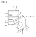
- a forcible connection preventing wall 7 projects from the front wall of the main body 3 in a middle or intermediate part of the area 4 with respect to height direction HD or radial direction (direction at an angle different from 0° or 180°, preferably substantially normal to the connecting direction with the mating connector) where the smaller terminal fittings are at least partly accommodated, and the front end position thereof preferably is substantially aligned with the front end of the receptacle 2.
- This forcible connection preventing wall 7 can interfere with a female connector housing 10 trying to be connected with the female connector in an improper posture, thereby avoiding the deformation of the tabs. Further, as shown in FIG. 1 , upside-down insertion preventing ribs 9a.
- the ribs 9a, 9b are arranged on the outer surfaces of preferably the shorter sides of the receptacle 2.
- the ribs 9a, 9b are arranged on the outer side of the receptacle 2 in a rotationally asymmetric way, so as to allow a connection only in one rotational orientation.
- one rib 9b is arranged substantially along a connecting direction CD in the middle with respect to height direction HD at one side, whereas two ribs 9a are arranged substantially along the connecting direction CD at the other side. Therefore, the upside-down insertion of the female connector housing 10 into the male connector housing 1 can be avoided.
- one cam pin 8 projects in an intermediate position (preferably substantially in the widthwise middle) on the outer surface of preferably each longer side of the receptacle 2. As described later, both cam pins 8 contribute to or assist the connection of the female and male connectors by being guided by cam grooves 12 of a slide lever or member 11.
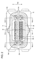
- FIG. 2 shows the female connector housing 10 integrally or unitarily made e.g. of a synthetic resin material.
- the connector housing 10 is comprised of a terminal accommodating portion 14 located at an inner side for accommodating one or more female terminal fittings 13a, 13b and an outer tube portion 15 located at an outer side and arranged to substantially surround the terminal accommodating portion 14.
- a space between the terminal accommodating portion 14 and the outer tube portion 15 serves as a connection space with the male connector housing 1.
- a seal ring 16 made of a resilient or rubber material preferably is mounted at a back end portion of the outer circumferential surface of the terminal accommodating portion 14. With the female and male connector housings connected, the seal ring 16 is substantially in close contact with the inner surface of the receptacle 2 preferably over the substantially entire circumference, thereby preferably providing sealing between the female and male connector housings.
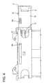
- the outer tube portion 15 has a substantially hollow structure, and the slide lever or member 11 for assisting the connecting operation of the male and female connector housings 1, 10 is at least partly accommodated inside.
- the opposite shorter sides of the outer tube portion 15 are entirely open, and the slide lever 11 is at least partly insertable laterally or in an inserting direction at an angle different from 0° or 180°, preferably substantially normal to the connecting direction CD (from right side of FIG. 4 ).
- the slide lever 11 is comprised of an operable portion 17 used to operate (e.g. insert and withdraw) the slide lever 11 and a pair of lever pieces 18 extending from the opposite ends of the operable portion 17 while facing each other, and preferably is substantially U-shaped as a whole.
- One or more, preferably two locking claws 19a, 19b are formed at positions near or at one longer side of each lever piece 18, these positions preferably being spaced apart along longitudinal direction of the lever pieces 18.
- the respective locking claws 19a, 19b are both resiliently deformable, and are preferably cantilever-shaped with ends thereof at front side with respect to a withdrawing direction of the slide lever 11 as free ends.
- the locking claws 19a, 19b are engageable with unillustrated engaging portions formed on the inner wall surfaces of the outer tube portion 15, thereby holding the slide lever 11 at two positions; an initial position and a connection ending position to be described later.
- Each lever piece 18 is formed with a cam groove 12 whose entrance is located at the longer edge of the lever piece 18 at the other side.
- the entrances of the cam grooves 12 are substantially aligned with cam-pin receiving openings 20 (see FIG. 2 ) formed preferably substantially in the widthwise middle of the front surface of the outer tube portion 15.
- cam-pin receiving openings 20 (see FIG. 2 ) formed preferably substantially in the widthwise middle of the front surface of the outer tube portion 15.
- Identified by 21 are bulging portions formed at positions of preferably both lever pieces 18 near the operable portion 17 and used for the withdrawing operation.
- identified by 22a, 22b are upside-down insertion preventing rails, which guide the connecting operation of the male and female connector housings 1, 10 by at least partly receiving the upside-down preventing ribs 9a, 9b when the male and female connector housings 1, 10 are connected in proper postures. If an attempt is made to insert the female connector housing 10 in a wrong posture, the rails 22a, 22b interfere with the ribs 9a, 9b, thereby making the connecting operation impossible. As a result, a function of letting an operator notice an erroneous connection is fulfilled.
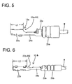
- the female terminal fittings 13a, 13b preferably are both formed by bending plate materials made of an electrically conductive material (preferably metal), and include connecting portions 22a, 22b for the connection with the male tabs t1, t2 and wire connection portions (preferably comprising barrel portions) for the connection with wires w.
- the connecting portions 22a, 22b are substantially in the form of rectangular tubes, and parts thereof can be resiliently brought into contact with the male tabs t1, t2 and can be resiliently engaged with locking portions to be described later.
- Wire barrels 24a, 24b to be crimped or bent or folded into connection with cores of the wires are provided behind the connecting portions 22a, 22b, and insulation barrels 23a, 23b are arranged behind the wire barrels 22a, 22b.
- sealing rubber plugs 25a, 25b preferably are mounted at ends of insulation coatings of the wires, and the wire barrels 24a, 24b are crimped or bent or folded into connection with the insulation coatings of the wires together with the sealing rubber plugs 25a, 25b.
- Lengths of the connecting portions 22a, 22b along forward and backward directions FBD differ (L1 > L2 shown in FIGS. 5 and 6 ) in the female terminal fittings permitting a high current (hereinafter, terminal fittings 13a for power) and the female terminal fittings whose permitted current value is set to be low (hereinafter, terminal fittings 13b e.g. for signal).
- One or more cavities 26a, 26b for at least partly accommodating the female terminal fittings 13a, 13b are arranged at one or more stages in the terminal accommodating portion 14 of the female connector housing 10. As shown in FIG. 2 , preferably a plurality, e.g. two, kinds of cavities 26a, 26b corresponding to the aforementioned female terminal fittings 13a, 13b preferably having different sizes are arranged in a mixed manner at the respective stages, and the cavities at each stage are arranged along widthwise direction with the heights thereof substantially aligned.
- One pair of the cavities for accommodating the terminal fittings 13a for power (hereinafter, "larger cavities 26a") are arranged adjacent to each other or one substantially above the other at each of the lateral sides (left and right sides in FIG.
- the cavities for at least partly accommodating the terminal fittings 13b for signal are arranged at upper and lower sides of an accommodating recess 27 for accommodating the forcible connection preventing wall 7 of the male connector housing 1 when the male and female connector housings 1, 10 are connected.
- the smaller cavities 26b located on one side (e.g. above) the accommodating recess 27 preferably are substantially aligned in a row along widthwise direction at substantially even intervals, whereas those located on another side (e.g. below) the accommodating recess 27 are arranged substantially along widthwise directions at substantially even intervals at one or more stages, e.g. two (upper and lower) stages, the phases of the smaller cavities 26 at each stage being substantially aligned with respect to height direction.
- Both larger and smaller cavities 26a, 26b penetrate the female connector housing 10 substantially along forward and backward directions FBD (see FIG. 7 ).
- a rear side of each cavity 26a, 26b is formed into a sealable tower portion 28a, 28b preferably substantially in the form of a hollow cylinder. Sealability is ensured by the sealing rubber plugs 25a, 25b at least partly inserted into the sealable tower portions 28a, 28b.
- a locking portion 29a, 29b resiliently engageable with an intermediate position of the connecting portion 22a, 22b of the corresponding female terminal fitting 13a, 13b is formed at a wall surface of the front side of each cavity 26a, 26b.
- Each locking portion 29a, 29b preferably is in the form of a cantilever whose front end is a free end, and is permitted to undergo a vertical deformation or towards and away from the respective cavity 26a, 26b.
- the locking portions 29a substantially corresponding to the terminal fittings 13a for power are formed at the lateral (bottom) surfaces of the cavities 26a as shown in FIG. 7 or 8
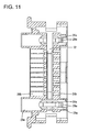
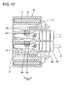
- the locking portions 29b corresponding to the terminal fittings 13b for signal are formed at the opposite lateral (ceiling) surfaces as shown in FIG. 9 .
- Each larger cavity 26a has a front wall 30a with which the front end of the terminal fitting 13a for power is brought or bringable substantially into contact (or abut) to be stopped, whereas each smaller cavity 26b preferably has no front wall and the front end of the terminal fitting 13b for signal is brought substantially into contact (or abut) with a front wall 30a of a front holder 31 to be stopped when the front holder 31 to be described later is mounted.
- a retainer insertion hole 32 is formed in a side surface preferably substantially opposite from the one where the slide lever 11 is or is to be inserted and located before the seal ring 16.
- the retainer insertion hole 32 preferably extends substantially along the widthwise direction of the terminal accommodating portion 14 (i.e. an insertion direction ID of the retainer i.e. a direction at an angle different from 0° or 180°, preferably substantially normal to the inserting direction of the respective terminal fittings).
- the retainer 33 is at least partly insertable into the retainer insertion hole 32 in an insertion direction ID at an angle different from 0° or 180°, preferably substantially normal to the forward and backward direction FBD.
- An upper and a lower openings 32a are formed in the opposite side surface of the terminal accommodating portion 14 (surface where the slide lever 11 is inserted) (see FIG. 8 ), and correspond to the leading ends of locking legs 34a, 34b of a retainer 33 to be described later.
- all the cavities 26a, 26b excluding some are divided into front and rear sections including parts of the locking portions 29a, 29b behind the base ends of the locking portions 29a, 29b (see FIGS. 7 and 8 ).
- the locking portions 29a are not divided by the retainer insertion hole 32 in only the upper and lower cavities 26a located at the back side with respect to an inserting direction of the retainer 33 as shown in FIG.
- the retainer 33 is comprised of a frame-shaped portion 35 and one or more, e.g. two, locking legs 34a, 34b having different lengths and projecting along widthwise direction from one shorter side of the frame-shaped portion 35, and the entire length of the retainer 33 along widthwise direction is set to be substantially equal to the entire width of the terminal accommodating portion 14.
- the retainer 33 is provided with one or more signal terminal locking sections 36b for locking the respective terminal fittings 13b for signal and one or more power terminal locking sections 36a for locking the terminal fittings 13a for power.
- the signal terminal locking sections 36b are such oblong openings extending along widthwise direction as to substantially communicate with all the cavities 26b at the corresponding stages, and are formed at one or more, e.g.
- each signal terminal locking section 36b one or more smaller locking projections 37b are formed at intervals substantially corresponding to those of the cavities 26b at the corresponding stage.
- the smaller locking projections 37b are at such positions as not to interfere with the terminal fittings 13b for signal.
- the retainer 33 is moved to a full locking position (as a preferred second position) they are engageable with the rear ends 22b-RE (as a preferred lockable part) of the connecting portions 22b of the terminal fittings 13b for signal.
- the power terminal locking sections 36a there are several (e.g. two) kinds of the power terminal locking sections 36a, those formed at an end portion inside the frame-shaped portion 35 and those formed at both locking legs 34a, 34b.
- Those provided inside the frame-shaped portion 35 are two lateral (upper and lower) windows formed substantially in conformity with the larger cavities 26a at the left side of FIG. 2 .
- a larger locking projection 37a projects at one corner of each window.
- larger locking projections 37a are provided at the base ends of both locking legs 34a, 34b in the power terminal locking sections 36a set at the locking legs 34a, 34b.
- the larger and smaller locking projections 37a, 37b are arranged along the longitudinal direction of the retainer 33 with the positions thereof substantially aligned with respect to forward and backward directions FBD.
- the above retainer 33 is displaceable between the partial locking position (first position) where the terminal fittings 13b for signal and the terminal fittings 13a for power are insertable and withdrawable and the full locking position (second position) where the retainer 33 is engaged with the respective terminal fittings 13a, 13b (i.e. their lockable parts 22a-RE, 22b-RE) to retain them in the cavities 26a, 26b.
- one or more retainer holding portions 38 are provided at positions of preferably both longer sides of the frame-shaped portion 35 near the locking legs 34a, 34b. As shown in FIG. 14 , the leading ends of the retainer holding portions 38 are formed, thereby being permitting to undergo such a deformation as to be narrowed.
- a partial locking or first recess 39a and a full locking or second recess 39b are formed at two positions on the outer surface of the free end of preferably each forked part.
- lock projections 40 are formed to project inward substantially in conformity with the first and second (partial and full) locking recesses 39a, 39b.
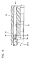
- the lock projections 40 are resiliently engaged or engageable with the partial locking recesses 39a and the full locking recesses 39b, thereby holding the entire retainer 33 at the partial locking position (first position, position shown in FIG. 14 ) and the full locking position (second position, position shown in FIG. 15 ).
- the frame-shaped portion 35 of the retainer 33 is formed with an insertion hole 41 which is substantially aligned with the accommodating recess 27 to permit the at least partial insertion of the forcible connection preventing wall 7 when the retainer 33 is at the full locking position (second position).
- the front holder 31 is made e.g. of a synthetic resin preferably substantially into a rectangular tube fittable on or to the outer circumferential surface of the front end of the terminal accommodating portion 14. Front-end portions of the smaller cavities 26b are formed in an area of the front surface of the front holder 31 to enable the terminal fittings 13b for signal to stop at their front end positions. These front-end portions are so formed as to permit the insertion of the tabs of the male terminal fittings. However, openings are formed in areas of the front surface of the front holder 31 substantially corresponding to the larger cavities 26a, and the front ends of the larger cavities 26a are caused to project forward through these openings. When the front holder 31 is mounted, the peripheral edge thereof at the rear end comes substantially into contact with the front end edge of the seal ring 16, whereby the seal ring 16 can be retained so as not to come out.
- the front holder 31 Even in a state where the front holder 31 is mounted, the area of the front surface of the front holder 31 substantially corresponding to the smaller cavities 26b and the areas thereof corresponding to the larger cavities 26a projecting from the front surface of the front holder 31 are displaced along forward and backward directions FBD, and these displacements substantially correspond to those of the front surface of the male connector housing 1. Therefore, when the male and female connector housings 1, 10 are properly connected, the corresponding front end surfaces are substantially held in contact.
- the front holder 31 Prior to the at least partial insertion of the respective terminal fittings 13a, 13b into the female connector housing 10, the front holder 31 is mounted and the retainer 33 is held at the partial locking position (first position).
- the terminal fitting 13b for signal comes substantially into contact with or abuts on the inner surface of the front wall of the front holder 31 to be stopped at its front end position and is preferably (partly) locked by the locking portion 29b.
- the terminal fitting 13a for power comes substantially into contact with or abuts on the inner surface of the front wall of the corresponding larger cavity 26a to be stopped at its front end position and preferably is similarly (partly) locked by the corresponding locking portion 29a.
- the positions of the rear ends 22b-RE of the connecting portions 22b of the respective terminal fittings 13b for signal and those of the rear ends 22aRE of the connecting portions 22a of the respective terminal fittings 13a for power are substantially aligned, i.e. distances from a plane of opening of the outer tube portion 15 to these rear ends are substantially equal. Accordingly, when the retainer 33 is displaced (pushed and moved) from the partial locking position (first position) to the full locking position (second position) thereafter, the larger and smaller locking projections 37a, 37b of the locking sections 36a, 36b of the retainer 33 are simultaneously engaged with the rear ends of the corresponding connecting portions 22a, 22b. Thus, all the terminal fittings 13a, 13b are preferably doubly locked by the locking portions 29a, 29b and the locking projections 37a, 37b.
- the respective terminal fittings 13a, 13b are held and retained in the female connector housing 10.
- the front ends of the terminal fittings 13b for signal are located slightly behind those of the terminal fittings 13a for power. This displacement corresponds to the displacement between the leading ends of the tabs t1, t2 of the larger and smaller terminal fittings of the male connector.
- the positions of the rear ends of the connecting portions 22a, 22b of the terminal fittings 13a, 13b are substantially aligned in the connector for accommodating the terminal fittings 13a, 13b whose connecting portions 22a, 22b have different lengths.
- the terminal fittings 13a, 13b can be locked by the retainer 33. Therefore, a degree of freedom in the arrangement of the terminal fittings can be improved.
- female terminal fittings 13a, 13b to be at least partly accommodated in a female connector housing, e.g. those for power and those for signal having connecting portions 22a, 22b differing in length.
- these terminal fittings 13a, 13b are at least partly inserted into corresponding cavities 26a, 26b of the female connector housing 10
- the positions of the front ends of the terminal fittings 13a, 13b are displaced along forward and backward directions FBD, thereby substantially aligning the positions of the rear ends of the connecting portions 22a, 22b along an inserting direction ID of a retainer 33.
- the retainer 33 used has a normal or usual construction in which the positions of locking sections 37a, 37b are substantially aligned, the respective terminal fittings 13a, 13b can be simultaneously locked.
Landscapes
- Engineering & Computer Science (AREA)
- Chemical & Material Sciences (AREA)
- Combustion & Propulsion (AREA)
- Mechanical Engineering (AREA)
- General Engineering & Computer Science (AREA)
- Connector Housings Or Holding Contact Members (AREA)
Description
- The present invention relates to a connector and to a connector assembly.
- Some of known connectors are of such a type in which larger and smaller terminal fittings are provided in a mixed manner in conformity with permissible current values (
Japanese Unexamined Patent Publication No. 2000-182709 -
EP 1 009 061 A2 -
US 6,364,718 B1 (D2) discloses a keying system for an electrical connector assembly including a male connector having a body portion, a mating end formed by a plurality of terminal-receiving silos extending form she body portion. -
US 6,004,158 (D3) discloses an electrical connector, especially intended for automotive applications including a receptacle connector housing and a mating plug connector housing. - If such terminal fittings are, for example, female terminal fittings, tubular connecting portions - for the connection with male terminal fittings have different volumes and different lengths along forward and backward directions. On the other hand, a retainer is normally mounted into the connector and engaged with the rear ends of the connecting portions of the respective terminal fittings to retain the terminal fittings in many cases.
- There are cases where terminal fittings whose connecting portions have different lengths along forward and backward directions as described above are mounted in a mixed manner in an arranging direction thereof in a connector. If such a mode is taken, the rear end positions of the connecting portions, i.e. parts to be engaged with a retainer are not aligned with respect to forward and backward directions. In such a case, if the retainer is of such a type that is inserted to cross an inserting direction of the terminal fittings through a side surface of a connector housing, the connecting portions of the terminal fittings may interfere with the retainer if the positions thereof are not aligned. Thus, attention has to be paid to the arrangement of the terminal fittings in the connector housing in order to avoid the interference with the retainer. Specifically, the terminal fittings having the connecting portions which are shorter along forward and backward directions and whose rear ends are located more forward are arranged at an entrance side with respect to an inserting direction of the retainer, whereas the longer terminal fittings having the connecting portions whose rear ends are located more backward are arranged at a back side with respect to the inserting direction of the retainer.
- It should be noted that the front end positions of the connecting portions of the terminal fittings, i.e. the positions of the front end surfaces of the connecting portions are aligned as a prerequisite.
- Connectors in which terminal fittings whose connecting portions have different lengths along forward and backward directions are arranged in a mixed manner have had a problem of being deprived of a degree of freedom in designing for the arrangement of the terminal fittings.
- Thus, according to an aspect, it is a problem to provide an improved connector which can be minimized in size and easier be produced.
- This object is solved according to the invention by a connector according to
claim 1. Preferred embodiments of the invention are subject of the dependent claims. - According to the invention, there is provided a connector, comprising:
- a plurality of kinds of terminal fittings whose connecting portions for the connection with mating terminal fittings have different lengths along forward and backward directions,
- a connector housing formed with a plurality of cavities arranged substantially along widthwise direction into which the terminal fittings are at least partly insertable, and
- a retainer mountable into the connector housing along an arranging direction of the cavity and simultaneously engageable with lockable parts set on the connecting portions of the respective terminal fittings upon being properly mounted, thereby retaining the respective terminal fittings in the cavities,
- Accordingly, since the positions of the lockable parts of the connecting portions are aligned, the retainer can be engaged with the lockable parts regardless of the arrangement of the terminal fittings whose connecting portions have different lengths. Thus, a degree of freedom in arranging the terminal fittings can be improved.
- According to a preferred embodiment of the invention, projected positions of the respective terminal fittings from the front end surface of the connector housing are differed depending on the lengths of the connecting portions along forward and backward directions, thereby substantially aligning the positions of the rear ends of the connecting portions with respect to an inserting direction of the terminal fittings, which rear ends are the lockable parts.
- Accordingly, since the positions of the rear ends of the connecting portions are substantially aligned to be engageable with the retainer, the construction can be simpler as compared to a case where the lockable parts are formed at intermediate positions of the connecting portions.
- Further preferably, the retainer can be positioned at a first position, where the insertion and withdrawal of the terminal fittings to and from the respective cavities is permitted, and a second position, where the terminal fittings are locked in the respective cavities.
- Most preferably, an area of a front surface of the front holder, preferably substantially corresponding to the cavities projecting from the front surface of the front holder, is displaced along forward and backward directions.
- According to a further preferred embodiment of the invention, the connector comprises a plurality of locking portions for locking the respective terminal fittings in the respective cavities.
- Preferably, the locking portions substantially have cranked shape, wherein a free length of the locking portions at one side is made shorter than that of the locking portions at the other side along an inserting direction of the retainer and/or the locking portions at one side are made thicker than the locking portions at other side.
- There is further provided a connector assembly comprising a connector according to the invention or a preferred embodiment thereof and a mating connector, wherein the terminal fittings are retained in the connector housing with front ends of the terminal fittings of one kind being located slightly behind those of the terminal fittings of the other kind, and
wherein the displacement of the terminal fittings corresponds to a displacement between the leading ends of mating terminal fittings of the mating connector. - One of the connector and the mating connector comprise a forcible connection preventing wall which projects from a main body thereof and can interfere with the other of the connector and the mating connector when trying connect the connector and the mating connector in an improper posture.
- Preferably, the forcible connection preventing wall is provided on the mating connector and the retainer is formed with an insertion hole to permit the at least partial insertion of the forcible connection preventing wall when the retainer locks the terminal fittings.
- These and other objects, features and advantages of the present invention will become more apparent upon reading of the following detailed description of preferred embodiments and accompanying drawings. It should be understood that even though embodiments are separately described, single features thereof may be combined to additional embodiments.
-
FIG. 1 is a front view of a male connector housing, -
FIG. 2 is a front view of a female connector housing, -
FIG. 3 is a section showing an essential portion of a forcibly connecting state of the male and female connector housings, -
FIG. 4 is a side view showing a connecting operation of the male and female connector housings, -
FIG. 5 is a side view showing a terminal fitting for power, -
FIG. 6 is a side view showing a terminal fitting for signal, -
FIG. 7 is a section along VII-VII ofFIG. 2 , -
FIG. 8 is a section along VIII-VIII ofFIG. 2 , -
FIG. 9 is a section along IX-IX ofFIG. 2 , -
FIG. 10 is a section along X-X ofFIG. 2 , -
FIG. 11 is a section along XI-XI ofFIG. 2 , -
FIG. 12 is a front view of a retainer showing a relationship with terminal fittings when the retainer is at a partial locking position, -
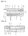
FIG. 13 is a front view of the retainer showing a relationship with the terminal fittings when the retainer is at a full locking position, -
FIG. 14 is a section showing a state where the retainer is at the partial locking position, -
FIG. 15 is a section showing a state where the retainer is at the full locking position, -
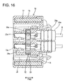
FIG. 16 is a section, corresponding toFIG. 7 , showing a state where the re- tainer and a front holder are mounted, -
FIG. 17 is a section corresponding toFIG. 8 , and -
FIG. 18 is a section corresponding toFIG. 9 . - One preferred embodiment of the present invention is described with reference to the accompanying drawings. In the following description, a mating side of the connector with a mating connector is referred to as front or front side. In this embodiment, a connector preferably of the so-called hybrid type in which one or more larger and smaller terminal fittings are at least partly accommodated in a mixed manner (regular/unregular) is described as an example.
FIG. 1 shows a connector housing 1 (preferably made of a synthetic resin) of a male connector. Themale connector housing 1 includes atubular receptacle 2 having an open front surface and at least partly surrounding a space before a main body 3 for at least partly accommodating one or more male terminal fittings (not shown). Preferably a plurality, e.g. two kinds of male terminal fittings, i.e. larger and smaller male terminal fittings are at least partly accommodated in the main body 3, wherein the larger male terminal fittings (as a preferred first type terminal fitting) are accommodated at one or more stages, preferably at two (upper and lower) stages at the lateral (left and right) sides and the smaller male terminal fittings (as a preferred second type terminal fitting) are at least partly accommodated at one or more stages, preferably at three stages between the larger male terminal fittings inFIG. 1 . Tabs of these male terminal fittings at least partly project into thereceptacle 2 from the front wall of the main body 3, thereby preferably being substantially protected by thereceptacle 2. The front wall of the main body 3 is comprised of a middle orintermediate area 4 where the smaller terminal fittings are at least partly accommodated and lateral (left and right)areas 5 located at the substantially opposite lateral (left and right) sides of thearea 4 for at least partly accommodating the larger terminal fittings. Although not shown in detail, one or more steps orslanted surfaces 6 are set between the middle orintermediate area 4 and the lateral (left and right)areas 5 so that themiddle area 4 projects more forward than the left andright areas 5. Accordingly, the front end positions of tabs t1 (smaller terminal fittings) projecting from themiddle area 4 preferably are located more forward than those of tabs t2 (larger terminal fittings) projecting from the left andright areas 5. - A forcible
connection preventing wall 7 projects from the front wall of the main body 3 in a middle or intermediate part of thearea 4 with respect to height direction HD or radial direction (direction at an angle different from 0° or 180°, preferably substantially normal to the connecting direction with the mating connector) where the smaller terminal fittings are at least partly accommodated, and the front end position thereof preferably is substantially aligned with the front end of thereceptacle 2. This forcibleconnection preventing wall 7 can interfere with afemale connector housing 10 trying to be connected with the female connector in an improper posture, thereby avoiding the deformation of the tabs. Further, as shown inFIG. 1 , upside-down insertion preventing ribs 9a. 9b are arranged on the outer surfaces of preferably the shorter sides of thereceptacle 2. Theribs 9a, 9b are arranged on the outer side of thereceptacle 2 in a rotationally asymmetric way, so as to allow a connection only in one rotational orientation. InFIG. 1 , onerib 9b is arranged substantially along a connecting direction CD in the middle with respect to height direction HD at one side, whereas two ribs 9a are arranged substantially along the connecting direction CD at the other side. Therefore, the upside-down insertion of thefemale connector housing 10 into themale connector housing 1 can be avoided. - Further, one
cam pin 8 projects in an intermediate position (preferably substantially in the widthwise middle) on the outer surface of preferably each longer side of thereceptacle 2. As described later, both cam pins 8 contribute to or assist the connection of the female and male connectors by being guided bycam grooves 12 of a slide lever ormember 11. - Next, the female connector connectable substantially along the connection direction CD with the aforementioned male connector is described.
FIG. 2 shows thefemale connector housing 10 integrally or unitarily made e.g. of a synthetic resin material. Theconnector housing 10 is comprised of aterminal accommodating portion 14 located at an inner side for accommodating one or more femaleterminal fittings outer tube portion 15 located at an outer side and arranged to substantially surround theterminal accommodating portion 14. A space between the terminal accommodatingportion 14 and theouter tube portion 15 serves as a connection space with themale connector housing 1. As shown inFIG. 16 and other figures, aseal ring 16 made of a resilient or rubber material preferably is mounted at a back end portion of the outer circumferential surface of theterminal accommodating portion 14. With the female and male connector housings connected, theseal ring 16 is substantially in close contact with the inner surface of thereceptacle 2 preferably over the substantially entire circumference, thereby preferably providing sealing between the female and male connector housings. - The
outer tube portion 15 has a substantially hollow structure, and the slide lever ormember 11 for assisting the connecting operation of the male andfemale connector housings outer tube portion 15 are entirely open, and theslide lever 11 is at least partly insertable laterally or in an inserting direction at an angle different from 0° or 180°, preferably substantially normal to the connecting direction CD (from right side ofFIG. 4 ). Theslide lever 11 is comprised of anoperable portion 17 used to operate (e.g. insert and withdraw) theslide lever 11 and a pair oflever pieces 18 extending from the opposite ends of theoperable portion 17 while facing each other, and preferably is substantially U-shaped as a whole. - One or more, preferably two locking
claws lever piece 18, these positions preferably being spaced apart along longitudinal direction of thelever pieces 18. Therespective locking claws slide lever 11 as free ends. The lockingclaws outer tube portion 15, thereby holding theslide lever 11 at two positions; an initial position and a connection ending position to be described later. - Each
lever piece 18 is formed with acam groove 12 whose entrance is located at the longer edge of thelever piece 18 at the other side. When theslide lever 11 is at the initial position, the entrances of thecam grooves 12 are substantially aligned with cam-pin receiving openings 20 (seeFIG. 2 ) formed preferably substantially in the widthwise middle of the front surface of theouter tube portion 15. Thus, when the male andfemale connector housings cam grooves 12 via the cam-pin receiving openings 20. When theslide lever 11 is pushed into theouter tube portion 15 from the initial position, the cam pins 8 are guided toward the back ends of thecam grooves 12 by the cam function thereof with thecam grooves 12. When theslide lever 11 is pushed up to the connection ending position, the male andfemale connector housings - Identified by 21 are bulging portions formed at positions of preferably both
lever pieces 18 near theoperable portion 17 and used for the withdrawing operation. Further, identified by 22a, 22b are upside-down insertion preventing rails, which guide the connecting operation of the male andfemale connector housings ribs 9a, 9b when the male andfemale connector housings female connector housing 10 in a wrong posture, therails ribs 9a, 9b, thereby making the connecting operation impossible. As a result, a function of letting an operator notice an erroneous connection is fulfilled. - Next, the female
terminal fittings terminal accommodating portion 14 are described. In this embodiment, preferably two kinds of female terminal fittings, e.g. larger and smaller terminal fittings, are used in conformity with permissible current values (seeFIGS. 5 and 6 ). The femaleterminal fittings portions portions Wire barrels portions insulation barrels wire barrels rubber plugs wire barrels rubber plugs - Lengths of the connecting
portions FIGS. 5 and 6 ) in the female terminal fittings permitting a high current (hereinafter,terminal fittings 13a for power) and the female terminal fittings whose permitted current value is set to be low (hereinafter,terminal fittings 13b e.g. for signal). - One or
more cavities terminal fittings terminal accommodating portion 14 of thefemale connector housing 10. As shown inFIG. 2 , preferably a plurality, e.g. two, kinds ofcavities terminal fittings terminal fittings 13a for power (hereinafter, "larger cavities 26a") are arranged adjacent to each other or one substantially above the other at each of the lateral sides (left and right sides inFIG. 2 ) with the phases thereof preferably substantially aligned along vertical or height direction HD. On the other hand, the cavities for at least partly accommodating theterminal fittings 13b for signal (hereinafter, "smaller cavities 26b") are arranged at upper and lower sides of anaccommodating recess 27 for accommodating the forcibleconnection preventing wall 7 of themale connector housing 1 when the male andfemale connector housings smaller cavities 26b located on one side (e.g. above) theaccommodating recess 27 preferably are substantially aligned in a row along widthwise direction at substantially even intervals, whereas those located on another side (e.g. below) theaccommodating recess 27 are arranged substantially along widthwise directions at substantially even intervals at one or more stages, e.g. two (upper and lower) stages, the phases of the smaller cavities 26 at each stage being substantially aligned with respect to height direction. - Both larger and
smaller cavities female connector housing 10 substantially along forward and backward directions FBD (seeFIG. 7 ). A rear side of eachcavity sealable tower portion rubber plugs sealable tower portions portion portion cavity portion respective cavity portions 29a substantially corresponding to theterminal fittings 13a for power are formed at the lateral (bottom) surfaces of thecavities 26a as shown inFIG. 7 or8 , whereas the lockingportions 29b corresponding to theterminal fittings 13b for signal are formed at the opposite lateral (ceiling) surfaces as shown inFIG. 9 . Eachlarger cavity 26a has afront wall 30a with which the front end of the terminal fitting 13a for power is brought or bringable substantially into contact (or abut) to be stopped, whereas eachsmaller cavity 26b preferably has no front wall and the front end of the terminal fitting 13b for signal is brought substantially into contact (or abut) with afront wall 30a of afront holder 31 to be stopped when thefront holder 31 to be described later is mounted. - As is clear from
FIGS. 7 to 9 , in thefemale connector housing 10 alone before thefront holder 31 is mounted, areas of the front end surface of theterminal accommodating portion 14 substantially corresponding to thelarger cavities 26a, i.e. areas at the substantially opposite widthwise ends are substantially in flush with the front end edge of theouter tube portion 15, but an area thereof corresponding to thesmaller cavities 26b, i.e. a middle or intermediate area is retracted backward from the front end edge of theouter tube portion 15. When theterminal fittings cavities portions terminal fittings - In the
terminal accommodating portion 14, aretainer insertion hole 32 is formed in a side surface preferably substantially opposite from the one where theslide lever 11 is or is to be inserted and located before theseal ring 16. Theretainer insertion hole 32 preferably extends substantially along the widthwise direction of the terminal accommodating portion 14 (i.e. an insertion direction ID of the retainer i.e. a direction at an angle different from 0° or 180°, preferably substantially normal to the inserting direction of the respective terminal fittings). In other words, theretainer 33 is at least partly insertable into theretainer insertion hole 32 in an insertion direction ID at an angle different from 0° or 180°, preferably substantially normal to the forward and backward direction FBD. An upper and alower openings 32a are formed in the opposite side surface of the terminal accommodating portion 14 (surface where theslide lever 11 is inserted) (seeFIG. 8 ), and correspond to the leading ends of lockinglegs retainer 33 to be described later. By forming the aboveretainer insertion hole 32 in theterminal accommodating portion 14, all thecavities portions portions FIGS. 7 and8 ). Out of thelarger cavities 26a, the lockingportions 29a are not divided by theretainer insertion hole 32 in only the upper andlower cavities 26a located at the back side with respect to an inserting direction of theretainer 33 as shown inFIG. 9 . If a large opening should be formed instead of the upper andlower openings 32a, the strength of theterminal accommodating portion 14 is reduced. However, withsuch openings 32a, deformability differs between the lockingportions 29a in thelarger cavities 26a located at the left side inFIG. 2 and those in thelarger cavities 26a at the right side. As a result, inserting forces exerted to the femaleterminal fittings 13a are unbalanced between the left and rightlarger cavities 26a. Accordingly, in this embodiment, the free length (dimension from the base end of the locking portion to the locking surface inFIG. 7 or the length of the lever performing the lever action for locking) of the lockingportions 29a in thelarger cavities 26a at the one (left) side is made shorter than that of the locking portions in thelarger cavities 26a at the other (right) side and theformer locking portions 29a are made thicker than thelatter locking portions 29a. In this way, the lockingportions 29a in the lateral (left and right)larger cavities 26a are made to have substantially equal deformability. - As shown in
FIG. 13 , theretainer 33 is comprised of a frame-shapedportion 35 and one or more, e.g. two, lockinglegs portion 35, and the entire length of theretainer 33 along widthwise direction is set to be substantially equal to the entire width of theterminal accommodating portion 14. Theretainer 33 is provided with one or more signalterminal locking sections 36b for locking the respectiveterminal fittings 13b for signal and one or more powerterminal locking sections 36a for locking theterminal fittings 13a for power. The signalterminal locking sections 36b are such oblong openings extending along widthwise direction as to substantially communicate with all thecavities 26b at the corresponding stages, and are formed at one or more, e.g. three stages. In each signalterminal locking section 36b, one or moresmaller locking projections 37b are formed at intervals substantially corresponding to those of thecavities 26b at the corresponding stage. When theretainer 33 is at a partial locking position (as a preferred first position) to be described later, thesmaller locking projections 37b are at such positions as not to interfere with theterminal fittings 13b for signal. However, when theretainer 33 is moved to a full locking position (as a preferred second position), they are engageable with the rear ends 22b-RE (as a preferred lockable part) of the connectingportions 22b of theterminal fittings 13b for signal. - There are several (e.g. two) kinds of the power
terminal locking sections 36a, those formed at an end portion inside the frame-shapedportion 35 and those formed at both lockinglegs portion 35 are two lateral (upper and lower) windows formed substantially in conformity with thelarger cavities 26a at the left side ofFIG. 2 . Alarger locking projection 37a projects at one corner of each window. On the other hand,larger locking projections 37a are provided at the base ends of both lockinglegs terminal locking sections 36a set at the lockinglegs smaller locking projections retainer 33 with the positions thereof substantially aligned with respect to forward and backward directions FBD. - The
above retainer 33 is displaceable between the partial locking position (first position) where theterminal fittings 13b for signal and theterminal fittings 13a for power are insertable and withdrawable and the full locking position (second position) where theretainer 33 is engaged with the respectiveterminal fittings lockable parts 22a-RE, 22b-RE) to retain them in thecavities retainer holding portions 38 are provided at positions of preferably both longer sides of the frame-shapedportion 35 near the lockinglegs FIG. 14 , the leading ends of theretainer holding portions 38 are formed, thereby being permitting to undergo such a deformation as to be narrowed. A partial locking orfirst recess 39a and a full locking orsecond recess 39b are formed at two positions on the outer surface of the free end of preferably each forked part. At the walls of theretainer insertion hole 32,lock projections 40 are formed to project inward substantially in conformity with the first and second (partial and full) lockingrecesses lock projections 40 are resiliently engaged or engageable with thepartial locking recesses 39a and the full locking recesses 39b, thereby holding theentire retainer 33 at the partial locking position (first position, position shown inFIG. 14 ) and the full locking position (second position, position shown inFIG. 15 ). - The frame-shaped
portion 35 of theretainer 33 is formed with aninsertion hole 41 which is substantially aligned with theaccommodating recess 27 to permit the at least partial insertion of the forcibleconnection preventing wall 7 when theretainer 33 is at the full locking position (second position). - The
front holder 31 is made e.g. of a synthetic resin preferably substantially into a rectangular tube fittable on or to the outer circumferential surface of the front end of theterminal accommodating portion 14. Front-end portions of thesmaller cavities 26b are formed in an area of the front surface of thefront holder 31 to enable theterminal fittings 13b for signal to stop at their front end positions. These front-end portions are so formed as to permit the insertion of the tabs of the male terminal fittings. However, openings are formed in areas of the front surface of thefront holder 31 substantially corresponding to thelarger cavities 26a, and the front ends of thelarger cavities 26a are caused to project forward through these openings. When thefront holder 31 is mounted, the peripheral edge thereof at the rear end comes substantially into contact with the front end edge of theseal ring 16, whereby theseal ring 16 can be retained so as not to come out. - Even in a state where the
front holder 31 is mounted, the area of the front surface of thefront holder 31 substantially corresponding to thesmaller cavities 26b and the areas thereof corresponding to thelarger cavities 26a projecting from the front surface of thefront holder 31 are displaced along forward and backward directions FBD, and these displacements substantially correspond to those of the front surface of themale connector housing 1. Therefore, when the male andfemale connector housings - Next, functions and effects of this embodiment constructed as above are specifically described.
- Prior to the at least partial insertion of the respective
terminal fittings female connector housing 10, thefront holder 31 is mounted and theretainer 33 is held at the partial locking position (first position). When the terminal fitting 13b for signal is at least partly inserted into thesmaller cavity 26b in this state, the terminal fitting 13b for signal comes substantially into contact with or abuts on the inner surface of the front wall of thefront holder 31 to be stopped at its front end position and is preferably (partly) locked by the lockingportion 29b. The terminal fitting 13a for power comes substantially into contact with or abuts on the inner surface of the front wall of the correspondinglarger cavity 26a to be stopped at its front end position and preferably is similarly (partly) locked by the corresponding lockingportion 29a. At this time, the positions of the rear ends 22b-RE of the connectingportions 22b of the respectiveterminal fittings 13b for signal and those of the rear ends 22aRE of the connectingportions 22a of the respectiveterminal fittings 13a for power are substantially aligned, i.e. distances from a plane of opening of theouter tube portion 15 to these rear ends are substantially equal. Accordingly, when theretainer 33 is displaced (pushed and moved) from the partial locking position (first position) to the full locking position (second position) thereafter, the larger andsmaller locking projections sections retainer 33 are simultaneously engaged with the rear ends of the corresponding connectingportions terminal fittings portions projections - As described above, the respective
terminal fittings female connector housing 10. At this time, the front ends of theterminal fittings 13b for signal are located slightly behind those of theterminal fittings 13a for power. This displacement corresponds to the displacement between the leading ends of the tabs t1, t2 of the larger and smaller terminal fittings of the male connector. Thus, when the male andfemale connector housings terminal fittings terminal fittings - As described above, according to this embodiment, the positions of the rear ends of the connecting
portions terminal fittings terminal fittings portions terminal fittings terminal fittings retainer 33. Therefore, a degree of freedom in the arrangement of the terminal fittings can be improved. - Accordingly, to improve a degree of freedom in arranging terminal fittings, there are two kinds of female
terminal fittings portions terminal fittings cavities female connector housing 10, the positions of the front ends of theterminal fittings portions retainer 33. Thus, even if theretainer 33 used has a normal or usual construction in which the positions of lockingsections terminal fittings - The present invention is not limited to the above described and illustrated embodiment. For example, the following embodiments are also embraced by the technical scope of the present invention as defined by the claims. Beside the following embodiments, various changes can be made without departing from the scope of the present invention as defined by the claims.
- (1) Although the present invention is applied to the female connector in the foregoing embodiment, it may be applicable to male connectors.
- (2) Parts to be locked by the retainer may not necessarily be the rear ends of the connecting portions. For example, the connecting portions may be locked at their intermediate positions by the retainer.
- (3) According to the invention, the terminal fittings may be locked by either one of the locking portions or the retainer, only.
- (4) Even though in the above described preferred embodiment the retainer locks a rear portion of the connection portions as a preferred lockable parts, the invention is applicable also to connectors or terminal fittings in which the retainer locks a different lockable part such as a locking projection,locking step or the like.
-
- 10 ..
- female connector housing
- 13a ..
- terminal fitting for power
- 13b ...
- terminal fitting for signal
- 22a, 22b...
- connecting portion
- 26a, 26b...
- large, smaller cavities
- 32 ...
- retainer insertion hole
- 33 ...
- retainer
characterized in that
a front holder is mountable on the connector housing to define abutment portions for at least part of the cavities against which the terminal fittings can abut upon substantially proper insertion into the respective cavity.
Claims (6)
- A connector, comprising:a plurality of kinds of terminal fittings (13a, 13b) whose connecting portions (22a, 22b) for the connection with mating terminal fittings have different lengths (L1, L2) along forward and backward directions (FBD),a connector housing (10), formed with a plurality of cavities (26a, 26b) arranged substantially along widthwise direction into which the terminal fittings (13a, 13b) are at least partly insertable, anda retainer (33) is mountable into the connector housing (10) along an arranging direction of the cavities (26a, 26b) and simultaneously engageable with lockable parts (22a-RE, 22b-RE) set on the connecting portions (22a, 22b) of the respective terminal fittings (13a, 13b) upon being properly mounted, thereby retaining the respective terminal fittings (13a, 13b) in the cavities (26a, 26b),wherein the respective terminal fittings (13a, 13b) are accommodated in the cavities (26a, 26b) with the positions of the respective lockable parts (22a-RE, 22b-RE) substantially aligned with respect to forward and backward directions (FBD),
characterized in thata front holder (31) is mountable on the connector housing (10) to define abutment portions for at least part of the cavities (26a, 26b) against which the terminal fittings (13a, 13b) can abut upon substantially proper insertion into the respective cavity (26a, 26b). - A connector according to claim 1, wherein projected positions of the respective terminal fittings (13a, 13b) from the front end surface of the connector housing (10) are differed depending on the lengths (L1, L2) of the connecting portions (22a, 22b) along forward and backward directions (FBD), thereby aligning the positions of the rear ends (22a-RE, 22b-RE) of the connecting portions (22a, 22b) with respect to an inserting direction of the terminal fittings (13a, 13b), which rear ends (22a-RE, 22b-RE) are the lockable parts.
- A connector according to one or more of the preceding claims, wherein she retainer (33) can be positioned at a first position, where the insertion and withdrawl of the terminal fittings (13a, 13b) to and from the respective cavities (26a, 26b) is permitted, and a second position, where the terminal fittings (13a, 13b) are locked in the respective cavities (26a, 26b).
- A connector according to claim 1, wherein an area of a front surface of the front holder (31), preferably substantially corresponding to the cavities (26a, 26b) projecting from the front surface of the front holder (31), is displaced along forward and backward directions (FBD).
- A connector according to one or more of the preceding claims, wherein the connector (10) comprises a plurality of locking portions (29a, 29b) for locking the respective terminal fittings (13a, 13b) in the respective cavities (26a, 26b).
- A connector according to claim 5, wherein the locking portions (29a, 29b) substantially have cranked shape, wherein a free length of the locking portions (29a) at one side is made shorter than that of the locking portions at the other side along an inserting direction (ID) of the retainer (33) and/or the locking portions (29a) at one side are made thicker than the locking portions (29a) at other side.
Applications Claiming Priority (2)
| Application Number | Priority Date | Filing Date | Title |
|---|---|---|---|
| JP2004118649 | 2004-04-14 | ||
| JP2004118649A JP4349186B2 (en) | 2004-04-14 | 2004-04-14 | connector |
Publications (2)
| Publication Number | Publication Date |
|---|---|
| EP1587174A1 EP1587174A1 (en) | 2005-10-19 |
| EP1587174B1 true EP1587174B1 (en) | 2010-04-07 |
Family
ID=34935055
Family Applications (1)
| Application Number | Title | Priority Date | Filing Date |
|---|---|---|---|
| EP05008000A Ceased EP1587174B1 (en) | 2004-04-14 | 2005-04-12 | A connector and a connector assembly |
Country Status (6)
| Country | Link |
|---|---|
| US (1) | US7114999B2 (en) |
| EP (1) | EP1587174B1 (en) |
| JP (1) | JP4349186B2 (en) |
| KR (1) | KR100644179B1 (en) |
| CN (1) | CN100566041C (en) |
| DE (1) | DE602005020384D1 (en) |
Families Citing this family (14)
| Publication number | Priority date | Publication date | Assignee | Title |
|---|---|---|---|---|
| DE602006004152D1 (en) * | 2005-12-20 | 2009-01-22 | Sumitomo Wiring Systems | Connector and connector assembly |
| JP4755940B2 (en) * | 2006-05-23 | 2011-08-24 | 矢崎総業株式会社 | connector |
| US7241156B1 (en) * | 2006-07-31 | 2007-07-10 | Delphi Technologies, Inc. | Electrical connector with cam lever retainer |
| JP4760683B2 (en) * | 2006-11-20 | 2011-08-31 | 住友電装株式会社 | connector |
| JP4849007B2 (en) * | 2007-05-21 | 2011-12-28 | 住友電装株式会社 | connector |
| JP5217458B2 (en) * | 2008-01-29 | 2013-06-19 | 住友電装株式会社 | connector |
| JP5238481B2 (en) * | 2008-12-26 | 2013-07-17 | タイコエレクトロニクスジャパン合同会社 | Electrical connector |
| JP5494381B2 (en) * | 2010-09-14 | 2014-05-14 | 住友電装株式会社 | connector |
| JP6015628B2 (en) | 2013-10-31 | 2016-10-26 | 住友電装株式会社 | connector |
| JP6198793B2 (en) * | 2015-09-16 | 2017-09-20 | 矢崎総業株式会社 | connector |
| JP6485317B2 (en) * | 2015-10-20 | 2019-03-20 | 住友電装株式会社 | Wire harness |
| JP7155987B2 (en) * | 2018-12-14 | 2022-10-19 | 住友電装株式会社 | harness parts |
| CN116885476B (en) * | 2023-07-31 | 2024-04-05 | 浙江珠城科技股份有限公司 | Strong and weak electricity multi-line set connector |
| CN117543261B (en) * | 2023-11-10 | 2025-04-08 | 浙江珠城科技股份有限公司 | Multi-circuit motor and differential lock control connector |
Family Cites Families (10)
| Publication number | Priority date | Publication date | Assignee | Title |
|---|---|---|---|---|
| US6004158A (en) * | 1997-03-27 | 1999-12-21 | The Whitaker Corporation | Electrical connector with secondary locking plates |
| US6171146B1 (en) * | 1998-02-19 | 2001-01-09 | Delphi Technologies, Inc. | Repair method for dual lock multi-row electrical connector system |
| US6155850A (en) * | 1998-09-25 | 2000-12-05 | The Whitaker Corporation | Cam slide electrical connector |
| JP3852648B2 (en) * | 1998-12-09 | 2006-12-06 | 住友電装株式会社 | connector |
| JP2000182709A (en) | 1998-12-15 | 2000-06-30 | Sumitomo Wiring Syst Ltd | Connector with retainer |
| JP3463636B2 (en) * | 1999-12-13 | 2003-11-05 | 住友電装株式会社 | connector |
| JP3672229B2 (en) * | 2000-02-23 | 2005-07-20 | 矢崎総業株式会社 | Holder removal prevention connector |
| DE10017868B4 (en) * | 2000-04-11 | 2004-03-04 | Leopold Kostal Gmbh & Co. Kg | Electrical connector part |
| US6364718B1 (en) * | 2001-02-02 | 2002-04-02 | Molex Incorporated | Keying system for electrical connector assemblies |
| JP3994931B2 (en) | 2003-06-13 | 2007-10-24 | 住友電装株式会社 | connector |
-
2004
- 2004-04-14 JP JP2004118649A patent/JP4349186B2/en not_active Expired - Lifetime
-
2005
- 2005-04-12 US US11/104,053 patent/US7114999B2/en not_active Expired - Lifetime
- 2005-04-12 EP EP05008000A patent/EP1587174B1/en not_active Ceased
- 2005-04-12 DE DE602005020384T patent/DE602005020384D1/en not_active Expired - Lifetime
- 2005-04-14 KR KR1020050031061A patent/KR100644179B1/en not_active Expired - Fee Related
- 2005-04-14 CN CNB2005100651978A patent/CN100566041C/en not_active Expired - Fee Related
Also Published As
| Publication number | Publication date |
|---|---|
| JP2005302587A (en) | 2005-10-27 |
| JP4349186B2 (en) | 2009-10-21 |
| KR20060045710A (en) | 2006-05-17 |
| KR100644179B1 (en) | 2006-11-10 |
| EP1587174A1 (en) | 2005-10-19 |
| DE602005020384D1 (en) | 2010-05-20 |
| US7114999B2 (en) | 2006-10-03 |
| CN100566041C (en) | 2009-12-02 |
| CN1684309A (en) | 2005-10-19 |
| US20050233652A1 (en) | 2005-10-20 |
Similar Documents
| Publication | Publication Date | Title |
|---|---|---|
| EP1211757B1 (en) | Elektrical connector | |
| EP1990869B1 (en) | A connector and assembling method thereof | |
| US8052489B2 (en) | Connector | |
| US6948978B2 (en) | Connector and a method of assembling such connector | |
| US7156698B2 (en) | Waterlight connector | |
| US7204725B2 (en) | Connector and method of assembling it | |
| US7722381B2 (en) | Connector | |
| EP1587174B1 (en) | A connector and a connector assembly | |
| US7488221B2 (en) | Connector | |
| US8708739B2 (en) | Connector | |
| US6769934B2 (en) | Connector and an unlocking jig therefor | |
| US6520788B2 (en) | Watertight connector and sealing member | |
| EP0978905B1 (en) | Connector | |
| US6817901B2 (en) | Connector | |
| US8506328B2 (en) | Connector | |
| US6641437B2 (en) | Connector | |
| EP1261075B1 (en) | A watertight connector and a method for mounting it | |
| US7001206B2 (en) | Connector and a connector assembly | |
| US7306486B2 (en) | Connector | |
| EP1801926B1 (en) | A connetor and connector assembly | |
| EP1085612A1 (en) | A connector |
Legal Events
| Date | Code | Title | Description |
|---|---|---|---|
| PUAI | Public reference made under article 153(3) epc to a published international application that has entered the european phase |
Free format text: ORIGINAL CODE: 0009012 |
|
| 17P | Request for examination filed |
Effective date: 20050421 |
|
| AK | Designated contracting states |
Kind code of ref document: A1 Designated state(s): AT BE BG CH CY CZ DE DK EE ES FI FR GB GR HU IE IS IT LI LT LU MC NL PL PT RO SE SI SK TR |
|
| AX | Request for extension of the european patent |
Extension state: AL BA HR LV MK YU |
|
| AKX | Designation fees paid |
Designated state(s): DE FR |
|
| 17Q | First examination report despatched |
Effective date: 20080207 |
|
| GRAP | Despatch of communication of intention to grant a patent |
Free format text: ORIGINAL CODE: EPIDOSNIGR1 |
|
| GRAS | Grant fee paid |
Free format text: ORIGINAL CODE: EPIDOSNIGR3 |
|
| GRAA | (expected) grant |
Free format text: ORIGINAL CODE: 0009210 |
|
| AK | Designated contracting states |
Kind code of ref document: B1 Designated state(s): DE FR |
|
| REF | Corresponds to: |
Ref document number: 602005020384 Country of ref document: DE Date of ref document: 20100520 Kind code of ref document: P |
|
| PLBE | No opposition filed within time limit |
Free format text: ORIGINAL CODE: 0009261 |
|
| STAA | Information on the status of an ep patent application or granted ep patent |
Free format text: STATUS: NO OPPOSITION FILED WITHIN TIME LIMIT |
|
| 26N | No opposition filed |
Effective date: 20110110 |
|
| REG | Reference to a national code |
Ref country code: FR Ref legal event code: PLFP Year of fee payment: 12 |
|
| REG | Reference to a national code |
Ref country code: FR Ref legal event code: PLFP Year of fee payment: 13 |
|
| REG | Reference to a national code |
Ref country code: DE Ref legal event code: R084 Ref document number: 602005020384 Country of ref document: DE |
|
| REG | Reference to a national code |
Ref country code: FR Ref legal event code: PLFP Year of fee payment: 14 |
|
| PGFP | Annual fee paid to national office [announced via postgrant information from national office to epo] |
Ref country code: FR Payment date: 20200312 Year of fee payment: 16 |
|
| PGFP | Annual fee paid to national office [announced via postgrant information from national office to epo] |
Ref country code: DE Payment date: 20200331 Year of fee payment: 16 |
|
| REG | Reference to a national code |
Ref country code: DE Ref legal event code: R119 Ref document number: 602005020384 Country of ref document: DE |
|
| PG25 | Lapsed in a contracting state [announced via postgrant information from national office to epo] |
Ref country code: DE Free format text: LAPSE BECAUSE OF NON-PAYMENT OF DUE FEES Effective date: 20211103 Ref country code: FR Free format text: LAPSE BECAUSE OF NON-PAYMENT OF DUE FEES Effective date: 20210430 |