EP1024387A2 - Zoomobjektiv mit grossem Brennpunktsabstand von der Linsenrückseite und Funktion zur Reduktion von Vibrationen - Google Patents
Zoomobjektiv mit grossem Brennpunktsabstand von der Linsenrückseite und Funktion zur Reduktion von Vibrationen Download PDFInfo
- Publication number
- EP1024387A2 EP1024387A2 EP00300570A EP00300570A EP1024387A2 EP 1024387 A2 EP1024387 A2 EP 1024387A2 EP 00300570 A EP00300570 A EP 00300570A EP 00300570 A EP00300570 A EP 00300570A EP 1024387 A2 EP1024387 A2 EP 1024387A2
- Authority
- EP
- European Patent Office
- Prior art keywords
- lens group
- lens
- focal length
- vibration reduction
- zoom
- Prior art date
- Legal status (The legal status is an assumption and is not a legal conclusion. Google has not performed a legal analysis and makes no representation as to the accuracy of the status listed.)
- Withdrawn
Links
- 230000009467 reduction Effects 0.000 title claims abstract description 105
- 230000003287 optical effect Effects 0.000 claims abstract description 64
- 238000006073 displacement reaction Methods 0.000 claims description 27
- 239000002131 composite material Substances 0.000 claims description 7
- 238000003384 imaging method Methods 0.000 abstract description 37
- 230000004075 alteration Effects 0.000 description 58
- 230000005499 meniscus Effects 0.000 description 18
- 206010010071 Coma Diseases 0.000 description 13
- 230000000694 effects Effects 0.000 description 13
- 238000010276 construction Methods 0.000 description 10
- 201000009310 astigmatism Diseases 0.000 description 5
- 230000007423 decrease Effects 0.000 description 4
- 230000002093 peripheral effect Effects 0.000 description 4
- NAWXUBYGYWOOIX-SFHVURJKSA-N (2s)-2-[[4-[2-(2,4-diaminoquinazolin-6-yl)ethyl]benzoyl]amino]-4-methylidenepentanedioic acid Chemical compound C1=CC2=NC(N)=NC(N)=C2C=C1CCC1=CC=C(C(=O)N[C@@H](CC(=C)C(O)=O)C(O)=O)C=C1 NAWXUBYGYWOOIX-SFHVURJKSA-N 0.000 description 3
- 238000005516 engineering process Methods 0.000 description 3
- 239000007787 solid Substances 0.000 description 3
- 230000008859 change Effects 0.000 description 2
- 238000004519 manufacturing process Methods 0.000 description 2
- 230000007246 mechanism Effects 0.000 description 2
- 238000000034 method Methods 0.000 description 2
- 210000001747 pupil Anatomy 0.000 description 2
- 238000013459 approach Methods 0.000 description 1
- 230000008901 benefit Effects 0.000 description 1
- 230000015556 catabolic process Effects 0.000 description 1
- 230000007547 defect Effects 0.000 description 1
- 238000006731 degradation reaction Methods 0.000 description 1
Images


Classifications
-
- G—PHYSICS
- G02—OPTICS
- G02B—OPTICAL ELEMENTS, SYSTEMS OR APPARATUS
- G02B27/00—Optical systems or apparatus not provided for by any of the groups G02B1/00 - G02B26/00, G02B30/00
- G02B27/64—Imaging systems using optical elements for stabilisation of the lateral and angular position of the image
- G02B27/646—Imaging systems using optical elements for stabilisation of the lateral and angular position of the image compensating for small deviations, e.g. due to vibration or shake
-
- G—PHYSICS
- G02—OPTICS
- G02B—OPTICAL ELEMENTS, SYSTEMS OR APPARATUS
- G02B15/00—Optical objectives with means for varying the magnification
- G02B15/14—Optical objectives with means for varying the magnification by axial movement of one or more lenses or groups of lenses relative to the image plane for continuously varying the equivalent focal length of the objective
- G02B15/145—Optical objectives with means for varying the magnification by axial movement of one or more lenses or groups of lenses relative to the image plane for continuously varying the equivalent focal length of the objective having five groups only
- G02B15/1451—Optical objectives with means for varying the magnification by axial movement of one or more lenses or groups of lenses relative to the image plane for continuously varying the equivalent focal length of the objective having five groups only the first group being positive
- G02B15/145125—Optical objectives with means for varying the magnification by axial movement of one or more lenses or groups of lenses relative to the image plane for continuously varying the equivalent focal length of the objective having five groups only the first group being positive arranged +--++
Definitions
- the present invention relates to a zoom lens with a vibration reduction function and, more particularly, to a vibration reduction technology for zoom lenses having a long back focal length so as to suitable for use with an electronic image equipment employing CCD imaging devices and the like.
- zoom lenses for an electronic image equipment such as video cameras and digital still cameras
- zoom lenses for an electronic image equipment have employed to date so-called Yamaji-type zoom lenses and four-group type zoom lenses having, in order from object side, positive-negative-positive-positive refractive power arrangement.
- disclosure of a vibration reduction method relating to these types of zoom lenses is rare and, so far, only one publication of Japanese Laid-Open Patent Application No. 7-199124, filed by the present applicant, is known.
- zoom lens types having five or more lens groups have been proposed.
- An object of the present invention is to provide a high-performance zoom lens having superior vibration reduction function with a long back focal length and that has superior imaging performance even in the intermediate focal length state.
- the zoom lens also has satisfactory imaging performance in an optical system for focusing an object at infinite distance (hereinafter referred as "infinite focus”) as well as an optical system for focusing an object at short distance(hereinafter referred as “short-distance focus”).
- a zoom lens having a long back focal length which comprises, in order from an object side:
- a zoom lens satisfies the following conditional formulae: 2.0 ⁇ BFw / Y0 ⁇ 8.0 0.03 ⁇ (D23t - D23w) / fw ⁇ 1.5 where BFw is the back focal length at the wide-angle end, Y0 is a maximum image height, fw is the focal length of the entire zoom lens system at the wide-angle end, D23w is the interval along the optical axis between the second lens group G2 and the third lens group G3 at the wide-angle end, and D23t is the interval along the optical axis between the second lens group G2 and the third lens group G3 at the telephoto end.
- a zoom lens further satisfies the following conditional formulae: 0.1 ⁇ f2 / f3 ⁇ 2.0 2.0 ⁇
- the first lens group G1 and the fourth lens group G4 is fixed during zooming from the wide-angle end to the telephoto end, and the following condition is satisfied: 0.001 ⁇ ⁇ 4 / ⁇ 4 ⁇ 0.2 where ⁇ 4 is a diameter of an effective aperture at the most object side of the fourth lens group G4 and ⁇ 4 is a maximum displacement amount of the vibration reduction lens group G4v in the direction substantially perpendicular to the optical axis while attaining vibration reduction.
- the fifth lens group G5 includes a cemented lens having a divergent convex cemented surface facing to the image side.
- a zoom lens further satisfies the following conditional formula: 0.3 ⁇ D23m / fw ⁇ 3.0 wherein D23m is an interval along the optical axis between the second lens group G2 and the third lens group G3 in an intermediate focal length state, and fw is the focal length of the zoom lens at the wide-angle end.
- a zoom lens further satisfies the following conditional formulae: 0.5 ⁇
- the fourth lens group G4 includes a positive lens L4p arranged at the most object side and negative lens L4n arranged at the most image side;
- the fifth lens group G5 include a cemented lens having a divergent convex cemented surface facing to the image side; and the following conditional formula is satisfied: 0.18 ⁇ ⁇ N wherein ⁇ N is a mean value of a difference of a refractive index for d-line between the positive lens L4p and the negative lens L4n of the fourth lens group G4, and a difference of a refractive index for d-line between the object side lens and the image side lens that interpose the cemented surface in the fifth lens group G5.
- a zoom lens further satisfies the following conditional formula: 0.00001 ⁇ PTZ ⁇ ⁇ 4 / f4 ⁇ 0.0001 wherein PZT is Petzval sum of the vibration reduction lens group G4v, f4 is focal length of the fourth lens group G4, and ⁇ 4 is a maximum displacement amount of the vibration reduction lens group G4v in the direction substantially perpendicular to the optical axis upon vibration reduction.
- the present invention relates to a zoom lens with a vibration reduction function and, more particularly, to a vibration reduction method for zoom lenses having a long back focal length so as to suitable for use with electronic image equipment employing CCD imaging devices and the like.
- An object of the present invention is to provide a high-performance zoom lens having superior vibration reduction function with a long back focal length and that has superior imaging performance even in the intermediate focal length state.
- the zoom lens also has satisfactory imaging performance at infinite focus as well as short-distance focus.
- a multi-group configuration signifies a zoom lens configuration having three or more lens groups.
- the number of lens groups that contribute to the variation in power of the zoom lens increases with a multi-group zoom lens.
- it is easier to equalize the aberration correction burden of each lens group it is possible to achieve superior imaging performance.
- Multi-group zoom lenses have an inconvenience such that a construction of a zoom lens barrel is complicated due to the increase in the number of movable lens groups.
- the problems associated with this complexity continue to be overcome with the progress in zoom lens barrel technology.
- the present invention adopts a five-group configuration having, in order from object side, positive-negative-negative-positive-positive refractive power arrangement.
- the present invention has many degrees of freedom for aberration correction, including degrees of freedom of movement of each lens group due to the increased number of lens groups.
- a zoom lens having a high magnification can be realized.
- superior imaging performance can be obtained in the intermediate focal length state, in addition to the wide-angle end and the telephoto end.
- a zoom lens having a long back focal length can be obtained which has satisfactory imaging performance at infinite focus or short-distance focus.
- Such a zoom lens is ideally suited for use with electronic image equipment, for example.
- 'vibration reduction means correcting a fluctuation in image position caused by, e.g., a camera shake by some way.
- a fluctuation in an image position (image burring) caused by a camera shake is corrected by shifting a vibration reduction lens group G4v consisting of a fourth lens group G4 or a partial lens group in the fourth lens group in a direction substantially perpendicular to the optical axis. It is described below that the reason why the fourth lens group G4 or a partial lens group in the fourth lens group is chosen as a vibration reduction lens group G4v.
- a first lens group G1 which is large in size, is selected as a vibration reduction lens group
- the driving mechanism becomes complicated. Therefore, this (lens group G1) is not desirable for a vibration reduction lens group.
- a movable lens group such as the second lens group G2, the third lens group G3, or the fifth lens group G5, which moves along the optical axis upon varying magnification, is selected as a vibration reduction lens group
- the driving mechanism becomes also complicated. Therefore, this(lens group G2,G3 or G5) is not desirable for a vibration reduction lens group.
- the fourth lens group G4 is relatively small, and is possible to be a fixed lens group, which does not move along the optical axis upon varying magnification, it is desirable that the fourth lens group G4 or a partial lens group in the fourth lens group is chosen as a vibration reduction lens group G4v.
- an aperture diaphragm is arranged near the fourth lens group G4 in a fixed manner is not only mechanically desirable, but also desirable in imaging performance because the aperture diaphragm can also be used as a stop for stray light upon vibration reduction.
- the zoom lens satisfies the following conditional formulae: ⁇ 4 /
- the reference symbol f4v represents a focal length of a vibration reduction lens group G4v
- the reference symbol ⁇ 4 represents a maximum displacement amount of the vibration reduction lens group G4v in the direction substantially perpendicular to the optical axis while attaining vibration reduction
- the reference symbol BFw represents the back focal length at the wide-angle end
- the reference symbol Y0 represents a maximum image height
- the reference symbol fw represents the focal length of the entire lens system at the wide-angle end
- the reference symbol D23w represents the interval along the optical axis between the second lens group G2 and the third lens group G3 at the wide-angle end
- the reference symbol D23w represents the interval along the optical axis between the second lens group G2 and the third lens group
- Conditional formula (1) defines the ratio of the maximum displacement amount ⁇ 4 of the vibration reduction lens group G4v (a value of the maximum displacement amount along to the direction substantially perpendicular to the optical axis) to the focal length f4v of the vibration reduction lens group G4v.
- the vibration reduction lens group G4v either the whole lens element of the fourth lens group G4 or a partial lens group in the fourth lens group can be used.
- a partial lens group in the fourth lens group G4 is used as the vibration reduction lens group G4v, it is useful for miniaturizing the vibration reduction lens group G4v.
- the refractive power of the vibration reduction lens group G4v can be made either positive or negative. In order to keep superior imaging performance upon vibration reduction, it is desirable for the vibration reduction lens group G4v to have positive refractive power.
- the maximum displacement amount of the vibration reduction lens group G4v becomes large.
- the variation of aberration upon vibration reduction becomes too large to obtain good imaging performance.
- a difference, in the optical axis direction, between the best imaging plane in the meridional direction and the best imaging plane in the sagittal direction tend to increase.
- lateral chromatic aberration and decentering coma aberration tend to severely increase. Therefore, it is undesirable.
- the amount of ⁇ 4 in conditional formula (1) must be positive. Therefore, the minimum value of conditional formula (1) is 0.
- conditional formula (1) it is preferable in conditional formula (1) to set the upper limit value to 0.04.
- Conditional formula (2) stipulates the condition for obtaining a sufficiently long back focal length so that the zoom lens of the present invention is practical for use with electronic imaging equipment. Also, to avoid shading in an optical system for electronic imaging equipment, the exit pupil must be sufficiently distant from the image plane. For this purpose as well, it is important to satisfy conditional formula (2).
- conditional formula (2) it is preferable in conditional formula (2) to set the upper limit value to 5.0 and the lower limit value to 3.0.
- Conditional formula (3) stipulates an appropriate range for the ratio of the difference of air gap along the optical axis (D23t - D23w) between the second lens group G2 and the third lens group G3 at the wide-angle end and telephoto end, respectively, to the focal length fw of the zoom lens at the wide-angle end.
- conditional formula (3) it is preferable in conditional formula (3) to set the upper limit value to 1.0 and the lower limit value to 0.2.
- the relative positional relationship of the second lens group G2 and the third lens group G3 with respect to the first lens group G1 in the intermediate focal length state is also important.
- the zoom lens of the present invention it was found that the fluctuation of aberration when zooming could be controlled and satisfactory imaging performance could be achieved by appropriately setting the above-mentioned relative positional relationship, as explained immediately below.
- the movement locus (i.e., trajectory) of the third lens group G3 when zooming will first be explained with regard to the fluctuation of aberration when zooming. If the movement locus of the third lens group G3 when zooming is made nonlinear of which figure is convex to the object side, spherical aberration can be shifted toward the negative (-) side if the rays from the axial object point passing through the second lens group G2 in the intermediate focal length state diverge. Also spherical aberration can be shifted toward the positive (+) side if the rays from the axial object point converge. In addition, the field curvature can be corrected toward the positive (+) side.
- spherical aberration can be shifted toward the positive (+) side if the rays from the axial object point passing through the second lens group G2 in the intermediate focal length state diverge. Also, spherical aberration can be shifted toward the negative (-) side if the rays from the axial object point converge. In addition, the field curvature can be corrected toward the negative (-) side.
- the fluctuation of aberration that cannot be completely corrected by lens groups other than the second lens group G2 and the third lens group G3 can also be corrected.
- This point can be clearly seen in the working examples set forth below.
- sufficient imaging performance can be obtained even if the movement loci of the second lens group G2 and the third lens group G3 are linear.
- Such cases are also included in the scope of the present invention.
- superior imaging performance can be achieved in the intermediate focal length state by changing the air gap along the optical between the second lens group G2 and the third lens group G3 in a manner that is either linear or non-linear.
- the first lens group G1 and the fourth lens group G4 when configuring an actual zoom lens, it is preferable to fix the first lens group G1 and the fourth lens group G4 when zooming.
- This configuration is mechanically simple, and reduces the effect of manufacturing errors.
- the steadiness and dustproofness of the lens barrel construction increases if the first lens group G1 is fixed.
- conditional formula (4) stipulates an appropriate range for the ratio of the focal length f2 of the second lens group G2 to the focal length f3 of the third lens group G3.
- conditional formula (4) it is preferable in conditional formula (4) to set the upper limit value to 0.5 and the lower limit value to 0.15.
- Conditional formula (5) stipulates appropriate range for the ratio between the focal length f3 of the third lens group G3 and the focal length fw of the zoom lens at the wide-angle end. If
- conditional formula (5) it is preferable in conditional formula (5) to set the upper limit value to 7.0 and the lower limit value to 4.0.
- conditional formula (6) 0.001 ⁇ ⁇ 4 / ⁇ 4 ⁇ 0.2
- the reference symbol ⁇ 4 represents the diameter of the effective aperture at the most object side of the fourth lens group G4 and the reference symbol ⁇ 4 represents a maximum displacement amount of the vibration reduction lens group G4v in the direction substantially perpendicular to the optical axis while attaining vibration reduction.
- Conditional formula (6) stipulates an appropriate range in association with the ratio of the maximum displacement amount of the vibration reduction lens group G4v to the effective aperture of the fourth lens group G4.
- conditional formula (6) it is preferable in conditional formula (6) to set the upper limit value to 0.1 and the lower limit value to 0.0025.
- the intermediate focal length state in D23m corresponds to a state where twice the focal length fw (i.e., 2 ⁇ fw) of the zoom lens at the wide-angle end if the zoom lens is set at infinite focus.
- the intermediate focal length state corresponds to a state where twice the magnification ⁇ w (i.e., 2 ⁇ w) of the zoom lens at the wide-angel end if the zoom lens is set at short-distance focus.
- Conditional formula (7) stipulates an appropriate range for the ratio of the air gap along the optical axis D23m between the second lens group G2 and the third lens group G3 in the intermediate focal length state to the focal length fw of the zoom lens at the wide-angle end.
- conditional formula (7) it is preferable in conditional formula (7) to set the upper limit value to 2.0 and the lower limit value to 0.65.
- conditional formula (8) and (9) stipulates an appropriate range for the ratio of composite focal length f23w of the second lens group G2 and the third lens group G3 at the wide-angle end, to the focal length fw of the zoom lens at the wide-angle end.
- conditional formula (8) it is preferable in conditional formula (8) to set the upper limit value to 1.5 and the lower limit value to 0.8.
- Conditional formula (9) stipulates an appropriate range for the ratio of the air gap D23t along the optical axis between the second lens group G2 and the third lens group G3 at the telephoto end to the focal length of the zoom lens at the wide-angle end.
- conditional formula (9) it is preferable in conditional formula (9) to set the upper limit value to 1.2 and the lower limit value to 0.8.
- the fourth lens group G4 include a positive lens L4p arranged at the most object side and negative lens L4n arranged at the most image side.
- the fifth lens group G5 includes a cemented lens having a divergent cnvex cemented surface facing image side.
- conditional formula (10) is satisfied: 0.18 ⁇ ⁇ N wherein ⁇ N is the mean value of a difference of a refractive index for d-line between the positive lens L4p and the negative lens L4n of the fourth lens group G4, and a difference of a refractive index for d-line between the object side lens and the image side lens that interpose the cemented surface in the fifth lens group G5.
- the zoom lens of the present invention As described in conditional formula (10), it was found that aberrations associated with the above-mentioned axial rays could be satisfactorily corrected by setting the value of ⁇ N to an appropriate range. It is also preferable that, in the fourth lens group G4, the refractive index of the positive lens L4p is lower than the refractive index of the negative lens L4n.
- a focusing operation to an object at a short-distance may be performed by so-called front focusing system, wherein the first lens group G1 is moved along the optical axis to the object side.
- front focusing system wherein the first lens group G1 is moved along the optical axis to the object side.
- rear focusing system is preferable, where focusing is performed by axially moving fifth lens group G5 along the optical axis.
- the first lens group G1 include at least one cemented lens having positive refractive power.
- a negative lens whose convex surface faces object side, is arranged most object side in the first lens group G1.
- the second lens group G2 comprises a negative meniscus lens whose convex surface faces object side. Furthermore, to achieve an even higher degree of imaging performance, it is preferable that the second lens group G2 comprises a negative lens having at least one aspherical surface in order to obtain superior imaging performance. Furthermore, when zooming operation is performed from the wide-angle end to the telephoto end, it is preferable that the working magnification of the second lens group G2 change and pass through unity magnification (-1 magnification).
- At lease one of the second lens group G2 and the third lens group G3 have a cemented lens having negative refractive power. Further, it is preferable that the difference of the Abbe numbers of the lenses comprising the cemented lens is 10 or greater.
- the working magnification of the third lens group G3 is a positive value over the entire zooming range.
- the fourth lens group G4 is fixed when zooming, since this simplifies the mechanical configuration. Since the fourth lens group G4 is effective in the correction of spherical aberration, in order to minimize the fluctuation of aberrations upon vibration reduction, it is preferable in the fourth lens group G4 that a biconvex lens is arranged most object side and a negative lens is arranged most image side. It may also be preferred that the biconvex lens and the negative lens are combined in a cemented lens, since chromatic aberration is satisfactorily corrected and the effect of manufacturing errors can be reduced. Also, by introducing an aspherical surface in the positive lens arranged most object side in the fourth lens group G4, image brightness can be increased.
- conditional formula (11) 0.00001 ⁇ PTZ ⁇ ⁇ 4 / f4 ⁇ 0.0001
- the reference symbol PZT denotes Petzval sum of the vibration reduction lens group G4v
- the reference symbol f4 denotes focal length of the fourth lens group G4.
- the reference symbol ⁇ 4 denotes a maximum displacement amount of the vibration reduction lens group G4v in the direction substantially perpendicular to the optical axis upon vibration reduction.
- conditional formula (11) In order to maintain flatness of image field upon vibration reduction, it is desirable to satisfy conditional formula (11).
- the fifth lens group G5 have at least one cemented lens having positive refractive power. Furthermore, it is preferable that the cemented lens has a divergent convex cemented surface facing image side.
- biconvex lens is arranged at the most object side in the fifth lens group G5.
- aspherical surface in the biconvex lens an even higher degree of imaging performance can be achieved.
- Zoom lenses of working example of the present invention comprise, in order from object side, a first lens group G1 having positive refractive power, a second lens group G2 having negative refractive power, a third lens group G3 having negative refractive power, a fourth lens group G4 having positive refractive power, and a fifth lens group G5 having positive refractive power.
- the second lens group G2, the third lens group G3, and the fifth lens group G5 move along the optical axis so that the air gap between the first lens group G1 and the second lens group G2 increases, the air gap between the second lens group G2 and the third lens group G3 changes linearly or non-linearly, and the air gap between the fourth lens group G4 and the fifth lens group G5 changes linearly or non-linearly.
- the first lens group G1 and the fourth lens group G4 are fixed when zooming.
- a vibration reduction lens group G4v consisting of the fourth lens group G4 or a partial lens group in the fourth lens group shifts in a direction substantially perpendicular to the optical axis.
- y is the height in the direction perpendicular to optical axis
- S(y) is the amount of deflection (amount of sag) between tangent plane to a vertex of each aspherical surface and each aspherical surface of height y in the direction of optical axis
- r is the standard(base) radius of curvature (vertex radius of curvature)
- ⁇ is the conical coefficient
- C n is the nth-order aspherical surface coefficient.
- Aspherical surface is denoted by adding a mark "*" to the right side of the surface number in each embodiments.
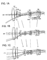
- Figs.1A to 1C shows construction of a zoom lens according to a Working Example 1 of the present invention, and shows trajectory of each lens group when the focal length of the zoom lens changes from the wide-angle end(W) to the telephoto end(T) by way of the intermediate state(M).
- Working Example 1 is suitable for use with electronic imaging equipment requiring a zoom lens set at infinite focus.
- a first lens group G1 comprises, in order from object side, a cemented positive lens comprising a negative meniscus lens having a convex surface facing to the object side and a double convex lens, and a positive meniscus lens having a convex surface facing to the object.
- a second lens group G2 comprises a double concave lens having an aspherical surface facing to the object.
- a third lens group G3 comprises, in order from object side, a cemented negative lens comprising a double concave lens and a positive meniscus lens having a convex surface facing to the object side.
- a fourth lens group G4 comprises, in order from object side, a double convex lens and a negative meniscus lens having a concave surface facing to the object side.
- a fifth lens group G5 comprises, in order from object side, a double convex lens having an aspherical surface facing to the image side and a cemented positive lens comprising a double convex lens and a negative meniscus lens having a concave surface facing to the object side.
- the second lens group G2, the third lens group G3, and the fifth lens group G5 move along the trajectories shown by the arrows in Figs.1A to 1C.
- the first lens group G1 and the fourth lens group G4 are fixed.
- an aperture diaphragm S is arranged in the vicinity of the fourth lens group G4 between the third lens group G3 and the fourth lens group G4. The aperture diaphragm S is fixed when zooming, as well as the fourth lens group G4.
- a vibration reduction lens group G4v consisting of the fourth lens group G4 shifts in a direction substantially perpendicular to the optical axis, thereby correcting an image fluctuation caused by a camera shake.
- Table 1 shows the specification values of Working Example 1 of the present invention.
- the reference symbol f denotes the focal length of the entire zoom lens
- FNO denotes f-number
- Bf denotes the back focal length
- D0 denotes a distance along the optical axis between an object and the surface of the optical system which is closest to the object.
- the reference symbol R denotes the radius of curvature, and when a surface is aspherical surface, R denotes the vertex radius of curvature.
- the reference symbols ⁇ W, ⁇ M, and ⁇ T denote maximum displacement amounts ⁇ 4 of the vibration reduction lens group G4v at the wide-angle end, in the medium focal length state, and at the telephoto end, respectively.
- the sign of ⁇ 4 is same as that of ⁇ W, ⁇ M, or ⁇ T
- the displacement direction of the vibration reduction lens group G4v is same as the moving direction of the image.
- the sign of ⁇ 4 is different from that of ⁇ W, ⁇ M, or ⁇ T
- the displacement direction of the vibration reduction lens group G4v is opposite to the moving direction of the image.
- the reference symbol fm denotes the focal length of the zoom lens in the intermediate focal length state.
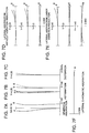
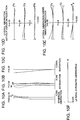
- Figs. 2A through 2F are graphs showing aberrations at the wide-angle end focused on an infinite object.
- Figs. 3A through 3F are graphs showing aberrations in the intermediate state focused on an infinite object.
- Figs. 4A through 4F are graphs showing aberrations at the telephoto end focused on an infinite object.
- FNO denotes f-number
- Y denotes image height
- a solid curve represents the sagittal image plane
- a broken curve represents the meridional image plane.
- Figs.5A to 5C shows construction of a zoom lens according to a Working Example 2 of the present invention, and shows trajectory of each lens group when the focal length of the zoom lens changes from the wide-angle(W) end to the telephoto end(T) by way of the intermediate state(M).
- Working Example 2 is suitable for use with electronic imaging equipment requiring a zoom lens set at finite focus.
- a first lens group G1 comprises, in order from the object side, a cemented positive lens comprising a negative meniscus lens having a convex surface facing to the object and a double convex lens, and a positive meniscus lens having a convex surface facing to the object side;
- a second lens group G2 comprises a negative meniscus lens having a convex surface facing to the object side;
- a third lens group G3 comprises, in order from object side, a cemented negative lens comprising a double concave lens and a positive meniscus lens having a convex surface facing to the object side;
- a fourth lens group G4 comprises, in order from object side, a cemented positive lens comprising a double convex lens and a negative meniscus lens having a concave surface facing to the object side;
- a fifth lens group comprises, in order from object side, a double convex lens and a cemented positive lens comprising a double convex
- the second lens group G2, the third lens group G3, and the fifth lens group G5 move along the trajectories shown by the arrow in Figs.5A to 5C.
- the first lens group G1 and the fourth lens group G4 are fixed.
- an aperture diaphragm S is arranged in the vicinity of the fourth lens group G4 between the third lens group G3 and the fourth lens group G4. The aperture diaphragm S is fixed when zooming, as well as the fourth lens group G4.
- a vibration reduction lens group G4v consisting of the fourth lens group G4 shifts in a direction substantially perpendicular to the optical axis, thereby correcting an image fluctuation caused by a camera shake.
- Table 2 shows the specification values of Working Example 2 of the present invention.
- ⁇ denotes the photographing magnification
- NA denotes the numerical aperture
- Bf denotes the back focal length
- D0 denotes a distance along the optical axis between an object and the surface of the optical system which is closest to the object.
- SNO denotes the lens surface number in order from the object side (i.e., along the direction in which the light rays travel)
- D denotes the interval between the surfaces
- R denotes the radius of curvature, and when a surface is aspherical surface, R denotes the vertex radius of curvature.
- the reference symbols ⁇ W, ⁇ M, and ⁇ T denote maximum displacement amounts ⁇ 4 of the vibration reduction lens group G4v at the wide-angle end, in the intermediate focal length state, and at the telephoto end, respectively.
- the sign of ⁇ 4 is same as that of ⁇ W, ⁇ M, or ⁇ T
- the displacement direction of the vibration reduction lens group G4v is same as the moving direction of the image.
- the sign of ⁇ 4 is different from that of ⁇ W, ⁇ M, or ⁇ T
- the displacement direction of the vibration reduction lens group G4v is opposite to the moving direction of the image.
- the reference symbol ⁇ w, ⁇ m, and ⁇ t denote the photographing magnification at the wide-angle end, in the intermediate focal length state, and at the telephoto end, respectively.
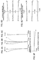
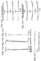
- Figs. 6A through 6F are graphs showing aberrations at the wide-angle end focused on a finite object.
- Figs. 7A through 7F are graphs showing aberrations in the intermediate state focused on a finite object.
- Figs. 8A through 8F are graphs showing aberrations at the telephoto end focused on a finite object.
- NA denotes the numerical aperture
- Y denotes image height
- a solid curve represents the sagittal image plane
- a broken curve represents the meridional image plane.
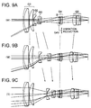
- Figs.9A to 9C shows construction of a zoom lens according to a Working Example 3 of the present invention, and shows trajectory of each lens group when the focal length of the zoom lens changes from the wide-angle end(W) to the telephoto end(T) by way of the intermediate state(M).
- Working Example 3 same as Working Example 1, is suitable for use with electronic imaging equipment requiring a zoom lens set at infinite focus.
- a zoom lens showing in Figs. 9A to 9C is constituted by, in the following order.
- a first lens group G1 comprises, in order from the object side, a cemented positive lens comprising a negative meniscus lens having a convex surface facing to the object and a double convex lens, and a positive meniscus lens having a convex surface facing to the object side.
- a second lens group G2 comprises a double concave lens having an aspherical surface facing to the object side.
- a third lens group G3 comprises, in order from object side, a cemented negative lens comprising a double concave lens and a positive meniscus lens having a convex surface facing to the object side.
- a fourth lens group G4 comprises, in order from object side, a cemented positive lens comprising a double convex lens and a negative meniscus lens having a concave surface facing to the object side and a negative meniscus lens having a concave surface facing to the object side.
- a fifth lens group comprises, in order from object side, a double convex lens having an aspherical surface facing to the image side and a cemented positive lens comprising a double convex lens and a negative meniscus lens having a concave surface facing to the object side.
- the second lens group G2, the third lens group G3, and the fifth lens group G5 move along the trajectories shown by the arrow in Figs.9A to 9C.
- the first lens group G1 and the fourth lens group G4 are fixed.
- an aperture diaphragm S is arranged in the vicinity of the fourth lens group G4 between the third lens group G3 and the fourth lens group G4. The aperture diaphragm S is fixed when zooming, as well as the fourth lens group G4.
- a vibration reduction lens group G4v consisting of a cemented positive lens, which is a portion of the fourth lens group G4, shifts in a direction substantially perpendicular to the optical axis, thereby correcting an image fluctuation caused by a camera shake.
- Table 3 shows the specification values of Working Example 3 of the present invention.
- the reference symbol f denotes the focal length of the entire zoom lens
- FNO denotes f-number
- Bf denotes the back focal length
- D0 denotes a distance along the optical axis between an object and the surface of the optical system which is closest to the object.
- the reference symbol SNO denotes the lens surface number in order from the object side (i.e., along the direction in which the light rays travel)
- D denotes the interval between the surfaces
- the reference symbol R denotes the radius of curvature, and when a surface is aspherical surface, R denotes the vertex radius of curvature.
- the reference symbols ⁇ W, ⁇ M, and ⁇ T denote maximum displacement amounts ⁇ 4 of the vibration reduction lens group G4v at the wide-angle end, in the intermediate focal length state, and at the telephoto end, respectively.
- the sign of ⁇ 4 is same as that of ⁇ W, ⁇ M, or ⁇ T
- the displacement direction of the vibration reduction lens group G4v is same as the moving direction of the image.
- the sign of ⁇ 4 is different from that of ⁇ W, ⁇ M, or ⁇ T
- the displacement direction of the vibration reduction lens group G4v is opposite to the moving direction of the image.
- the reference symbol fm denotes the focal length of the zoom lens in the intermediate focal length state.
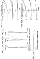
- Figs. 10A through 10F are graphs showing aberrations at the wide-angle end focused on an infinite object.
- Figs. 11A through 11F are graphs showing aberrations in the intermediate state focused on an infinite object.
- Figs. 12A through 12F are graphs showing aberrations at the telephoto end focused on an infinite object.
- FNO denotes f-number
- Y denotes image height
- a solid curve represents the sagittal image plane
- a broken curve represents the meridional image plane.
- the first lens group G1 and the fourth lens group G4 are fixed when zooming.
- the number of degrees of freedom of aberration correction increases, making it easier to design a zoom lens that performs the effect of the present invention.
- the present invention is a high-performance zoom lens having a long back focal length, and superior imaging performance even in the intermediate focal length state. Satisfactory imaging performance can be achieved at infinite focus or then focusing on a short-distance object even under vibration correction. Accordingly, the zoom lens of the present invention is ideally suited for use with electronic imaging equipment, such as video cameras, digital still cameras, and the like.
Landscapes
- Physics & Mathematics (AREA)
- General Physics & Mathematics (AREA)
- Optics & Photonics (AREA)
- Lenses (AREA)
- Adjustment Of Camera Lenses (AREA)
Applications Claiming Priority (2)
| Application Number | Priority Date | Filing Date | Title |
|---|---|---|---|
| JP01808699A JP4356040B2 (ja) | 1999-01-27 | 1999-01-27 | 防振機能を備えたバックフォーカスの長いズームレンズ |
| JP1808699 | 1999-01-27 |
Publications (2)
| Publication Number | Publication Date |
|---|---|
| EP1024387A2 true EP1024387A2 (de) | 2000-08-02 |
| EP1024387A3 EP1024387A3 (de) | 2002-05-08 |
Family
ID=11961848
Family Applications (1)
| Application Number | Title | Priority Date | Filing Date |
|---|---|---|---|
| EP00300570A Withdrawn EP1024387A3 (de) | 1999-01-27 | 2000-01-26 | Zoomobjektiv mit grossem Brennpunktsabstand von der Linsenrückseite und Funktion zur Reduktion von Vibrationen |
Country Status (3)
| Country | Link |
|---|---|
| US (1) | US6285501B1 (de) |
| EP (1) | EP1024387A3 (de) |
| JP (1) | JP4356040B2 (de) |
Cited By (2)
| Publication number | Priority date | Publication date | Assignee | Title |
|---|---|---|---|---|
| CN103293645A (zh) * | 2012-02-29 | 2013-09-11 | 株式会社理光 | 变焦镜头、成像设备以及便携数字设备 |
| CN113759500A (zh) * | 2020-06-05 | 2021-12-07 | 浙江舜宇光学有限公司 | 一种光学成像镜头 |
Families Citing this family (20)
| Publication number | Priority date | Publication date | Assignee | Title |
|---|---|---|---|---|
| JP3656089B2 (ja) * | 2000-03-29 | 2005-06-02 | コニカミノルタフォトイメージング株式会社 | 撮像レンズ装置 |
| US6560016B2 (en) * | 2000-03-31 | 2003-05-06 | Canon Kabushiki Kaisha | Zoom lens and photographing apparatus using the same |
| JP3524482B2 (ja) * | 2000-09-26 | 2004-05-10 | キヤノン株式会社 | ズームレンズ及びそれを用いた光学機器 |
| JP3943886B2 (ja) | 2001-10-04 | 2007-07-11 | キヤノン株式会社 | テーブル作成方法、テーブル作成装置、記憶媒体及びプログラム |
| US6813089B2 (en) * | 2002-02-07 | 2004-11-02 | Fuji Photo Optical Co., Ltd. | Extender optical system |
| JP4284641B2 (ja) * | 2002-12-27 | 2009-06-24 | 株式会社ニコン | ズームレンズ |
| JP4587028B2 (ja) * | 2004-07-08 | 2010-11-24 | ソニー株式会社 | ズームレンズ |
| JP4221670B2 (ja) * | 2004-09-30 | 2009-02-12 | ソニー株式会社 | ズームレンズ及び撮像装置 |
| US20080018988A1 (en) * | 2006-07-24 | 2008-01-24 | Andrew Davidson | Light source with tailored output spectrum |
| US9304305B1 (en) * | 2008-04-30 | 2016-04-05 | Arete Associates | Electrooptical sensor technology with actively controllable optics, for imaging |
| JP5530105B2 (ja) * | 2009-01-30 | 2014-06-25 | パナソニック株式会社 | ズームレンズ系、交換レンズ装置、及びカメラシステム |
| JP5416980B2 (ja) * | 2009-01-30 | 2014-02-12 | パナソニック株式会社 | ズームレンズ系、交換レンズ装置、及びカメラシステム |
| JP5668544B2 (ja) * | 2011-03-15 | 2015-02-12 | 株式会社リコー | ズームレンズおよびカメラおよび情報装置 |
| US9172856B2 (en) | 2011-03-29 | 2015-10-27 | Microsoft Technology Licensing, Llc | Folded imaging path camera |
| JP6210208B2 (ja) | 2012-12-27 | 2017-10-11 | パナソニックIpマネジメント株式会社 | インナーフォーカスレンズ系、交換レンズ装置及びカメラシステム |
| JP6253012B2 (ja) | 2012-12-27 | 2017-12-27 | パナソニックIpマネジメント株式会社 | インナーフォーカスレンズ系、交換レンズ装置及びカメラシステム |
| JP6300070B2 (ja) | 2013-02-22 | 2018-03-28 | パナソニックIpマネジメント株式会社 | ズームレンズ系、交換レンズ装置及びカメラシステム |
| US9470881B2 (en) * | 2013-10-25 | 2016-10-18 | Ricoh Company, Ltd. | Zoom lens and imaging device using zoom lens |
| JP6729717B2 (ja) | 2016-11-21 | 2020-07-22 | 株式会社ニコン | 変倍光学系、これを用いた光学機器および撮像機器 |
| CN112684596B (zh) * | 2021-01-05 | 2022-08-09 | 沈阳中一光学科技有限公司 | 有效焦距17mm、相对孔径F=0.95数码微单相机超大光圈M4/3画幅镜头 |
Family Cites Families (7)
| Publication number | Priority date | Publication date | Assignee | Title |
|---|---|---|---|---|
| JP3359131B2 (ja) * | 1993-11-04 | 2002-12-24 | キヤノン株式会社 | 防振機能を有した変倍光学系 |
| JPH07199124A (ja) | 1993-12-28 | 1995-08-04 | Nikon Corp | 防振機能を備えたズームレンズ |
| US5841588A (en) * | 1996-03-06 | 1998-11-24 | Nikon Corporation | Zoom lens system with vibration reduction means |
| JP3716418B2 (ja) * | 1996-08-01 | 2005-11-16 | 株式会社ニコン | 変倍光学系 |
| JP3849129B2 (ja) | 1997-08-18 | 2006-11-22 | 株式会社ニコン | ズームレンズ |
| US6002527A (en) * | 1998-02-11 | 1999-12-14 | Nikon Corporation | Compact high-zoom-ratio zoom lens |
| JPH11258504A (ja) * | 1998-03-12 | 1999-09-24 | Nikon Corp | 防振ズームレンズ |
-
1999
- 1999-01-27 JP JP01808699A patent/JP4356040B2/ja not_active Expired - Lifetime
-
2000
- 2000-01-26 EP EP00300570A patent/EP1024387A3/de not_active Withdrawn
- 2000-01-27 US US09/492,179 patent/US6285501B1/en not_active Expired - Lifetime
Cited By (4)
| Publication number | Priority date | Publication date | Assignee | Title |
|---|---|---|---|---|
| CN103293645A (zh) * | 2012-02-29 | 2013-09-11 | 株式会社理光 | 变焦镜头、成像设备以及便携数字设备 |
| CN103293645B (zh) * | 2012-02-29 | 2016-02-10 | 株式会社理光 | 变焦镜头、成像设备以及便携数字设备 |
| CN113759500A (zh) * | 2020-06-05 | 2021-12-07 | 浙江舜宇光学有限公司 | 一种光学成像镜头 |
| CN113759500B (zh) * | 2020-06-05 | 2022-09-09 | 浙江舜宇光学有限公司 | 一种光学成像镜头 |
Also Published As
| Publication number | Publication date |
|---|---|
| JP4356040B2 (ja) | 2009-11-04 |
| US6285501B1 (en) | 2001-09-04 |
| JP2000214386A (ja) | 2000-08-04 |
| EP1024387A3 (de) | 2002-05-08 |
Similar Documents
| Publication | Publication Date | Title |
|---|---|---|
| US6285501B1 (en) | Zoom lens having a long back focal length with vibration reduction function | |
| JP3606548B2 (ja) | 3群ズームレンズ | |
| JP4111470B2 (ja) | 広角ズームレンズ | |
| JPH05173071A (ja) | 広角ズームレンズ | |
| EP2075614A2 (de) | Zoomobjektiv | |
| JP2012093548A (ja) | 変倍光学系、この変倍光学系を有する光学機器、及び、変倍光学系の製造方法 | |
| JP3849129B2 (ja) | ズームレンズ | |
| JP2012027309A (ja) | ズームレンズ、光学装置、ズームレンズの製造方法 | |
| JP4591780B2 (ja) | 可変焦点距離レンズ系及び撮像装置 | |
| JPH08122640A (ja) | ズームレンズ | |
| JP6164894B2 (ja) | ズームレンズ及びそれを有する撮像装置 | |
| JPH1048524A (ja) | 変倍光学系 | |
| CN115004074B (zh) | 变倍光学系统以及光学设备 | |
| JPH095626A (ja) | 変倍光学系 | |
| JP4972900B2 (ja) | ズームレンズ | |
| JPH0727979A (ja) | ズームレンズ | |
| EP1967882B1 (de) | Zoomteleobjektiv mit vier Linsengruppen | |
| JP4674567B2 (ja) | ズームレンズとこれを具備する光学装置 | |
| JPH10268195A (ja) | 近距離合焦可能な変倍光学系 | |
| JP2007298832A (ja) | ズームレンズとこれを具備する光学装置。 | |
| JP4379957B2 (ja) | リアフォーカス式ズームレンズ及びそれを用いた光学機器 | |
| JP4333151B2 (ja) | ズームレンズ | |
| JP4951915B2 (ja) | ズームレンズ | |
| JPH1062688A (ja) | 変倍光学系 | |
| JP5505770B2 (ja) | ズームレンズ、光学機器 |
Legal Events
| Date | Code | Title | Description |
|---|---|---|---|
| PUAI | Public reference made under article 153(3) epc to a published international application that has entered the european phase |
Free format text: ORIGINAL CODE: 0009012 |
|
| AK | Designated contracting states |
Kind code of ref document: A2 Designated state(s): AT BE CH CY DE DK ES FI FR GB GR IE IT LI LU MC NL PT SE |
|
| AX | Request for extension of the european patent |
Free format text: AL;LT;LV;MK;RO;SI |
|
| PUAL | Search report despatched |
Free format text: ORIGINAL CODE: 0009013 |
|
| AK | Designated contracting states |
Kind code of ref document: A3 Designated state(s): AT BE CH CY DE DK ES FI FR GB GR IE IT LI LU MC NL PT SE |
|
| AX | Request for extension of the european patent |
Free format text: AL;LT;LV;MK;RO;SI |
|
| AKX | Designation fees paid | ||
| REG | Reference to a national code |
Ref country code: DE Ref legal event code: 8566 |
|
| STAA | Information on the status of an ep patent application or granted ep patent |
Free format text: STATUS: THE APPLICATION IS DEEMED TO BE WITHDRAWN |
|
| 18D | Application deemed to be withdrawn |
Effective date: 20021109 |