EP1009870B2 - Reguliertes streckwerk - Google Patents
Reguliertes streckwerk Download PDFInfo
- Publication number
- EP1009870B2 EP1009870B2 EP98938866A EP98938866A EP1009870B2 EP 1009870 B2 EP1009870 B2 EP 1009870B2 EP 98938866 A EP98938866 A EP 98938866A EP 98938866 A EP98938866 A EP 98938866A EP 1009870 B2 EP1009870 B2 EP 1009870B2
- Authority
- EP
- European Patent Office
- Prior art keywords
- sliver
- speed
- drafting
- drafting device
- card
- Prior art date
- Legal status (The legal status is an assumption and is not a legal conclusion. Google has not performed a legal analysis and makes no representation as to the accuracy of the status listed.)
- Expired - Lifetime
Links
Images


Classifications
-
- D—TEXTILES; PAPER
- D01—NATURAL OR MAN-MADE THREADS OR FIBRES; SPINNING
- D01G—PRELIMINARY TREATMENT OF FIBRES, e.g. FOR SPINNING
- D01G15/00—Carding machines or accessories; Card clothing; Burr-crushing or removing arrangements associated with carding or other preliminary-treatment machines
- D01G15/02—Carding machines
- D01G15/12—Details
- D01G15/46—Doffing or like arrangements for removing fibres from carding elements; Web-dividing apparatus; Condensers
- D01G15/64—Drafting or twisting apparatus associated with doffing arrangements or with web-dividing apparatus
-
- D—TEXTILES; PAPER
- D01—NATURAL OR MAN-MADE THREADS OR FIBRES; SPINNING
- D01G—PRELIMINARY TREATMENT OF FIBRES, e.g. FOR SPINNING
- D01G23/00—Feeding fibres to machines; Conveying fibres between machines
- D01G23/06—Arrangements in which a machine or apparatus is regulated in response to changes in the volume or weight of fibres fed, e.g. piano motions
-
- D—TEXTILES; PAPER
- D01—NATURAL OR MAN-MADE THREADS OR FIBRES; SPINNING
- D01G—PRELIMINARY TREATMENT OF FIBRES, e.g. FOR SPINNING
- D01G31/00—Warning or safety devices, e.g. automatic fault detectors, stop motions
- D01G31/006—On-line measurement and recording of process and product parameters
Definitions
- the invention relates to a drafting system, wherein the drafting device is preceded by a carding machine with a fiber-band-forming device for producing a sliver, which is the drafting system, which is arranged downstream of a tape storage.
- the draft of the drafting system is so high that thereby significantly increases the degree of fiber orientation in the band or the proportion of hook fibers is substantially reduced, wherein the sliver forming means for producing a sliver with a band thickness higher than 8 ktex, for example 10 to 12 ktex, and wherein the drafting system can produce a total draft of more than 2, preferably more than 3 and for example 3 to 6.
- the drafting unit is followed by a belt deposit and the draft of the drafting unit is so high that it is ensured that the degree of fiber orientation in the formed sliver substantially increased or the proportion of hook fibers is substantially reduced.
- Information about stretching prior to depositing can be found in the book "Abridged cotton mill - Prof. Dr. Ing. Walther Wegener - Mönchengladbach 1965". This will be discussed in more detail below.
- the delay is greater than 2, preferably between 3 and 6. This should additionally ensure that a sliver is formed with a high-quality fiber structure, which has a positive effect especially in subsequent processing stages.
- the belt-forming device In order to allow such a high distortion between the belt-forming device and the belt storage, the belt-forming device according to the invention produces a sliver having a relatively low fineness (high strength), for example at least 8 ktex and preferably 10 ktex or even more (for example 12 ktex).
- the card is preferably used with a relatively high working width, for example greater than 1200 mm. This can be done with a machine according to the EP Patent Application No. 866153 will be realized.
- the overall content of the mentioned EP application is hereby incorporated by reference as an integral part of the present description.
- the strip fineness after the drafting device can be, for example, 3 to 5 ktex.
- the delivery speed at the exit of the drafting system is for example more than 400 m / min.
- such drafting is provided on the tape tray (see the textbook "Shortened cotton mill", page 72 and the mentioned therein CS patent 98,939 ), so that the sliver supplied by the drafting system as quickly as possible (without having to go through a long transport path) can be stored.
- the drafting system is associated with at least one means which is suitable to detect a necessary control intervention in the drafting device drive to maintain a predetermined setpoint before or during the control intervention and to use to influence the basic speed of the drafting system.
- any memory required between the textile-processing machine and the following regulating drafting system can be kept relatively small, since the regulating interventions are compensated by the tracking of the basic speed of the drafting system.
- the further means is suitable for detecting differences between the delivery speed of the source and the entry speed into the drafting system.
- the difference in speed is due to the change in the speed of the regulated drafting roller.
- the further means may be suitable for detecting long-term mass fluctuations with respect to a predetermined desired value.
- the further means is a sliver storage, which may be equipped with corresponding monitoring elements or sensors.
- the differences in the conveying speed of the sliver which arise due to the variable and regulated withdrawal speed of the pair of input rollers of the drafting unit, can be recognized by the variable level of the memory and can be made an intervention in the basic speed of the drafting system. This pre-control is made, which ensures that the memory can be kept at a low level.
- the sliver storage can be designed as a slack storage, the slack of the sliver loop can be continuous or discontinuous.
- an additional sensor for detecting the fiber mass is provided, which can be arranged directly after the outlet of a drafting unit upstream textile material processing unit. This makes it possible to detect long-term mass deviations very early and to react with a corresponding intervention in the basic speed of the following drafting system.
- the textile processing unit is a card, wherein the sensor attached to the outlet of the carding machine can be used at the same time for long-term regulation of the feed device of the card.
- the further means may also consist of a sensor device for sensing the rotational speed of the regulated pair of rollers of the drafting system and at least one of the drafting upstream and constantly revolving conveyor roller pair for the fiber mass, via the determined speed ratio, the long-term mass deviation is determined and resulting therefrom intervention in the basic speed of the Drafting be made.
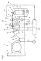
- Fig. 1 schematically shows the representation of a carding machine 1, which is fed via a feed chute 3 and via a subsequent feed roller 2 with fiber material.
- the fiber material is taken up by the spool and processed in cooperation with Kardierettin not shown.
- the carded Material is removed by a doffer roller 5 from the drum 4 and transferred to a schematically indicated extraction device 10.
- the sliver 6 formed there passes in the conveying direction F to a slack store 14, which is equipped with pairs of input rollers 15 and 16 pairs of output rollers.
- the slack (sliver loop FS) is scanned by a beam sensor 20, which is provided with sensors arranged in series one above the other. This makes it possible to detect each position of the sliver loop FS exactly.
- the sensor signals are output via the line 21 to a control unit S.
- the output from the memory 14 sliver 6 is guided by a measuring member 70, which is designed in the form of a Tastwalzenploes.
- the measurement result of the measuring member 70 is delivered via the line 71 to the control unit S. Subsequent to the measuring member 70, the sliver is guided into the drafting unit 30 with the roller pairs 24 and 25, in which it is warped.
- the basic drive of the drafting unit 30 takes place from the motor M2, which is controlled by the control unit S via the line 40.
- the motor M1 of the pickup roller 5 is in this case designed as a master motor (master), the motor M2 is tracked in its basic speed as a "slave" to comply with predetermined drive ratios. This base speed of the motor M2 can be overridden by the signals of the sensor 20, which will be discussed in more detail below.
- the motor M2 drives a gear 32, from which a drive path 35 leads to the output rollers 25 and another drive path 36 to a control gear 33 (differential). From this control gear 33 is via the drive path 37, the input roller pair 24 of the drafting unit 30 driven.
- the control interventions which are necessary by evaluating the signals of the measuring member 70 based on a predetermined setpoint for balancing mass fluctuations (short and long wave), made by a control motor M3, which is controlled by the control unit S via the line 38 and regulating in the Regulator 33 engages.
- a control motor M3 which is controlled by the control unit S via the line 38 and regulating in the Regulator 33 engages.
- the delay between the roller pairs 24 and 25 is changed and compensated for mass fluctuations in the sliver.
- card sliver here means a sliver, which is delivered to one of the card subsequent band storage.
- a real Japanese release JP OS 51-2 from the year 1976; User Fuji Seiko KK describes a drafting system on the carding machine with a yielding capacity of 1.1 to 2 times.
- the invention provides a drafting device for use between the belt-forming device and the tape storage of a carding machine, wherein the drafting system can generate such a high distortion that thereby significantly increases the degree of fiber orientation in the belt or the proportion of hook fibers is substantially reduced.
- the stretching of the fiber sliver preceding the depositing can be used to significantly reduce the proportion of towing hooks (see the textbook “Shortened Spinning", page 90).
- the sliver is subjected to a distortion of more than 2 and preferably more than 3. If possible, a delay of 5 to 6 should be used, but this can rarely be achieved between the card runout and the subsequent tape storage without disturbing the running behavior of the sliver.
- the belt-forming device according to the invention produces a sliver having a relatively low fineness (high gauge) of at least 8 ktex and preferably 10 ktex or even more (eg 12 ktex).
- a relatively high working width of the card for example greater than 1200 mm. This can be done with a machine according to the EP patent application No. 98 810 088.9 will be realized.
- the overall content of the mentioned EP application is hereby incorporated by reference as an integral part of the present description.
- the EP application was published on 23.09.1998 under the number 866 153.
- the belt fineness after the drafting system can be eg 3 to 5 ktex.
- the delivery speed at the exit of the drafting system is for example more than 400 m / min.
- such drafting is provided on the tape tray (see the textbook "Abridged cotton mill, page 72 and the therein mentioned CS patent 98,939 ), so that the sliver supplied by the drafting system as quickly as possible (without having to go through a long transport path) can be stored.
- a carded web is combined to form a sliver and that the band is drawn with a delay of at least 2, and preferably more than 3, prior to depositing.
- a card is provided with a sliver-forming device, a sliver tray and a drafting device connected between the sliver-forming device and the sliver depositing device, wherein the drafting device is designed to generate a warpage greater than 2 and preferably higher than 3.
- the drafting system can be formed as a homogenizing unit, ie it can be arranged to produce a controllable variable distortion, but this is not essential to the invention. Delay changes will lead to corresponding changes in the degree of orientation.
- the card itself can therefore be conveniently designed as a homogenization unit (eg EP-A-271 115 ), wherein the subsequent drafting system is designed to increase the degree of fiber orientation.
- a controlled drafting system has a total draft GV (between the infeed and outfeed roller pairs) of more than 2 and preferably 3 to 6. If the drafting system has a pre-drafting zone, which is not essential to the invention, the mean distortion in the controlled (variable) drafting zone can be adjusted, for example. 2.5, the warping in the other (fixed) drafting zone e.g. about 1.2.
- the "Vorverzug" (in the first
- Default field may e.g. 1.1 to 1.5 and the "main delay" (in the second, variable default field) amount to about 2.0 to 4.
- the sliver thickness at the outlet of the drafting system is preferably 3 to 5 ktex, for example 3.5 ktex.
- the drafting arrangement is preferably arranged directly above the funnel wheel of a belt deposit, for example as shown in DE-Gbm-296 22 923.
- the sliver deposited in the pot can directly to the OE spinning machine, for example, after EP-A-627 509 to be delivered.
- the invention is preferably (but not necessarily) used in combination with the other features of the invention described in the introduction.
- a monitoring member 44 is still arranged, which is connected via the line 45 to the control unit S. This serves for the final monitoring of the number of the sliver formed and switches off the machine if the number is outside a certain tolerance range for a predetermined period of time.
- the sliver is deposited on the calender rolls 47 and the funnel wheel 48 in a can K in loop form, the can K is rotated during the depositing operation on the can plate 49.
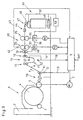
- a device wherein following the discharge device 10, a pair of measuring rollers 55 is arranged, which is connected via the line 56 to the control unit S.
- This measuring element 55 detects substantially the long-term mass fluctuations (drifting the number of the sliver). According to the signal of this measuring member 55 in comparison with a predetermined setpoint, a control signal is generated in the control device, which is used to override the basic speed of the motor M2. This can be reacted early on a subsequent control intervention in the drafting system 30 to keep the memory at a constant level of sliver loop.
- the memory 14 is in this case only provided with two sensors S1 and S2, which only respond when the sliver loop FS moves outside a predetermined tolerance range. As a rule, there is a fault and the machine (system) is switched off.
- the signal of the measuring member 55 is used in addition to the regulation of the drive motor MS of the feed roller of the card 1 to the drift of the number already at the card.
- the motor MS is controlled by the control unit via line 53.
- Fig. 3 shows a further embodiment, wherein a pair of delivery rollers 11 is arranged downstream of the trigger device 10. The speed of this pair of rollers is monitored by a sensor 12. Likewise, in this case the feed roller pair 24 of the drafting system 30, a speed sensor 62 associated with which is connected via the line 63 to the control unit S.
- the execution of the memory 14 corresponds to the embodiment, which already in the embodiment of FIG. 2 has been described.
- the measured speed ratio between the mentioned roller pairs (11, 24) remains constant.
- a control intervention takes place, as a result of which the rotational speed of the input rollers 24 changes.
- This also changes the speed ratio between the roller pairs 11 and 24, which is generated according to the change, a control signal from the control unit S, the base speed of the drafting 30 and the motor M2 changes or overrides, as in the example of Fig. 2 described to compensate for the control intervention.
- the compensation of the control intervention on the override of the basic speed of the drafting system 30 refers only to the long-term mass fluctuations and not to the short-term, since these fluctuations are not significant and usually compensate themselves over time.
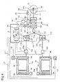
- Fig. 4 an embodiment is shown, wherein two cards 1a, 1b work side by side in parallel.
- the cards are also provided with feed rollers 6a, 6b, briseur 3a, 3b, tambour 2a, 2b and take-off roller 4a, 4b.
- the drive of the pickup rollers 4a and 4b is schematically indicated by 75 and 46, which are connected via a control line L8 and L9 to the control unit S.
- the drive 20a or 20b of the feed rollers 6a and 6b is also connected via the control lines L7 'and L7 "to the control unit S.
- control unit S and the respective control lines L8 and L9 ensures that the rotational speeds of the pickup rollers 4a and 4b are coordinated, that is, the drive 46 of the pickup roller 4b is tracked as a "slave” the drive 75 of the pickup roller 4a, which acts as a "master”.
- the fiber slivers Fa and Fb emitted by the respective card 1a or 1b are guided by a respective sensor 10a or 10b in order to scan their mass. Subsequently, the slivers Fa and Fb each pass into a slack memory 11a and 11b.
- sensors O1, U1 and O2, U2 are mounted for scanning the fill level or the slack of the sliver loops.
- the sensors O1, O2 scan an upper position and the sensors U1, U2 a lower position of the sliver loop. Between the respective upper sensor and the lower sensor is the tolerance limit within which the sliver loop can move freely, without triggering a control intervention. However, it would also be conceivable to provide a sensor with continuous scanning.
- the sensors O1, U1 and O2, U2 are connected via the lines L10 and L11 to the control unit S.
- the two slivers Fa and Fb are combined to form a single sliver FZ.
- This sliver FZ is then passed over a sensor 17, the sampling makes mass fluctuations in the submitted sliver FZ.
- the fiber sliver FZ scanned by the sensor 17 then passes into the regulating drafting system 83.
- the values determined by the sensor 17 are delivered to the control unit S via the line L3.
- the drafting system 83 consists in the example shown of three successively connected pairs of rollers 84, 85 and 86, wherein the pair of input rollers 84 is driven to adjust out of mass fluctuations in the sliver in the variable speed.
- the delivery roller pair 86 is driven by a main motor 65 and a subsequent gear 26 at a constant speed.
- the middle roller pair 85 is also driven at a constant speed and has a constant speed ratio to the subsequent delivery rollers 86. Due to the predetermined speed ratio, a constant distortion of the sliver between the roller pairs 85 and 86 is performed.
- the motor 85 is controlled by a frequency converter 84 and via the line L6 from the control unit S.
- a differential gear 28 is driven, which drives the input roller pair 84 via the drive train 31.
- the drive of the differential 28 can be overridden by a control motor 29, which is controlled via a frequency converter, not shown, and the line L5 via the control unit S. This override is based on the output from the sensor 17 signals that are compared with a stored in the control unit S actual value.
- a reel KA is arranged, in which the output from the drafting fiber sliver F1 via a Kalanderwalzencru 34 and a funnel T is placed in a pot K.
- the pot K stands on a driven can plate (not shown), which sets the pot K during the filling in rotation.
- the can plate, the calender rolls 34 and the funnel wheel T become driven by a gear 96 via the drive path 98.
- the transmission 96 is powered by the schematically shown fixed drive connection 95 of the transmission 26, which is driven by the main motor 65. It can be seen that the delivery roller pair 86 with the drive elements of the reel KA directly via the gear 26 is fixedly coupled together.
- a mixed signal MS is generated from the signals of the sensors 10a and 10b in the control unit S, which is compared with a setpoint value.
- the control signal SS resulting from this comparison is used to influence the set base speed of the motor 65.
- the basic speed of the drafting system is tuned or tracked to the speed of the take-off roll 4a. Only when the operating speed is reached is the override of the basic speed enabled.
- the fiber slivers Fa and Fb emitted by the cards 1a and 1b are detected by the sensors 10a and 10b and the corresponding actual values (mass) are output to the control unit, where a mixed signal MS is generated.
- This mixed signal is compared with a desired signal "desired” and used to generate a control signal if the actual value deviates from the nominal value.
- This control signal goes to a frequency converter 94, which changes the speed of the motor 65 via the line L6 and thus the basic speed of the drafting unit and also the tape tray KA.
- the slivers Fa and Fb are transferred to the slack stores 11a and 11b, in which they are scanned by the sensors O1, O2 and U1, U2. If the respective sliver loop is within the range between the upper and lower sensor, no additional control pulse is executed. However, for example, as soon as the sensor U2 indicates that the sliver loop of the sliver Fb is becoming too large, the direct tracking of the drive 46 of the doffer roll 4b from the drive 75, which is considered "master", is overridden and the speed of the roll 4b is reduced , As soon as the sliver loop moves back into the tolerance range between O2 and U2 after this intervention, the control coupling between the drives 65 and 46 is activated again. If the sliver loop does not return to the tolerance range after a predetermined time, there is a malfunction, which shuts down the entire system.
- the situation is similar with the monitoring in the memory 11a, wherein when the fiber sliver loop of the sliver Fa outside the tolerance range between the sensors U1 and O1 and over a predetermined time also the system is switched off, since a fault can be assumed.
- the fiber slivers leaving the respective store are brought together prior to entry into a subsequent measuring element 17 to form a common sliver FZ.
- the mass fluctuations are measured and delivered via the line L3 to the control unit S.
- a corresponding signal via the line L5 is delivered to the control motor 29, via the control gear 28, the speed of the input rollers 84 for balancing the mass variation changes.
- the delay between the roller pairs 84 and 85 changes.
- the delay between the roller pairs 85 and 86 remains constant.
- the thus warped sliver F1 is discharged from the drafting unit and stored on the calender rolls 34 and the funnel T in a can K looped.
- a drift of the mass m outside of a predetermined tolerance range To is detected at the time T1 via the sensors 10a, 10b. If now the drifting of the mass takes place at the time T1 without intervention in the base speed, the process would be as follows: Due to the lower mass submitted to the drafting system 83, the delay between the pairs of rollers 84 and 85 must be reduced. That is, via the control motor 29 and the differential 28, the speed of the input roller pair 84 is increased, whereby at the same time the delay between the roller pairs 84 and 85 is reduced, since the speed of the roller pair 85 remains constant. By reducing the speed of the input roller pair 84 and the feed rate of the delivered sliver F reduced.
- the original delivery speed of the sliver from the card remains the same.
- the resulting difference between the delivery speed of the card and the changed intake speed of the sliver at the drafting system 83 is collected by the sliver storage 11 a and 11b. That is, the excess supplied amount of sliver F fills the sliver storage 11a, 11b until again equal ratios between the discharge speed of the card and the drawing speed of the drafting are available. This compensation can then be brought about again as soon as the control engagement with the feed roller 6a, 6b produces its effect on the delivery to the card.
- this speed change of the roller 84 is approximately compensated, that is, the entire speed level of the drafting system 83 is shut down evenly by the driving relationship, so that despite changing the speed ratio between the roller pairs 84 and 85, the now existing The speed of the input roller pair is approximately at the same level that existed before the control intervention.
- the sensors U1, O1, U2, 02 serve as additional monitoring aid. For reasons of clarity was omitted in the curve of the roller 84 on the representation of the rashes, which are caused by the short-wave Ausregultechniken. These short-wave readjustments usually swing around the drawn curve up or down.
- the proposed device can be responded in good time to long-wave deviations in the sliver mass on the one hand with already known sensor devices and on the other hand, the need for the regulation at the entrance of the drafting system sliver storage are kept to a minimum.
Landscapes
- Engineering & Computer Science (AREA)
- Textile Engineering (AREA)
- Spinning Or Twisting Of Yarns (AREA)
- Preliminary Treatment Of Fibers (AREA)
Priority Applications (1)
| Application Number | Priority Date | Filing Date | Title |
|---|---|---|---|
| DE29825170U DE29825170U1 (de) | 1997-09-01 | 1998-08-31 | Reguliertes Streckwerk |
Applications Claiming Priority (7)
| Application Number | Priority Date | Filing Date | Title |
|---|---|---|---|
| DE1997138053 DE19738053A1 (de) | 1997-09-01 | 1997-09-01 | Karde mit Bandspeicher und Regulierstreckwerk |
| DE19738053 | 1997-09-01 | ||
| CH271197 | 1997-11-24 | ||
| CH271197 | 1997-11-24 | ||
| CH156098 | 1998-07-23 | ||
| CH156098 | 1998-07-23 | ||
| PCT/IB1998/001357 WO1999011847A1 (de) | 1997-09-01 | 1998-08-31 | Reguliertes streckwerk |
Publications (3)
| Publication Number | Publication Date |
|---|---|
| EP1009870A1 EP1009870A1 (de) | 2000-06-21 |
| EP1009870B1 EP1009870B1 (de) | 2002-07-03 |
| EP1009870B2 true EP1009870B2 (de) | 2008-09-17 |
Family
ID=27173074
Family Applications (1)
| Application Number | Title | Priority Date | Filing Date |
|---|---|---|---|
| EP98938866A Expired - Lifetime EP1009870B2 (de) | 1997-09-01 | 1998-08-31 | Reguliertes streckwerk |
Country Status (5)
| Country | Link |
|---|---|
| US (1) | US6286188B1 (tr) |
| EP (1) | EP1009870B2 (tr) |
| DE (1) | DE59804686D1 (tr) |
| TR (1) | TR200000962T2 (tr) |
| WO (1) | WO1999011847A1 (tr) |
Families Citing this family (16)
| Publication number | Priority date | Publication date | Assignee | Title |
|---|---|---|---|---|
| DE19923576A1 (de) * | 1999-05-21 | 2000-11-23 | Riebag Riesaer Beteiligungs Ag | Kämmmaschine mit mehreren Kämmköpfen |
| DE10023011B4 (de) * | 2000-05-11 | 2018-10-11 | Trützschler GmbH & Co Kommanditgesellschaft | Vorrichtung an einer Karde zur Verarbeitung von Fasermaterial, insbesondere Baumwolle, Chemiefasern u. dgl. |
| EP1205588B1 (de) * | 2000-11-08 | 2004-12-15 | Maschinenfabrik Rieter Ag | Steuerung von Spinnstellen in einer Spinnmaschine |
| DE10116944A1 (de) * | 2001-04-05 | 2002-10-10 | Truetzschler Gmbh & Co Kg | Vorrichtung an einer Karde zum Füllen einer Kanne mit länglichem Querschnitt |
| FR2825380B1 (fr) * | 2001-06-01 | 2003-08-15 | Schlumberger Cie N | Procede de controle de la qualite de fabrication de rubans de fibres textiles |
| US7103440B2 (en) * | 2001-12-11 | 2006-09-05 | Rieter Ingolstadt Spinnereimaschinenbau Ag | Use of microwaves for sensors in the spinning industry |
| DE10214955B9 (de) * | 2002-04-04 | 2017-06-29 | Rieter Ingolstadt Gmbh | Spinnereivorbereitungsmaschine |
| DE10227676A1 (de) * | 2002-06-20 | 2004-01-08 | Rieter Ingolstadt Spinnereimaschinenbau Ag | Verfahren und Vorrichtung zur Auswertung von Signalen eines Sensors |
| DE10327469B4 (de) * | 2002-07-06 | 2016-03-10 | Rieter Ingolstadt Gmbh | Bandquerschnittsmesseinrichtung |
| WO2004035888A1 (de) * | 2002-10-16 | 2004-04-29 | Rieter Ingolstadt Spinnereimaschinenbau Ag | Spinnereivorbereitungsmaschine sowie hohlraumresonator |
| DE10307603A1 (de) * | 2003-02-22 | 2004-09-02 | Rieter Ingolstadt Spinnereimaschinenbau Ag | Textilmaschine |
| DE102005006273A1 (de) * | 2004-04-21 | 2005-11-10 | Trützschler GmbH & Co KG | Vorrichtung zum Verfestigen eines förderbaren Faservlieses, z. B. aus Baumwolle, Chemiefasern o. dgl. |
| DE102013113308A1 (de) * | 2013-12-02 | 2015-06-03 | Rieter Ingolstadt Gmbh | Textilmaschine mit variablem Anspannverzug |
| CZ307263B6 (cs) * | 2016-11-21 | 2018-05-02 | Rieter Cz S.R.O. | Zařízení pro sledování průvěsu přástu před navíjecím zařízením přípravárenského stroje pro výrobu přástu |
| DE102017102623A1 (de) * | 2017-02-09 | 2018-08-09 | TRüTZSCHLER GMBH & CO. KG | Verfahren und Anlage zur Bearbeitung von Fasern |
| DE102022116504A1 (de) * | 2022-07-01 | 2024-01-04 | Maschinenfabrik Rieter Ag | Regulierstrecke, Verfahren zum Betreiben einer Regulierstrecke sowie Verfahren zum Umrüsten einer Regulierstrecke |
Citations (14)
| Publication number | Priority date | Publication date | Assignee | Title |
|---|---|---|---|---|
| DE1931929A1 (de) † | 1969-06-24 | 1971-02-11 | Zinser Textilmaschinen Gmbh | Vorrichtung zum Vergleichmaessigen von textilen Faserbaendern |
| DE2543839A1 (tr) † | 1975-10-01 | 1976-11-25 | ||
| DE2912576A1 (de) † | 1978-04-26 | 1979-10-31 | Zellweger Uster Ag | Verfahren und vorrichtung zur ausregulierung von bandgewichtsschwankungen an karden, krempeln, strecken u.dgl. |
| DE2912376A1 (de) † | 1979-03-29 | 1980-10-02 | Wella Ag | Verfahren und vorrichtung zur messung der rauchgastemperatur eines zentralheizungskessels |
| EP0038927A1 (de) † | 1980-03-28 | 1981-11-04 | Maschinenfabrik Rieter Ag | Verfahren und Vorrichtung zum Ausregulieren von Titerschwankungen eines Faserbandes |
| EP0446796A1 (de) † | 1990-03-16 | 1991-09-18 | Maschinenfabrik Rieter Ag | Ultra-Hochleistungskarde |
| DE4103525A1 (de) † | 1990-04-09 | 1991-10-10 | Truetzschler & Co | Vorrichtung zum verziehen von faserbaendern, z. b. aus baumwolle, chemiefaser u. dergl. |
| DE4424490A1 (de) † | 1994-07-12 | 1996-01-18 | Rieter Ingolstadt Spinnerei | Strecke und Verfahren zum Betrieb einer Strecke |
| EP0708849A1 (en) † | 1993-07-14 | 1996-05-01 | Carding Specialists (Canada) Limited | Carding/drafting leveller system |
| DE29622923U1 (de) † | 1996-06-29 | 1997-08-07 | Trützschler GmbH & Co KG, 41199 Mönchengladbach | Vorrichtung an einer Karde, bei der am Ausgang der Karde ein Flortrichter mit Abzugswalzen vorhanden ist |
| US5774942A (en) † | 1996-07-19 | 1998-07-07 | North Carolina State University | Feed-forward and feed-back autoleveling system for automated textile drafting system |
| US5774943A (en) † | 1996-07-19 | 1998-07-07 | North Carolina State University | Tongue and groove drafting roller autoleveling system for automated textile drafting system |
| US5774940A (en) † | 1996-07-19 | 1998-07-07 | North Carolina State University | Draftless sliver coiler packaging system for automated textile drafting system |
| WO1998032903A1 (de) † | 1997-01-23 | 1998-07-30 | Maschinenfabrik Rieter Ag | Karde mit streckwerk am auslauf |
Family Cites Families (40)
| Publication number | Priority date | Publication date | Assignee | Title |
|---|---|---|---|---|
| US3403426A (en) * | 1966-07-27 | 1968-10-01 | Maremont Corp | Textile sliver evening apparatus |
| DE1919929A1 (de) | 1969-04-19 | 1970-11-05 | Bosch Gmbh Robert | Einrichtung zum Erkennen des Schlupfs von Fahrzeugraedern |
| BE768780A (fr) | 1971-06-21 | 1971-11-03 | Texcontrol | Appareil textile destine a la regulation du titre a court, moyen et long termes des rubans de fibres en preparation de filature |
| JPS5129529A (ja) | 1974-09-02 | 1976-03-12 | Fuji Bellows Co Ltd | Ryumenki |
| ZA756783B (en) | 1974-11-07 | 1976-10-27 | Kollmorgen Corp | Method for cleaning holes in resincontaining materials |
| JPS51136601A (en) | 1975-07-07 | 1976-11-26 | Rikagaku Kenkyusho | Process for hydrogenation of organic nitro compounds |
| DE2941612A1 (de) * | 1979-10-13 | 1981-04-23 | Zinser Textilmaschinen Gmbh, 7333 Ebersbach | Strecke |
| JPS59187629A (ja) * | 1983-04-01 | 1984-10-24 | Howa Mach Ltd | 混紡用練条機のスライバ−斑自動制御装置 |
| IN170275B (tr) | 1986-12-12 | 1992-03-07 | Rieter Ag Maschf | |
| US4768262A (en) | 1987-03-31 | 1988-09-06 | Industrial Innovators, Inc. | Apparatus and method for textile strand drafting |
| EP0354653B1 (en) * | 1988-08-09 | 1996-04-10 | John D. Hollingsworth On Wheels Inc. | Drafting apparatus with autolevelling |
| DE3834110A1 (de) * | 1988-10-07 | 1990-04-12 | Truetzschler & Co | Verfahren und vorrichtung zur bewegungserfassung von textilfaserbaendern, z. b. kardenbaendern |
| US4947947A (en) | 1989-11-27 | 1990-08-14 | Myrick-White, Inc. | Sliver measuring apparatus with overload relief |
| US4974296A (en) | 1990-02-23 | 1990-12-04 | Platt Saco Lowell Corporation, Inc. | Apparatus for correcting irregularities in a textile strand |
| CH683535A5 (de) * | 1990-07-13 | 1994-03-31 | Rieter Ag Maschf | Streckwerkantrieb. |
| US5377385A (en) * | 1990-09-20 | 1995-01-03 | Maschinenfabrik Reiter Ag | Draw frame, storage device and coiler, delivery regulation |
| EP0477589B1 (de) * | 1990-09-26 | 1996-04-24 | Maschinenfabrik Rieter Ag | Verfahren zur Korrektur eines ermittelten Messsignals zur Masse eines Faserbandes an einem Regulierstreckwerk für Faserbänder mit einem Auslaufmessorgan |
| DE4041719A1 (de) | 1990-12-24 | 1992-06-25 | Schlafhorst & Co W | Verfahren und vorrichtung zur herstellung eines faserbandes |
| GB2255353B (en) | 1991-05-01 | 1994-11-30 | Hollingsworth On Wheels John D | Drive between an autoleveller and a coiler |
| US5152033A (en) | 1991-07-15 | 1992-10-06 | Myrick-White, Inc. | Textile apparatus/method for reducing variations in silver weight |
| EP0544426A1 (en) | 1991-11-26 | 1993-06-02 | Hollingsworth (U.K.) Limited | Improved carding apparatus |
| DE4140984C2 (de) * | 1991-12-12 | 1997-09-25 | Truetzschler Gmbh & Co Kg | Streckwerk für eine Spinnereimaschine, insbesondere Regulierstrecke für Baumwolle |
| DE4202352A1 (de) * | 1992-01-29 | 1993-08-05 | Rieter Ingolstadt Spinnerei | Verfahren und vorrichtung zur regulierung eines streckwerkes |
| CH685164A5 (de) * | 1992-03-05 | 1995-04-13 | Zellweger Uster Ag | Verfahren und Vorrichtung zur Regelung des Verzugs eines Streckwerks. |
| GB2273507A (en) * | 1992-12-21 | 1994-06-22 | Hollingsworth On Wheels John D | Sliver autolevelling method and apparatus |
| DE4306343C1 (de) | 1993-02-25 | 1994-07-14 | Grosenhainer Textilmaschbau | Verfahren zur Vergleichmäßigung von textilen Faserbändern |
| DE4404326A1 (de) * | 1993-04-02 | 1994-10-06 | Truetzschler Gmbh & Co Kg | Vorrichtung zur Messung der Stärke eines Faserbandes mit einer Bandführung zum Führen der Faserbänder am Streckwerkseinlauf |
| DE4317580C1 (de) | 1993-05-27 | 1994-10-27 | Wirkbau Textilmasch Gmbh | Verfahren und Anordnung zum Formen, Vergleichmäßigen und Transportieren von Faserbändern zwischen Karde und Spinnmaschine |
| JP3250204B2 (ja) | 1993-09-14 | 2002-01-28 | 豊和工業株式会社 | カードの短周期斑制御装置 |
| DE4441067A1 (de) * | 1993-12-20 | 1995-06-22 | Truetzschler Gmbh & Co Kg | Regulierstreckwerk für Faserbänder an einer Strecke mit einem Einlaufmeßorgan |
| DE4424091A1 (de) * | 1994-07-12 | 1996-01-18 | Kaendler Maschinenbau Gmbh | Verfahren zum Regulieren eines Streckwerkes, insbesondere an Karden und Reguliervorrichtung |
| US5400476A (en) | 1994-07-12 | 1995-03-28 | Myrick-White, Inc. | Apparatus and method for controlling draft uniformity in textile sliver |
| US5535488A (en) | 1995-02-22 | 1996-07-16 | China Textile Institute | Carding and drawing system for spinning process |
| DE19529753B4 (de) * | 1995-08-12 | 2005-11-17 | Rieter Ingolstadt Spinnereimaschinenbau Ag | Verfahren zur Gewährleistung eines exakten Regeleinsatzes für den Verzug eines Faserverbandes einer Vorspinnereimaschine und Vorrichtung zur Durchführung |
| IT1281339B1 (it) * | 1995-11-27 | 1998-02-18 | Marzoli & C Spa | Macchina tessile in cui la posizione del gruppo di stiro e' regolabile rispetto al doffer in modo da uniformare la qualita' del prodotto |
| US5943740A (en) * | 1996-04-02 | 1999-08-31 | Rieter Machine Works, Ltd. | Combing machine with an autoleveller drafting arrangement |
| DE19615947B4 (de) * | 1996-04-22 | 2007-10-31 | Rieter Ingolstadt Spinnereimaschinenbau Ag | Minimalwert-suchende Regulierungsoptimierung |
| US5796220A (en) * | 1996-07-19 | 1998-08-18 | North Carolina State University | Synchronous drive system for automated textile drafting system |
| DE19644560B4 (de) * | 1996-10-26 | 2007-10-11 | TRüTZSCHLER GMBH & CO. KG | Streckwerk für eine Spinnereimaschine, insbesondere eine Regulierstrecke für Baumwolle |
| DE19822886B4 (de) * | 1997-07-01 | 2007-03-29 | TRüTZSCHLER GMBH & CO. KG | Regulierstreckwerk für einen Faserverband, z. B. Baumwolle, Chemiefasern o. dgl. mit mindestens einem Verzugsfeld |
-
1998
- 1998-08-31 US US09/486,732 patent/US6286188B1/en not_active Expired - Fee Related
- 1998-08-31 TR TR2000/00962T patent/TR200000962T2/tr unknown
- 1998-08-31 DE DE59804686T patent/DE59804686D1/de not_active Expired - Lifetime
- 1998-08-31 WO PCT/IB1998/001357 patent/WO1999011847A1/de not_active Ceased
- 1998-08-31 EP EP98938866A patent/EP1009870B2/de not_active Expired - Lifetime
Patent Citations (14)
| Publication number | Priority date | Publication date | Assignee | Title |
|---|---|---|---|---|
| DE1931929A1 (de) † | 1969-06-24 | 1971-02-11 | Zinser Textilmaschinen Gmbh | Vorrichtung zum Vergleichmaessigen von textilen Faserbaendern |
| DE2543839A1 (tr) † | 1975-10-01 | 1976-11-25 | ||
| DE2912576A1 (de) † | 1978-04-26 | 1979-10-31 | Zellweger Uster Ag | Verfahren und vorrichtung zur ausregulierung von bandgewichtsschwankungen an karden, krempeln, strecken u.dgl. |
| DE2912376A1 (de) † | 1979-03-29 | 1980-10-02 | Wella Ag | Verfahren und vorrichtung zur messung der rauchgastemperatur eines zentralheizungskessels |
| EP0038927A1 (de) † | 1980-03-28 | 1981-11-04 | Maschinenfabrik Rieter Ag | Verfahren und Vorrichtung zum Ausregulieren von Titerschwankungen eines Faserbandes |
| EP0446796A1 (de) † | 1990-03-16 | 1991-09-18 | Maschinenfabrik Rieter Ag | Ultra-Hochleistungskarde |
| DE4103525A1 (de) † | 1990-04-09 | 1991-10-10 | Truetzschler & Co | Vorrichtung zum verziehen von faserbaendern, z. b. aus baumwolle, chemiefaser u. dergl. |
| EP0708849A1 (en) † | 1993-07-14 | 1996-05-01 | Carding Specialists (Canada) Limited | Carding/drafting leveller system |
| DE4424490A1 (de) † | 1994-07-12 | 1996-01-18 | Rieter Ingolstadt Spinnerei | Strecke und Verfahren zum Betrieb einer Strecke |
| DE29622923U1 (de) † | 1996-06-29 | 1997-08-07 | Trützschler GmbH & Co KG, 41199 Mönchengladbach | Vorrichtung an einer Karde, bei der am Ausgang der Karde ein Flortrichter mit Abzugswalzen vorhanden ist |
| US5774942A (en) † | 1996-07-19 | 1998-07-07 | North Carolina State University | Feed-forward and feed-back autoleveling system for automated textile drafting system |
| US5774943A (en) † | 1996-07-19 | 1998-07-07 | North Carolina State University | Tongue and groove drafting roller autoleveling system for automated textile drafting system |
| US5774940A (en) † | 1996-07-19 | 1998-07-07 | North Carolina State University | Draftless sliver coiler packaging system for automated textile drafting system |
| WO1998032903A1 (de) † | 1997-01-23 | 1998-07-30 | Maschinenfabrik Rieter Ag | Karde mit streckwerk am auslauf |
Non-Patent Citations (1)
| Title |
|---|
| "Verkürzte Baumwollspinnerei" (Faserband Spinnverfahren ; Maschinenfabrik Rieter A.G ) von Prof. Dr. Ing. Walther Wegeber und Dr.Ing. Hans Peuker, veröffentich in "Zeitschrift für die Gesamte Textilindustrie" Jahr 1965,Seiten 82 bis 97 † |
Also Published As
| Publication number | Publication date |
|---|---|
| US6286188B1 (en) | 2001-09-11 |
| TR200000962T2 (tr) | 2001-07-23 |
| DE59804686D1 (de) | 2002-08-08 |
| EP1009870A1 (de) | 2000-06-21 |
| WO1999011847A1 (de) | 1999-03-11 |
| EP1009870B1 (de) | 2002-07-03 |
Similar Documents
| Publication | Publication Date | Title |
|---|---|---|
| EP1009870B2 (de) | Reguliertes streckwerk | |
| DE68926199T2 (de) | Streckvorrichtung mit selbsttätigem Ausgleich | |
| EP0799916B1 (de) | Kämmaschine mit einem Regulierstreckwerk | |
| EP0659220A1 (de) | Vorrichtung zur herstellung eines vlieses aus fasermaterial | |
| DE2220834C3 (de) | Arbeitsverfahren und Vorrichtung zur Steuerung des Füllungsgrades eines Bandspeichers bei Karden oder Krempeln | |
| EP1078116B1 (de) | Textilmaterial verarbeitende maschine mit einem streckwerk | |
| EP0978581B1 (de) | Textilverarbeitende Maschine mit einer Streckwerkseinheit | |
| DE1921248A1 (de) | Verfahren und Vorrichtung zur Vergleichmaessigung von Kardenbaendern | |
| EP0558719B1 (de) | Antrieb für eine kämmaschine | |
| EP0502137A1 (de) | Streckwerkantrieb mit geregeltem lieferzylinder | |
| CH693212A5 (de) | Vorrichtung zum Zuführen von Faserbändern an Streckwerken von Spinnereimaschinen. | |
| CH695316A5 (de) | Vorrichtung zum Zuführen von Faserbändern an einer Spinnereimaschine. | |
| EP0954625A1 (de) | Karde mit streckwerk am auslauf | |
| EP2878717B1 (de) | Textilmaschine mit variablem anspannverzug | |
| EP2784195B1 (de) | Antriebsanordnung einer Spinnereivorbereitungsmaschine | |
| EP0799915B2 (de) | Verfahren und Vorrichtung zur Bandregulierung in einer Karde | |
| EP4133124B1 (de) | Anlage und verfahren zur herstellung eines gekämmten faserbandes | |
| DE102016110897A1 (de) | Spinnereivorbereitungsmaschine in Form einer Strecke sowie Verfahren zum Betreiben einer solchen | |
| DE4119877A1 (de) | Regelung der kaemmaschine | |
| DE19738053A1 (de) | Karde mit Bandspeicher und Regulierstreckwerk | |
| DE102005037836A1 (de) | Verfahren zum Ablegen eines Faserbandes, Steuervorrichtung und Textilmaschinenkombination | |
| EP0701012A1 (de) | Verfahren und Vorrichtung zum Steuern der Antriebe einer Kardiermaschine oder eines Krempels | |
| DE29825169U1 (de) | Streckwerk | |
| CH681897A5 (tr) | ||
| DE29825170U1 (de) | Reguliertes Streckwerk |
Legal Events
| Date | Code | Title | Description |
|---|---|---|---|
| PUAI | Public reference made under article 153(3) epc to a published international application that has entered the european phase |
Free format text: ORIGINAL CODE: 0009012 |
|
| 17P | Request for examination filed |
Effective date: 20000310 |
|
| AK | Designated contracting states |
Kind code of ref document: A1 Designated state(s): DE GB IT |
|
| GRAG | Despatch of communication of intention to grant |
Free format text: ORIGINAL CODE: EPIDOS AGRA |
|
| 17Q | First examination report despatched |
Effective date: 20010810 |
|
| GRAG | Despatch of communication of intention to grant |
Free format text: ORIGINAL CODE: EPIDOS AGRA |
|
| GRAH | Despatch of communication of intention to grant a patent |
Free format text: ORIGINAL CODE: EPIDOS IGRA |
|
| GRAH | Despatch of communication of intention to grant a patent |
Free format text: ORIGINAL CODE: EPIDOS IGRA |
|
| GRAA | (expected) grant |
Free format text: ORIGINAL CODE: 0009210 |
|
| AK | Designated contracting states |
Kind code of ref document: B1 Designated state(s): DE GB IT |
|
| PG25 | Lapsed in a contracting state [announced via postgrant information from national office to epo] |
Ref country code: GB Free format text: LAPSE BECAUSE OF FAILURE TO SUBMIT A TRANSLATION OF THE DESCRIPTION OR TO PAY THE FEE WITHIN THE PRESCRIBED TIME-LIMIT Effective date: 20020703 |
|
| REF | Corresponds to: |
Ref document number: 59804686 Country of ref document: DE Date of ref document: 20020808 |
|
| GBV | Gb: ep patent (uk) treated as always having been void in accordance with gb section 77(7)/1977 [no translation filed] |
Effective date: 20020703 |
|
| PLBQ | Unpublished change to opponent data |
Free format text: ORIGINAL CODE: EPIDOS OPPO |
|
| PLBI | Opposition filed |
Free format text: ORIGINAL CODE: 0009260 |
|
| PLAV | Examination of admissibility of opposition |
Free format text: ORIGINAL CODE: EPIDOS OPEX |
|
| PLAV | Examination of admissibility of opposition |
Free format text: ORIGINAL CODE: EPIDOS OPEX |
|
| 26 | Opposition filed |
Opponent name: TRUETZSCHLER GMBH & CO. KG Effective date: 20030303 |
|
| PLBF | Reply of patent proprietor to notice(s) of opposition |
Free format text: ORIGINAL CODE: EPIDOS OBSO |
|
| PLAX | Notice of opposition and request to file observation + time limit sent |
Free format text: ORIGINAL CODE: EPIDOSNOBS2 |
|
| PLBB | Reply of patent proprietor to notice(s) of opposition received |
Free format text: ORIGINAL CODE: EPIDOSNOBS3 |
|
| RDAF | Communication despatched that patent is revoked |
Free format text: ORIGINAL CODE: EPIDOSNREV1 |
|
| APBP | Date of receipt of notice of appeal recorded |
Free format text: ORIGINAL CODE: EPIDOSNNOA2O |
|
| APAA | Appeal reference recorded |
Free format text: ORIGINAL CODE: EPIDOS REFN |
|
| APBQ | Date of receipt of statement of grounds of appeal recorded |
Free format text: ORIGINAL CODE: EPIDOSNNOA3O |
|
| APAH | Appeal reference modified |
Free format text: ORIGINAL CODE: EPIDOSCREFNO |
|
| PLBP | Opposition withdrawn |
Free format text: ORIGINAL CODE: 0009264 |
|
| APBU | Appeal procedure closed |
Free format text: ORIGINAL CODE: EPIDOSNNOA9O |
|
| PUAH | Patent maintained in amended form |
Free format text: ORIGINAL CODE: 0009272 |
|
| STAA | Information on the status of an ep patent application or granted ep patent |
Free format text: STATUS: PATENT MAINTAINED AS AMENDED |
|
| 27A | Patent maintained in amended form |
Effective date: 20080917 |
|
| AK | Designated contracting states |
Kind code of ref document: B2 Designated state(s): DE GB IT |
|
| PGFP | Annual fee paid to national office [announced via postgrant information from national office to epo] |
Ref country code: IT Payment date: 20080825 Year of fee payment: 11 |
|
| PG25 | Lapsed in a contracting state [announced via postgrant information from national office to epo] |
Ref country code: IT Free format text: LAPSE BECAUSE OF NON-PAYMENT OF DUE FEES Effective date: 20090831 |
|
| PGFP | Annual fee paid to national office [announced via postgrant information from national office to epo] |
Ref country code: DE Payment date: 20150821 Year of fee payment: 18 |
|
| REG | Reference to a national code |
Ref country code: DE Ref legal event code: R119 Ref document number: 59804686 Country of ref document: DE |
|
| PG25 | Lapsed in a contracting state [announced via postgrant information from national office to epo] |
Ref country code: DE Free format text: LAPSE BECAUSE OF NON-PAYMENT OF DUE FEES Effective date: 20170301 |