EP1004528B1 - Dispositif de contrôle de tension pour une bande de papier dans une imprimante rotative - Google Patents
Dispositif de contrôle de tension pour une bande de papier dans une imprimante rotative Download PDFInfo
- Publication number
- EP1004528B1 EP1004528B1 EP99108599A EP99108599A EP1004528B1 EP 1004528 B1 EP1004528 B1 EP 1004528B1 EP 99108599 A EP99108599 A EP 99108599A EP 99108599 A EP99108599 A EP 99108599A EP 1004528 B1 EP1004528 B1 EP 1004528B1
- Authority
- EP
- European Patent Office
- Prior art keywords
- pressure
- conduit
- brake
- paper web
- tension
- Prior art date
- Legal status (The legal status is an assumption and is not a legal conclusion. Google has not performed a legal analysis and makes no representation as to the accuracy of the status listed.)
- Expired - Lifetime
Links
- 230000007246 mechanism Effects 0.000 claims abstract description 122
- 239000012530 fluid Substances 0.000 claims abstract description 23
- 239000003570 air Substances 0.000 description 9
- 238000005520 cutting process Methods 0.000 description 5
- 230000003247 decreasing effect Effects 0.000 description 4
- 230000007423 decrease Effects 0.000 description 3
- 230000000087 stabilizing effect Effects 0.000 description 3
- 239000012080 ambient air Substances 0.000 description 2
- 238000010586 diagram Methods 0.000 description 2
- 230000007704 transition Effects 0.000 description 2
- 239000000853 adhesive Substances 0.000 description 1
- 230000001070 adhesive effect Effects 0.000 description 1
- 230000000694 effects Effects 0.000 description 1
- 238000012840 feeding operation Methods 0.000 description 1
- 239000007788 liquid Substances 0.000 description 1
- 239000010893 paper waste Substances 0.000 description 1
Images
Classifications
-
- B—PERFORMING OPERATIONS; TRANSPORTING
- B65—CONVEYING; PACKING; STORING; HANDLING THIN OR FILAMENTARY MATERIAL
- B65H—HANDLING THIN OR FILAMENTARY MATERIAL, e.g. SHEETS, WEBS, CABLES
- B65H19/00—Changing the web roll
- B65H19/10—Changing the web roll in unwinding mechanisms or in connection with unwinding operations
- B65H19/18—Attaching, e.g. pasting, the replacement web to the expiring web
- B65H19/1857—Support arrangement of web rolls
- B65H19/1868—The roll support being of the turret type
-
- B—PERFORMING OPERATIONS; TRANSPORTING
- B65—CONVEYING; PACKING; STORING; HANDLING THIN OR FILAMENTARY MATERIAL
- B65H—HANDLING THIN OR FILAMENTARY MATERIAL, e.g. SHEETS, WEBS, CABLES
- B65H19/00—Changing the web roll
- B65H19/10—Changing the web roll in unwinding mechanisms or in connection with unwinding operations
- B65H19/18—Attaching, e.g. pasting, the replacement web to the expiring web
- B65H19/1805—Flying splicing, i.e. the expiring web moving during splicing contact
- B65H19/181—Flying splicing, i.e. the expiring web moving during splicing contact taking place on the replacement roll
- B65H19/1821—Flying splicing, i.e. the expiring web moving during splicing contact taking place on the replacement roll the replacement web being accelerated or running prior to splicing contact
-
- B—PERFORMING OPERATIONS; TRANSPORTING
- B65—CONVEYING; PACKING; STORING; HANDLING THIN OR FILAMENTARY MATERIAL
- B65H—HANDLING THIN OR FILAMENTARY MATERIAL, e.g. SHEETS, WEBS, CABLES
- B65H23/00—Registering, tensioning, smoothing or guiding webs
- B65H23/04—Registering, tensioning, smoothing or guiding webs longitudinally
- B65H23/044—Sensing web tension
-
- B—PERFORMING OPERATIONS; TRANSPORTING
- B65—CONVEYING; PACKING; STORING; HANDLING THIN OR FILAMENTARY MATERIAL
- B65H—HANDLING THIN OR FILAMENTARY MATERIAL, e.g. SHEETS, WEBS, CABLES
- B65H23/00—Registering, tensioning, smoothing or guiding webs
- B65H23/04—Registering, tensioning, smoothing or guiding webs longitudinally
- B65H23/06—Registering, tensioning, smoothing or guiding webs longitudinally by retarding devices, e.g. acting on web-roll spindle
- B65H23/063—Registering, tensioning, smoothing or guiding webs longitudinally by retarding devices, e.g. acting on web-roll spindle and controlling web tension
-
- B—PERFORMING OPERATIONS; TRANSPORTING
- B65—CONVEYING; PACKING; STORING; HANDLING THIN OR FILAMENTARY MATERIAL
- B65H—HANDLING THIN OR FILAMENTARY MATERIAL, e.g. SHEETS, WEBS, CABLES
- B65H2403/00—Power transmission; Driving means
- B65H2403/70—Clutches; Couplings
- B65H2403/72—Clutches, brakes, e.g. one-way clutch +F204
- B65H2403/725—Brakes
- B65H2403/7252—Brakes fluid controlled
-
- B—PERFORMING OPERATIONS; TRANSPORTING
- B65—CONVEYING; PACKING; STORING; HANDLING THIN OR FILAMENTARY MATERIAL
- B65H—HANDLING THIN OR FILAMENTARY MATERIAL, e.g. SHEETS, WEBS, CABLES
- B65H2406/00—Means using fluid
- B65H2406/40—Fluid power drive; Fluid supply elements
- B65H2406/42—Distribution circuits
Definitions
- the present invention relates generally to a web-feed mechanism adapted for a rotary printing machine, and more particularly to a tension control device for stabilizing the tension applied to paper web fed from one of web-feed sections, which section is equipped with a specially designed brake system to feed continuously paper web from another web-feed section at the time when remaining roll of the previously working web-feed section reaches to a predetermined level.
- the tension control device is associated with a paper feeding system which picks up a paper web from a web-feed section supported by a supporting section including a brake mechanism and feeds the web toward a printing section via guide rollers and floating roller(s).
- the floating roller is supported by an arm through a pivot, and a tension sensor is mounted on the pivot of the arm and connected to three different pneumatic systems.
- a first pneumatic system is actuated during a normal running stage
- a second pneumatic system is actuated during a paper splicing stage
- a third pneumatic system is actuated during any emergencies.
- the first pneumatic system adjusts pneumatic pressure to be fed into the brake mechanism in response to the tension level detected by the sensor, and thus the brake mechanism comes into braking effect upon rotating motion of the web-feed section.
- the second pneumatic system includes a high pressure pneumatic reservoir which can store a predetermined high level of pneumatic pressure via a high pressure pneumatic valve for setting such predetermined high level pneumatic pressure, and feeds the same level pneumatic pressure as the predetermined high level pneumatic pressure into the brake mechanism through a booster relay in response to a signal from a cutter which works during a paper splicing stage.
- the third pneumatic system includes another high pressure pneumatic reservoir which can store predetermined high level of pneumatic pressure via an emergency stop control valve, and feeds in response to an emergency stop signal the same level pneumatic pressure as the predetermined high level pneumatic pressure stored in the reservoir into the brake mechanism through the booster relay.
- the tension control device comprises a paper feeding means accompanying with a brake mechanism for braking the feeding motion of a web-feed, a tension sensor for detecting the tension level of the paper web fed from the web-feed, and a suppositive tension applying means for applying a suppositive tension to the tension sensor.
- the suppositive tension applying means applies such suppositive tension to the tension sensor during a paper leading operation and then the brake mechanism is actuated, so that the paper web leading from web-feed toward a printing section can be applied with the optimum tension.
- the tension control device shown in the First Prior Art needs a plurality of pneumatic reservoirs, booster relay, double using of shuttle valves, and so on, such components configure a complicated pneumatic circuit which cannot quickly control the tension to be applied to the paper web. Further, during the paper leading operation prior to printing, the device shown in the First Prior Art must become temporarily ineffective to allow an operator to adjust the feeding speed of the paper web manually. This manual adjusting work reduces the efficiency of the whole of printing system.
- the tension control device shown in the Second Prior Art includes a single pneumatic circuit for tension control which is commonly used for both normal working and paper splicing stages, the tension control cannot be effectively performed and thus the feeding tension after the paper splicing stage tends to fluctuate remarkably. This may cause various troubles such as loosening and breaking in running paper web.
- this second device uses means for applying a suppositive tension directly to a tension sensor, this applied suppositive tension must be gradually released from the tension sensor during paper web running operation after completion of paper leading operation in order to return the tension sensor to its normal detecting mode capable of detecting the actual tension applied to the running paper web. This transition is not a short period, so that the paper web fed within this transition may cause a great deal of spoilage.
- the device according to Second Prior Art should be improved in working efficiency to reduce a waste paper.
- CH-A-468 299 discloses a pressure feed conduit system having a first, a second, and a third upper conduit for feeding pressures to break mechanisms.
- the second conduit is used for feeding a pressure to the break mechanisms which is higher than the pressure fed from the first conduit.
- the third conduit is used for feeding pressure pulses with a pressure which is also higher than the pressure fed from the first conduit.
- US 5,186,409 discloses a rotary printing machine which comprises a tension control device having two upper conduits connected to break mechanisms and two break-force adjusting mechanisms.
- a tension control device for a paper web used in a rotary printing machine which includes a plurality of web-feeds each of which is provided with a paper roll and a brake mechanism whose braking force can vary in response to fluid pressure supplied from a pressure source and which can succeedingly perform splicing to a new roll when a preceding roll reaches to a predetermined remain level, comprises;
- a tension control device for a paper web used in a rotary printing machine which includes a plurality of web-feeds each of which is provided with a paper roll and a brake mechanism whose braking force can vary in response to fluid pressure supplied from a pressure source and which can succeedingly perform splicing to a new roll when a preceding roll reaches to a predetermined remain level, comprises;
- the tension control device having the above described aspects can actually and quickly select the required switching mechanism under any conditions such as emergency, paper splicing operation, paper leading operation as well as a normal tension control operation for external pester and paper break so that the tension applied to the paper web can be automatically and always controlled to keep in the optimum level.
- the tension control device having the above described aspects can temporarily feed a higher fluid pressure to the brake mechanism within a short period required for following and dealing motion in a normal brake control operation to deal rapid changes, and therefore can automatically stabilize the tension applied to the paper web more quickly in comparison with conventional devices.
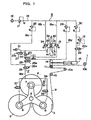
- the fluid pressure circuit illustrated therein is an example of pneumatic pressure circuit embodied in a paper feeding section of a rotary printing machine.
- the fluid pressure contains other gas pressure and liquid pressure such as hydraulic and oil pressure.
- a paper feeding section of a typical rotary printing machine includes a triradiate arm 1 which is rotatively supported by a center shaft 2. Each end of the triradiate arm 1 is assembled with a web-feed mechanism, not shown, for supporting a paper roll 3 (4, 5).
- the web-feed mechanism includes a brake mechanism 6 (7, 8) whose brake force is varied in response to the magnitude of pneumatic pressure fed to the brake mechanism so that feeding speed of the paper roll 3 (4, 5) can be controlled.
- the paper feeding section further includes a plurality of guide rollers 10, 10a, 10b, and a floating roller 11 to guide the paper web 9 fed from the paper roll 3 towards a printing section, not shown.
- the floating roller 11 belongs to a tension detecting mechanism A.
- this paper feeding section includes a paper splicing mechanism, not shown, and a tension control device according to the present invention.
- the paper splicing mechanism succeedingly splices a new roll 4 (5) to the preceding roll 3 (4) when remaining amount of this preceding roll 3 (4) reaches to a predetermined value, and cuts off the remaining paper of the preceding roll.
- the tension control device changes the pneumatic pressure fed to the brake mechanism 6 (7, 8) in response to the change of tension applied to the paper web 9 running from the paper roll 3 (4, 5) and a predetermined operation signal, to control the brake force for adjusting the feeding speed of the roll 3 (4, 5) in order to achieve the tension control on the running paper web 9.
- the tension control device is composed of the above described tension detecting mechanism A, a fluid pressure feeding conduit system B, a first brake force adjusting mechanism C, a second brake force adjusting mechanism D, a first switching mechanism E, a second switching mechanism F, and a tension control mechanism G for paper leading.
- the tension detecting mechanism A is so designed as to detect the tension applied to the paper web 9 running, and comprises the floating roller 11 for guiding the paper web 9 fed from the paper roll 3 (4, 5), a single arm 14 one end of which is pivotally supported by a pivot 13 so as to move the arm 14 angularly and the other end of which supports the floating roller 11 rotatable, and an air cylinder 15 as a force applying means for applying a constant force to the arm 14 against the tension applied to the paper web 9. Pneumatic pressure fed to the air cylinder 15 is adjusted by a regulator 30.
- the fluid pressure feeding conduit system B shown in this embodiment uses pneumatic pressure and includes a conduit group 18 communicated between the brake mechanism 6 (7, 8) and a pneumatic pressure source 16 for feeding pneumatic pressure to the brake mechanism 6 (7, 8).
- the conduit group 18 contains first, second, third and fourth upper conduits 18a, 18b, 18c and 18d which are respectively connected to the pneumatic pressure source 16, and a lower conduit 18z connected to the brake mechanisms 6, 7 and 8, respectively.
- the conduit system B further includes a first regulator 17 for adjusting pneumatic pressure fed to the first and second upper conduits 18a and 18b, a second regulator 28 for adjusting pneumatic pressure fed to the third upper conduit 18c, and a third regulator 29 for adjusting pneumatic pressure fed to the fourth upper conduit 18d.
- the first upper conduit 18a is provided with a first displacement-pneumatic pressure converter 19 in a normal running mode for the first brake force adjusting mechanism C.
- the second upper conduit 18b is also provided with a second displacement-pneumatic pressure converter 34 in an emergency stop mode for the second brake force adjusting mechanism D.
- the lower conduit 18z is branched at its lower end into three branch conduits which are connected respectively to the brake mechanisms 6, 7 and 8 mounted on the roll supporters. These branch conduits are further provided with electromagnetic valves 35, 36 and 37, respectively, to alternatively switch the branch conduits between open and close.
- the first and second brake force adjusting mechanisms C and D are so arranged in the fluid pressure feeding conduit system B that they are actuated in linkage with the tension detecting mechanism A to change the pneumatic pressure fed to the brake mechanism 6 (7, 8) for adjusting its brake force.
- the first brake force adjusting mechanism C includes a normal operation cam 20 which is angularly moved about the pivot 13 in linkage with the angular movement of the single arm 14, and the first displacement-pneumatic pressure converter 19 which is disposed in the first upper conduit 18a and actuated by the cam 20.
- this converter 19 is a deceleration valve having a cam follower 21.
- the second brake force adjusting mechanism D includes an emergency stop cam 32 which is shaped slightly different from the cam surface of the normal operation cam 20 and angularly moved about the pivot 13 in linkage with the angular movement of the single arm 14, and the second displacement-pneumatic pressure converter 34 which is disposed in the second upper conduit 18b and actuated by the cam 32.
- this converter 34 is also a deceleration valve having a cam follower 33.
- the first and second switching mechanisms E and F are arranged in the conduit system B and actuated in response to predetermined operation signals to switch selectively one of the upper conduits 18a, 18b and 18c to be communicated with the lower conduit 18z.
- the first switching mechanism E is actuated in response to an emergency stop signal of this printing system and then the first upper conduit 18a is closed and the second upper conduit 18b is simultaneously opened to establish the communication with the lower conduit 18z.
- the first switching mechanism E includes an electromagnetic valve 27 which is actuated in response to predetermined emergency stop signals, and a shuttle valve 23, a throttle valve 31 and a solenoid 27a which are respectively moved in linkage with the motion of the valve 27.
- the second switching mechanism F is actuated when the paper feeding section starts to splice the preceding roll to the succeeding roll, and then the third upper conduit 18c is opened for a predetermined period to establish the communication with the lower conduit 18z.
- the second switching mechanism F further includes an electromagnetic valve 26 and a solenoid 26a which are actuated in response to a cutting operation signal generated when the remaining paper of the preceding roll 3 is cut.
- the tension control mechanism G includes a third switching mechanism for establishing the communication between the fourth upper conduit 18d and the lower conduit 18z, and controls the tension for leading the paper web 9 through the printing section of this rotary printing machine prior to the printing operation.
- This third switching mechanism is composed of two electromagnetic valves 24 and 25, and two solenoids 24a and 25a which are actuated in response to a signal representing paper leading operation.
- the paper web 9 must be always applied with the optimum tension which depends on a correlation between the rotating speed of a plate cylinder, not shown, of the rotary printing machine and the brake force against the rotating motion of the roll 3 (4, 5) for feeding the paper web 9.
- Fig. 1 shows that the triradiate arm 1 supports at the top ends the paper roll 3 which now feeds the paper web 9, and the paper rolls 4 and 5 in their waiting positions.
- the paper web 9 fed from the roll 3 is traveled toward the printing section, not shown, through in order of the guide rollers 10 and 10a, the floating roller 11, and the guide roller 10b.
- the brake mechanisms 6, 7 and 8 will generate respective brake forces in substantially proportion to the magnitude of pneumatic pressures fed to these mechanisms.
- the roller 11 Since the floating roller 11 is mounted on the end of the single arm 14 which can be angularly moved about the pivot 13, the roller 11 will be also angularly moved counter-clockwise in Fig. 1 by the tension applied to the paper web 9.
- the center of the single arm 14 is connected to the rod end of the air cylinder 15 to apply a predetermined constant force generated by the air cylinder 15 to make the arm 14 turn clockwise in Fig. 1.
- the air cylinder 15 is supplied with pneumatic pressure from the pressure source 16 via the first regulator 17, the conduit 18, and the regulator 30.
- the single arm 14 will be held in the angular phase which represents that the tension applied to the floating roller 11 is balanced with the pneumatic pressure adjusted by the regulator 30. This angular phase will be varied in accordance with various running modes of the paper web 9.
- the tension applied to the paper web 9 is generated between the stretching force by the plate cylinder of the printing section and the brake force applied to the roll 3, and will be increased as the brake force greater. Accordingly, this tension can be stabilized by keeping the magnitude of pneumatic pressure to be fed to the brake mechanisms 6, 7 and 8 be controlled substantially inverse proportion to the magnitude of the tension applied to the paper web 9.
- the first displacement-pneumatic pressure converter 19 is actuated in linkage with the angular motion of the single arm 14.
- the pivot 13 of the single arm 14 for supporting the floating roller 11 is provided at the right side in Fig. 1 with the normal operation cam 20 having a cam surface gradually enlarging from the bottom to the top.
- the cam follower 21 follows the angular motion of the single arm 14 in accordance with the change in the tension applied to the paper web 9, and thus the open degree of the first displacement-pneumatic pressure converter 19 is adjusted.
- the pneumatic pressure is fed from the pressure source 16 to the first displacement-pneumatic pressure converter 19 through the first regulator 17, the conduit 18, and the first upper conduit 18a. Further the pneumatic pressure output from the converter 19 is fed to the brake mechanism 6 (7, 8) through the shuttle valve 23 which is a part of the first switching mechanism E, and the lower conduit 18z.
- the normal operation cam 20 is also turned counter-clockwise and thus the first converter 19 gradually decreases the pneumatic pressure to be fed to the brake mechanism 6 (7, 8).
- the paper web 9 can be easily fed from the roll 3 (4, 5). Consequently, the paper web 9 is always applied with a stable tension in the above described automatic control manner.
- the tension applied to the paper web 9 gradually decreases.
- the single arm 14 is angularly moved clockwise in Fig. 1 by the predetermined bias force generated by the air cylinder 15.
- the solenoid 27a is energized in response to the emergency stop signal from the printing section, not shown.
- the electromagnetic valve 27 of the first switching mechanism E is actuated by this solenoid 27a , and then the communication between the second upper conduit 18b and the lower conduit 18z is established.
- the emergency stop cam 32 is angularly moved clockwise in Fig. 1 by the angular clockwise motion of the single arm 14.
- the emergency stop cam 32 has a cam surface slightly different from that of the normal operation cam 20 so that the second converter 34 actuated through the cam follower 33 can feed substantially twice pneumatic pressure to the brake mechanism 6 (7, 8) in comparison with the case of the normal operation cam 20. As a result, the brake mechanism 6 (7, 8 ) can generate substantial twice brake force.
- the solenoid 27a is dis-energized in response to the signal generated when the emergency stop operation has been completed. Then the electromagnetic valve 27 of the first switching mechanism E is switched to allow the increased pneumatic pressure to be released into the ambient air through the throttle valve 31. Whenever this increased pneumatic pressure becomes lower than the pneumatic pressure output of the first displacement-pneumatic pressure converter 19, the shuttle valve 23 is switched to allow the converter 19 to feed the output pneumatic pressure to the lower conduit 18z. Finally, the paper web 9 and the paper roll 3 (4, 5) have been already set to restart the printing operation.
- the brake force for the brake mechanism 6 (7, 8) should be firstly decreased to pull out the paper web 9 from the paper roll 3 (4, 5).
- a paper leading switch not shown, is turned on, the solenoid 24a is energized by a paper leading signal from this switch. Then the electromagnetic valve 24 of the third switching mechanism in the tension control mechanism G makes the first upper conduit 18a close and allows the pneumatic pressure in the lower conduit 18z to be released into the ambient air.
- the solenoid 25a is also energized to switch the electromagnetic valve 25 to establish the communication between the fourth upper conduit 18d and the lower conduit 18z.
- the lower pneumatic pressure out of the regulator 29 is fed to the brake mechanism 6 (7, 8) so that the brake force of the brake mechanism 6 (7, 8) can be decreased to realize the optimum tension level for paper leading operation.
- the paper leading operation has been completed, the paper leading signal is vanished.
- the solenoids 24a and 25a are both switched to release the electromagnetic valves 24 and 25. According to this switching motion, the first upper conduit 18a for the normal operation becomes alive to reset this printing system into its standby mode.
- the tension control device can minimize such fluctuation of the tension applied to the paper web 9 and further quickly and easily performs an automatic tension control and stabilizing operation by only automatically working the pneumatic pressure control system.
- the inertial force applied to the preceding roll 3 (4, 5) also becomes minimum. Accordingly, a small brake force can realize a sufficient tension applied to the paper web 9.
- the single arm 14 is angularly moved counter-clockwise in Fig. 1 and the cam follower 21 is in contact with the narrow section of the normal operation cam 20. As a result, the first displacement-pneumatic pressure converter 19 generates the reduced pneumatic pressure.
- the paper web 9 Upon splicing, the paper web 9 is spliced on the instant from the smallest roll 3 (4, 5) to the greater roll 4 (5, 3) and then the paper web 9 is fed from the greater roll 4 (5, 3). Since the greater roll 4 (5, 3) is subjected to a greater inertial force, the brake force required to the brake mechanism 6 (7, 8) should be instantly changed from the minimum to the maximum. This changing speed is so fast that the brake force can not be adequately controlled through the first and second displacement-pneumatic pressure converters 19 and 34.
- the succeeding roll 4 (5, 3) is driven by any conventional roll driver, not shown, so as to coincide the circumferential speed of the succeeding roll with the running speed of the paper web 9 fed from the preceding roll 3 (4, 5) and then the paper web 9 is forcibly brought into contact with the circumferential surface of the succeeding roll 4 by a conventional splicing mechanism, not shown.
- the preceding paper web is bonded to the forward end of the succeeding paper web by means of any adhesive.
- a conventional cutting means cuts the portion of the preceding paper web 9 between the spliced section and the preceding roll 3 (4, 5). In response to the cutting signal output from this cutting means, the brake force fed to the brake mechanism 6 (7, 8) is instantly increased for a predetermined period.
- the solenoid 26a is energized in response to this cutting signal, and thus the electromagnetic valve 26 of the second switching mechanism F is switched to establish the communication between the third upper conduit 18c and the lower conduit 18z.
- the increased pneumatic pressure adjusted by the regulator 28 is fed to the brake mechanism 7 (6, 8) of the succeeding roll 4 (5, 3) through the electromagnetic valve 36, and then the succeeding roll 4 (5, 3) is instantly restricted by the great brake force.
- the solenoid 26a is automatically dis-energized after a predetermined period by a timer, not shown, and thus the electromagnetic valve 26 is returned to the initial position shown in Fig. 1.
- the first upper conduit 18a is communicated with the lower conduit 18z and the increased pneumatic pressure is introduced into the first upper conduit 18a.
- the normal operation pneumatic pressure circuit composed of the first upper conduit 18a and the lower conduit 18z acts as the automatic tension control.
- this embodiment of the tension control device upon splicing operation, the increased pneumatic pressure is fed to brake mechanism 6 (7, 8) for one second, as an example, to temporarily maintain the great brake force. During such period, the normal operation state is recovered and reset to begin a normal printing operation. Accordingly, this system can stabilize the tension applied to the paper web 9 within an extremely short period in comparison with conventional systems even when the maximum fluctuation of the brake force occurs.
- a regulator 12 and an electromagnetic valve 22 configure a pneumatic circuit arranged between the regulator 30 and the air cylinder 15, which circuit becomes effective for using another paper roll having different width.
- the tension control device having the above described aspect can actually and quickly select required switching mechanism under any conditions such as emergency, paper splicing operation, paper leading operation as well as ordinarily tension control operation for external pester and paper break so that the tension applied to paper web can be automatically and always controlled to keep in the optimum level.
- the tension control device having the above described aspect can temporarily feed a higher fluid pressure to the brake mechanism within a short period required for following and dealing motion in a normal brake control operation to deal rapid changes, and therefore can automatically stabilize the tension applied to paper web more quickly in comparison with conventional devices.
- the tension control device ensures a continuous printing operation free from stopping owing to loosening and breaking in paper web, and a paper leading operation with keeping the optimum tension applied to the paper web.
Landscapes
- Inking, Control Or Cleaning Of Printing Machines (AREA)
- Controlling Rewinding, Feeding, Winding, Or Abnormalities Of Webs (AREA)
- Replacement Of Web Rolls (AREA)
- Rotary Presses (AREA)
Claims (2)
- Dispositif de contrôle de la tension destiné à être utilisé dans une machine rotative d'impression qui comprend une pluralité d'alimentations de nappe, chacune équipée d'un rouleau de papier (3, 4, 5) et d'un mécanisme de freinage (6, 7, 8) dont la force de freinage peut varier en réponse à la pression hydraulique délivrée par une source de pression (16) et qui peut ensuite réaliser le raccordement à un nouveau rouleau (4, 5 ou 3) lorsqu'un rouleau précédent (3, 4 ou 5) atteint un niveau résiduel prédéterminé, comprenant:caractérisé en ce queun mécanisme (A) de détection de tension qui comprend un rouleau danseur (11) qui sert à guider la nappe de papier (9) qui provient de l'un des rouleaux (3, 4, 5), un bras simple (14) dont une extrémité est soutenue à pivotement par un pivot (13) de manière à déplacer ledit bras (14) angulairement et dont l'autre extrémité soutient à rotation ledit rouleau dansant (11), et un moyen d'application de force pour appliquer une force constante sur ledit bras simple (14) en opposition à la tension appliquée sur ladite nappe de papier (9), de telle sorte que ledit bras simple (14) puisse être déplacé angulairement en réponse à la valeur de la tension appliquée sur la nappe de papier (9);un système (B) de conduit d'alimentation en pression hydraulique qui comprend un premier conduit supérieur (18a) et un deuxième conduit supérieur (18b) pour délivrer des fluides qui présentent des pressions respectives différentes dans un conduit inférieur (18z) relié aux mécanismes de freinage (6, 7, 8) mentionnés plus haut et associés aux rouleaux de papier (3, 4, 5) mentionnés plus haut;un premier mécanisme (C) d'ajustement de la force de freinage associé au premier conduit supérieur (18a) mentionné plus haut, pour amener la pression de sortie de ce mécanisme (C) d'ajustement de la force de freinage à être une première pression qui est réduite lorsque la tension appliquée sur la nappe de papier (9) augmente;un deuxième mécanisme (D) d'ajustement de la force de freinage associé au deuxième conduit supérieur (18b) mentionné plus haut pour amener la pression de sortie de ce mécanisme (D) d'ajustement de la force de freinage à être une deuxième pression qui est réduite lorsque la tension appliquée sur la nappe de papier (9) augmente; etun premier mécanisme de commutation (E) entre le premier conduil supérieur (18a) mentionné plus haut, le deuxième conduit supérieur (18b) mentionné plus haut et le conduit inférieur (18z) mentionné plus haut, qui est agencé pour commuter en réponse à l'un parmi plusieurs signaux d'urgence prédéterminés entre ledit premier conduit supérieur (18a) et ledit deuxième conduit supérieur (18b) pour assurer la communication entre ledit deuxième conduit supérieur (18b) et ledit conduit inférieur (18z);
le deuxième mécanisme (D) d'ajustement de la force de freinage est conçu de telle sorte que ladite deuxième pression est supérieure à la première pression mentionnée plus haut pour la même tension que plus haut;
le système d'alimentation en pression hydraulique comprend au moins un troisième conduit supérieur (18c) pour délivrer un fluide qui présente une pression différente des pressions de fluide délivrées respectivement par le premier et le deuxième conduit supérieur (18a, 18b) au conduit inférieur (18z) relié aux mécanismes de freinage (6, 7, 8) mentionnés plus haut et associé aux rouleaux de papier (3, 4, 5) mentionnés plus haut; et
un deuxième mécanisme de commutation (F) est agencé entre le conduit inférieur (18z) mentionné plus haut et le troisième conduit supérieur (18c) mentionné plus haut pour délivrer une troisième pression supérieure au maximum de la deuxième pression, ledit deuxième mécanisme de commutation (F) étant situé plus bas que le premier mécanisme de commutation (E) mentionné plus haut et étant actionné en réponse à un signal d'opération de raccordement pour que la connexion entre ledit troisième conduit supérieur (18c) et ledit conduit inférieur (18z) ne soit réalisée que pendant un laps de temps prédéterminé. - Dispositif de contrôle de la tension selon la revendication 1, qui comprend en outre un mécanisme (G) de contrôle de la tension pour l'opération de guidage du papier, qui comprend un troisième mécanisme de commutation agencé entre le conduit inférieur (18z) mentionné plus haut et un quatrième conduit supérieur (18d) qui sert à délivrer une quatrième pression inférieure au minimum de la première pression mentionnée plus haut et qui est situé plus bas que le premier mécanisme de commutation, ledit troisième mécanisme de commutation étant actionné en réponse à un signal prédéterminé d'opération de raccordement pour permettre la liaison entre ledit quatrième conduit supérieur (18d) et ledit conduit inférieur (18z) uniquement pendant un laps de temps prédéterminé pendant lequel le signal d'opération de raccordement est délivré.
Applications Claiming Priority (2)
| Application Number | Priority Date | Filing Date | Title |
|---|---|---|---|
| JP33400398 | 1998-11-25 | ||
| JP10334003A JP2981221B1 (ja) | 1998-11-25 | 1998-11-25 | 輪転機のウェブ紙張力制御装置 |
Publications (2)
| Publication Number | Publication Date |
|---|---|
| EP1004528A1 EP1004528A1 (fr) | 2000-05-31 |
| EP1004528B1 true EP1004528B1 (fr) | 2003-08-06 |
Family
ID=18272419
Family Applications (1)
| Application Number | Title | Priority Date | Filing Date |
|---|---|---|---|
| EP99108599A Expired - Lifetime EP1004528B1 (fr) | 1998-11-25 | 1999-05-07 | Dispositif de contrôle de tension pour une bande de papier dans une imprimante rotative |
Country Status (5)
| Country | Link |
|---|---|
| US (1) | US6073876A (fr) |
| EP (1) | EP1004528B1 (fr) |
| JP (1) | JP2981221B1 (fr) |
| AT (1) | ATE246659T1 (fr) |
| DE (1) | DE69910151T2 (fr) |
Families Citing this family (10)
| Publication number | Priority date | Publication date | Assignee | Title |
|---|---|---|---|---|
| US7017485B2 (en) * | 2000-03-24 | 2006-03-28 | Goss International Americas, Inc. | Device and method for controlling web tension |
| DE10060757A1 (de) * | 2000-12-07 | 2002-06-13 | Heidelberger Druckmasch Ag | Fliegender Rollenwechsler in einer Rollenrotationsdruckmaschine |
| US20040000608A1 (en) * | 2002-06-26 | 2004-01-01 | Metza John Andrew | Methods and mechanism for providing variable torque with variable torque resolution to rotation of a web roll |
| US7007883B2 (en) | 2003-02-05 | 2006-03-07 | Adalis Corporation | Apparatus and method for dispensing elongated material |
| US7104493B2 (en) | 2003-02-05 | 2006-09-12 | Adalis Corporation | Dispensing apparatus and method |
| US7201345B2 (en) * | 2003-09-30 | 2007-04-10 | Rockwell Automation Technologies, Inc. | Reeled material splicing method and apparatus |
| US20090023526A1 (en) * | 2007-07-19 | 2009-01-22 | Gilles Larouche | Pneumatic base for facilitating the installation and tensioning of a drive belt |
| DE102008024367A1 (de) * | 2008-05-20 | 2009-12-03 | Khs Ag | Rollen- oder Pufferspeicher für ein bahnförmiges Flachmaterial |
| EP3016898B1 (fr) * | 2013-07-01 | 2017-03-15 | Bobst Mex Sa | Dispositif de freinage d'une bobine de bande |
| JP6114869B1 (ja) * | 2016-10-25 | 2017-04-12 | 株式会社東京機械製作所 | 連続紙の張力制御装置及び張力制御方法 |
Family Cites Families (12)
| Publication number | Priority date | Publication date | Assignee | Title |
|---|---|---|---|---|
| US2965326A (en) * | 1957-12-18 | 1960-12-20 | Cameron Machine Co | Apparatus for controlling tension in a web |
| GB1171641A (en) * | 1966-03-10 | 1969-11-26 | Timsons Ltd | Means controlling tension in a travelling web during drawing from a reel and re-reeling |
| GB1089340A (en) * | 1966-03-28 | 1967-11-01 | Plamag Plauener Druckmaschinen | Improvements in or relating to web feeding apparatus |
| US3414208A (en) * | 1966-09-02 | 1968-12-03 | Jr Richard A Butler | Apparatus for controlling the unwinding of web |
| US3813052A (en) * | 1973-04-13 | 1974-05-28 | Arcata Graphics | Web tension control system |
| US4000865A (en) * | 1975-08-27 | 1977-01-04 | Batson-Cook Company | Controlled tension let-off for unwinding rolls of material |
| DE2560056C2 (de) * | 1975-10-03 | 1980-12-11 | Bruderhaus Maschinen Gmbh, 7410 Reutlingen | Pneumatische Bandzugregeleinrichtung |
| DE2965013D1 (en) * | 1978-12-22 | 1983-04-14 | Tidland Gmbh | Device for regulating the tension in a web |
| JPS6144786A (ja) * | 1984-08-08 | 1986-03-04 | Sony Corp | 半導体単結晶薄膜の製造方法 |
| DE3608182A1 (de) * | 1986-03-12 | 1987-10-01 | Roland Man Druckmasch | Vorrichtung zur regelung der spannung einer drucktraegerbahn mit einer notstoppeinrichtung |
| JPH02300053A (ja) * | 1989-05-12 | 1990-12-12 | Tokyo Kikai Seisakusho Ltd | 印刷紙張力制御装置 |
| JPH0545501A (ja) * | 1991-08-15 | 1993-02-23 | Matsushita Electric Ind Co Ltd | 複合型光学素子およびその製造方法 |
-
1998
- 1998-11-25 JP JP10334003A patent/JP2981221B1/ja not_active Expired - Fee Related
-
1999
- 1999-05-06 US US09/306,415 patent/US6073876A/en not_active Expired - Fee Related
- 1999-05-07 DE DE69910151T patent/DE69910151T2/de not_active Expired - Fee Related
- 1999-05-07 EP EP99108599A patent/EP1004528B1/fr not_active Expired - Lifetime
- 1999-05-07 AT AT99108599T patent/ATE246659T1/de not_active IP Right Cessation
Also Published As
| Publication number | Publication date |
|---|---|
| JP2981221B1 (ja) | 1999-11-22 |
| EP1004528A1 (fr) | 2000-05-31 |
| ATE246659T1 (de) | 2003-08-15 |
| DE69910151D1 (de) | 2003-09-11 |
| JP2000158629A (ja) | 2000-06-13 |
| US6073876A (en) | 2000-06-13 |
| DE69910151T2 (de) | 2004-06-24 |
Similar Documents
| Publication | Publication Date | Title |
|---|---|---|
| EP1004528B1 (fr) | Dispositif de contrôle de tension pour une bande de papier dans une imprimante rotative | |
| JP3535255B2 (ja) | 油圧駆動制御装置 | |
| US4709872A (en) | Web tension control and emergency stop system | |
| EP0056865B1 (fr) | Dispositif de commande hydraulique | |
| US2491636A (en) | High-speed edging | |
| US2969930A (en) | Continuous rewinder for web material | |
| US5186409A (en) | Tension control device for printing paper | |
| US3813052A (en) | Web tension control system | |
| US5484352A (en) | Switch for detecting operation of control valve spool | |
| JP2002521633A (ja) | 油圧回路 | |
| JPH10147958A (ja) | 建設機械走行システムの制御装置 | |
| US5797561A (en) | Unwinding station for fiber webs including a device for performing a flying splice | |
| KR100333281B1 (ko) | 트레일러차량의 브레이크장치 | |
| JPH0624689A (ja) | ウインチの制御装置 | |
| KR0170155B1 (ko) | 클러치 자동 제어장치 | |
| JPH0313144B2 (fr) | ||
| JPH01126405A (ja) | 空気圧回路 | |
| JPH06144377A (ja) | 減速逆転機の中立ブレーキ解除装置 | |
| JPS62191638A (ja) | オ−トデセル装置付きエンジンの制御方法 | |
| JPS6144786B2 (fr) | ||
| KR200142286Y1 (ko) | 중장비의 유압장치 | |
| JP2816762B2 (ja) | 輪転印刷機の給紙機における巻取紙の停止装置 | |
| KR0152404B1 (ko) | 휠타입 굴삭기의 자동주행 장치 | |
| JPH073775Y2 (ja) | ケーブルけん引機 | |
| JP2694300B2 (ja) | 油圧漁撈ウインチ駆動装置 |
Legal Events
| Date | Code | Title | Description |
|---|---|---|---|
| PUAI | Public reference made under article 153(3) epc to a published international application that has entered the european phase |
Free format text: ORIGINAL CODE: 0009012 |
|
| AK | Designated contracting states |
Kind code of ref document: A1 Designated state(s): AT CH DE GB LI |
|
| AX | Request for extension of the european patent |
Free format text: AL;LT;LV;MK;RO;SI |
|
| 17P | Request for examination filed |
Effective date: 20001012 |
|
| AKX | Designation fees paid |
Free format text: AT CH DE GB LI |
|
| 17Q | First examination report despatched |
Effective date: 20020424 |
|
| GRAH | Despatch of communication of intention to grant a patent |
Free format text: ORIGINAL CODE: EPIDOS IGRA |
|
| GRAH | Despatch of communication of intention to grant a patent |
Free format text: ORIGINAL CODE: EPIDOS IGRA |
|
| GRAA | (expected) grant |
Free format text: ORIGINAL CODE: 0009210 |
|
| AK | Designated contracting states |
Designated state(s): AT CH DE GB LI |
|
| REG | Reference to a national code |
Ref country code: GB Ref legal event code: FG4D |
|
| REG | Reference to a national code |
Ref country code: CH Ref legal event code: EP |
|
| REF | Corresponds to: |
Ref document number: 69910151 Country of ref document: DE Date of ref document: 20030911 Kind code of ref document: P |
|
| REG | Reference to a national code |
Ref country code: CH Ref legal event code: NV Representative=s name: PATENTANWAELTE SCHAAD, BALASS, MENZL & PARTNER AG |
|
| PG25 | Lapsed in a contracting state [announced via postgrant information from national office to epo] |
Ref country code: GB Free format text: LAPSE BECAUSE OF NON-PAYMENT OF DUE FEES Effective date: 20040507 Ref country code: AT Free format text: LAPSE BECAUSE OF NON-PAYMENT OF DUE FEES Effective date: 20040507 |
|
| PG25 | Lapsed in a contracting state [announced via postgrant information from national office to epo] |
Ref country code: LI Free format text: LAPSE BECAUSE OF NON-PAYMENT OF DUE FEES Effective date: 20040531 Ref country code: CH Free format text: LAPSE BECAUSE OF NON-PAYMENT OF DUE FEES Effective date: 20040531 |
|
| PLBE | No opposition filed within time limit |
Free format text: ORIGINAL CODE: 0009261 |
|
| STAA | Information on the status of an ep patent application or granted ep patent |
Free format text: STATUS: NO OPPOSITION FILED WITHIN TIME LIMIT |
|
| 26N | No opposition filed |
Effective date: 20040507 |
|
| PG25 | Lapsed in a contracting state [announced via postgrant information from national office to epo] |
Ref country code: DE Free format text: LAPSE BECAUSE OF NON-PAYMENT OF DUE FEES Effective date: 20041201 |
|
| GBPC | Gb: european patent ceased through non-payment of renewal fee |
Effective date: 20040507 |
|
| REG | Reference to a national code |
Ref country code: CH Ref legal event code: PL |