EP0998217B1 - Applicateur jetable d'ultrasons haute intensite a faisceau concentre - Google Patents
Applicateur jetable d'ultrasons haute intensite a faisceau concentre Download PDFInfo
- Publication number
- EP0998217B1 EP0998217B1 EP98928831A EP98928831A EP0998217B1 EP 0998217 B1 EP0998217 B1 EP 0998217B1 EP 98928831 A EP98928831 A EP 98928831A EP 98928831 A EP98928831 A EP 98928831A EP 0998217 B1 EP0998217 B1 EP 0998217B1
- Authority
- EP
- European Patent Office
- Prior art keywords
- magnetic resonance
- energy
- frame
- subject
- computer
- Prior art date
- Legal status (The legal status is an assumption and is not a legal conclusion. Google has not performed a legal analysis and makes no representation as to the accuracy of the status listed.)
- Expired - Lifetime
Links
- 238000002604 ultrasonography Methods 0.000 title claims abstract description 16
- 239000012530 fluid Substances 0.000 claims abstract description 13
- 230000005540 biological transmission Effects 0.000 claims description 5
- 230000005291 magnetic effect Effects 0.000 description 143
- 238000011282 treatment Methods 0.000 description 73
- 230000003068 static effect Effects 0.000 description 63
- 238000000034 method Methods 0.000 description 61
- 210000001519 tissue Anatomy 0.000 description 56
- 238000012360 testing method Methods 0.000 description 32
- 238000010438 heat treatment Methods 0.000 description 28
- 238000003384 imaging method Methods 0.000 description 22
- 238000002595 magnetic resonance imaging Methods 0.000 description 21
- 230000033001 locomotion Effects 0.000 description 20
- 238000004804 winding Methods 0.000 description 18
- 238000011287 therapeutic dose Methods 0.000 description 12
- 230000000875 corresponding effect Effects 0.000 description 10
- 230000001276 controlling effect Effects 0.000 description 9
- XLYOFNOQVPJJNP-UHFFFAOYSA-N water Substances O XLYOFNOQVPJJNP-UHFFFAOYSA-N 0.000 description 9
- 206010020843 Hyperthermia Diseases 0.000 description 8
- 239000002826 coolant Substances 0.000 description 8
- 230000036031 hyperthermia Effects 0.000 description 8
- 230000008569 process Effects 0.000 description 8
- 238000002560 therapeutic procedure Methods 0.000 description 8
- 238000011088 calibration curve Methods 0.000 description 7
- 238000002679 ablation Methods 0.000 description 6
- 230000003902 lesion Effects 0.000 description 6
- 238000012544 monitoring process Methods 0.000 description 6
- 238000013519 translation Methods 0.000 description 6
- 238000013459 approach Methods 0.000 description 5
- 230000008859 change Effects 0.000 description 5
- 230000000007 visual effect Effects 0.000 description 5
- 230000000694 effects Effects 0.000 description 4
- 230000006872 improvement Effects 0.000 description 4
- 239000000463 material Substances 0.000 description 4
- 210000003708 urethra Anatomy 0.000 description 4
- 238000012937 correction Methods 0.000 description 3
- 239000003814 drug Substances 0.000 description 3
- 230000002401 inhibitory effect Effects 0.000 description 3
- 239000003550 marker Substances 0.000 description 3
- 210000000056 organ Anatomy 0.000 description 3
- 239000000523 sample Substances 0.000 description 3
- 238000010408 sweeping Methods 0.000 description 3
- IJGRMHOSHXDMSA-UHFFFAOYSA-N Atomic nitrogen Chemical compound N#N IJGRMHOSHXDMSA-UHFFFAOYSA-N 0.000 description 2
- 206010028980 Neoplasm Diseases 0.000 description 2
- PNEYBMLMFCGWSK-UHFFFAOYSA-N aluminium oxide Inorganic materials [O-2].[O-2].[O-2].[Al+3].[Al+3] PNEYBMLMFCGWSK-UHFFFAOYSA-N 0.000 description 2
- 210000003484 anatomy Anatomy 0.000 description 2
- 238000003491 array Methods 0.000 description 2
- 239000003990 capacitor Substances 0.000 description 2
- 238000001816 cooling Methods 0.000 description 2
- 238000013461 design Methods 0.000 description 2
- 229940079593 drug Drugs 0.000 description 2
- 230000005294 ferromagnetic effect Effects 0.000 description 2
- 239000007788 liquid Substances 0.000 description 2
- 229920000642 polymer Polymers 0.000 description 2
- 230000004044 response Effects 0.000 description 2
- 238000003860 storage Methods 0.000 description 2
- 230000001225 therapeutic effect Effects 0.000 description 2
- BQCIDUSAKPWEOX-UHFFFAOYSA-N 1,1-Difluoroethene Chemical compound FC(F)=C BQCIDUSAKPWEOX-UHFFFAOYSA-N 0.000 description 1
- 206010004446 Benign prostatic hyperplasia Diseases 0.000 description 1
- 241000271460 Crotalus cerastes Species 0.000 description 1
- 239000004593 Epoxy Substances 0.000 description 1
- XEEYBQQBJWHFJM-UHFFFAOYSA-N Iron Chemical group [Fe] XEEYBQQBJWHFJM-UHFFFAOYSA-N 0.000 description 1
- 229920006370 Kynar Polymers 0.000 description 1
- 239000002033 PVDF binder Substances 0.000 description 1
- 239000004698 Polyethylene Substances 0.000 description 1
- 208000004403 Prostatic Hyperplasia Diseases 0.000 description 1
- 235000004443 Ricinus communis Nutrition 0.000 description 1
- 240000000528 Ricinus communis Species 0.000 description 1
- 208000027418 Wounds and injury Diseases 0.000 description 1
- 238000010521 absorption reaction Methods 0.000 description 1
- 230000003213 activating effect Effects 0.000 description 1
- 230000015572 biosynthetic process Effects 0.000 description 1
- 230000036760 body temperature Effects 0.000 description 1
- 238000009529 body temperature measurement Methods 0.000 description 1
- 238000004590 computer program Methods 0.000 description 1
- 238000005094 computer simulation Methods 0.000 description 1
- 230000002596 correlated effect Effects 0.000 description 1
- 239000006071 cream Substances 0.000 description 1
- 238000002059 diagnostic imaging Methods 0.000 description 1
- 238000010586 diagram Methods 0.000 description 1
- 238000006073 displacement reaction Methods 0.000 description 1
- 238000009826 distribution Methods 0.000 description 1
- 230000009977 dual effect Effects 0.000 description 1
- 238000007772 electroless plating Methods 0.000 description 1
- 238000009713 electroplating Methods 0.000 description 1
- 239000008393 encapsulating agent Substances 0.000 description 1
- 238000010336 energy treatment Methods 0.000 description 1
- 239000003302 ferromagnetic material Substances 0.000 description 1
- 230000004907 flux Effects 0.000 description 1
- 239000011521 glass Substances 0.000 description 1
- 239000001307 helium Substances 0.000 description 1
- 229910052734 helium Inorganic materials 0.000 description 1
- SWQJXJOGLNCZEY-UHFFFAOYSA-N helium atom Chemical compound [He] SWQJXJOGLNCZEY-UHFFFAOYSA-N 0.000 description 1
- 238000007689 inspection Methods 0.000 description 1
- 230000003993 interaction Effects 0.000 description 1
- 230000002452 interceptive effect Effects 0.000 description 1
- 239000010410 layer Substances 0.000 description 1
- 238000001646 magnetic resonance method Methods 0.000 description 1
- 238000004519 manufacturing process Methods 0.000 description 1
- 230000013011 mating Effects 0.000 description 1
- 230000007246 mechanism Effects 0.000 description 1
- 239000000203 mixture Substances 0.000 description 1
- 229910052757 nitrogen Inorganic materials 0.000 description 1
- 238000005457 optimization Methods 0.000 description 1
- 230000005693 optoelectronics Effects 0.000 description 1
- 229920000515 polycarbonate Polymers 0.000 description 1
- 239000004417 polycarbonate Substances 0.000 description 1
- -1 polyethylene Polymers 0.000 description 1
- 229920000573 polyethylene Polymers 0.000 description 1
- 229920000139 polyethylene terephthalate Polymers 0.000 description 1
- 229920002981 polyvinylidene fluoride Polymers 0.000 description 1
- 238000003825 pressing Methods 0.000 description 1
- 238000012545 processing Methods 0.000 description 1
- 210000002307 prostate Anatomy 0.000 description 1
- 239000011241 protective layer Substances 0.000 description 1
- 238000001959 radiotherapy Methods 0.000 description 1
- 230000009467 reduction Effects 0.000 description 1
- 238000005057 refrigeration Methods 0.000 description 1
- 230000003252 repetitive effect Effects 0.000 description 1
- 230000002441 reversible effect Effects 0.000 description 1
- 238000004544 sputter deposition Methods 0.000 description 1
- 238000010561 standard procedure Methods 0.000 description 1
- 239000002887 superconductor Substances 0.000 description 1
- 239000013589 supplement Substances 0.000 description 1
- 238000001356 surgical procedure Methods 0.000 description 1
- 238000003786 synthesis reaction Methods 0.000 description 1
- 238000012546 transfer Methods 0.000 description 1
- 238000009211 ultrasonic lithotripsy Methods 0.000 description 1
Images


Classifications
-
- A—HUMAN NECESSITIES
- A61—MEDICAL OR VETERINARY SCIENCE; HYGIENE
- A61N—ELECTROTHERAPY; MAGNETOTHERAPY; RADIATION THERAPY; ULTRASOUND THERAPY
- A61N7/00—Ultrasound therapy
- A61N7/02—Localised ultrasound hyperthermia
-
- A—HUMAN NECESSITIES
- A61—MEDICAL OR VETERINARY SCIENCE; HYGIENE
- A61B—DIAGNOSIS; SURGERY; IDENTIFICATION
- A61B34/00—Computer-aided surgery; Manipulators or robots specially adapted for use in surgery
- A61B34/70—Manipulators specially adapted for use in surgery
- A61B34/76—Manipulators having means for providing feel, e.g. force or tactile feedback
-
- A—HUMAN NECESSITIES
- A61—MEDICAL OR VETERINARY SCIENCE; HYGIENE
- A61B—DIAGNOSIS; SURGERY; IDENTIFICATION
- A61B5/00—Measuring for diagnostic purposes; Identification of persons
- A61B5/05—Detecting, measuring or recording for diagnosis by means of electric currents or magnetic fields; Measuring using microwaves or radio waves
- A61B5/055—Detecting, measuring or recording for diagnosis by means of electric currents or magnetic fields; Measuring using microwaves or radio waves involving electronic [EMR] or nuclear [NMR] magnetic resonance, e.g. magnetic resonance imaging
-
- A—HUMAN NECESSITIES
- A61—MEDICAL OR VETERINARY SCIENCE; HYGIENE
- A61B—DIAGNOSIS; SURGERY; IDENTIFICATION
- A61B17/00—Surgical instruments, devices or methods, e.g. tourniquets
- A61B17/22—Implements for squeezing-off ulcers or the like on the inside of inner organs of the body; Implements for scraping-out cavities of body organs, e.g. bones; Calculus removers; Calculus smashing apparatus; Apparatus for removing obstructions in blood vessels, not otherwise provided for
- A61B2017/22082—Implements for squeezing-off ulcers or the like on the inside of inner organs of the body; Implements for scraping-out cavities of body organs, e.g. bones; Calculus removers; Calculus smashing apparatus; Apparatus for removing obstructions in blood vessels, not otherwise provided for after introduction of a substance
- A61B2017/22087—Implements for squeezing-off ulcers or the like on the inside of inner organs of the body; Implements for scraping-out cavities of body organs, e.g. bones; Calculus removers; Calculus smashing apparatus; Apparatus for removing obstructions in blood vessels, not otherwise provided for after introduction of a substance photodynamic
-
- A—HUMAN NECESSITIES
- A61—MEDICAL OR VETERINARY SCIENCE; HYGIENE
- A61B—DIAGNOSIS; SURGERY; IDENTIFICATION
- A61B34/00—Computer-aided surgery; Manipulators or robots specially adapted for use in surgery
- A61B34/70—Manipulators specially adapted for use in surgery
- A61B34/74—Manipulators with manual electric input means
- A61B2034/742—Joysticks
-
- A—HUMAN NECESSITIES
- A61—MEDICAL OR VETERINARY SCIENCE; HYGIENE
- A61B—DIAGNOSIS; SURGERY; IDENTIFICATION
- A61B90/00—Instruments, implements or accessories specially adapted for surgery or diagnosis and not covered by any of the groups A61B1/00 - A61B50/00, e.g. for luxation treatment or for protecting wound edges
- A61B90/04—Protection of tissue around surgical sites against effects of non-mechanical surgery, e.g. laser surgery
- A61B2090/0472—Protection of tissue around surgical sites against effects of non-mechanical surgery, e.g. laser surgery against ultrasound energy
-
- A—HUMAN NECESSITIES
- A61—MEDICAL OR VETERINARY SCIENCE; HYGIENE
- A61B—DIAGNOSIS; SURGERY; IDENTIFICATION
- A61B90/00—Instruments, implements or accessories specially adapted for surgery or diagnosis and not covered by any of the groups A61B1/00 - A61B50/00, e.g. for luxation treatment or for protecting wound edges
- A61B90/36—Image-producing devices or illumination devices not otherwise provided for
- A61B90/37—Surgical systems with images on a monitor during operation
- A61B2090/374—NMR or MRI
-
- A—HUMAN NECESSITIES
- A61—MEDICAL OR VETERINARY SCIENCE; HYGIENE
- A61B—DIAGNOSIS; SURGERY; IDENTIFICATION
- A61B90/00—Instruments, implements or accessories specially adapted for surgery or diagnosis and not covered by any of the groups A61B1/00 - A61B50/00, e.g. for luxation treatment or for protecting wound edges
- A61B90/10—Instruments, implements or accessories specially adapted for surgery or diagnosis and not covered by any of the groups A61B1/00 - A61B50/00, e.g. for luxation treatment or for protecting wound edges for stereotaxic surgery, e.g. frame-based stereotaxis
-
- A—HUMAN NECESSITIES
- A61—MEDICAL OR VETERINARY SCIENCE; HYGIENE
- A61F—FILTERS IMPLANTABLE INTO BLOOD VESSELS; PROSTHESES; DEVICES PROVIDING PATENCY TO, OR PREVENTING COLLAPSING OF, TUBULAR STRUCTURES OF THE BODY, e.g. STENTS; ORTHOPAEDIC, NURSING OR CONTRACEPTIVE DEVICES; FOMENTATION; TREATMENT OR PROTECTION OF EYES OR EARS; BANDAGES, DRESSINGS OR ABSORBENT PADS; FIRST-AID KITS
- A61F7/00—Heating or cooling appliances for medical or therapeutic treatment of the human body
-
- A—HUMAN NECESSITIES
- A61—MEDICAL OR VETERINARY SCIENCE; HYGIENE
- A61N—ELECTROTHERAPY; MAGNETOTHERAPY; RADIATION THERAPY; ULTRASOUND THERAPY
- A61N7/00—Ultrasound therapy
- A61N2007/0056—Beam shaping elements
- A61N2007/0065—Concave transducers
-
- A—HUMAN NECESSITIES
- A61—MEDICAL OR VETERINARY SCIENCE; HYGIENE
- A61N—ELECTROTHERAPY; MAGNETOTHERAPY; RADIATION THERAPY; ULTRASOUND THERAPY
- A61N7/00—Ultrasound therapy
- A61N2007/0078—Ultrasound therapy with multiple treatment transducers
-
- A—HUMAN NECESSITIES
- A61—MEDICAL OR VETERINARY SCIENCE; HYGIENE
- A61N—ELECTROTHERAPY; MAGNETOTHERAPY; RADIATION THERAPY; ULTRASOUND THERAPY
- A61N7/00—Ultrasound therapy
- A61N2007/0086—Beam steering
- A61N2007/0091—Beam steering with moving parts, e.g. transducers, lenses, reflectors
-
- A—HUMAN NECESSITIES
- A61—MEDICAL OR VETERINARY SCIENCE; HYGIENE
- A61N—ELECTROTHERAPY; MAGNETOTHERAPY; RADIATION THERAPY; ULTRASOUND THERAPY
- A61N7/00—Ultrasound therapy
- A61N2007/0086—Beam steering
- A61N2007/0095—Beam steering by modifying an excitation signal
Definitions
- the present invention relates to the art of intrabody therapy involving application of energy to the body which may be monitored by magnetic resonance.
- Various forms of therapy can be applied within the body of a human or other mammalian subject by applying energy from outside of the subject.
- energy from outside of the subject.
- ultrasonic or radio frequency energy is applied from outside of the subject's body to heat the tissues.
- the applied energy can be focused to a small spot within the body so as to heat the tissues at such spot to a temperature sufficient to create a desired therepeautic effect.
- This technique can be used to selectively destroy unwanted tissue within the body.
- tumors or other unwanted tissues can be destroyed by applying heat to heat the tissue to a temperature sufficient to kill the tissue, commonly to about 60° to 80°C, without destroying adjacent normal tissues.
- Such a process is commonly referred to as "thermal ablation”.
- hyperthermia treatments include selectively heating tissues so as to selectively activate a drug or promote some other physiologic change in a selected portion of the subject's body.
- Other therapies use the applied energy to destroy foreign objects or deposits within the body as, for example, in ultrasonic lithotripsy.
- Magnetic resonance is used in medical imaging for diagnostic purposes.
- the region of the subject to be imaged is subjected to a strong magnetic field.
- Radio frequency signals are applied to the tissues of the subject within the imaging volume.
- atomic nuclei are excited by the applied radio frequency signals and emit faint radio frequency signals, referred to herein as magnetic resonance signals.
- the magnetic resonance signals can be obtained selectively from a limited region such as a two-dimensional slice of the subject's tissue.
- the frequency and phase of the signals from different portions of the slice can be made to vary with position in the slice. Using known techniques, it is possible to deconvolute the signals arising from different portions of the slice and to deduce certain properties of the tissues at each point within the slice from the signals.
- the data can be portrayed as a visible image and hence different temperatures can be shown by the differences in brightness or color within the displayed image.
- the location within the body being heated can be monitored by monitoring such a visible image during application of energy to the body.
- the degree of the heating can be monitored by monitoring T 1 for the heated regions. Magnetic resonance parameters other than T 1 can be portrayed or monitored in the same way.
- Magnetic resonance imaging instruments of the types commonly used for medical diagnostic applications include large, precise magnets which are arranged to impose a high magnetic field, typically about one Tesla or more over a relatively large imaging volume typically 10 cm or more in diameter.
- Certain magnetic resonance imaging static field magnets severely limit access to the subject.
- a solenoidal air-core superconducting magnet may have superconductive coils surrounding a tubular subject-receiving space. The subject lies on a bed which is advanced into the said tubular space so that the portion of the patient to be imaged is disposed inside of the tubular space.
- Iron core magnets typically have ferromagnetic frames defining opposed poles and a subject-receiving space lying between the poles.
- Permanent magnets or electromagnets are associated with the frame for providing the required magnetic flux.
- either the superconductive coils or the frame may obstruct access to the patient during operation of the magnetic resonance instrument.
- the magnetic resonance imaging instruments typically employed in medicine are expensive, fixed structures, there are substantial costs associated with occupancy of the instrument.
- hyperthermia procedures typically require significant time to perform, it is expensive to perform these procedures while the patient is occupying the magnetic resonance imaging instrument.
- instruments of this type are typically found only in specialized imaging centers and radiology departments of hospitals, use of the magnetic resonance imaging instrument for therapeutic procedures is associated with considerable inconvenience to the patient and to the treating physician.
- the physician typically aims the energy-applying device manually and applies so-called "subthreshold" doses of energy, sufficient to heat the tissues slightly but insufficient to cause permanent change in the tissue.
- the physician observes the location of the heated spot on a magnetic resonance image to confirm that the energy-applying device is aimed at the desired location in the subject's body.
- the response of the tissues within the body to the applied energy varies. Differences in tissue properties such as specific heat and thermal conductivity will cause differences in the change in the temperature caused by absorption of a specific amount of energy.
- the "susceptibility" or tendency of the tissues to absorb the applied energy also varies from place to place. Therefore, after the device has been aimed onto a particular spot, the physician must apply a therapeutic dose by gradually increasing the amount of the energy applied to the spot and monitoring the degree of temperature change to the spot by means of the magnetic resonance information as, for example, by observing the visually displayed magnetic resonance image.
- the spot heated during each operation of the energy-applying device is relatively small as, for example, a spot about 1 mm-3 mm in diameter.
- the spot must be repositioned many times. All of this requires considerable time and effort.
- the procedure is subject to errors which can cause damage to adjacent organs.
- thermal energy is commonly applied to treat benign prostatic hyperplasia or tumors of the prostate gland. If the physician mistakenly aims the energy-applying device at the urethra and actuates it to apply a therapeutic dose, the delicate structure of the urethra can be destroyed. Therefore, improvements in thermal energy treatments which improve the safety of such treatments and reduce the effort required to perform such treatments, would be desirable.
- EP-A-0627206 discloses an ultrasound medical treatment system capable of determining the hot spot at high spatial resolution, and preventing the displacement of the hot spot from the focal point.
- the system does not comprise an ultrasound applicator with a permanently attached bag filled with a substantially air-free fluid therein.
- the present invention is as defined in claim 1 and addresses certain of these needs.
- Apparatus desirably includes a movable static field magnet adapted to apply a static magnetic field in a magnetic resonance volume at a predetermined disposition relative to the static field magnet and also includes an energy applicator adapted to apply energy within an energy application zone at a predetermined disposition relative to the applicator.
- Apparatus also may include positioning means for moving the static field magnet and the energy applicator to position the magnet and the applicator so that the magnetic resonance volume at least partially encompasses a region of the subject to be treated and so that the energy application zone associated with the applicator intersects the magnetic resonance volume within the region of the subject to be treated.
- the apparatus includes a chassis and both the static field magnet and the energy applicator are mounted to the chassis.
- the positioning means in this case includes means for moving the chassis so as to position the chassis relative to the subject.
- the static field magnet desirably is a single-sided static field magnet arranged so that the magnetic resonance volume is disposed outside of the static field magnet and spaced from the static field magnet in a forward direction.
- the static field magnet most preferably is substantially smaller than the static field magnets utilized in conventional magnetic resonance imaging instruments.
- the static field magnet may have dimensions of a meter or less and may be light enough to be moved readily by a positioning device of reasonable cost and proportions.
- the entire apparatus can be moved as required to position it adjacent to the region of the subject's body which requires treatment.
- the most preferred apparatus according to this aspect of the present invention is small enough and inexpensive enough to be used in a clinical setting such as a physician's office or medical center. Thus, it is feasible to perform magnetic resonance-monitored energy applying procedures in a normal clinical setting. There is no need to occupy an expensive diagnostic magnetic resonance imaging instrument during such procedures.
- the present invention may be used in connection with improved single-sided static-field magnets for magnetic resonance.
- the small single-sided static field magnet typically is capable of providing a magnetic field suitable for magnetic resonance imaging only in a relatively small magnetic resonance volume as, for example, a magnetic resonance volume with dimensions of a few centimeters.
- a relatively small magnetic resonance volume normally would be regarded as undesirable in an instrument for general purpose magnetic resonance imaging purposes.
- instruments according to this aspect of the present invention incorporate the realization that energy-applying procedures are applied within relatively small regions of the subject's anatomy, so that an instrument with a small magnetic resonance volume still can provide useful information for controlling the energy-applying procedures.
- the image quality which is required for control of energy application is less than that which is required in diagnostic MRI imaging.
- the use of a relatively small magnetic resonance volume then permits use of a single-sided magnet which is relatively small, light weight and inexpensive.
- the apparatus desirably also includes ancillary equipment such as gradient coils for applying a magnetic field gradient within the magnetic resonance volume.
- the gradient coils may be mounted to the chassis or otherwise secured in position relative to the static field magnet.
- the apparatus may also include radio frequency equipment for applying radio frequency signals to the subject and receiving the resulting magnetic resonance signals, as well as devices for actuating the gradient coils to apply the field gradients.
- the apparatus may further include a computer for processing the magnetic resonance signals such as to derive an image of tissues of the subject within the magnetic resonance volume in working frame of reference such as the local magnetic resonance frame of reference, the frame of reference of the static field magnet.
- the computer can also process the magnetic resonance signals to derive temperatures of tissues of the subject at one or more locations in the working frame of reference.
- the energy applicator includes an array of ultrasound-emitting transducers and also includes a flexible fluid container mounted between the ultrasound transducer array and the energy application zone so that the flexible fluid container can be engaged between the transducer array and a surface of the subject's body.
- the energy applicator includes a mounting and the array of transducers and the flexible fluid container are provided as a disposable unit releasably coupled to the mounting.
- the permanent component of the apparatus may include, as the energy applying device, a mounting suitable for receiving such a disposable unit.
- the mounting provides electrical connections for the transducer array and also provides mechanical securement for the disposable unit.
- the apparatus includes a radio frequency antenna in the form of a loop for transmitting or receiving RF signals.
- the antenna is secured in position to the mounting so that when the ultrasonic transducers array and flexible fluid container are secured to the mounting, the antenna encircles the flexible fluid container at or near the surface of the patient's body.
- the static field magnet is typically arranged to provide a magnetic field directed in an axial direction, along a central axis.
- the energy applicator and RF antenna are positioned so that an applicator axis extending from the applicator into the overlapping portions of the energy application volume and magnetic resonance volume is transverse to the central axis of the static field magnet.
- the RF loop antenna axis is also transverse to the central axis of the static field magnets. As further discussed below, this arrangement is convenient to use and also enhances the interaction between the transmitted RF signals and the atomic nuclei in the imaging volume as well as the signal to noise ratio of the received magnetic resonance signals.
- Magnetic resonance apparatus in particular, imaging apparatus incorporating movable single-sided static field magnets and positioning devices as discussed above may be provided. Magnetic resonance apparatus of this kind may serve as a component of the treatment apparatus as may also be used independently to provide images of regions in the subject for other purposes.
- the present invention is disclosed in connection with methods of treating living subjects, such as a human or other mammalian subject.
- the methods include the steps of positioning a movable static field magnet adapted to apply a static field in a magnetic resonance volume, the magnet being positioned relative to the subject so that the magnetic resonance volume at least partially encompasses a region of the subject to be treated.
- a movable applicator adapted to apply energy within an energy application zone is positioned relative to the subject so that the energy application zone intersects the magnetic resonance volume within the region of the subject requiring treatment. While the static field magnet is applying the static magnetic field in the magnetic resonance volume, radio frequency signals are applied so as to elicit magnetic resonance signals from tissues of the subject in the magnetic resonance volume.
- the method further includes the step of receiving these magnetic resonance signals and deriving magnetic resonance information relative to the subject's tissues in the magnetic resonance volume from the magnetic resonance signals. Further, the method includes the step of actuating the movable energy-applying device to apply energy to tissues of the patient in the energy application zone so as to treat the tissues and controlling one or more parameters of the treatment by use of the magnetic resonance information.
- the use of movable static field magnets and energy applicators allow these devices to be positioned relative to the patient.
- a static field magnet and energy applicator which are mounted to a common chassis, so that the positioning steps include the step of moving the chassis so as to position the chassis relative to the subject.
- the chassis may be moved after the procedure so as to reposition the magnetic resonance volume and energy application zone in a new region of the subject and the remaining steps of the procedure may be repeated so as to treat the tissues in a new region.
- the methods according to this aspect of the invention also include the realization that because the treatment procedure is localized, it can be performed using a magnet with a relatively small magnetic resonance volume.
- the magnetic resonance signals are spatially encoded, and the step of deriving magnetic resonance information is performed so as to derive magnetic resonance information at one or more points within the magnetic resonance volume, the points having locations defined in the local magnetic resonance frame of reference.
- the parameter or parameters of the treatment which are controlled using the magnetic resonance information may include the location of the treated tissues.
- the monitoring step may include the step of controlling the location of the treated tissues in a working frame of reference which is correlated to the local magnetic resonance frame of reference.
- the step of controlling the location of the treated tissue may include the step of aiming the energy applicator so as to apply the energy at one or more treatment locations having positions defined in the working frame of reference.
- the aiming procedure may involve either moving the applicator or, in the case of a phased array applicator, adjusting the phases and amplitudes of the signals supplied to the elements of the array.
- the method may further include the step of displaying an image of the subject's tissues in a working frame of reference, desirably the local magnetic resonance frame of reference.
- the image desirably is derived in whole in part from the magnetic resonance information obtained by use of the movable static field magnet and associated components.
- the aiming step may be performed at least in part by inspection of the image as, for example, by observation of a representation of the aim of the energy applicator superposed on the image.
- a method of treating a mammalian subject may include the step of selecting a treatment volume within the subject having boundaries defined in a working frame of reference.
- This method may also include the steps of actuating the applicator to apply energy at a plurality of test points in or adjacent the treatment volume and determining a degree of heating of the tissue at each such test point resulting from such actuation. Most preferably, the method further includes the step of deriving a relationship between energy applied by the applicator and degree of heating for a plurality of treatment locations within the treatment volume from the degrees of heating of the test points and the energy applied by the applicator to the test points.
- a method according to this aspect of the invention desirably further includes the step of actuating the applicator to apply energy at the treatment locations, the amount of energy applied by the applicator in this step at each such treatment location being selected at least in part on the basis of the relationship between energy and heating for such treatment location derived in the aforesaid steps.
- This method may be used in magnetic resonance-guided hyperthermia including the aforesaid methods using the movable static field magnet, and other methods.
- the step of determining degrees of heating for the test points desirably includes the step of acquiring magnetic resonance information for each such test point.
- the test doses of energy desirably are applied at levels less than a threshold level required to cause permanent change in the tissues at the test points.
- the step of deriving the energy to heating relationship for the treatment locations desirably includes the step of deriving a relationship between energy supplied and degree of heating for each test point and interpolating between such relationships over distance between the test points.
- the boundaries of the treatment volume include one or more polyhedral primitives and the test points are disposed adjacent vertices of the polyhedral primitives. The boundaries may be selected by displaying an image of the subject in the working frame reference encompassing the region to be treated, displaying a visual representation of the boundaries superposed on the image and applying manual inputs to a control element to adjust the boundaries while the visual representation is displayed.
- the step of actuating the applicator to apply the therapeutic energy at the treatment locations may be performed by automatically adjusting the aim of the applicator to different treatment locations within the preset boundaries according to a preselected sequence such as a sequential raster scan or a pseudorandom pattern and automatically operating the applicator to apply the appropriate therapeutic dose.
- Methods according to this aspect of the present invention greatly facilitate the therapeutic process. They provide good control over the therapy and compensation for the varying response to applied energy at different points within the body while greatly minimizing the time spent in determining the susceptibilities at various points and the effort required to perform the procedure.
- Yet another a method of therapy includes the steps of defining an avoidance zone encompassing the tissues of the subject which are not to be subjected to treatment in a working frame of reference and recording the boundaries of the avoidance zone.
- This method also includes the step of operating an intrabody treatment device such as an energy applicator by manually moving an aim point of the treatment device relative to the subject and manually actuating the treatment device to apply a treatment at the aim point.
- the methods also include the step of tracking the aim point in the working frame of reference during the manual operation step and automatically controlling operation of the treatment device so as to preclude application of the treatment in the avoidance zone.
- the step of automatically controlling operation may include the step of automatically inhibiting movement of the aim point into the avoidance zone.
- the step of manually moving the aim point may include the step of manually moving an actuator such as a joystick and the step of automatically inhibiting movement of the aim point may include the step of providing force feedback opposing movement of the actuator in a direction corresponding to movement of the aim point into the avoidance zone when the aim point is near the avoidance zone.
- the step of automatically controlling operation of the treatment device may include the step of inhibiting application of the treatment when the aim point is in the avoidance zone.
- the automatic control may inhibit application of energy if the aim point is in the predefined avoidance zone.
- the avoidance zone may be defined in a manner similar to the treatment volume discussed above, i.e., by displaying a visual representation of the image of the subject and displaying a visual representation of the boundaries of the avoidance zone superposed on such image while applying manual inputs to a control element to adjust the boundaries.
- Apparatus in accordance with one embodiment of the invention may include a mobile unit 10 incorporating a static field magnet 12, gradient coil assembly 14 and a command and control console 13 all mounted to a common chassis 15.
- the chassis 15 includes an arm 17 projecting upwardly from the other components and projecting in a forward direction indicated by arrow F in Fig. 1 .
- a mounting socket 19 at the forward end of arm 17 carries a disposable high-intensity focused ultrasound or "HIFU" emitter 16.
- the static field magnet 12 is arranged to provide a suitable magnetic field for magnetic resonance imaging within a magnetic resonance volume disposed forwardly of unit 10, whereas the HIFU unit 16 is arranged to apply ultrasonic energy at selected focal points within an energy application zone 21 intersecting magnetic resonance volume 20.
- Chassis 15 is mounted on a positioning system 23.
- the positioning system 23 is supported on a base 25.
- Base 25 in turn is provided with casters 27.
- Casters 27 can be extended so that the entire mobile unit 10 and base 25 can be moved across the floor of the room and can be brought into close alignment with a desired region of a patient pier lying on a bed 24. Once the unit is roughly aligned with the desired region, the casters may be retracted and the unit may be brought into the desired, more precise alignment using the positioning system 23 as discussed below.
- Casters 27 may be replaced by slides, air cushion supports.
- Positioning system 23 includes conventional devices such as hydraulic or pneumatic actuators, screw jacks and rotary movement devices for moving chassis 15 in multiple degrees of freedom including translation in all vertical and horizontal directions and rotation about three orthogonal axes. Positioning system 23 also includes conventional drive components such as servo motors for driving mechanical linkages and pumps for driving hydraulic or pneumatic movement devices. Moreover, the positioning system desirably includes conventional feedback control elements such as potentiometers and optoelectronic encoders for providing signals indicating the relative positions of the movable elements in the positioning system and thereby indicating the position and orientation of the chassis 15.
- conventional feedback control elements such as potentiometers and optoelectronic encoders for providing signals indicating the relative positions of the movable elements in the positioning system and thereby indicating the position and orientation of the chassis 15.
- the screw shaft may be provided with a conventional digital encoder for detecting and reporting the positions of the shaft.
- Control console 13 is linked to a control computer 29.
- the control computer is also linked through a positioner interface 31 to positioner 23.
- the positioner interface includes conventional components for converting signals sent by the feedback control components of the positioner into the digital format used by the control computer, and for converting signals from the control computer into driver signals for the positioning system.
- a static field actuation unit 33 controls the currents in the coils of the static field magnet 12, whereas a gradient driver 35 actuates the gradient coils 14 to impose magnetic field gradients as discussed below.
- a radio frequency antenna 37 is mounted around the HIFU unit 16 and linked to an RF transceiver 39.
- the transceiver 39 is also controlled by control computer 29.
- an electrical driver 41 is connected to HIFU unit 16.
- Driver 41 is also controlled by control computer 29. As further discussed below, these components cooperate to perform magnetic resonance imaging within magnetic resonance volume 20 and to apply ultrasonic energy at selective points in energy application volume 21.
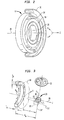
- static field magnet assembly 12 includes a plurality of cylindrical superconductive coils concentric with a central axis 26.
- the coils include an inner coil 28; middle coil 30; and outer coil 34 arranged concentrically with one another.
- a toroidal cryostat 36 encloses these coils.
- cryostat 36 defines an interior bore 38 extending through the innermost coil 28 and encompassing axis 26.
- Cryostat 36 is formed as a toroidal shell of a non-ferromagnetic material.
- the cryostat contains a coolant such as liquid helium or liquid nitrogen for maintaining the coils at superconducting temperatures.
- the coils are supported within the cryostat by internal supports (not shown).
- the wall of the cryostat is illustrated as a simple wall, in actual practice the cryostat desirably has one or more multiple wall structures with evacuated spaces between the walls.
- a structure is also referred to as a Dewar vessel and minimizes heat conduction to the contents of the cryostat, including the coils and the coolant.
- the cryostat may be an insulated enclosure which is cooled by means other than cryogenic fluids, such as by thermoelectric cooling or other conventional refrigeration systems. These systems can be used with high T c superconductors.
- the frame of reference and dimensioning system used to denote the dimensions of the individual coils are illustrated in Fig. 3 .
- the mean radius or R m and radial thickness T r of each coil are specified with respect to the central axis 26.
- the axial placement of each coil is given as the mean axial dimension A m of the coil, measured from the center point 22 of the magnetic resonance volume.
- the axial thickness T a of each coil is the dimension of the coil parallel to axis 26.
- the coil also defines a frontal plane 40 perpendicular to axis 26 at the forwardmost extent of the forwardmost coil in the static field magnet assembly.
- the coils of magnet 12 are connected to a conventional current source or static field actuator unit 33 ( Fig. 1 ).
- Unit 33 provides currents in the coils.
- the directions of current flow in the various coils are denoted as "positive” or “negative” symbols" as indicated by the arrows in Fig. 3 . These arbitrarily-selected directions of current flow are opposite to one another.
- the forward spacing distance f or distance from the frontal plane of the static field magnet assembly to the center point 22 of imaging volume 20 is also illustrated in Fig. 3 .
- the radial field curvature d 2 ⁇ B dX 2 is also relatively small and hence the field gradient in the radial direction is also relatively small.
- the magnet provides a field with a linear axial gradient and with very small radial gradients over a magnetic resonance volume or imaging volume 20 having axial extent of about 1 cm and having a diameter of about 3 cm.
- the volume 26 centered on point 22 at a forward spacing distance f from the frontal plane 40 of about 26 cm.
- the magnet is relatively small; the coils of the magnet can be accommodated in a cylinder approximately 78 cm in diameter and only about 14 cm thick.
- the small dimensions of the magnet dramatically reduce the cost and weight of the cryostat, and the cost of operation.
- the entire magnet may have a mass of less than about 500 kg and hence can be moved and positioned relative to the patient by a positioning device 23 of reasonable size.
- the gradient coil assembly 14 is depicted in Fig. 4 .
- the gradient coil assembly includes four windings 50, 52, 54 and 56 disposed around the common or central axis 26 of the static field magnet so that windings 50 and 52 form one diametrically opposed pair of windings and windings 54 and 56 form another diametrically opposed pair.
- the windings are generally planar and lie generally in plane perpendicular to the axis 26 of the static field magnet.
- Coils 50 and 52 are disposed along a first axis (labeled "X" in Fig.
- windings are formed from metallic ribbon having a small thickness dimension and a larger width dimension, the ribbon being wound on edge so that the width wise direction of the ribbon extends perpendicular to the plane of the winding and hence parallel to the axis 26.
- the ribbon may be about .016 inches (0.4 mm) thick and about 0.75 inches (2 cm) wide.
- Winding 50 includes an outer arcuate run 58 generally in the form of a circular arc concentric with axis 26, and also includes a pair of radial runs 60 and 62 extending generally radially inwardly from the ends of the arcuate run 58. These runs merge with one another adjacent central axis 26.
- Each of the other coils 52, 54 and 56 includes similar runs. Because the static field magnet inherently imposes a field gradient in the axial or Z direction, the gradient coil assembly used in this embodiment does not include a Z-direction gradient coil. However, if a Z-direction gradient coil is required, the same may be as a circular solenoid concentric with central axis 26.
- the windings are mounted in a non-ferromagnetic housing 57 which is provided with cooling passages (not shown) connected to a chiller or other source of coolant.
- the radius from the central axis 26 to the outside of the outer arcuate run of each winding desirably is about 25 cm or less so that the entire gradient coil assembly 14 and housing 57 is only about 50 cm diameter and about 3-4 cm thick.
- Housing 57 is disposed immediately in front of the static field magnet 12, i.e ., just forward of the cryostat 36 and as close as possible to the frontal plane 40 of the static field magnet. This leaves a large unoccupied region along the axis 26 between the gradient coil assembly and the imaging volume 20, so that the imaging volume can be positioned deep within the patient's body.
- the windings of the gradient coil assembly are connected to gradient driver 35.
- the power and control leads to the gradient coils may extend through the bore of cryostat 36.
- the gradient driver includes conventional D/A converters and amplifiers for receiving a desired gradient waveform in digital form from computer 29, converting the digital waveform to analog form and reproducing the analog waveform as currents in particular gradient coils controlled by the computer of the apparatus.
- the two windings of a pair may be energized so that the current flows in the outer arcuate runs of both windings in the opposite directions around the axis 26 of the static magnetic field assembly.
- windings 50 and 52 are energized with the current flows as indicated by arrow C in Fig. 4 , they will provide a field gradient in one direction in the X axis.
- the reverse current flows will produce a gradient in the opposite direction.
- Windings 54 and 56 can be actuated in the same manner so as to impose a field gradient in the Y-direction.
- the socket 19 at the forward or distal end of arm 17 includes a mechanical mounting element 62 ( Fig. 5 ) such as the tapered bore illustrated or any other conventional device for making a releasable mechanical interengagement.
- a mechanical mounting element 62 such as the tapered bore illustrated or any other conventional device for making a releasable mechanical interengagement.
- the tapered bore 62 may be replaced by a conventional vise, clamp, bolt joint or gripper, a multi-jawed chuck or a collet chuck.
- Mounting 19 also includes a coolant supply passage 63 and coolant withdrawal passage 64 which are connected to a conventional source (not shown) of a coolant such as chilled water.
- Mounting 19 further includes a multi-element electrical connector 66 which in turn is connected to the high intensity focused ultrasound driver 41 ( Fig. 1 ).
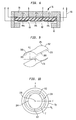
- the ultrasonic energy applicator 16 includes a disposable high intensity focused ultrasound unit 68.
- Unit 68 includes a substantially rigid frame 70, desirably formed from a polymeric material such as a polycarbonate or epoxy or other relatively rigid, high strength polymer.
- Frame 70 has a mounting element 72 rigidly connected thereto.
- the mounting element 72 is adapted to mate with the mounting receptacle 62 to form a rigid yet releasable connection.
- mounting element 72 may be a pin having a mating taper.
- Frame 70 defines a shallow dish generally in the form of a surface of revolution about an axis 74.
- each section 76 includes a rigid backing 78 such as a block of alumina, glass or rigid polymer.
- the section also includes a piezoelectric film 80 such as a polyvinylidene fluoride film of the type sold under the registered trademark Kynar by AMP Inc. of Harrisburg, Pennsylvania.
- a set of rear electrodes 82 is provided between film 80 and the backing 78, whereas a set of front electrodes 84 is provided on the front surface of film 80 facing away from backing 78.
- the front and rear electrodes are provided in matched pairs, so that the front electrode of each pair overlies the rear electrode of each pair.
- Electrodes 82(a) and 84(a) form a pair. These electrodes are aligned with one another and overlie with one another. Although only three pairs of electrodes are visible in Fig. 6 , the emitter section 76 may include numerous pairs of electrodes arranged in an array, as, for example, a three by three array incorporating nine pairs. A separate lead extends to each electrode. Electrodes 82 and 84 desirably are formed as thin conductive deposits on the surfaces of piezoelectric film 80 as, for example, by applying an electrically conductive ink on the surfaces of the piezoelectric layer or by processes such as sputtering or electroless plating, followed by electroplating. Individual leads 86 extend from each of the electrodes.
- Each pair of electrodes, and the portion of film 80 disposed between such pair of electrodes films forms an independently operable piezoelectric transducer.
- the region of the film between the electrodes can be made to expand or contract in the forward to rearward direction, i.e., in the direction towards the top and the bottom of the drawing as seen in Fig. 6 .
- the portion of the film between each pair of electrodes can be driven at ultrasonic frequencies.
- the particular section illustrated has the rear electrodes directly bonded to the surface of backing 78 so that the rear electrodes and the rear surface of the film are held rigidly.
- the thickness of the film 80 is desirable for the thickness of the film 80 to be approximately one-quarter of the wavelength of the ultrasonic vibrations. Typical operating frequencies are in a range of about 1 to 1.8 MHz, most commonly about 1.5 MHz, and the wavelength of the ultrasonic vibrations in the film is about 1 mm. Thus, where the rear surface of film is rigidly held to the backing as in the embodiment of Fig. 6 , the preferred thickness of film 80 is about 250 microns. In other embodiments, the film is supported away from the backing, so that the rear surface of the film is spaced from the backing and is free to vibrate. In these embodiments, the thickness of the film is approximately one half wavelength and desirably is about 500 microns or more.
- Protective layers such as a thin polymeric film or encapsulant may be provided over the front surfaces of film 80 and electrodes 84 to protect them from contact with the environment.
- a ring 90 formed from a rigid material such as alumina or polymeric material extends around the periphery of the film. Ring 90 is secured to support 78.
- Sections 76 are secured to the frame 70 ( Fig. 5 ).
- the individual leads associated with the various electrodes of all of the sections are connected through a common cable 92 to a multi-element plug 94 adapted to mate with multi-element socket 66 of mounting 19.
- the individual leads and cable 92 are constructed using standard techniques applicable to electrical structures for frequencies on the order of 1.5 MHz.
- the individual leads to each pair of electrodes desirably are provided as a coaxial, twisted pair or other transmission line suitable for high frequency operation.
- cable 92 may be formed as a so-called flex circuit capable of accommodating a large number of transmission lines.
- the individual sections 76 are mounted in the frame so that the forward or active surface (the surface bearing forward electrodes 84) faces forwardly, i.e., in the downward direction as seen in Fig. 6 .
- the front faces of the elements are directed generally inwardly towards an applicator axis 74 as well as forwardly.
- the individual elements of the sections thus constitute a phased array of ultrasonic emitters.
- the energy emitted by the various ultrasonic emitters can be focused into a small focal spot 94.
- the array is optimized to provide a spot having dimensions on the order of about 2-3 mm.
- the array desirably provides an ultrasonic intensity of approximately 1500 watts/cm 2 at the focal spot to enable heating of tissues at the focal spot from about 37°C to about 60-80°C in less than one second. Such rapid heating capability greatly reduces treatement time. Typically, approximately 1500 watts of electrical power must be applied to the array to yield about 500 watts of ultrasonic emission.
- the focal spot can be provided over a range of positions within energy application volume 21. The focal spot can be moved within energy application volume 21 by varying the phases and amplitudes of the driving signals applied to the individual ultrasonic emitting elements, i.e., by varying the phases and amplitudes of the electrical signals sent to the various electrodes 82 and 84.
- the array is arranged to provide a focal length of about 20 cm, i.e., the distance from the array to the center of the energy application volume 21 along axis 74 is about 20 cm or more. Typically, the array has a diameter of about 15 cm.
- the individual sections may be flat as discussed above, or else may be curved. Curved sections may have a generally spherical shapes, or else may have different radii of curvature along differenct axes. The sections may be smaller or larger than those discussed above.
- each section may include only one element.
- the entire array can be formed as a single curved section and the backing of such section can serve as the frame 70.
- the individual emitting elements within the array, and the individual emitting elements within a single section may have different shapes and sizes.
- the emitting elements may have square or other polygonal shapes, or may have circular or elliptical.
- the design of ultrasonic phased arrays, and computer simulations of such arrays are disclosed in Ebbini, et al., Optimization of the Intensity Gain of Multiple-Focused Phased Array Heating Patterns, Int. J. Hyperthermia, 1991, Vol. 7, #6, pp.
- the disposable unit 68 further includes a flexible water-filled bag 98 attached to the frame 70 so that the ultrasonic emitting elements on the frame are coupled to the water for transmission of ultrasonic emissions into the water.
- the bag may be attached to the periphery of frame 70.
- Bag 98 may be formed from a thin polymeric film.
- the surface of the bag which will lie against the subject's body in use may be formed from a polyethylene terepthalate film, whereas the other walls of the bag may be formed from a polyethylene film.
- the water within bag 98 is substantially free of dissolved air.
- the film constituting bag 98 is air-permeable, it is preferably to remove air from the water during manufacture of the disposable unit, and to supply the disposable unit vacuum-packed in an outer container which is air-impermeable.
- the disposable unit also includes a coolant passage 100 having connectors 102 and 104 adapted to fit the coolant passages 63 and 64 of mounting 19.
- the HIFU driver 41 ( Fig. 1 ) includes conventional components for providing the required driving signals as commanded by computer 29.
- Driver 41 is connected to receptacle 66 so that when cable 92 is connected to the receptacle, the HIFU driver is connected to all of the individual electrodes 82 and 84 of the piezoelectric elements.
- a flexible skirt 106 is mounted permanently on the distal end of arm 17 so that it surrounds mounting 19 and so that the skirt projects downwardly away from arm 17.
- the circular loop antenna 37 is mounted to the edge of the skirt remote from the arm.
- RF transceiver 39 is connected to loop antenna 37.
- the transceiver typically includes a relatively high powered transmitting section and a sensitive receiver, together with devices for disabling the receiver when the transmitter is actuated and vice versa.
- the RF antenna and transceiver desirably is tunable over a range of frequencies corresponding to the range of Larmor frequencies or magnetic resonance frequencies for protons subjected to the magnetic fields of the static field magnet.
- transmitter and receiver are provided with variable components such as variable capacitors or capacitor switching networks for adjusting or tuning to match the Larmor frequencies at particular locations within the imaging volume.
- the disposable HIFU unit 68 is received within skirt 106 and engaged with mounting 19 so that the HIFU unit is held physically on arm 17 with the axis 74 of the HIFU unit projecting generally downwardly and hence transverse to the central axis 26 of the static field magnet. In this condition, the energy application volume 21 overlaps the imaging volume 20. Moreover, the HIFU unit is rigidly held at a fixed position and orientation with respect to the static field magnet.
- the arm 17 desirably is positioned so that the water bag 98 is engaged with the patient's skin. Ultrasonic vibrations may be transmitted from the piezoelectric elements of section 76 through the water within a bag 98 and through the bag itself into the patient with minimal losses.
- Loop antenna 37 is disposed in or near the patient's body surface.
- the axis of the loop antenna is close to or coincident with the axis 74 of the HIFU unit. Stated another way, the axis of loop antenna 108 is transverse to the central axis 26 of the static field magnet, and hence transverse to the magnetic field vector.
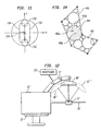
- Control console 13 includes a conventional monitor 110 such as a cathode ray tube or flat panel display, as well as manual input devices including a joystick 112 ( Fig. 7 ) and a rotatable dial 114.
- Joystick 112 desirably is a so-called “force-feedback" joystick, equipped with conventional devices for applying forces to the joystick responsive to commands received by the joystick assembly.
- One suitable joystick is sold under the trademark Sidewinder Force Feedback Pro by Microsoft Corporation.
- Dial 114 may be incorporated in the joystick assembly.
- the joystick is also equipped with a push button 115.
- the control console further includes additional command and control switches 116, and may further include a keyboard (not shown). All of these elements are linked to control computer 29.
- Control computer 29 ( Fig. 1 ) desirably is a conventional general purpose digital computer such as a computer of the type commonly referred to as a "workstation” and includes conventional elements such as microprocessor and data transfer bus (not shown).
- the control computer further includes memory elements 118, which may incorporate conventional devices such as dynamic random access memory, flash memory or the like and mass storage such as magnetic disc optional storage.
- the data bus of the control computer is linked through a conventional interfacing element (not shown) to the elements of the control console; to the positioner interface; to the static field application unit 33 and gradient driver 34 and to the HIFU driver 41 and RF transceiver 39.
- the control computer program desirably is arranged to display a menu of operating modes as discussed below on monitor 110, so that the operator can select the desired operating mode by activating switches 116.
- a patient P ( Fig. 1 ) is supported on a bed 24.
- Mobile unit 10 is moved on castors 27 into a position such that the magnetic resonance volume 20 and energy application volume 21 are approximately aligned with the organ 120 of the patient which requires treatment.
- the water-filled bag of the HIFU unit is engaged with the patient's skin and the RF antenna 37 is positioned around the bag.
- the operator actuates the computer to perform a preliminary magnetic resonance imaging operation.
- the static field magnet is operated to apply the magnetic field within magnetic resonance volume 20 and the gradient coils and RF transceiver are operated to apply RF signals and magnetic field gradients in a conventional magnetic resonance imaging sequence.
- Transceiver 39 and antenna 37 are tuned to a frequency corresponding to the Larmor frequency by atomic nuclei, preferably protons at the magnetic field prevailing in a particular thin slice S ( Fig. 3 ) within magnetic resonance volume 20. Because the magnetic field provided by the static field magnet incorporates a gradient in the axial or Z direction and because the Larmor frequency of the nuclei varies proportionally with the prevailing magnetic field, the resonant or Larmor frequency varies with distance along the Z axis. In the conventional manner, the transceiver is actuated to send a pulse of RF energy into the subject, thereby exciting the nuclei within the slice S where the resonant frequency of the nuclei matches the frequency of the RF signal.
- the gradient coils are actuated to apply magnetic field gradients in the X and Y directions, transverse to the axial or Z direction. This causes the signals from the nucleii at various positions within the slice to vary in frequency and phase in a known manner.
- the RF transceiver is actuated to receive the magnetic resonance signals and to digitize the same and supply the digitized signals to control computer 29. This process is repeated with variation of the X and Y gradients in known fashion.
- the signals acquired by transceiver 39 are stored in the memory of the computer.
- the control computer reconstructs an image of the subject's tissues within slice S. This procedure can be repeated again using different radio frequencies so as to select different slices within magnetic resonance volume 20.
- the resulting data provides a three dimensional image of that portion of the subject located within the magnetic resonance volume.
- the image is displayed on monitor 110.
- the operator can observe the image and determine whether the region of the subject to be treated is centered in the field of view. As depicted in Fig. 7 , the image may be displayed as a pair of orthogonal sectional views through the subject. If the region requiring treatment is not centered in the field of view, the operator can enter a command to the control computer, to enter a repositioning mode. In this mode, the computer accepts input from the joystick 112 and dial 114. Thus, depending upon the commands received from the command input element 116, the control computer will interpret input from joystick 112 and turn wheel 114 as commanding movement of chassis 15 either in translation or in rotation.
- the computer may be set to accept translation inputs and to treat joystick movements in a direction X' as commanding upward translation of the chassis; joystick movement in a direction Y' as commanding horizontal translation and movement of turn wheel 114 as commanding forward and backward or Z-direction translation of the chassis.
- the computer may treat joystick movements in the X' direction as commanding tilting movements about a horizontal axis transverse to the central axis 26 and joystick movements in the transverse direction Y' as commanding rotation of the chassis around a vertical axis.
- the imaging procedure is repeated, and the operator continues to monitor the displayed images.
- the operator can use the images to diagnose conditions within the body as, for example, to detect lesions in the body which require treatment.
- the operator issues a further signal to the command input element 116 which causes the control computer to lock the position and thereby fix chassis 15, the static field magnet, the HIFU unit and other elements in position.
- the local magnetic resonance frame of reference established by the static field magnet and associated components is fixed.
- the computer treats inputs from joystick 112 and dial 114 as commanding movement of a theoretical aim point in this fixed local magnetic frame of reference.
- the position of the theoretical aim point changes in the X and Y directions, respectively, whereas rotation of dial 114 causes movement of the theoretical aim point in the Z direction.
- a cursor 124 is displayed within the images on monitor 110 in a position corresponding to the position of the theoretical aim point. Using the dial and the joystick, the operator moves the cursor 124 to a series of vertex points 126.
- the operator selects these vertex points so that they constitute to be vertexes of a polyhedron, or set of polyhedrons encompassing the treatment zone to be subjected to heating.
- the image shows a lesion L.
- the vertex points 126 are selected to form a pair of truncated pyramids 128a and 128b which cooperatively encompass the lesion L.
- the computer records the theoretical aim point corresponding to each such vertex in memory 118.
- the computer further generates a wire-frame image of the polyhedron and vertex on display screen 110 and superposes this image over the image of the subject's tissues derived from the magnetic resonance information.
- the computer actuates the energy application or HIFU unit 16 to apply focused ultrasound at a spot 94 at a location corresponding to the location of one of the vertices 126.
- the computer commands the HIFU driver to apply a relatively small "subthreshold" dose of energy to the tissues in the spot 94. That is, the amount of energy supplied by the HIFU driver is selected so that the heat applied in this operation will not destroy or alter the tissue.
- the tissue may be heated from normal body temperature (37°C) to about 40°C.
- the heated spot should be positioned exactly at the location commanded by computer 29.
- the imaging procedure is repeated using a magnetic resonance sequence which is temperature sensitive, such as a T 1 weighted sequence, so that the displayed image includes a spot 94' depicting the heated spot.
- the operator then actuates the joystick 116 and dial 114 to position cursor 124 over the spot 94 and provides a further control input for push button 115.
- the computer thus records the location corresponding to the position of the cursor as the position of the actual heated spot.
- the computer then subtracts the coordinates of the actual position from the corresponding coordinates of the commanded position. The result is a correction vector. In the succeeding operations, the computer will add this correction vector to all new commanded positions so as to provide a corrected commanded position which will result in heating at the true, commanded location.
- the computer executes a test point sequence.
- the computer commands the HIFU unit to apply a series of subthreshold doses at each vertex 126, so that each vertex serves as a test point.
- the computer commands the HIFU unit to apply a particular amount of energy to the heated spot of the vertex or test point.
- the magnetic resonance apparatus is actuated to determine the temperature at each test point before and after application of each subthreshold dose.
- the computer records the amount of energy applied by the HIFU unit (typically measured as input power supplied to the HIFU unit) and the resulting temperatures rise in memory 118. In this regard, the magnetic resonance imaging apparatus need not complete an entire imaging sequence to measure the temperature.
- the magnetic resonance apparatus may be actuated in a known manner to acquire magnetic resonance signals from a signal volume element or "voxel" at the test point being heated.
- So-called "sensitive-point” magnetic resonance methods are described in Mansfield and Morris, NMR Imaging in Biomedicine, 1982, p. 98 .
- the computer can monitor the temperature of the subject's tissues at the vertex or test point 126 being heated. From the recorded applied energies and temperature increases, the computer calculates a calibration curve of applied energy versus temperature rise. In the simplest case, the computer calculates only the slopes of a linear plot of temperature rise versus applied energy.
- the operator actuates the computer to enter a treatment mode.
- the computer commands the HIFU unit to apply energy to the subject's tissues within the treatment volumes or polyhedron 128.
- the computer commands the HIFU unit to apply a therapeutic dose sufficient to heat the tissue at each treatment location to a sufficient degree to perform the required treatment.
- the treatment dose is selected to bring the temperature of the tissue above about 43°C, and typically to about 60°-80°C.
- Other treatments such as to enhance the effect of drugs or radiation therapy, typically use lower temperatures.
- the amount of energy to be applied at each treatment location is selected based on an interpolated calibration curve.
- the calibration curve for each treatment location is computed by linear interpolation among the calibration curves for the test point vertices of the polyhedral treatment volume.
- the computer sets S ave equal to the slope at that test point or vertex. For example, treatment location 136a is close to test point or vertex 126a and far from test point or vertex 126b.
- the computer will set the slope of the energy versus temperature rise plot at treatment location 136a close to the slope at test point 126a.
- the computer automatically selects new treatment locations, calculates the slope at the newly selected treatment location and applies the appropriate therapeutic dose until therapeutic doses have been applied at all possible treatment locations within the treatment volume defined by polyhedron 128a and 128b. Desirably, each treatment location is brought to the desired temperature rapidly, typically in one second or less. Thus, the system can complete the treatment throughout the treatment volume rapidly.
- the computer may periodically acquire magnetic resonance information from one or more voxels within the treatment volume and monitor the temperature in such voxel based on this magnetic resonance information.
- the computer can actuate the magnetic resonance apparatus to conduct a full magnetic resonance imaging sequence using a temperature-sensitive imaging protocol and display an image showing the heated region and the surrounding tissues.
- the operator may command the system to acquire a new magnetic resonance image after completion of the entire treatment so that the effect of the treatment can be assessed.
- the operator moves the theoretical aim point applicator using the joystick 112 and dial 114 so as to move the cursor 124 ( Fig. 8 ) about in the displayed image in the manner discussed above, and actuates button 115 to mark vertices 126'.
- the computer is instructed to record these vertices as vertexes of an avoidance zone rather than as vertexes of the treatment volume.
- the computer generates a wire frame image of polyhedra 128' with vertexes corresponding to vertexes 126'. The operator selects vertices 126' and thus selects the tissues encompassed by the avoidance zone by observing the displayed image.
- the image of a sensitive structure such as the urethra U is shown on the display monitor 110.
- the operator has established the avoidance zone so as to encompass the urethra.
- the computer records the boundaries of these polyhedra as boundaries of the avoidance zone.
- the operator manually selects test points 129 outside of the avoidance zone and performs the calibrations step discussed above, so as to calibrate the system for errors in aim of the HIFU unit and to arrive at a applied dose to heating calibration curve for each test point 129.
- the test points desirably are selected so that they are at or near the periphery of the lesion L' to be treated.
- the operator then commands to enter a manual ablation mode.
- the computer responds to a manual operation of the joystick 112 and dial 114 as commands to move the aim point of the HIFU unit, and the computer responds to manual actuation of the push button on the joystick as a command to apply a therapeutic dose at the current aim point.
- the computer responds to manual actuation of the push button on the joystick as a command to apply a therapeutic dose at the current aim point.
- the computer responds to manual actuation of the push button on the joystick as a command to apply a therapeutic dose at the current aim point.
- the theoretical aim point is within the lesion.
- Application of a therapeutic dose will heat the tissues at the point within the subject's body corresponding to the aim point.
- the dose can be selected automatically based upon the dose to heating calibration curves calculated as aforesaid or can be selected manually.
- the system will prevent him from doing so. Thus, if the aim point is close to the avoidance zone, and if the operator commands the system to move the aim point into the avoidance zone, the system will not do so. Instead, the system will issue a warning signal by providing force feedback through the control. For example, with the cursor in the position indicated at 124' in Fig. 8 , upward movement in the X direction will bring the cursor into the avoidance zone. If the operator attempts to move the joystick 112 upwardly in the X' direction and thus moves the cursor 124' upwardly, the system will apply a countervailing force feedback to resist this motion. Force feedback provides a uniquely intuitive warning to the operator. However, other forms of warning signals may be employed. For example, the system may display an alphanumeric warning on the monitor 110, or may cause the monitor display to flash or may illuminate the cursor in a distinct color. Audible warnings may also be employed.
- the computer allows the operator to move the aim point into the avoidance zone, but inhibits application of a therapeutic dose while the aim point is within the avoidance zone.
- the system can display any form of tactile visual or audible warning before the operator attempts to apply a therapeutic dose while the aim point is in the avoidance zone.
- the magnetic resonance information was acquired in only a single magnetic resonance volume.
- the system can collect magnetic resonance information over a plurality of different magnetic resonance volumes.
- the static field magnets and related components can be swung about a vertical axis so as to swing the central axis 26' to a new orientation and move the magnetic resonance volume to a new position indicated in broken lines at 20'.
- a different local magnetic resonance frame of reference is established by moving the chassis and the static field magnets and related components mounted thereto.
- the computer records movement of the chassis between positions. Therefore, each new local magnetic resonance frame of reference is in a known position and orientation relative to all of the preceding local magnetic resonance frames of reference.
- Magnetic resonance information gathered in all of the various frames of reference can be transformed into a single, common working frame of reference.
- the system can display an image of the subject encompassing features in a relatively large region.
- the frame of reference of the HIFU unit remains fixed with respect to the frame of reference of the static field magnet.
- the system can be operated to treat the subject while the chassis is in one position and then moved to a new position to perform additional treatments on tissues at other locations within the subject's body.
- the computer constructs a mosaic of the relatively small magnetic resonance images so that the mosaic as a whole encompasses a large region of the subject.
- the gradient coils may have shapes other than the shapes discussed above with reference to Fig. 4 .
- the X and Y gradient coils may be circular.
- a further coil or coils may be provided.
- the Z gradient coil may include a circular solenoid coaxial with the central axis of the static field magnet.
- the X-gradient coils may be formed as a pair of opposed saddle-shaped coils 202 ( Figs. 9 and 10 ) arranged on opposite sides of the central axis 226 of the static field magnet.
- each X-gradient coil 202 has elongated runs 203 extending generally codirectionally with the central axis, and arcuate runs 205 extending partially around the central axis. The arcuate runs are spaced apart from one another in the direction along the X axis of the magnetic resonance frame of reference.
- the gradient coil assembly may include a similar pair of saddle-shaped coils 204 spaced apart from one another in the Y direction.
- the arcuate runs of the X and Y gradient coils at the forward ends of the coils are disposed forwardly of the cryostat, whereas the elongated straight runs may extend rearwardly through the central bore of the cryostat.
- the X and Y gradient coils partially overlap one another as seen in end view along the central axis 226.
- the elongated runs of the saddle-shaped coils may extend on the outside of the cryostat.
- the X-direction gradient coils 210 are elongated in the Y direction, so that these coils can impose an X direction gradient throughout an elongated imaging region having a relatively large dimension in the Y direction.
- the Y-direction gradient coils 212 are spaced relatively far apart, so that these coils can also apply the Y direction gradient over the same elongated imaging region.
- the gradient coils may be of different sizes.
- the X-direction gradient coils 212 may be of different dimensions.
- the HIFU unit may have a fixed focus, and the arm 17 or mounting 19 ( Fig. 1 ) may be articulated so that the focus of the ultrasound can be moved by turning the axis 74 of the HIFU unit 16 or moving the HIFU unit relative to the chassis 15.
- an articulated arm 17' or mounting 19' supporting the HIFU unit 16' ( Fig. 12 ) can be combined with the phased array.
- the articulated arm 17' has a positioning device 23' associated with is so that the position and orientation of the HIFU unit 16' relative to chassis 15' can be varied.
- the position and orientation of the HIFU unit 16' in the local magnetic frame of reference defined by the static field magnet remain known.
- the control computer can display a marker on the image of the subject which indicates the location of the center of the energy application zone 21', so that the operator can move the energy application zone to the desired position.
- the ultrasonic transducers may be mounted on a deformable resilient flange and the flange may be selectively deformed by an actuator to vary the focus of the ultrasonic transducers and thus adjust the focus to the desired location.
- each transducer can be pivotally mounted on the instrument frame, and the pivotal mountings can be linked to one another so that the transducers pivot towards and away from the axis of the HIFU unit in unison.
- the HIFU unit may include ultrasonic transducers disposed in an array coaxial with the central axis of the static field magnet, such as an annular arrangement around the forward side of the magnet assembly.
- the ultrasonic axis is coaxial with of the central axis of the magnet.
- the ultrasonic transducers may be mounted on a deformable flange or movable element so that the focus of the ultrasonic energy can be adjusted.
- the ultrasonic transducers or HIFU unit can be replaced by other devices for applying energy so as to heat tissue at a spot within the body.
- a system for applying focused radiofrequency (RF) energy can be utilized.
- the RF system can be mounted on the along with the magnetic resonance components.
- the focused RF energy may be provided by the same transmitter and antenna used for magnetic resonance operations.
- the energy applying device moves with the magnet relative to the patient as the positioning system moves the instrument chassis.
- an energy applying device 316 is mounted on one positioning system 318 whereas the magnetic resonance apparatus 312, including the static field magnet, is mounted on a separate positioning system 323. Both of these positioning systems are supported by rails 325 mounted overhead, so that the operator can move the components within the room.
- the energy applying device is positioned relative to the subject in a separate step from the step of positioning of the magnetic resonance device.
- the energy applying device is positioned so that it can heat tissues in an energy application zone 321 within the field of view of the magnetic resonance device, and in alignment with the body structure to be treated.
- the magnetic resonance device may be used to aid this positioning if the heating device is actuated during the positioning stage, so that the spot heated by the heating device can be located in the magnetic resonance image or otherwise detected by the magnetic resonance device.
- the computer may be arranged to display an indication of the center point of the energy application zone superposed on the image of the subject.
- the actuation used during the positioning step preferably consists of subthreshold doses which heat the tissue only slightly, and does not permanently damage the tissue.
- positioning systems 323 and 318 are arranged to track the position and orientation of the magnetic resonance apparatus 312 and energy applicator 316 in a common frame of reference, such as in the frame of reference of rails 325.
- the steps of positioning of the magnetic resonance apparatus 312 and the energy applicator 316 in alignment with one another, with energy application zone 321 intersecting magnetic resonance volume 320 can be performed partially or entirely with based on data supplied by the positioning systems.
- the positioning system or systems may be registered with fiducial markers or anatomical landmarks on the patient, and may be registered with previously-acquired image data, such as MRI or CT data defining a three-dimensional image of the subject.
- a probe 330 may be connected to a position detector 332 adapted to provide the position of the probe tip in the frame of reference of magnetic resonance device 312 (the local magnetic frame of reference), or in another frame of reference having a known relationship to the local magnetic frame of reference.
- the previously-acquired image data includes images 332' of identifiable points 332 on the subject's body, which may be naturally-occurring anatomical features such as prominent bony protruberances or fiducial markers attached to the subject before acquisition of the image data.
- the operator By touching the tip of probe 330 to identifiable points 332, the operator inputs the locations of these points in the local magnetic frame of reference to the control computer.
- the operator By manipulating a cursor on a monitor displaying the previously-acquired image until the cursor is aligned with the identifiable points, the operator inputs the locations of these points in the frame of reference of the previously-acquired image data.
- the computer Once the computer has the locations of the same points in both frames of reference, it can derive the transform between the two frames of reference using known techniques.
- the previously-acquired image data can be used to supplement the data acquired by the magnetic resonance unit 312.
- representations of the aim points of these devices can be depicted on a display showing the previously acquired image, and these can be moved by moving the devices relative to the patient until the aim points are depicted as aligned on the region to be treated.
- the same approach can be used to align a single instrument incorporating both MR and heating capabilities.
- the movable magnetic resonance device is not used to acquire an image of the subject. Rather, the movable magnetic resonance device is used to acquire magnetic resonance data only in a single voxel at a known location in the local magnetic resonance frame of reference so as to monitor the heating process.
- the movable magnetic resonance apparatus may be used to monitor temperature in a single voxel aligned with the focal spot of the energy-applying device, during application of test doses or during application of therapeutic doses.
- the operations discussed above, such as defining treatment volumes or avoidance zones, may be performed in substantially the same manner; the image displayed to the operator is based on the previously-acquired image data.
- a marker on the subject may be tracked so as to track and compensate for movement of the subject.
- Such a marker and compensation scheme also may be used where the movable magnetic resonance device is used to acquire images.
- the magnet of the magnetic resonance apparatus is a single-sided, movable magnet.
- Other movable magnets can be used.
- certain movable superconducting magnets have been used for magnetic resonance imaging. These magnets have dual coils mounted to a movable frame, so that the subject is disposed between the coils.
- aspects of the invention such as the use of test points, treatment volumes and avoidance zones can be practiced even when the procedure is conducted within a conventional fixed magnetic resonance magnet.
- the focal spot of the HIFU unit or other energy applicator may be made as small as possible so that the treatment can be precisely applied.
- the energy applying device is still focused on a relatively small focal spot.
- the focal spot is swept over a larger "pseudo-focal region" (hereinafter "PFR") while applying energy.
- PFR typically is of larger size than the focal region.
- the PFR may have dimensions on the order of 1cm or so.
- the sweeping process is performed so as to heat the entire PFR, or a portion of the PFR, to or above the desired temperature. Most preferably, that portion of the PFR which reaches the desired temperature reaches such temperature at about the same time.
- the focal spot moves throughout the PFR either in a repetitive pattern or in a pseudorandom pattern so as to heat different locations in the PFR at successive times.
- the locations heated at successive times need not be contiguous or even adjacent to one another.
- the focal spot may skip from location to location within the PFR, so that the focal spot is located at widely-separated points within the PFR at successive times.
- the focal spot may be moved in a raster-like pattern 404 throughout a PFR 402a so that neighboring points are heated at successive times.
- the average power applied to each point within the PFR may be controlled by controlling the duty cycle at each location.
- the term "duty cycle" refers to the proportion of the entire heating time for the PFR that the energy is applied to at the particular point. For example, if energy is applied to the PFR by sweeping a focal region throughout the PFR for a period of five minutes, and the focal spot encompasses a particular location for a total of five seconds during that five minute period, then the duty cycle at that spot is 1/60 or about 1.6%.
- the duty cycle need not by uniform within the PFR.
- the center of the PFR may be treated with a lower duty cycle than the outer portions of the PFR so as to compensate for the more rapid heat loss from the outer portions to the surrounding tissues.
- the duty cycle at location 406b may be lower than the duty cycle at location 406a.
- the average rate of power application to various points within the PFR can be made nonuniform by varying the power applied to the focal spot so that the power level is different for different locations of the focal spot within the PFR.
- the size of the focal spot can be varied, by adjusting the HIFU unit or other energy-applying device, so as to vary the power density (watts/cm 3 of tissue within the focal spot) as the focal region moves.
- a PFR may have a wide variety of shapes as, for example, spherical, elliptical, rod-like, generally rectangular or the like.
- shape of the PFR is selected so that the PFR is a "simply-connected" region.
- the term “simply-connected” refers to a region such that, for any two points within the region, a straight line connecting the two points will be disposed entirely within the region.
- the aforementioned shapes are simply connected.
- a toroid is not simply-connected.
- the energy input throughout the PFR can be calculated by monitoring the temperature at various locations within the PFR as, for example, by magnetic resonance temperature measurements at a point or points within a PFR or, alternatively, by capturing a continuous MRI map or image, which may be visually displayed.
- the heating process can be controlled manually or automatically so as to vary the amount of energy input to various regions of the PFR and terminate the heating process when the desired threshold temperature is reached in all regions of the PFR.
- the heating process can be terminated selectively in different regions of the PFR as each region reaches the desired temperature. For example, where the desired temperature is a threshold temperature sufficient to kill the tissue, the heating process is terminated as each region of the PFR reaches the threshold temperature.
- the heating process can be controlled by prediction using test points in the manner discussed above.
- the position of the PFR can be controlled in substantially the same way as discussed above for control of the focal spot.
- the computer can be controlled to inhibit energy application to any PFR which overlaps with the avoidance regions.
- the operator controlling the process, or the computer may select one or more PFRs having shapes which fit well with the regions to be ablated.
- the operator has defined an a treatment volume 400 encompassing the region of the subject to be treated.
- the operator can then define a set of PFRs 402 which fill the treatment volume.
- the operator can enter the boundaries of the PFRs into the computer in the same manner as the operator enters the boundaries of the treatment volume.
- the computer then actuates the energy applicator to heat each PFR.
Claims (4)
- Applicateur d'ultrasons focalisés de forte intensité scellé jetable (16) comportant un cadre (70), une pluralité d'émetteurs ultrasoniques (76) montés sur ledit cadre (70) et formant un réseau de transducteurs, et un sac (98) contenant un fluide sensiblement exempt d'air, dans lequel ledit sac (98) est relié en permanence audit cadre (70), ledit sac étant flexible de sorte que ledit sac peut être placé entre le réseau de transducteurs et une surface du corps d'un patient, lesdits émetteurs (76) étant couplés audit fluide pour une transmission de vibrations ultrasoniques par l'intermédiaire dudit fluide.
- Applicateur selon la revendication 1 comportant en outre un boîtier étanche à l'air pouvant être retiré et entourant le cadre et le sac.
- Applicateur selon la revendication 1, dans lequel ledit sac (98) fait saillie depuis ledit cadre (70).
- Applicateur selon la revendication 1, dans lequel ledit cadre (70), ledit sac (98), ledit fluide et lesdits émetteurs (76) constituent une unité reliée en permanence, ladite unité étant adaptée pour une connexion amovible à un appareil d'actionnement par ultrasons.
Applications Claiming Priority (11)
| Application Number | Priority Date | Filing Date | Title |
|---|---|---|---|
| US4752697P | 1997-05-23 | 1997-05-23 | |
| US47526P | 1997-05-23 | ||
| US5412497P | 1997-07-28 | 1997-07-28 | |
| US54124P | 1997-07-28 | ||
| US6251897P | 1997-10-17 | 1997-10-17 | |
| US62518P | 1997-10-17 | ||
| US7447498P | 1998-02-12 | 1998-02-12 | |
| US74474P | 1998-02-12 | ||
| US7532498P | 1998-02-20 | 1998-02-20 | |
| US75324P | 1998-02-20 | ||
| PCT/US1998/010623 WO1998052465A1 (fr) | 1997-05-23 | 1998-05-22 | Unite therapeutique guidee par imagerie par resonance magnetique (irm) et procede associe |
Publications (3)
| Publication Number | Publication Date |
|---|---|
| EP0998217A1 EP0998217A1 (fr) | 2000-05-10 |
| EP0998217A4 EP0998217A4 (fr) | 2001-08-22 |
| EP0998217B1 true EP0998217B1 (fr) | 2009-01-07 |
Family
ID=27535001
Family Applications (1)
| Application Number | Title | Priority Date | Filing Date |
|---|---|---|---|
| EP98928831A Expired - Lifetime EP0998217B1 (fr) | 1997-05-23 | 1998-05-22 | Applicateur jetable d'ultrasons haute intensite a faisceau concentre |
Country Status (8)
| Country | Link |
|---|---|
| US (4) | US6128522A (fr) |
| EP (1) | EP0998217B1 (fr) |
| JP (1) | JP2002505596A (fr) |
| CN (1) | CN1230120C (fr) |
| AT (1) | ATE419789T1 (fr) |
| AU (1) | AU8053598A (fr) |
| DE (1) | DE69840444D1 (fr) |
| WO (1) | WO1998052465A1 (fr) |
Cited By (1)
| Publication number | Priority date | Publication date | Assignee | Title |
|---|---|---|---|---|
| US11801401B2 (en) | 2009-12-28 | 2023-10-31 | Profound Medical Inc. | High intensity focused ultrasound transducer optimization |
Families Citing this family (381)
| Publication number | Priority date | Publication date | Assignee | Title |
|---|---|---|---|---|
| US6084587A (en) * | 1996-08-02 | 2000-07-04 | Sensable Technologies, Inc. | Method and apparatus for generating and interfacing with a haptic virtual reality environment |
| JPH11267133A (ja) * | 1998-03-25 | 1999-10-05 | Olympus Optical Co Ltd | 治療装置 |
| US6421048B1 (en) | 1998-07-17 | 2002-07-16 | Sensable Technologies, Inc. | Systems and methods for interacting with virtual objects in a haptic virtual reality environment |
| US6552722B1 (en) * | 1998-07-17 | 2003-04-22 | Sensable Technologies, Inc. | Systems and methods for sculpting virtual objects in a haptic virtual reality environment |
| JP2000107151A (ja) * | 1998-09-30 | 2000-04-18 | Toshiba Corp | 磁気共鳴イメージング装置 |
| US8244370B2 (en) | 2001-04-13 | 2012-08-14 | Greatbatch Ltd. | Band stop filter employing a capacitor and an inductor tank circuit to enhance MRI compatibility of active medical devices |
| US7844319B2 (en) | 1998-11-04 | 2010-11-30 | Susil Robert C | Systems and methods for magnetic-resonance-guided interventional procedures |
| US6701176B1 (en) | 1998-11-04 | 2004-03-02 | Johns Hopkins University School Of Medicine | Magnetic-resonance-guided imaging, electrophysiology, and ablation |
| US6246896B1 (en) * | 1998-11-24 | 2001-06-12 | General Electric Company | MRI guided ablation system |
| US6208142B1 (en) * | 1998-12-07 | 2001-03-27 | Transurgical, Inc. | Magnetic resonance apparatus and methods with shim adjustment |
| US6278351B1 (en) | 1999-01-11 | 2001-08-21 | Transurgical, Inc. | Multi-coil MRI magnet |
| IT1309458B1 (it) * | 1999-02-10 | 2002-01-23 | Paramed S R L | Apparato per tomografo a risonanza magnetica. |
| US6508774B1 (en) | 1999-03-09 | 2003-01-21 | Transurgical, Inc. | Hifu applications with feedback control |
| US6591127B1 (en) * | 1999-03-15 | 2003-07-08 | General Electric Company | Integrated multi-modality imaging system and method |
| US6492762B1 (en) | 1999-03-22 | 2002-12-10 | Transurgical, Inc. | Ultrasonic transducer, transducer array, and fabrication method |
| US6422552B1 (en) * | 1999-07-26 | 2002-07-23 | Heidelberger Druckmaschinen Ag | Movable folders and former board arrangement |
| JP3848572B2 (ja) | 1999-09-10 | 2006-11-22 | プロリズム,インコーポレイテッド | 解剖学的組織を閉塞するための装置 |
| FR2798296B1 (fr) * | 1999-09-13 | 2002-05-31 | Centre Nat Rech Scient | Ensemble de traitement thermique de tissus biologiques et procede de mise en oeuvre de cet ensemble |
| US7520856B2 (en) | 1999-09-17 | 2009-04-21 | University Of Washington | Image guided high intensity focused ultrasound device for therapy in obstetrics and gynecology |
| US7510536B2 (en) * | 1999-09-17 | 2009-03-31 | University Of Washington | Ultrasound guided high intensity focused ultrasound treatment of nerves |
| US7019610B2 (en) * | 2002-01-23 | 2006-03-28 | Stereotaxis, Inc. | Magnetic navigation system |
| US7313429B2 (en) | 2002-01-23 | 2007-12-25 | Stereotaxis, Inc. | Rotating and pivoting magnet for magnetic navigation |
| EP1229839A4 (fr) | 1999-10-25 | 2005-12-07 | Therus Corp | Utilisation d'ultrason focalise destinee a l'etancheite vasculaire |
| US6626855B1 (en) | 1999-11-26 | 2003-09-30 | Therus Corpoation | Controlled high efficiency lesion formation using high intensity ultrasound |
| WO2001050156A1 (fr) | 1999-12-30 | 2001-07-12 | Transurgical, Inc. | Fonctionnement associe d'un appareil a irm et d'un equipement electronique |
| US6595934B1 (en) * | 2000-01-19 | 2003-07-22 | Medtronic Xomed, Inc. | Methods of skin rejuvenation using high intensity focused ultrasound to form an ablated tissue area containing a plurality of lesions |
| US8221402B2 (en) * | 2000-01-19 | 2012-07-17 | Medtronic, Inc. | Method for guiding a medical device |
| US8241274B2 (en) | 2000-01-19 | 2012-08-14 | Medtronic, Inc. | Method for guiding a medical device |
| DE10003269A1 (de) * | 2000-01-26 | 2001-08-09 | Brainlab Ag | Vorrichtung und Verfahren zur Positionierung von Behandlungsgeräten bzw. behandlungsunterstützenden Geräten |
| JP4416250B2 (ja) | 2000-02-09 | 2010-02-17 | キヤノン株式会社 | アクティブ除振装置及び露光装置 |
| WO2001072373A2 (fr) | 2000-03-24 | 2001-10-04 | Transurgical, Inc. | Appareil et methode de traitement thermique intra-corporels |
| US8527046B2 (en) | 2000-04-20 | 2013-09-03 | Medtronic, Inc. | MRI-compatible implantable device |
| US7081750B1 (en) * | 2000-05-11 | 2006-07-25 | Fonar Corporation | Dynamic real-time magnetic resonance imaging sequence designer |
| WO2001093948A2 (fr) | 2000-06-08 | 2001-12-13 | Lawson Research Institute | Diagnostic et classification de maladie et d'incapacite par impulsions a champ magnetique basse frequence (cnps) |
| ES2274893T3 (es) | 2000-06-09 | 2007-06-01 | Fralex Therapeutics Inc. | Dispositivo de proteccion contra campos magneticos y electricos. |
| US6418337B1 (en) * | 2000-06-15 | 2002-07-09 | Autolitt Inc. | MRI guided hyperthermia surgery |
| US8256430B2 (en) | 2001-06-15 | 2012-09-04 | Monteris Medical, Inc. | Hyperthermia treatment and probe therefor |
| US6879852B1 (en) * | 2000-07-10 | 2005-04-12 | Otward M. Mueller | Low-cost magnetic resonance imaging (MRI) Cryo-system |
| US6635054B2 (en) | 2000-07-13 | 2003-10-21 | Transurgical, Inc. | Thermal treatment methods and apparatus with focused energy application |
| EP2430998A3 (fr) | 2000-07-13 | 2014-01-22 | ReCor Medical, Inc. | Emetteur d'ultrasons configuré pour recevoir un liquide |
| US6582381B1 (en) * | 2000-07-31 | 2003-06-24 | Txsonics Ltd. | Mechanical positioner for MRI guided ultrasound therapy system |
| US8435939B2 (en) * | 2000-09-05 | 2013-05-07 | Biokine Therapeutics Ltd. | Polypeptide anti-HIV agent containing the same |
| US6618620B1 (en) | 2000-11-28 | 2003-09-09 | Txsonics Ltd. | Apparatus for controlling thermal dosing in an thermal treatment system |
| US20020073441A1 (en) | 2000-12-13 | 2002-06-13 | Ross Brian D. | Compositions and methods for detecting proteolytic activity |
| US6757417B2 (en) * | 2000-12-27 | 2004-06-29 | Ge Medical Systems Global Technology Company, Llc | Method and apparatus for defining a three-dimensional imaging section |
| US7020315B2 (en) * | 2001-01-10 | 2006-03-28 | Elgems Ltd. | Sag correction |
| FR2820534B1 (fr) * | 2001-02-08 | 2003-06-27 | Inst Nat Rech Inf Automat | Dispositif de simulation de deformations de materiaux, notamment de tissus corporels mous |
| US8219208B2 (en) | 2001-04-13 | 2012-07-10 | Greatbatch Ltd. | Frequency selective passive component networks for active implantable medical devices utilizing an energy dissipating surface |
| US8457760B2 (en) | 2001-04-13 | 2013-06-04 | Greatbatch Ltd. | Switched diverter circuits for minimizing heating of an implanted lead and/or providing EMI protection in a high power electromagnetic field environment |
| US8600519B2 (en) | 2001-04-13 | 2013-12-03 | Greatbatch Ltd. | Transient voltage/current protection system for electronic circuits associated with implanted leads |
| US8989870B2 (en) | 2001-04-13 | 2015-03-24 | Greatbatch Ltd. | Tuned energy balanced system for minimizing heating and/or to provide EMI protection of implanted leads in a high power electromagnetic field environment |
| US8977355B2 (en) | 2001-04-13 | 2015-03-10 | Greatbatch Ltd. | EMI filter employing a capacitor and an inductor tank circuit having optimum component values |
| US20070088416A1 (en) | 2001-04-13 | 2007-04-19 | Surgi-Vision, Inc. | Mri compatible medical leads |
| US9295828B2 (en) | 2001-04-13 | 2016-03-29 | Greatbatch Ltd. | Self-resonant inductor wound portion of an implantable lead for enhanced MRI compatibility of active implantable medical devices |
| CA2482202C (fr) | 2001-04-13 | 2012-07-03 | Surgi-Vision, Inc. | Systemes et procedes d'interventions guidees par resonance magnetique |
| US8509913B2 (en) | 2001-04-13 | 2013-08-13 | Greatbatch Ltd. | Switched diverter circuits for minimizing heating of an implanted lead and/or providing EMI protection in a high power electromagnetic field environment |
| FR2823678B1 (fr) * | 2001-04-20 | 2004-01-09 | Centre Nat Rech Scient | Ensemble de traitement thermique de tissus biologiques |
| FR2823677B1 (fr) * | 2001-04-20 | 2004-01-09 | Centre Nat Rech Scient | Ensemble pour le traitement thermique de tissus biologiques |
| JP3842783B2 (ja) * | 2001-06-26 | 2006-11-08 | シーメンス アクチエンゲゼルシヤフト | 磁気共鳴装置 |
| US6763722B2 (en) | 2001-07-13 | 2004-07-20 | Transurgical, Inc. | Ultrasonic transducers |
| JP4045769B2 (ja) * | 2001-10-10 | 2008-02-13 | 株式会社日立製作所 | 磁場発生装置及びこれを用いるmri装置 |
| DE60226635D1 (de) | 2001-12-14 | 2008-06-26 | Monteris Medical Inc | Hyperthermiebehandlung und dazugehörige sonde |
| US6522142B1 (en) * | 2001-12-14 | 2003-02-18 | Insightec-Txsonics Ltd. | MRI-guided temperature mapping of tissue undergoing thermal treatment |
| SE520857C2 (sv) * | 2002-01-15 | 2003-09-02 | Ultrazonix Dnt Ab | Anordning med såväl terapeutiska som diagnostiska givare för mini-invasiv ultraljudsbehandling av ett objekt, där den terapeuti ska givaren är termiskt isolerad |
| US20030181890A1 (en) * | 2002-03-22 | 2003-09-25 | Schulze Dale R. | Medical device that removably attaches to a bodily organ |
| US7620451B2 (en) * | 2005-12-29 | 2009-11-17 | Ardian, Inc. | Methods and apparatus for pulsed electric field neuromodulation via an intra-to-extravascular approach |
| US7756583B2 (en) | 2002-04-08 | 2010-07-13 | Ardian, Inc. | Methods and apparatus for intravascularly-induced neuromodulation |
| US7653438B2 (en) | 2002-04-08 | 2010-01-26 | Ardian, Inc. | Methods and apparatus for renal neuromodulation |
| US20140018880A1 (en) | 2002-04-08 | 2014-01-16 | Medtronic Ardian Luxembourg S.A.R.L. | Methods for monopolar renal neuromodulation |
| US7617005B2 (en) | 2002-04-08 | 2009-11-10 | Ardian, Inc. | Methods and apparatus for thermally-induced renal neuromodulation |
| US20080213331A1 (en) | 2002-04-08 | 2008-09-04 | Ardian, Inc. | Methods and devices for renal nerve blocking |
| US8150519B2 (en) | 2002-04-08 | 2012-04-03 | Ardian, Inc. | Methods and apparatus for bilateral renal neuromodulation |
| US20070135875A1 (en) | 2002-04-08 | 2007-06-14 | Ardian, Inc. | Methods and apparatus for thermally-induced renal neuromodulation |
| US9636174B2 (en) | 2002-04-08 | 2017-05-02 | Medtronic Ardian Luxembourg S.A.R.L. | Methods for therapeutic renal neuromodulation |
| US9308043B2 (en) | 2002-04-08 | 2016-04-12 | Medtronic Ardian Luxembourg S.A.R.L. | Methods for monopolar renal neuromodulation |
| US20110207758A1 (en) * | 2003-04-08 | 2011-08-25 | Medtronic Vascular, Inc. | Methods for Therapeutic Renal Denervation |
| US8175711B2 (en) | 2002-04-08 | 2012-05-08 | Ardian, Inc. | Methods for treating a condition or disease associated with cardio-renal function |
| US9308044B2 (en) | 2002-04-08 | 2016-04-12 | Medtronic Ardian Luxembourg S.A.R.L. | Methods for therapeutic renal neuromodulation |
| US8145317B2 (en) | 2002-04-08 | 2012-03-27 | Ardian, Inc. | Methods for renal neuromodulation |
| US20070129761A1 (en) | 2002-04-08 | 2007-06-07 | Ardian, Inc. | Methods for treating heart arrhythmia |
| US8347891B2 (en) | 2002-04-08 | 2013-01-08 | Medtronic Ardian Luxembourg S.A.R.L. | Methods and apparatus for performing a non-continuous circumferential treatment of a body lumen |
| US8774913B2 (en) | 2002-04-08 | 2014-07-08 | Medtronic Ardian Luxembourg S.A.R.L. | Methods and apparatus for intravasculary-induced neuromodulation |
| US7853333B2 (en) | 2002-04-08 | 2010-12-14 | Ardian, Inc. | Methods and apparatus for multi-vessel renal neuromodulation |
| US7162303B2 (en) | 2002-04-08 | 2007-01-09 | Ardian, Inc. | Renal nerve stimulation method and apparatus for treatment of patients |
| US8145316B2 (en) | 2002-04-08 | 2012-03-27 | Ardian, Inc. | Methods and apparatus for renal neuromodulation |
| US6978174B2 (en) * | 2002-04-08 | 2005-12-20 | Ardian, Inc. | Methods and devices for renal nerve blocking |
| US8774922B2 (en) | 2002-04-08 | 2014-07-08 | Medtronic Ardian Luxembourg S.A.R.L. | Catheter apparatuses having expandable balloons for renal neuromodulation and associated systems and methods |
| US8131371B2 (en) | 2002-04-08 | 2012-03-06 | Ardian, Inc. | Methods and apparatus for monopolar renal neuromodulation |
| US7362889B2 (en) * | 2002-05-10 | 2008-04-22 | Massachusetts Institute Of Technology | Elastomeric actuator devices for magnetic resonance imaging |
| CA2487140C (fr) | 2002-05-29 | 2011-09-20 | Surgi-Vision, Inc. | Sondes a resonance magnetique |
| US20040082859A1 (en) | 2002-07-01 | 2004-04-29 | Alan Schaer | Method and apparatus employing ultrasound energy to treat body sphincters |
| WO2004020462A1 (fr) | 2002-08-27 | 2004-03-11 | Fujii, Nobutaka | Antagoniste de cxcr4 et son utilisation |
| US7427280B2 (en) * | 2002-09-06 | 2008-09-23 | Medtronic, Inc. | Method, system and device for treating disorders of the pelvic floor by delivering drugs to various nerves or tissues |
| WO2005015152A2 (fr) * | 2002-11-21 | 2005-02-17 | Cole Philip L | Dispositif de detection a distance pour detecter des matieres de numeros atomiques variables |
| US8088067B2 (en) | 2002-12-23 | 2012-01-03 | Insightec Ltd. | Tissue aberration corrections in ultrasound therapy |
| US8353853B1 (en) * | 2003-01-24 | 2013-01-15 | Boston Scientific Scimed, Inc. | Encephalic insonication |
| US7257450B2 (en) | 2003-02-13 | 2007-08-14 | Coaptus Medical Corporation | Systems and methods for securing cardiovascular tissue |
| US8021359B2 (en) | 2003-02-13 | 2011-09-20 | Coaptus Medical Corporation | Transseptal closure of a patent foramen ovale and other cardiac defects |
| AU2003902308A0 (en) * | 2003-05-14 | 2003-05-29 | Diagnose It Pty Ltd | A method and system for the monitoring of medical conditions |
| US7611462B2 (en) | 2003-05-22 | 2009-11-03 | Insightec-Image Guided Treatment Ltd. | Acoustic beam forming in phased arrays including large numbers of transducer elements |
| US7377900B2 (en) * | 2003-06-02 | 2008-05-27 | Insightec - Image Guided Treatment Ltd. | Endo-cavity focused ultrasound transducer |
| EP1638647A1 (fr) * | 2003-06-27 | 2006-03-29 | Fralex Therapeutics Inc. | Systeme de diagnostic par champ magnetique pulse guide par imagerie et traitement associe |
| JP5122816B2 (ja) * | 2003-09-30 | 2013-01-16 | コーニンクレッカ フィリップス エレクトロニクス エヌ ヴィ | 放射線治療の計画および実施のための目標追跡の方法および装置 |
| US7270656B2 (en) | 2003-11-07 | 2007-09-18 | Visualase, Inc. | Cooled laser fiber for improved thermal therapy |
| US7423429B2 (en) * | 2003-11-28 | 2008-09-09 | Hernandez Perez Lazaro Eusebio | Apparatus and associated method that integrate the modalities of diagnosis and therapy to treat, in principle, pathologies generically identified as Cancer and HIV/AIDS |
| US8206299B2 (en) | 2003-12-16 | 2012-06-26 | University Of Washington | Image guided high intensity focused ultrasound treatment of nerves |
| EP1711618B1 (fr) | 2003-12-23 | 2010-08-04 | Mount Sinai Hospital Corporation | Procede de detection de marqueurs associes a la maladie ou la phase de l'endometre |
| US7857773B2 (en) * | 2003-12-30 | 2010-12-28 | Medicis Technologies Corporation | Apparatus and methods for the destruction of adipose tissue |
| KR20060113930A (ko) * | 2003-12-30 | 2006-11-03 | 리포소닉스 인코포레이티드 | 지방 조직의 파괴를 위한 시스템 및 장치 |
| US20050206380A1 (en) * | 2004-03-19 | 2005-09-22 | Seeber Derek A | Method and apparatus for temperature-controlled application of radio frequency power in magnetic resonance imaging |
| US20070005090A1 (en) * | 2004-04-02 | 2007-01-04 | Whitmore Willet F Iii | Device and Method for Vascular Tamponade Following Percutaneous Puncture |
| US7508205B2 (en) * | 2004-04-29 | 2009-03-24 | Koninklijke Philips Electronics N.V. | Magnetic resonance imaging system, a method of magnetic resonance imaging and a computer program |
| FR2869548B1 (fr) * | 2004-04-29 | 2006-07-28 | Centre Nat Rech Scient Cnrse | Ensemble de traitement thermique de tissus biologiques. |
| FR2869547B1 (fr) * | 2004-04-29 | 2007-03-30 | Centre Nat Rech Scient Cnrse | Dispositif de positionnement de moyens generateurs d'energie d'un ensemble pour le traitement thermique de tissus biologiques |
| US20060088475A1 (en) * | 2004-05-10 | 2006-04-27 | Northwestern University | Self-immolative magnetic resonance imaging contrast agents sensitive to beta-glucuronidase |
| US7348774B2 (en) * | 2004-05-25 | 2008-03-25 | Esaote, S.P.A. | Method and an apparatus for image acquisition and display by means of nuclear magnetic resonance imaging |
| US7632265B2 (en) * | 2004-05-28 | 2009-12-15 | St. Jude Medical, Atrial Fibrillation Division, Inc. | Radio frequency ablation servo catheter and method |
| US8755864B2 (en) * | 2004-05-28 | 2014-06-17 | St. Jude Medical, Atrial Fibrillation Division, Inc. | Robotic surgical system and method for diagnostic data mapping |
| US8528565B2 (en) * | 2004-05-28 | 2013-09-10 | St. Jude Medical, Atrial Fibrillation Division, Inc. | Robotic surgical system and method for automated therapy delivery |
| US7974674B2 (en) * | 2004-05-28 | 2011-07-05 | St. Jude Medical, Atrial Fibrillation Division, Inc. | Robotic surgical system and method for surface modeling |
| US10258285B2 (en) * | 2004-05-28 | 2019-04-16 | St. Jude Medical, Atrial Fibrillation Division, Inc. | Robotic surgical system and method for automated creation of ablation lesions |
| US9782130B2 (en) * | 2004-05-28 | 2017-10-10 | St. Jude Medical, Atrial Fibrillation Division, Inc. | Robotic surgical system |
| US10863945B2 (en) * | 2004-05-28 | 2020-12-15 | St. Jude Medical, Atrial Fibrillation Division, Inc. | Robotic surgical system with contact sensing feature |
| US20050283074A1 (en) * | 2004-06-22 | 2005-12-22 | Siemens Medical Solutions Usa, Inc. | Ultrasound feedback for tissue ablation procedures |
| NL1026492C2 (nl) * | 2004-06-24 | 2005-12-28 | Pan Consult B V | Inrichting voor het met behulp van ultrageluid bestralen van een doelgebied in een menselijk of dierlijk lichaam. |
| US7990374B2 (en) * | 2004-06-29 | 2011-08-02 | Sensable Technologies, Inc. | Apparatus and methods for haptic rendering using data in a graphics pipeline |
| FR2873299B1 (fr) * | 2004-07-23 | 2006-11-17 | Inst Nat Sante Rech Med | Dispositif et methode de traitement par ultrasons |
| US7713203B2 (en) * | 2004-07-23 | 2010-05-11 | Inserm And Theraclion | Ultrasound treatment device and method |
| US7699780B2 (en) * | 2004-08-11 | 2010-04-20 | Insightec—Image-Guided Treatment Ltd. | Focused ultrasound system with adaptive anatomical aperture shaping |
| US8409099B2 (en) | 2004-08-26 | 2013-04-02 | Insightec Ltd. | Focused ultrasound system for surrounding a body tissue mass and treatment method |
| US9066679B2 (en) | 2004-08-31 | 2015-06-30 | University Of Washington | Ultrasonic technique for assessing wall vibrations in stenosed blood vessels |
| US8611189B2 (en) * | 2004-09-16 | 2013-12-17 | University of Washington Center for Commercialization | Acoustic coupler using an independent water pillow with circulation for cooling a transducer |
| US10864385B2 (en) | 2004-09-24 | 2020-12-15 | Guided Therapy Systems, Llc | Rejuvenating skin by heating tissue for cosmetic treatment of the face and body |
| US8444562B2 (en) | 2004-10-06 | 2013-05-21 | Guided Therapy Systems, Llc | System and method for treating muscle, tendon, ligament and cartilage tissue |
| US8535228B2 (en) | 2004-10-06 | 2013-09-17 | Guided Therapy Systems, Llc | Method and system for noninvasive face lifts and deep tissue tightening |
| US11235179B2 (en) | 2004-10-06 | 2022-02-01 | Guided Therapy Systems, Llc | Energy based skin gland treatment |
| US8133180B2 (en) | 2004-10-06 | 2012-03-13 | Guided Therapy Systems, L.L.C. | Method and system for treating cellulite |
| US11883688B2 (en) | 2004-10-06 | 2024-01-30 | Guided Therapy Systems, Llc | Energy based fat reduction |
| US9694212B2 (en) | 2004-10-06 | 2017-07-04 | Guided Therapy Systems, Llc | Method and system for ultrasound treatment of skin |
| KR101328103B1 (ko) | 2004-10-06 | 2013-11-13 | 가이디드 테라피 시스템스, 엘.엘.씨. | 비침습적 미용 증진 방법 및 시스템 |
| EP2409730A1 (fr) | 2004-10-06 | 2012-01-25 | Guided Therapy Systems, L.L.C. | Système et procédé pour le traitement de tissus par ultrasons |
| PT2409731T (pt) * | 2004-10-06 | 2017-10-23 | Guided Therapy Systems Llc | Sistema térmico de tratamento controlado do tecido superficial humano |
| US9827449B2 (en) | 2004-10-06 | 2017-11-28 | Guided Therapy Systems, L.L.C. | Systems for treating skin laxity |
| US8690778B2 (en) | 2004-10-06 | 2014-04-08 | Guided Therapy Systems, Llc | Energy-based tissue tightening |
| US20060111744A1 (en) | 2004-10-13 | 2006-05-25 | Guided Therapy Systems, L.L.C. | Method and system for treatment of sweat glands |
| US11724133B2 (en) | 2004-10-07 | 2023-08-15 | Guided Therapy Systems, Llc | Ultrasound probe for treatment of skin |
| US11207548B2 (en) | 2004-10-07 | 2021-12-28 | Guided Therapy Systems, L.L.C. | Ultrasound probe for treating skin laxity |
| US7609876B2 (en) * | 2004-10-22 | 2009-10-27 | Siemens Medical Solutions Usa, Inc. | Virtual grid alignment of sub-volumes |
| US7937143B2 (en) * | 2004-11-02 | 2011-05-03 | Ardian, Inc. | Methods and apparatus for inducing controlled renal neuromodulation |
| US20070083239A1 (en) * | 2005-09-23 | 2007-04-12 | Denise Demarais | Methods and apparatus for inducing, monitoring and controlling renal neuromodulation |
| CN100563752C (zh) * | 2005-01-31 | 2009-12-02 | 重庆融海超声医学工程研究中心有限公司 | Mri引导的超声波治疗装置 |
| CN1817386B (zh) * | 2005-02-08 | 2010-07-21 | 重庆海扶(Hifu)技术有限公司 | B超装置引导的超声波诊疗装置 |
| US8801701B2 (en) * | 2005-03-09 | 2014-08-12 | Sunnybrook Health Sciences Centre | Method and apparatus for obtaining quantitative temperature measurements in prostate and other tissue undergoing thermal therapy treatment |
| US7771418B2 (en) * | 2005-03-09 | 2010-08-10 | Sunnybrook Health Sciences Centre | Treatment of diseased tissue using controlled ultrasonic heating |
| US7674256B2 (en) | 2005-03-17 | 2010-03-09 | Boston Scientific Scimed, Inc. | Treating internal body tissue |
| US8932208B2 (en) | 2005-05-26 | 2015-01-13 | Maquet Cardiovascular Llc | Apparatus and methods for performing minimally-invasive surgical procedures |
| US8155910B2 (en) * | 2005-05-27 | 2012-04-10 | St. Jude Medical, Atrial Fibrillation Divison, Inc. | Robotically controlled catheter and method of its calibration |
| US20070016016A1 (en) * | 2005-05-31 | 2007-01-18 | Gabriel Haras | Interactive user assistant for imaging processes |
| US7573182B2 (en) * | 2005-06-01 | 2009-08-11 | Prorhythm, Inc. | Ultrasonic transducer |
| US20070016039A1 (en) * | 2005-06-21 | 2007-01-18 | Insightec-Image Guided Treatment Ltd. | Controlled, non-linear focused ultrasound treatment |
| US20070010805A1 (en) * | 2005-07-08 | 2007-01-11 | Fedewa Russell J | Method and apparatus for the treatment of tissue |
| US7324915B2 (en) * | 2005-07-14 | 2008-01-29 | Biosense Webster, Inc. | Data transmission to a position sensor |
| CN1903390B (zh) * | 2005-07-29 | 2010-10-06 | 重庆融海超声医学工程研究中心有限公司 | Mri引导的高强度聚焦超声治疗系统 |
| WO2007019216A1 (fr) * | 2005-08-04 | 2007-02-15 | Teratech Corporation | Systeme d'imagerie a ultrasons integree |
| EP1921976A2 (fr) | 2005-08-12 | 2008-05-21 | University of Washington | Procédé et appareil de préparation d`organes et de tissus pour chirurgie laparoscopique |
| WO2007035529A2 (fr) | 2005-09-16 | 2007-03-29 | University Of Washington | Applicateurs d'ultrasons therapeutiques a profil mince |
| US8016757B2 (en) | 2005-09-30 | 2011-09-13 | University Of Washington | Non-invasive temperature estimation technique for HIFU therapy monitoring using backscattered ultrasound |
| US8167805B2 (en) | 2005-10-20 | 2012-05-01 | Kona Medical, Inc. | Systems and methods for ultrasound applicator station keeping |
| US7498811B2 (en) * | 2005-11-16 | 2009-03-03 | Macfarlane Duncan L | Apparatus and method for patient movement tracking |
| CN1966108A (zh) * | 2005-11-16 | 2007-05-23 | 上海爱申科技发展股份有限公司 | Hifu肿瘤消融系统 |
| US7702378B2 (en) | 2005-11-17 | 2010-04-20 | Breast-Med, Inc. | Tissue marker for multimodality radiographic imaging |
| US11241296B2 (en) | 2005-11-17 | 2022-02-08 | Breast-Med, Inc. | Imaging fiducial markers and methods |
| EP1960993B1 (fr) | 2005-11-23 | 2016-11-02 | Insightec-Image Guided Treatment, Ltd. | Commutation hierarchique dans un reseau à ultrasons ultra-haute densite |
| US20070142884A1 (en) * | 2005-12-16 | 2007-06-21 | Acoustx Corporation | Methods and apparatuses for treating an esophageal disorder such as gastroesophageal reflux disease |
| US20070142699A1 (en) * | 2005-12-16 | 2007-06-21 | Acoustx Corporation | Methods and implantable apparatuses for treating an esophageal disorder such as gastroesophageal reflux disease |
| CN100563753C (zh) * | 2005-12-27 | 2009-12-02 | 重庆融海超声医学工程研究中心有限公司 | 一种mri引导的高强度聚焦超声治疗系统 |
| WO2007082495A1 (fr) * | 2006-01-19 | 2007-07-26 | Medsonic Ltd | Système de positionnement irm pour une chirurgie du cerveau par ultrasons |
| US20070208331A1 (en) * | 2006-03-02 | 2007-09-06 | Chu Michael S | Systems and methods of treatment within a gastrointestinal lumen |
| EP2010052B1 (fr) * | 2006-03-21 | 2019-12-18 | Fonar Corporation | Système pour chirurgie assistée par imagerie par résonance magnétique |
| ITBO20060221A1 (it) * | 2006-03-30 | 2006-06-29 | Massimo Santangelo | Metodo ed apparecchiatura per indurre l'osteogenesi in una regione ossea del paziente. |
| US8235901B2 (en) | 2006-04-26 | 2012-08-07 | Insightec, Ltd. | Focused ultrasound system with far field tail suppression |
| WO2007136566A2 (fr) * | 2006-05-19 | 2007-11-29 | Prorhythm, Inc. | Dispositif d'ablation avec profil de puissance d'entrée optimisée et son procédé d'utilisation |
| US20140025056A1 (en) * | 2006-05-24 | 2014-01-23 | Kambiz Dowlatshahi | Image-guided removal and thermal therapy of breast cancer |
| WO2007140278A2 (fr) * | 2006-05-24 | 2007-12-06 | Rush University Medical Center | Thérapie thermique à haute température du cancer du sein |
| US8903505B2 (en) | 2006-06-08 | 2014-12-02 | Greatbatch Ltd. | Implantable lead bandstop filter employing an inductive coil with parasitic capacitance to enhance MRI compatibility of active medical devices |
| CN100486521C (zh) * | 2006-07-19 | 2009-05-13 | 西门子(中国)有限公司 | 一种在mri引导的医疗设备中传送磁共振信号的装置 |
| EP2050390A4 (fr) * | 2006-07-31 | 2011-05-04 | Univ Okayama Nat Univ Corp | Generateur de champ magnetique et dispositif a resonance magnetique nucleaire equipe dudit generateur |
| US20100030076A1 (en) * | 2006-08-01 | 2010-02-04 | Kobi Vortman | Systems and Methods for Simultaneously Treating Multiple Target Sites |
| WO2008018054A2 (fr) | 2006-08-08 | 2008-02-14 | Keter Medical Ltd. | Système d'imagerie |
| CN101505672B (zh) * | 2006-08-22 | 2012-02-08 | 皇家飞利浦电子股份有限公司 | Rf场中使用的进行rf消融的介入装置 |
| CN100574829C (zh) * | 2006-08-24 | 2009-12-30 | 重庆融海超声医学工程研究中心有限公司 | 一种影像设备引导的高强度聚焦超声治疗系统 |
| CN100425199C (zh) * | 2006-08-25 | 2008-10-15 | 北京源德生物医学工程有限公司 | 永磁磁共振图像导引体外高能聚焦超声系统和方法 |
| FR2905277B1 (fr) * | 2006-08-29 | 2009-04-17 | Centre Nat Rech Scient | Dispositif de traitement volumique de tissus biologiques |
| DE102006040420A1 (de) * | 2006-08-29 | 2008-03-13 | Siemens Ag | Vorrichtung zur Durchführung und Überwachung von thermischer Ablation und zugehöriges Verfahren |
| JP2010502254A (ja) * | 2006-08-30 | 2010-01-28 | コーニンクレッカ フィリップス エレクトロニクス エヌ ヴィ | 組織の熱処置用装置 |
| CN101164637B (zh) * | 2006-10-16 | 2011-05-18 | 重庆融海超声医学工程研究中心有限公司 | 一种可减少对成像设备电磁干扰的超声治疗系统 |
| WO2008050276A1 (fr) * | 2006-10-24 | 2008-05-02 | Koninklijke Philips Electronics, N.V. | Retour d'informations d'imagerie thermique permettant d'optimiser un traitement de type ablation par radiofréquence |
| GB2444738A (en) * | 2006-12-12 | 2008-06-18 | Prosurgics Ltd | Registration of the location of a workpiece within the frame of reference of a device |
| RU2457503C2 (ru) * | 2006-12-19 | 2012-07-27 | Конинклейке Филипс Электроникс Н.В. | Коррекция движения в гибридной системе визуализации позитронно-эмиссионной/магнитно-резонансной томографии |
| CA2673719C (fr) | 2006-12-21 | 2018-07-24 | Biokine Therapeutics Ltd. | Analogues peptidiques de t-140 presentant une activite superagoniste par rapport a cxcr4 destines a une extraction de moelle osseuse |
| US20080167548A1 (en) * | 2007-01-04 | 2008-07-10 | Sorensen Alma G | Tissue Alteration With MRI RF Field |
| JP2008183397A (ja) * | 2007-01-05 | 2008-08-14 | Toshiba Corp | 磁気共鳴イメージング装置 |
| CN101273891B (zh) * | 2007-03-29 | 2010-09-29 | 西门子(中国)有限公司 | 加速磁共振温度成像的方法和装置 |
| CN101273890B (zh) * | 2007-03-29 | 2010-10-06 | 西门子(中国)有限公司 | Mr监控的hifu治疗成像中减少折叠伪影的方法和装置 |
| US8428690B2 (en) | 2007-05-16 | 2013-04-23 | General Electric Company | Intracardiac echocardiography image reconstruction in combination with position tracking system |
| US8527032B2 (en) | 2007-05-16 | 2013-09-03 | General Electric Company | Imaging system and method of delivery of an instrument to an imaged subject |
| US8989842B2 (en) | 2007-05-16 | 2015-03-24 | General Electric Company | System and method to register a tracking system with intracardiac echocardiography (ICE) imaging system |
| US8364242B2 (en) | 2007-05-17 | 2013-01-29 | General Electric Company | System and method of combining ultrasound image acquisition with fluoroscopic image acquisition |
| EP2158004B1 (fr) | 2007-06-12 | 2016-04-13 | Koninklijke Philips N.V. | Thérapie assistée par imagerie |
| GB0711662D0 (en) * | 2007-06-15 | 2007-07-25 | Cancercure As | Magnetic resonance guided cancer treatment system |
| US9403029B2 (en) | 2007-07-18 | 2016-08-02 | Visualase, Inc. | Systems and methods for thermal therapy |
| US8251908B2 (en) | 2007-10-01 | 2012-08-28 | Insightec Ltd. | Motion compensated image-guided focused ultrasound therapy system |
| US20090088625A1 (en) * | 2007-10-01 | 2009-04-02 | Kenneth Oosting | Photonic Based Non-Invasive Surgery System That Includes Automated Cell Control and Eradication Via Pre-Calculated Feed-Forward Control Plus Image Feedback Control For Targeted Energy Delivery |
| EP2209517A4 (fr) | 2007-10-05 | 2011-03-30 | Maquet Cardiovascular Llc | Dispositifs et procédés pour interventions chirurgicales mini-invasives |
| US20090099487A1 (en) * | 2007-10-12 | 2009-04-16 | Rodrigo Chaluisan | High-intensity focused ultrasound probe movement control device |
| US20090240146A1 (en) * | 2007-10-26 | 2009-09-24 | Liposonix, Inc. | Mechanical arm |
| JP5522741B2 (ja) * | 2007-11-15 | 2014-06-18 | コーニンクレッカ フィリップス エヌ ヴェ | 治療の超音波振動子の位置追跡のための方法及び装置 |
| EP2225574A2 (fr) * | 2007-12-21 | 2010-09-08 | Philips Intellectual Property & Standards GmbH | Systèmes et procédés permettant d'évaluer l'innocuité d'un procédé utilisant la résonance magnétique |
| JP5497664B2 (ja) * | 2008-01-14 | 2014-05-21 | コーニンクレッカ フィリップス エヌ ヴェ | 温度制御部を持つ治療システム |
| CA2618163A1 (fr) | 2008-02-07 | 2009-08-07 | K. W. Michael Siu | Biomarqueurs de cancer de la tete et du cou |
| US10080889B2 (en) | 2009-03-19 | 2018-09-25 | Greatbatch Ltd. | Low inductance and low resistance hermetically sealed filtered feedthrough for an AIMD |
| US9108066B2 (en) | 2008-03-20 | 2015-08-18 | Greatbatch Ltd. | Low impedance oxide resistant grounded capacitor for an AIMD |
| US20090247911A1 (en) * | 2008-03-25 | 2009-10-01 | Petr Novak | Multiple-angle switched high intensity focused ultrasound |
| WO2009146140A2 (fr) * | 2008-04-04 | 2009-12-03 | Microsonic Systems Inc. | Procédés et systèmes de formation de réseaux de lentilles de fresnel uniformes et à performances élevées pour une manipulation de liquide ultrasonore |
| CN104545998B (zh) | 2008-06-06 | 2020-07-14 | 奥赛拉公司 | 用于美容处理和成像的系统和方法 |
| WO2009152586A1 (fr) * | 2008-06-20 | 2009-12-23 | The University Of Queensland | Appareil d'imagerie à résonance magnétique et procédé avec composant de champ mobile |
| US8728092B2 (en) | 2008-08-14 | 2014-05-20 | Monteris Medical Corporation | Stereotactic drive system |
| US8747418B2 (en) | 2008-08-15 | 2014-06-10 | Monteris Medical Corporation | Trajectory guide |
| DE102008040003A1 (de) * | 2008-08-27 | 2009-01-29 | Siemens Aktiengesellschaft | Magnetresonanzgerät, Lokalspulenpositioniereinrichtung und Lokalspule |
| US9050449B2 (en) | 2008-10-03 | 2015-06-09 | Mirabilis Medica, Inc. | System for treating a volume of tissue with high intensity focused ultrasound |
| EP2331207B1 (fr) * | 2008-10-03 | 2013-12-11 | Mirabilis Medica Inc. | Appareil permettant de traiter des tissus avec des ufhi |
| CA2741723A1 (fr) * | 2008-10-24 | 2010-04-29 | Barry Friemel | Procede et appareil destines au controle de retroaction de traitements par hifu |
| US9101752B2 (en) * | 2008-11-17 | 2015-08-11 | Sunnybrook Health Sciences Centre | Computer controlled focused ultrasound positioning system for sequential beam emitting to sonicate discrete and interleaved tissue locations |
| US8425424B2 (en) | 2008-11-19 | 2013-04-23 | Inightee Ltd. | Closed-loop clot lysis |
| US8447414B2 (en) | 2008-12-17 | 2013-05-21 | Greatbatch Ltd. | Switched safety protection circuit for an AIMD system during exposure to high power electromagnetic fields |
| US8475441B2 (en) | 2008-12-23 | 2013-07-02 | Cryomedix, Llc | Isotherm-based tissue ablation control system |
| JP2012513837A (ja) | 2008-12-24 | 2012-06-21 | ガイデッド セラピー システムズ, エルエルシー | 脂肪減少および/またはセルライト処置のための方法およびシステム |
| US8652129B2 (en) | 2008-12-31 | 2014-02-18 | Medtronic Ardian Luxembourg S.A.R.L. | Apparatus, systems, and methods for achieving intravascular, thermally-induced renal neuromodulation |
| EP2376011B1 (fr) | 2009-01-09 | 2019-07-03 | ReCor Medical, Inc. | Appareils de traitement de l'insuffisance de la valve mitrale |
| US20100179425A1 (en) * | 2009-01-13 | 2010-07-15 | Eyal Zadicario | Systems and methods for controlling ultrasound energy transmitted through non-uniform tissue and cooling of same |
| WO2010102302A2 (fr) * | 2009-03-06 | 2010-09-10 | Mirabilis Medica, Inc. | Traitement par ultrasons et applicateur d'imagerie |
| CN101559261B (zh) | 2009-03-13 | 2012-01-04 | 北京汇福康医疗技术有限公司 | 一种超声波减脂塑形机 |
| US8095224B2 (en) | 2009-03-19 | 2012-01-10 | Greatbatch Ltd. | EMI shielded conduit assembly for an active implantable medical device |
| JP5435455B2 (ja) * | 2009-03-27 | 2014-03-05 | 国立大学法人 千葉大学 | 集束型加振装置 |
| AU2010234663A1 (en) * | 2009-04-06 | 2011-10-13 | Cryomedix Llc | Single phase liquid refrigerant cryoablation system with multitubular distal section and related method |
| US8617073B2 (en) | 2009-04-17 | 2013-12-31 | Insightec Ltd. | Focusing ultrasound into the brain through the skull by utilizing both longitudinal and shear waves |
| US8888768B2 (en) | 2009-04-30 | 2014-11-18 | Cryomedix, Llc | Cryoablation system having docking station for charging cryogen containers and related method |
| WO2010137900A2 (fr) | 2009-05-27 | 2010-12-02 | 전남대학교 산학협력단 | Bactéries ciblant de manière sélective des tissus lésés par infarctus et leur utilisation |
| RU2538238C2 (ru) | 2009-06-02 | 2015-01-10 | Конинклейке Филипс Электроникс Н.В. | Терапия под управлением магнитно-резонансной визуализации |
| US20100312094A1 (en) | 2009-06-08 | 2010-12-09 | Michael Guttman | Mri-guided surgical systems with preset scan planes |
| EP2440292A1 (fr) * | 2009-06-10 | 2012-04-18 | Insightec Ltd. | Commande de puissance à rétroaction acoustique pendant l'apport d'ultrasons concentrés |
| RU2568356C2 (ru) * | 2009-06-12 | 2015-11-20 | Конинклейке Филипс Электроникс Н.В. | Ультразвуковая терапия с наведением по мр-визуализации |
| CN102481332A (zh) | 2009-06-14 | 2012-05-30 | 拜欧肯疗法有限公司 | 用于提高血小板水平的肽疗法 |
| CN102625670B (zh) | 2009-06-16 | 2015-07-15 | 核磁共振成像介入技术有限公司 | Mri导向装置以及能够近实时地跟踪和生成该装置的动态可视化的mri导向的介入系统 |
| US9623266B2 (en) | 2009-08-04 | 2017-04-18 | Insightec Ltd. | Estimation of alignment parameters in magnetic-resonance-guided ultrasound focusing |
| US9289154B2 (en) | 2009-08-19 | 2016-03-22 | Insightec Ltd. | Techniques for temperature measurement and corrections in long-term magnetic resonance thermometry |
| US20110046475A1 (en) * | 2009-08-24 | 2011-02-24 | Benny Assif | Techniques for correcting temperature measurement in magnetic resonance thermometry |
| US9177543B2 (en) | 2009-08-26 | 2015-11-03 | Insightec Ltd. | Asymmetric ultrasound phased-array transducer for dynamic beam steering to ablate tissues in MRI |
| US8152904B2 (en) | 2009-09-29 | 2012-04-10 | Liposonix, Inc. | Liquid degas system |
| US8517962B2 (en) | 2009-10-12 | 2013-08-27 | Kona Medical, Inc. | Energetic modulation of nerves |
| US8986211B2 (en) | 2009-10-12 | 2015-03-24 | Kona Medical, Inc. | Energetic modulation of nerves |
| US20110092880A1 (en) | 2009-10-12 | 2011-04-21 | Michael Gertner | Energetic modulation of nerves |
| EP2312303A1 (fr) * | 2009-10-12 | 2011-04-20 | Koninklijke Philips Electronics N.V. | Système d'imagerie à résonance magnétique et procédé pour détecter une bulle de gaz |
| US9174065B2 (en) | 2009-10-12 | 2015-11-03 | Kona Medical, Inc. | Energetic modulation of nerves |
| US8986231B2 (en) | 2009-10-12 | 2015-03-24 | Kona Medical, Inc. | Energetic modulation of nerves |
| US8469904B2 (en) | 2009-10-12 | 2013-06-25 | Kona Medical, Inc. | Energetic modulation of nerves |
| US20110118600A1 (en) | 2009-11-16 | 2011-05-19 | Michael Gertner | External Autonomic Modulation |
| US20160059044A1 (en) | 2009-10-12 | 2016-03-03 | Kona Medical, Inc. | Energy delivery to intraparenchymal regions of the kidney to treat hypertension |
| US9119951B2 (en) | 2009-10-12 | 2015-09-01 | Kona Medical, Inc. | Energetic modulation of nerves |
| US8295912B2 (en) | 2009-10-12 | 2012-10-23 | Kona Medical, Inc. | Method and system to inhibit a function of a nerve traveling with an artery |
| US8661873B2 (en) | 2009-10-14 | 2014-03-04 | Insightec Ltd. | Mapping ultrasound transducers |
| EP3132828B1 (fr) | 2009-10-30 | 2017-10-11 | ReCor Medical, Inc. | Appareil pour le traitement de l'hypertension par dénervation rénale à ultrasons percutanée |
| CN102596431B (zh) * | 2009-11-09 | 2016-01-20 | 皇家飞利浦电子股份有限公司 | 带非磁性导电通道的高强度聚焦超声换能器 |
| JP5750114B2 (ja) * | 2009-11-09 | 2015-07-15 | コーニンクレッカ フィリップス エヌ ヴェ | 予め形成された球状の整合層を備えた湾曲した超音波hifuトランスデューサ |
| EP2498921B1 (fr) | 2009-11-09 | 2016-09-14 | Koninklijke Philips N.V. | Transducteur hifu incurvé à ultrasons formé de segments en paves |
| BR112012010628A8 (pt) | 2009-11-09 | 2017-10-10 | Koninklijke Philips Electronics Nv | Transdutor de ultrassom focalizado de alta intensidade (hifu) curvado |
| JP5750115B2 (ja) | 2009-11-09 | 2015-07-15 | コーニンクレッカ フィリップス エヌ ヴェ | 空冷通路を備える湾曲した超音波hifuトランスデューサ |
| US8368401B2 (en) | 2009-11-10 | 2013-02-05 | Insightec Ltd. | Techniques for correcting measurement artifacts in magnetic resonance thermometry |
| US8882763B2 (en) | 2010-01-12 | 2014-11-11 | Greatbatch Ltd. | Patient attached bonding strap for energy dissipation from a probe or a catheter during magnetic resonance imaging |
| US9707413B2 (en) | 2010-03-09 | 2017-07-18 | Profound Medical Inc. | Controllable rotating ultrasound therapy applicator |
| US11027154B2 (en) | 2010-03-09 | 2021-06-08 | Profound Medical Inc. | Ultrasonic therapy applicator and method of determining position of ultrasonic transducers |
| ES2714390T3 (es) | 2010-03-09 | 2019-05-28 | Profound Medical Inc | Aplicador de terapia con ulttrasonidos |
| WO2011112251A1 (fr) | 2010-03-09 | 2011-09-15 | Profound Medical Inc. | Circuits de fluides pour la régulation de la température dans un système de thérapie thermique |
| US20110237930A1 (en) * | 2010-03-14 | 2011-09-29 | Sean Donaldson | MRI compatible motor and positioning system |
| US8932237B2 (en) | 2010-04-28 | 2015-01-13 | Insightec, Ltd. | Efficient ultrasound focusing |
| US9852727B2 (en) | 2010-04-28 | 2017-12-26 | Insightec, Ltd. | Multi-segment ultrasound transducers |
| US8326010B2 (en) | 2010-05-03 | 2012-12-04 | General Electric Company | System and method for nuclear magnetic resonance (NMR) temperature monitoring |
| CN102258362B (zh) * | 2010-05-31 | 2014-09-17 | 西门子公司 | 减少磁共振温度测量误差的方法 |
| US11278461B2 (en) | 2010-07-07 | 2022-03-22 | Aspect Imaging Ltd. | Devices and methods for a neonate incubator, capsule and cart |
| US10076266B2 (en) | 2010-07-07 | 2018-09-18 | Aspect Imaging Ltd. | Devices and methods for a neonate incubator, capsule and cart |
| US10191127B2 (en) | 2012-10-31 | 2019-01-29 | Aspect Imaging Ltd. | Magnetic resonance imaging system including a protective cover and a camera |
| DE102010038427A1 (de) * | 2010-07-26 | 2012-01-26 | Kuka Laboratories Gmbh | Verfahren zum Betreiben eines medizinischen Roboters, medizinischer Roboter und medizinischer Arbeitsplatz |
| CN103118613A (zh) | 2010-08-26 | 2013-05-22 | 克莱米迪克斯有限责任公司 | 冷冻消融球囊导管和相关的方法 |
| US10794975B2 (en) | 2010-09-16 | 2020-10-06 | Aspect Imaging Ltd. | RF shielding channel in MRI-incubator's closure assembly |
| DE202011051313U1 (de) | 2010-09-16 | 2011-11-23 | Aspect Magnet Technologies Ltd. | Geschlossenes Lebensunterstützungssystem für Frühgeborene |
| CN101947129B (zh) * | 2010-10-12 | 2012-03-21 | 上海交通大学 | 相控高强度聚焦超声换能器和磁共振乳腺线圈融合的装置 |
| US9981148B2 (en) | 2010-10-22 | 2018-05-29 | Insightec, Ltd. | Adaptive active cooling during focused ultrasound treatment |
| JP6046041B2 (ja) | 2010-10-25 | 2016-12-14 | メドトロニック アーディアン ルクセンブルク ソシエテ ア レスポンサビリテ リミテ | 神経変調療法の評価及びフィードバックのためのデバイス、システム、及び方法 |
| CN103189011A (zh) | 2010-10-27 | 2013-07-03 | 克莱米迪克斯有限责任公司 | 具有增加的热交换面积的冷冻消融装置及相关方法 |
| US8786284B2 (en) * | 2011-01-11 | 2014-07-22 | Bridge12 Technologies, Inc. | Integrated high-frequency generator system utilizing the magnetic field of the target application |
| US8968205B2 (en) | 2011-02-10 | 2015-03-03 | Siemens Medical Solutions Usa, Inc. | Sub-aperture control in high intensity focused ultrasound |
| US10596369B2 (en) | 2011-03-01 | 2020-03-24 | Greatbatch Ltd. | Low equivalent series resistance RF filter for an active implantable medical device |
| US9931514B2 (en) | 2013-06-30 | 2018-04-03 | Greatbatch Ltd. | Low impedance oxide resistant grounded capacitor for an AIMD |
| US10350421B2 (en) | 2013-06-30 | 2019-07-16 | Greatbatch Ltd. | Metallurgically bonded gold pocket pad for grounding an EMI filter to a hermetic terminal for an active implantable medical device |
| US9427596B2 (en) | 2013-01-16 | 2016-08-30 | Greatbatch Ltd. | Low impedance oxide resistant grounded capacitor for an AIMD |
| US10272252B2 (en) | 2016-11-08 | 2019-04-30 | Greatbatch Ltd. | Hermetic terminal for an AIMD having a composite brazed conductive lead |
| US11198014B2 (en) | 2011-03-01 | 2021-12-14 | Greatbatch Ltd. | Hermetically sealed filtered feedthrough assembly having a capacitor with an oxide resistant electrical connection to an active implantable medical device housing |
| EP2494925A1 (fr) | 2011-03-03 | 2012-09-05 | Koninklijke Philips Electronics N.V. | Calcul de la vitesse des ultrasons dans au moins deux types de tissus |
| EP2500741A1 (fr) * | 2011-03-17 | 2012-09-19 | Koninklijke Philips Electronics N.V. | Mesure de la résonance magnétique aux propriétés ultrasoniques |
| DE102011006509B4 (de) * | 2011-03-31 | 2016-05-12 | Siemens Aktiengesellschaft | Lokalspulensystem, Magnetresonanzsystem und Verfahren zur Übertragung von Signalen von einer Lokalspule |
| EP2706939A4 (fr) * | 2011-05-09 | 2015-05-27 | Cyberheart Inc | Dispositif, système et procédé de traitement rénovasculaire pour soulager de manière radiochirurgicale l'hypertension |
| KR101259381B1 (ko) * | 2011-05-12 | 2013-04-30 | 알피니언메디칼시스템 주식회사 | 고강도 집속 초음파용 어플리케이터 |
| US9555268B2 (en) | 2011-05-18 | 2017-01-31 | Koninklijke Philips N.V. | Spherical ultrasonic HIFU transducer with modular cavitation sense element |
| US9028470B2 (en) * | 2011-06-17 | 2015-05-12 | University Of Utah Research Foundation | Image-guided renal nerve ablation |
| CN102841326A (zh) * | 2011-06-21 | 2012-12-26 | 陆建平 | 一种用于实验动物胰腺的小型射频线圈 |
| US8583211B2 (en) * | 2011-08-10 | 2013-11-12 | Siemens Aktiengesellschaft | Method for temperature control in magnetic resonance-guided volumetric ultrasound therapy |
| EP2750766B1 (fr) | 2011-08-30 | 2016-01-06 | Koninklijke Philips N.V. | Commande en temps réel d'ultrasons focalisés de haute intensité utilisant l'imagerie par résonance magnétique |
| GB2497342B (en) * | 2011-12-08 | 2014-06-18 | Siemens Plc | Vibration isolation for superconducting magnets |
| WO2013130541A2 (fr) * | 2012-02-27 | 2013-09-06 | The George Washington University | Détecteur d'explosif |
| EP2636368A1 (fr) | 2012-03-05 | 2013-09-11 | Koninklijke Philips Electronics N.V. | Modification d'un plan de traitement utilisant des données de résonance magnétique acquises pendant une période de refroidissement |
| CA2865242A1 (fr) | 2012-03-08 | 2013-09-12 | Medtronic Ardian Luxembourg S.A.R.L. | Echantillonnage de biomarqueurs dans le contexte de dispositifs de neuromodulation et systemes et procedes associes |
| US9750568B2 (en) | 2012-03-08 | 2017-09-05 | Medtronic Ardian Luxembourg S.A.R.L. | Ovarian neuromodulation and associated systems and methods |
| US20130269493A1 (en) * | 2012-04-17 | 2013-10-17 | Goss International Americas, Inc. | Variable cutoff in a cutter folder |
| WO2013160895A1 (fr) | 2012-04-24 | 2013-10-31 | Biokine Therapeutics Ltd. | Peptides et leur utilisation dans le traitement du cancer du poumon à grandes cellules |
| EP2664359A1 (fr) | 2012-05-14 | 2013-11-20 | Koninklijke Philips N.V. | Thérapie guidée par résonance magnétique à balayage entrelacé |
| KR101477085B1 (ko) | 2012-06-08 | 2015-01-02 | 재단법인대구경북과학기술원 | 초상자성 콜로이드를 이용한 유도발열장치 |
| EP2866723A4 (fr) | 2012-06-27 | 2016-12-14 | Monteris Medical Corp | Thérapie guidée par image d'un tissu |
| US10596393B2 (en) | 2012-07-27 | 2020-03-24 | University Health Network | Radiotherapy system integrating a radiation source with a magnetic resonance imaging apparatus with movable magnet components |
| US9510802B2 (en) | 2012-09-21 | 2016-12-06 | Guided Therapy Systems, Llc | Reflective ultrasound technology for dermatological treatments |
| JP2014066788A (ja) * | 2012-09-25 | 2014-04-17 | Sony Corp | 画面表示装置及び画面表示システム |
| US20140110296A1 (en) | 2012-10-19 | 2014-04-24 | Medtronic Ardian Luxembourg S.A.R.L. | Packaging for Catheter Treatment Devices and Associated Devices, Systems, and Methods |
| US20140152310A1 (en) * | 2012-12-02 | 2014-06-05 | Aspect Imaging Ltd. | Gantry for mobilizing an mri device |
| US9551731B2 (en) * | 2012-12-02 | 2017-01-24 | Aspect Imaging Ltd. | Gantry for mobilizing an MRI device towards static patients |
| CN102989089A (zh) * | 2012-12-28 | 2013-03-27 | 成都信息工程学院 | 一种治疗帕金森综合症的超声聚焦设备 |
| USRE46699E1 (en) | 2013-01-16 | 2018-02-06 | Greatbatch Ltd. | Low impedance oxide resistant grounded capacitor for an AIMD |
| JP5897239B1 (ja) * | 2013-02-22 | 2016-03-30 | コーニンクレッカ フィリップス エヌ ヴェKoninklijke Philips N.V. | 診断イメージングのためのハイパーサーミア |
| CN204017181U (zh) | 2013-03-08 | 2014-12-17 | 奥赛拉公司 | 美学成像与处理系统、多焦点处理系统和执行美容过程的系统 |
| CN106178294B (zh) | 2013-03-14 | 2018-11-20 | 瑞蔻医药有限公司 | 一种血管内的基于超声波的消融系统 |
| JP6337080B2 (ja) | 2013-03-14 | 2018-06-06 | リコール メディカル インコーポレイテッドReCor Medical, Inc. | 超音波トランスデューサーをめっき又はコーティングする方法 |
| EP2996584B1 (fr) | 2013-11-14 | 2022-08-10 | Gyrus ACMI, Inc., d.b.a. Olympus Surgical Technologies America | Délivrance d'energie lithotriptique dépendant d'un retour |
| DE202013105212U1 (de) | 2013-11-17 | 2013-12-19 | Aspect Imaging Ltd. | Schließvorrichtung eines MRT-Inkubators |
| US9433383B2 (en) | 2014-03-18 | 2016-09-06 | Monteris Medical Corporation | Image-guided therapy of a tissue |
| US20150265353A1 (en) | 2014-03-18 | 2015-09-24 | Monteris Medical Corporation | Image-guided therapy of a tissue |
| US10675113B2 (en) | 2014-03-18 | 2020-06-09 | Monteris Medical Corporation | Automated therapy of a three-dimensional tissue region |
| US10694974B2 (en) | 2014-03-27 | 2020-06-30 | University Of Washington | Method and system for MRI-based targeting, monitoring, and quantification of thermal and mechanical bioeffects in tissue induced by high intensity focused ultrasound |
| US9980766B1 (en) | 2014-03-28 | 2018-05-29 | Medtronic Ardian Luxembourg S.A.R.L. | Methods and systems for renal neuromodulation |
| US10194980B1 (en) | 2014-03-28 | 2019-02-05 | Medtronic Ardian Luxembourg S.A.R.L. | Methods for catheter-based renal neuromodulation |
| US10194979B1 (en) | 2014-03-28 | 2019-02-05 | Medtronic Ardian Luxembourg S.A.R.L. | Methods for catheter-based renal neuromodulation |
| SG11201608691YA (en) | 2014-04-18 | 2016-11-29 | Ulthera Inc | Band transducer ultrasound therapy |
| EP2962730A1 (fr) | 2014-07-02 | 2016-01-06 | Theraclion | Dispositif de traitement thérapeutique |
| US9795455B2 (en) | 2014-08-22 | 2017-10-24 | Breast-Med, Inc. | Tissue marker for multimodality radiographic imaging |
| US10925579B2 (en) | 2014-11-05 | 2021-02-23 | Otsuka Medical Devices Co., Ltd. | Systems and methods for real-time tracking of a target tissue using imaging before and during therapy delivery |
| US10327830B2 (en) | 2015-04-01 | 2019-06-25 | Monteris Medical Corporation | Cryotherapy, thermal therapy, temperature modulation therapy, and probe apparatus therefor |
| US10488475B2 (en) * | 2015-04-02 | 2019-11-26 | Imris, Inc. | Transceiver coil array facilitating MR-guided procedures |
| BR112018000903A2 (pt) | 2015-07-16 | 2018-09-11 | Biokine Therapeutics Ltd. | composições e métodos para o tratamento de câncer |
| ES2939604T3 (es) | 2016-01-18 | 2023-04-25 | Ulthera Inc | Dispositivo de ultrasonidos compacto que tiene una matriz de ultrasonidos anular conectada eléctricamente de manera periférica a una placa de circuito impreso flexible |
| KR102033920B1 (ko) | 2016-02-23 | 2019-10-18 | 바이오라인알엑스 리미티드 | 급성 골수성 백혈병을 치료하는 방법 |
| US11172821B2 (en) | 2016-04-28 | 2021-11-16 | Medtronic Navigation, Inc. | Navigation and local thermometry |
| CN106039601A (zh) * | 2016-05-31 | 2016-10-26 | 深圳先进技术研究院 | 磁兼容超声刺激系统 |
| US11287497B2 (en) | 2016-08-08 | 2022-03-29 | Aspect Imaging Ltd. | Device, system and method for obtaining a magnetic measurement with permanent magnets |
| US10224135B2 (en) | 2016-08-08 | 2019-03-05 | Aspect Imaging Ltd. | Device, system and method for obtaining a magnetic measurement with permanent magnets |
| US11241218B2 (en) | 2016-08-16 | 2022-02-08 | Ulthera, Inc. | Systems and methods for cosmetic ultrasound treatment of skin |
| US11399732B2 (en) | 2016-09-12 | 2022-08-02 | Aspect Imaging Ltd. | RF coil assembly with a head opening and isolation channel |
| US10716545B2 (en) * | 2016-12-22 | 2020-07-21 | Fujifilm Sonosite, Inc. | Ultrasound system for imaging and protecting ophthalmic or other sensitive tissues |
| US10249415B2 (en) | 2017-01-06 | 2019-04-02 | Greatbatch Ltd. | Process for manufacturing a leadless feedthrough for an active implantable medical device |
| US20180276463A1 (en) * | 2017-03-27 | 2018-09-27 | VRstudios Inc. | Optically detectable markers |
| SG11201911699PA (en) * | 2017-06-08 | 2020-01-30 | Weinberg Medical Physics Inc | Unilateral magnetic resonance imaging system with aperture for interventions and methodologies for operating same |
| CN107088068A (zh) * | 2017-06-30 | 2017-08-25 | 王照阁 | 一种新型磁共振成像装置 |
| JP7082677B2 (ja) * | 2017-11-23 | 2022-06-08 | キューワンテック・アクチェンゲゼルシャフト | 圧電アクチュエータを含むnmrプローブヘッド |
| US11944849B2 (en) | 2018-02-20 | 2024-04-02 | Ulthera, Inc. | Systems and methods for combined cosmetic treatment of cellulite with ultrasound |
| CN110151179A (zh) * | 2018-03-19 | 2019-08-23 | 鲁强 | 一种核磁共振多功能检查装置 |
| US10905888B2 (en) | 2018-03-22 | 2021-02-02 | Greatbatch Ltd. | Electrical connection for an AIMD EMI filter utilizing an anisotropic conductive layer |
| US10912945B2 (en) | 2018-03-22 | 2021-02-09 | Greatbatch Ltd. | Hermetic terminal for an active implantable medical device having a feedthrough capacitor partially overhanging a ferrule for high effective capacitance area |
| CN109523867B (zh) * | 2018-11-21 | 2021-03-09 | 杨天烈 | 一种手环式奶牛直肠定位检查教学装置及教学方法 |
| CN109846483A (zh) * | 2019-01-31 | 2019-06-07 | 佛山瑞加图医疗科技有限公司 | 一种分离式便携移动磁共振系统 |
| CN109893134A (zh) * | 2019-01-31 | 2019-06-18 | 佛山瑞加图医疗科技有限公司 | 便携移动磁共振系统 |
| JP2022536277A (ja) * | 2019-06-05 | 2022-08-15 | スリーエム イノベイティブ プロパティズ カンパニー | 補剛システムを有する医療用ドレッシング材 |
| CN115209829A (zh) * | 2020-01-23 | 2022-10-18 | 普罗马克索公司 | 用于活检的mri引导的机器人系统和方法 |
| EP3875048B1 (fr) * | 2020-03-04 | 2022-05-04 | Storz Medical AG | Système de thérapie d'ondes de choc avec contrôle 3d |
| EP3896472A1 (fr) * | 2020-04-14 | 2021-10-20 | Siemens Healthcare GmbH | Dispositif et procédé de spectroscopie à résonance magnétique nucléaire |
| CN113520568B (zh) * | 2021-06-08 | 2023-02-28 | 武汉大学中南医院 | 一种等离子手术刀 |
Family Cites Families (71)
| Publication number | Priority date | Publication date | Assignee | Title |
|---|---|---|---|---|
| US33590A (en) * | 1861-10-29 | Improved non-sagging gate-post | ||
| US4339683A (en) * | 1980-02-04 | 1982-07-13 | The United States Of America As Represented By The Secretary Of The Navy | Electrical connection |
| US4341222A (en) * | 1980-03-12 | 1982-07-27 | Technicare Corporation | Patient support apparatus for ultrasound mammary scanning apparatus |
| FI64282C (fi) * | 1981-06-04 | 1983-11-10 | Instrumentarium Oy | Diagnosapparatur foer bestaemmande av vaevnadernas struktur oc sammansaettning |
| US4554925A (en) * | 1982-07-07 | 1985-11-26 | Picker International, Ltd. | Nuclear magnetic resonance imaging method |
| US4587504A (en) * | 1983-11-11 | 1986-05-06 | Oxford Magnet Technology Limited | Magnet assembly for use in NMR apparatus |
| US5143073A (en) * | 1983-12-14 | 1992-09-01 | Edap International, S.A. | Wave apparatus system |
| USRE33590E (en) | 1983-12-14 | 1991-05-21 | Edap International, S.A. | Method for examining, localizing and treating with ultrasound |
| GB8410972D0 (en) * | 1984-04-30 | 1984-06-06 | Oxford Magnet Tech | Magnet assembly |
| US4721914A (en) * | 1984-05-01 | 1988-01-26 | The United States Of America As Represented By The United States Department Of Energy | Apparatus for unilateral generation of a homogeneous magnetic field |
| US4620546A (en) | 1984-06-30 | 1986-11-04 | Kabushiki Kaisha Toshiba | Ultrasound hyperthermia apparatus |
| US4638436A (en) * | 1984-09-24 | 1987-01-20 | Labthermics Technologies, Inc. | Temperature control and analysis system for hyperthermia treatment |
| US5431621A (en) * | 1984-11-26 | 1995-07-11 | Edap International | Process and device of an anatomic anomaly by means of elastic waves, with tracking of the target and automatic triggering of the shootings |
| JPS62117541A (ja) * | 1985-11-18 | 1987-05-29 | 株式会社東芝 | 磁気共鳴イメ−ジング装置 |
| JPH0728857B2 (ja) | 1986-03-07 | 1995-04-05 | 株式会社日立製作所 | 核磁気共鳴を用いた検査装置 |
| DE3736733A1 (de) * | 1986-10-29 | 1988-05-11 | Olympus Optical Co | Ultraschall-therapievorrichtung |
| US4787888A (en) | 1987-06-01 | 1988-11-29 | University Of Connecticut | Disposable piezoelectric polymer bandage for percutaneous delivery of drugs and method for such percutaneous delivery (a) |
| US4936303A (en) * | 1987-11-20 | 1990-06-26 | Ultrathermics | Ultrasonic heating apparatus and method |
| WO1989005171A2 (fr) * | 1987-12-03 | 1989-06-15 | University Of Florida | Appareil de radiochirurgie stereotactique |
| US5054470A (en) * | 1988-03-02 | 1991-10-08 | Laboratory Equipment, Corp. | Ultrasonic treatment transducer with pressurized acoustic coupling |
| US4938216A (en) * | 1988-06-21 | 1990-07-03 | Massachusetts Institute Of Technology | Mechanically scanned line-focus ultrasound hyperthermia system |
| US4893624A (en) * | 1988-06-21 | 1990-01-16 | Massachusetts Institute Of Technology | Diffuse focus ultrasound hyperthermia system |
| US4914608A (en) * | 1988-08-19 | 1990-04-03 | The United States Of America As Represented By The Department Of Health And Human Services | In-vivo method for determining and imaging temperature of an object/subject from diffusion coefficients obtained by nuclear magnetic resonance |
| IL87649A (en) | 1988-09-01 | 1992-07-15 | Elscint Ltd | Hyperthermic power delivery system |
| FI80796C (fi) * | 1988-09-12 | 1990-07-10 | Instrumentarium Oy | Arrangemang foer materialundersoekning. |
| US5150710A (en) * | 1989-04-21 | 1992-09-29 | Webb Research Ii, Inc. | Variable position surface coil stabilizer for magnetic resonance imaging |
| US5023554A (en) * | 1989-05-22 | 1991-06-11 | The Reagents Of The University Of California | Fringe field MRI |
| US5042487A (en) * | 1989-11-13 | 1991-08-27 | Marquardt Mark R | Examination unit including positionable patient chair, examination device and support system |
| US5284144A (en) * | 1989-11-22 | 1994-02-08 | The United States Of America As Represented By The Secretary Of The Dept. Of Health & Human Services | Apparatus for hyperthermia treatment of cancer |
| US6088613A (en) | 1989-12-22 | 2000-07-11 | Imarx Pharmaceutical Corp. | Method of magnetic resonance focused surgical and therapeutic ultrasound |
| FR2660543B1 (fr) * | 1990-04-06 | 1998-02-13 | Technomed Int Sa | Procede de mesure automatique du volume d'une tumeur, en particulier une tumeur de la prostate, dispositif de mesure, procede et appareil en comportant application. |
| JPH0449949A (ja) * | 1990-06-15 | 1992-02-19 | Hitachi Ltd | 磁気共鳴サーモグラフィー方法 |
| US5316000A (en) * | 1991-03-05 | 1994-05-31 | Technomed International (Societe Anonyme) | Use of at least one composite piezoelectric transducer in the manufacture of an ultrasonic therapy apparatus for applying therapy, in a body zone, in particular to concretions, to tissue, or to bones, of a living being and method of ultrasonic therapy |
| US5153546A (en) * | 1991-06-03 | 1992-10-06 | General Electric Company | Open MRI magnet |
| US5291890A (en) * | 1991-08-29 | 1994-03-08 | General Electric Company | Magnetic resonance surgery using heat waves produced with focussed ultrasound |
| ATE144124T1 (de) | 1991-12-20 | 1996-11-15 | Technomed Medical Systems | Schallwellen aussendende,thermische effekte und kavitationseffekte erzeugende vorrichtung fur die ultraschalltherapie |
| FR2685872A1 (fr) * | 1992-01-07 | 1993-07-09 | Edap Int | Appareil d'hyperthermie ultrasonore extracorporelle a tres grande puissance et son procede de fonctionnement. |
| JP3325300B2 (ja) * | 1992-02-28 | 2002-09-17 | 株式会社東芝 | 超音波治療装置 |
| DE4207463C2 (de) * | 1992-03-10 | 1996-03-28 | Siemens Ag | Anordnung zur Therapie von Gewebe mit Ultraschall |
| US5247935A (en) | 1992-03-19 | 1993-09-28 | General Electric Company | Magnetic resonance guided focussed ultrasound surgery |
| JP3742662B2 (ja) * | 1992-08-05 | 2006-02-08 | ゼネラル・エレクトリック・カンパニイ | 開放形磁気共鳴イメージングに適した磁石 |
| WO1994006380A1 (fr) * | 1992-09-16 | 1994-03-31 | Hitachi, Ltd. | Dispositif d'irradiation ultrasonore et processeur l'utilisant |
| US5275165A (en) * | 1992-11-06 | 1994-01-04 | General Electric Company | Magnetic resonance guided ultrasound therapy system with inclined track to move transducers in a small vertical space |
| US5304930A (en) * | 1993-02-01 | 1994-04-19 | Panacea Medical Laboratories | Remotely positioned MRI system |
| JP3860227B2 (ja) * | 1993-03-10 | 2006-12-20 | 株式会社東芝 | Mriガイド下で用いる超音波治療装置 |
| DE69431741T2 (de) * | 1993-03-12 | 2003-09-11 | Toshiba Kawasaki Kk | Vorrichtung zur medizinischen Behandlung mit Ultraschall |
| US5307812A (en) * | 1993-03-26 | 1994-05-03 | General Electric Company | Heat surgery system monitored by real-time magnetic resonance profiling |
| ATE172370T1 (de) * | 1993-07-26 | 1998-11-15 | Technomed Medical Systems | Endoskopische sonde zur abbildung und therapie und ihr behandlungssystem |
| FI933834A (fi) | 1993-09-01 | 1995-03-02 | Picker Nordstar Oy | Magneettikuvauslaitteen napakenkä |
| US5558091A (en) * | 1993-10-06 | 1996-09-24 | Biosense, Inc. | Magnetic determination of position and orientation |
| US5474072A (en) | 1993-10-29 | 1995-12-12 | Neovision Corporation | Methods and apparatus for performing sonomammography |
| US5368032A (en) * | 1993-11-09 | 1994-11-29 | General Electric Company | Manually positioned focussed energy system guided by medical imaging |
| US5423315A (en) * | 1993-11-22 | 1995-06-13 | Picker International, Inc. | Magnetic resonance imaging system with thin cylindrical uniform field volume and moving subjects |
| JPH07184907A (ja) | 1993-12-28 | 1995-07-25 | Toshiba Corp | 超音波治療装置 |
| FR2715313B1 (fr) * | 1994-01-27 | 1996-05-31 | Edap Int | Procédé de commande d'un appareil de traitement par hyperthermie à l'aide d'ultrasons. |
| US5492122A (en) * | 1994-04-15 | 1996-02-20 | Northrop Grumman Corporation | Magnetic resonance guided hyperthermia |
| US5549638A (en) * | 1994-05-17 | 1996-08-27 | Burdette; Everette C. | Ultrasound device for use in a thermotherapy apparatus |
| US5694936A (en) | 1994-09-17 | 1997-12-09 | Kabushiki Kaisha Toshiba | Ultrasonic apparatus for thermotherapy with variable frequency for suppressing cavitation |
| US5743862A (en) | 1994-09-19 | 1998-04-28 | Kabushiki Kaisha Toshiba | Ultrasonic medical treatment apparatus |
| US5443068A (en) * | 1994-09-26 | 1995-08-22 | General Electric Company | Mechanical positioner for magnetic resonance guided ultrasound therapy |
| DE19515748A1 (de) * | 1995-04-28 | 1996-10-31 | Siemens Ag | Gerät zur Behandlung mit akustischen Wellen |
| US5895356A (en) * | 1995-11-15 | 1999-04-20 | American Medical Systems, Inc. | Apparatus and method for transurethral focussed ultrasound therapy |
| DE69634976T2 (de) * | 1995-12-14 | 2006-04-20 | Koninklijke Philips Electronics N.V. | Verfahren und gerät zum erhitzen mit ultraschall, gesteuert durch bilderzeugung mit magnetischer resonanz |
| US5938891A (en) | 1996-02-27 | 1999-08-17 | Origin Electric Company, Limited | Disk bonding system |
| US5735278A (en) * | 1996-03-15 | 1998-04-07 | National Research Council Of Canada | Surgical procedure with magnetic resonance imaging |
| US5900793A (en) | 1997-07-23 | 1999-05-04 | Odin Technologies Ltd | Permanent magnet assemblies for use in medical applications |
| US5859891A (en) | 1997-03-07 | 1999-01-12 | Hibbard; Lyn | Autosegmentation/autocontouring system and method for use with three-dimensional radiation therapy treatment planning |
| US6126619A (en) | 1997-09-02 | 2000-10-03 | Transon Llc | Multiple transducer assembly and method for coupling ultrasound energy to a body |
| US6029081A (en) | 1998-03-19 | 2000-02-22 | Picker International, Inc. | Movable magnets for magnetic resonance surgery |
| US6112112A (en) | 1998-09-18 | 2000-08-29 | Arch Development Corporation | Method and system for the assessment of tumor extent in magnetic resonance images |
| US6208142B1 (en) | 1998-12-07 | 2001-03-27 | Transurgical, Inc. | Magnetic resonance apparatus and methods with shim adjustment |
-
1998
- 1998-05-22 EP EP98928831A patent/EP0998217B1/fr not_active Expired - Lifetime
- 1998-05-22 US US09/083,414 patent/US6128522A/en not_active Expired - Lifetime
- 1998-05-22 AU AU80535/98A patent/AU8053598A/en not_active Abandoned
- 1998-05-22 WO PCT/US1998/010623 patent/WO1998052465A1/fr active Application Filing
- 1998-05-22 CN CNB988053594A patent/CN1230120C/zh not_active Expired - Lifetime
- 1998-05-22 AT AT98928831T patent/ATE419789T1/de not_active IP Right Cessation
- 1998-05-22 JP JP55072998A patent/JP2002505596A/ja active Pending
- 1998-05-22 DE DE69840444T patent/DE69840444D1/de not_active Expired - Lifetime
-
2000
- 2000-07-06 US US09/611,092 patent/US6773408B1/en not_active Expired - Lifetime
- 2000-07-06 US US09/610,826 patent/US6516211B1/en not_active Expired - Lifetime
- 2000-08-09 US US09/635,162 patent/US6374132B1/en not_active Expired - Lifetime
Cited By (1)
| Publication number | Priority date | Publication date | Assignee | Title |
|---|---|---|---|---|
| US11801401B2 (en) | 2009-12-28 | 2023-10-31 | Profound Medical Inc. | High intensity focused ultrasound transducer optimization |
Also Published As
| Publication number | Publication date |
|---|---|
| WO1998052465A1 (fr) | 1998-11-26 |
| US6773408B1 (en) | 2004-08-10 |
| JP2002505596A (ja) | 2002-02-19 |
| CN1257414A (zh) | 2000-06-21 |
| AU8053598A (en) | 1998-12-11 |
| DE69840444D1 (de) | 2009-02-26 |
| US6516211B1 (en) | 2003-02-04 |
| CN1230120C (zh) | 2005-12-07 |
| EP0998217A4 (fr) | 2001-08-22 |
| US6128522A (en) | 2000-10-03 |
| ATE419789T1 (de) | 2009-01-15 |
| EP0998217A1 (fr) | 2000-05-10 |
| US6374132B1 (en) | 2002-04-16 |
Similar Documents
| Publication | Publication Date | Title |
|---|---|---|
| EP0998217B1 (fr) | Applicateur jetable d'ultrasons haute intensite a faisceau concentre | |
| EP0614651B1 (fr) | Appareil de traitement médical par ondes ultrasonores apte à l'utilisation de guidage d'imagerie par résonance magnétique | |
| EP1110508B1 (fr) | Appareil pour traitement médical à ultrasons utilisant une tomographie avec ordinateur | |
| US5368032A (en) | Manually positioned focussed energy system guided by medical imaging | |
| US8224420B2 (en) | MRI guided ultrasound therapy apparatus | |
| US8801701B2 (en) | Method and apparatus for obtaining quantitative temperature measurements in prostate and other tissue undergoing thermal therapy treatment | |
| EP1267714B1 (fr) | Appareil et procede d'imagerie par resonance magnetique | |
| US11116405B2 (en) | High-intensity focused ultrasound for heating a target zone larger than the electronic focusing zone | |
| JP3754113B2 (ja) | 超音波治療装置 | |
| TWI414330B (zh) | A guided positioning module and a treatment system having the positioning module | |
| US6208142B1 (en) | Magnetic resonance apparatus and methods with shim adjustment | |
| WO2008028354A1 (fr) | Système d'imagerie à résonance magnétique permanente, guidé par l'image, à ultrasons focalisé haute intensité in vitro, et procédé correspondant | |
| JP2000139948A (ja) | 外科手術手順の計画方法及び装置 | |
| JP2006130313A (ja) | 超音波治療装置 | |
| AU2001239417A1 (en) | Magnetic resonance imaging apparatus and method | |
| Krafft et al. | A long arm for ultrasound: a combined robotic focused ultrasound setup for magnetic resonance‐guided focused ultrasound surgery | |
| JP4032293B2 (ja) | 超音波−磁気共鳴複合医療装置 | |
| Gunderman et al. | Mr-tracked deflectable stylet for gynecologic brachytherapy | |
| CN207323541U (zh) | 一种用于微创手术导航系统的成像磁体结构 | |
| US20230329559A1 (en) | Transcranial mr-guided histotripsy systems and methods | |
| Li et al. | The calibration of targeting errors for an ultrasound-guided high-intensity focused ultrasound system | |
| JPH06261885A (ja) | 治療機構を備えた磁気共鳴映像装置 |
Legal Events
| Date | Code | Title | Description |
|---|---|---|---|
| PUAI | Public reference made under article 153(3) epc to a published international application that has entered the european phase |
Free format text: ORIGINAL CODE: 0009012 |
|
| 17P | Request for examination filed |
Effective date: 19991123 |
|
| AK | Designated contracting states |
Kind code of ref document: A1 Designated state(s): AT BE CH CY DE DK ES FI FR GB GR IE IT LI LU MC NL PT SE |
|
| RIC1 | Information provided on ipc code assigned before grant |
Free format text: 7A 61B 5/055 A, 7A 61N 7/02 B |
|
| A4 | Supplementary search report drawn up and despatched |
Effective date: 20010709 |
|
| AK | Designated contracting states |
Kind code of ref document: A4 Designated state(s): AT BE CH CY DE DK ES FI FR GB GR IE IT LI LU MC NL PT SE |
|
| RAP1 | Party data changed (applicant data changed or rights of an application transferred) |
Owner name: PRORHYTHM, INC. |
|
| 17Q | First examination report despatched |
Effective date: 20060427 |
|
| GRAP | Despatch of communication of intention to grant a patent |
Free format text: ORIGINAL CODE: EPIDOSNIGR1 |
|
| RTI1 | Title (correction) |
Free format text: DISPOSABLE HIGH INTENSITY FOCUSED ULTRASOUND APPLICATOR |
|
| GRAS | Grant fee paid |
Free format text: ORIGINAL CODE: EPIDOSNIGR3 |
|
| GRAS | Grant fee paid |
Free format text: ORIGINAL CODE: EPIDOSNIGR3 |
|
| GRAA | (expected) grant |
Free format text: ORIGINAL CODE: 0009210 |
|
| AK | Designated contracting states |
Kind code of ref document: B1 Designated state(s): AT BE CH CY DE DK ES FI FR GB GR IE IT LI LU MC NL PT SE |
|
| REG | Reference to a national code |
Ref country code: GB Ref legal event code: FG4D |
|
| REG | Reference to a national code |
Ref country code: CH Ref legal event code: EP |
|
| REG | Reference to a national code |
Ref country code: IE Ref legal event code: FG4D |
|
| REF | Corresponds to: |
Ref document number: 69840444 Country of ref document: DE Date of ref document: 20090226 Kind code of ref document: P |
|
| PG25 | Lapsed in a contracting state [announced via postgrant information from national office to epo] |
Ref country code: NL Free format text: LAPSE BECAUSE OF FAILURE TO SUBMIT A TRANSLATION OF THE DESCRIPTION OR TO PAY THE FEE WITHIN THE PRESCRIBED TIME-LIMIT Effective date: 20090107 |
|
| NLV1 | Nl: lapsed or annulled due to failure to fulfill the requirements of art. 29p and 29m of the patents act | ||
| PG25 | Lapsed in a contracting state [announced via postgrant information from national office to epo] |
Ref country code: FI Free format text: LAPSE BECAUSE OF FAILURE TO SUBMIT A TRANSLATION OF THE DESCRIPTION OR TO PAY THE FEE WITHIN THE PRESCRIBED TIME-LIMIT Effective date: 20090107 Ref country code: ES Free format text: LAPSE BECAUSE OF FAILURE TO SUBMIT A TRANSLATION OF THE DESCRIPTION OR TO PAY THE FEE WITHIN THE PRESCRIBED TIME-LIMIT Effective date: 20090418 |
|
| PG25 | Lapsed in a contracting state [announced via postgrant information from national office to epo] |
Ref country code: SE Free format text: LAPSE BECAUSE OF FAILURE TO SUBMIT A TRANSLATION OF THE DESCRIPTION OR TO PAY THE FEE WITHIN THE PRESCRIBED TIME-LIMIT Effective date: 20090407 Ref country code: PT Free format text: LAPSE BECAUSE OF FAILURE TO SUBMIT A TRANSLATION OF THE DESCRIPTION OR TO PAY THE FEE WITHIN THE PRESCRIBED TIME-LIMIT Effective date: 20090608 Ref country code: AT Free format text: LAPSE BECAUSE OF FAILURE TO SUBMIT A TRANSLATION OF THE DESCRIPTION OR TO PAY THE FEE WITHIN THE PRESCRIBED TIME-LIMIT Effective date: 20090107 |
|
| PG25 | Lapsed in a contracting state [announced via postgrant information from national office to epo] |
Ref country code: BE Free format text: LAPSE BECAUSE OF FAILURE TO SUBMIT A TRANSLATION OF THE DESCRIPTION OR TO PAY THE FEE WITHIN THE PRESCRIBED TIME-LIMIT Effective date: 20090107 |
|
| PG25 | Lapsed in a contracting state [announced via postgrant information from national office to epo] |
Ref country code: DK Free format text: LAPSE BECAUSE OF FAILURE TO SUBMIT A TRANSLATION OF THE DESCRIPTION OR TO PAY THE FEE WITHIN THE PRESCRIBED TIME-LIMIT Effective date: 20090107 |
|
| PLBE | No opposition filed within time limit |
Free format text: ORIGINAL CODE: 0009261 |
|
| STAA | Information on the status of an ep patent application or granted ep patent |
Free format text: STATUS: NO OPPOSITION FILED WITHIN TIME LIMIT |
|
| 26N | No opposition filed |
Effective date: 20091008 |
|
| PG25 | Lapsed in a contracting state [announced via postgrant information from national office to epo] |
Ref country code: MC Free format text: LAPSE BECAUSE OF NON-PAYMENT OF DUE FEES Effective date: 20090531 |
|
| REG | Reference to a national code |
Ref country code: CH Ref legal event code: PL |
|
| PG25 | Lapsed in a contracting state [announced via postgrant information from national office to epo] |
Ref country code: LI Free format text: LAPSE BECAUSE OF NON-PAYMENT OF DUE FEES Effective date: 20090531 Ref country code: CH Free format text: LAPSE BECAUSE OF NON-PAYMENT OF DUE FEES Effective date: 20090531 |
|
| REG | Reference to a national code |
Ref country code: IE Ref legal event code: MM4A |
|
| PG25 | Lapsed in a contracting state [announced via postgrant information from national office to epo] |
Ref country code: IE Free format text: LAPSE BECAUSE OF NON-PAYMENT OF DUE FEES Effective date: 20090522 |
|
| REG | Reference to a national code |
Ref country code: GB Ref legal event code: 732E Free format text: REGISTERED BETWEEN 20100422 AND 20100428 |
|
| REG | Reference to a national code |
Ref country code: FR Ref legal event code: TP |
|
| PG25 | Lapsed in a contracting state [announced via postgrant information from national office to epo] |
Ref country code: GR Free format text: LAPSE BECAUSE OF FAILURE TO SUBMIT A TRANSLATION OF THE DESCRIPTION OR TO PAY THE FEE WITHIN THE PRESCRIBED TIME-LIMIT Effective date: 20090408 |
|
| PG25 | Lapsed in a contracting state [announced via postgrant information from national office to epo] |
Ref country code: IT Free format text: LAPSE BECAUSE OF FAILURE TO SUBMIT A TRANSLATION OF THE DESCRIPTION OR TO PAY THE FEE WITHIN THE PRESCRIBED TIME-LIMIT Effective date: 20090107 |
|
| PG25 | Lapsed in a contracting state [announced via postgrant information from national office to epo] |
Ref country code: LU Free format text: LAPSE BECAUSE OF NON-PAYMENT OF DUE FEES Effective date: 20090522 |
|
| PG25 | Lapsed in a contracting state [announced via postgrant information from national office to epo] |
Ref country code: CY Free format text: LAPSE BECAUSE OF FAILURE TO SUBMIT A TRANSLATION OF THE DESCRIPTION OR TO PAY THE FEE WITHIN THE PRESCRIBED TIME-LIMIT Effective date: 20090107 |
|
| PLCP | Request for limitation filed |
Free format text: ORIGINAL CODE: EPIDOSNLIM1 |
|
| PLCJ | Information related to filing of request for limitation deleted |
Free format text: ORIGINAL CODE: EPIDOSDLIM1 |
|
| REG | Reference to a national code |
Ref country code: FR Ref legal event code: CD Owner name: KONINKLIJKE PHILIPS ELECTRONICS N.V., NL Effective date: 20141126 Ref country code: FR Ref legal event code: CA Effective date: 20141126 |
|
| REG | Reference to a national code |
Ref country code: FR Ref legal event code: PLFP Year of fee payment: 19 |
|
| REG | Reference to a national code |
Ref country code: FR Ref legal event code: PLFP Year of fee payment: 20 |
|
| PGFP | Annual fee paid to national office [announced via postgrant information from national office to epo] |
Ref country code: FR Payment date: 20170530 Year of fee payment: 20 Ref country code: GB Payment date: 20170530 Year of fee payment: 20 |
|
| PGFP | Annual fee paid to national office [announced via postgrant information from national office to epo] |
Ref country code: DE Payment date: 20170731 Year of fee payment: 20 |
|
| REG | Reference to a national code |
Ref country code: DE Ref legal event code: R071 Ref document number: 69840444 Country of ref document: DE |
|
| REG | Reference to a national code |
Ref country code: GB Ref legal event code: PE20 Expiry date: 20180521 |
|
| PG25 | Lapsed in a contracting state [announced via postgrant information from national office to epo] |
Ref country code: GB Free format text: LAPSE BECAUSE OF EXPIRATION OF PROTECTION Effective date: 20180521 |