EP0995070B1 - Kühlgerät - Google Patents
Kühlgerät Download PDFInfo
- Publication number
- EP0995070B1 EP0995070B1 EP98941326A EP98941326A EP0995070B1 EP 0995070 B1 EP0995070 B1 EP 0995070B1 EP 98941326 A EP98941326 A EP 98941326A EP 98941326 A EP98941326 A EP 98941326A EP 0995070 B1 EP0995070 B1 EP 0995070B1
- Authority
- EP
- European Patent Office
- Prior art keywords
- inlay member
- locking
- appliance according
- cooling appliance
- illuminating device
- Prior art date
- Legal status (The legal status is an assumption and is not a legal conclusion. Google has not performed a legal analysis and makes no representation as to the accuracy of the status listed.)
- Expired - Lifetime
Links
- 238000009413 insulation Methods 0.000 claims abstract description 10
- 238000001816 cooling Methods 0.000 claims description 25
- 238000007789 sealing Methods 0.000 claims description 13
- 238000005253 cladding Methods 0.000 claims description 3
- 238000005286 illumination Methods 0.000 claims description 3
- 238000003780 insertion Methods 0.000 abstract description 9
- 230000037431 insertion Effects 0.000 abstract description 9
- 238000003860 storage Methods 0.000 abstract description 3
- 238000000034 method Methods 0.000 description 9
- 238000004519 manufacturing process Methods 0.000 description 7
- 238000005187 foaming Methods 0.000 description 3
- 238000009434 installation Methods 0.000 description 2
- 239000012774 insulation material Substances 0.000 description 2
- 239000007788 liquid Substances 0.000 description 2
- 238000011144 upstream manufacturing Methods 0.000 description 2
- 230000015572 biosynthetic process Effects 0.000 description 1
- 230000005494 condensation Effects 0.000 description 1
- 238000009833 condensation Methods 0.000 description 1
- 230000000694 effects Effects 0.000 description 1
- 238000005516 engineering process Methods 0.000 description 1
- 238000001746 injection moulding Methods 0.000 description 1
- 239000000463 material Substances 0.000 description 1
- 230000035515 penetration Effects 0.000 description 1
- 230000036316 preload Effects 0.000 description 1
- 239000000243 solution Substances 0.000 description 1
Images
Classifications
-
- F—MECHANICAL ENGINEERING; LIGHTING; HEATING; WEAPONS; BLASTING
- F25—REFRIGERATION OR COOLING; COMBINED HEATING AND REFRIGERATION SYSTEMS; HEAT PUMP SYSTEMS; MANUFACTURE OR STORAGE OF ICE; LIQUEFACTION SOLIDIFICATION OF GASES
- F25D—REFRIGERATORS; COLD ROOMS; ICE-BOXES; COOLING OR FREEZING APPARATUS NOT OTHERWISE PROVIDED FOR
- F25D27/00—Lighting arrangements
-
- F—MECHANICAL ENGINEERING; LIGHTING; HEATING; WEAPONS; BLASTING
- F21—LIGHTING
- F21V—FUNCTIONAL FEATURES OR DETAILS OF LIGHTING DEVICES OR SYSTEMS THEREOF; STRUCTURAL COMBINATIONS OF LIGHTING DEVICES WITH OTHER ARTICLES, NOT OTHERWISE PROVIDED FOR
- F21V21/00—Supporting, suspending, or attaching arrangements for lighting devices; Hand grips
- F21V21/02—Wall, ceiling, or floor bases; Fixing pendants or arms to the bases
-
- F—MECHANICAL ENGINEERING; LIGHTING; HEATING; WEAPONS; BLASTING
- F21—LIGHTING
- F21W—INDEXING SCHEME ASSOCIATED WITH SUBCLASSES F21K, F21L, F21S and F21V, RELATING TO USES OR APPLICATIONS OF LIGHTING DEVICES OR SYSTEMS
- F21W2131/00—Use or application of lighting devices or systems not provided for in codes F21W2102/00-F21W2121/00
- F21W2131/30—Lighting for domestic or personal use
- F21W2131/305—Lighting for domestic or personal use for refrigerators
-
- F—MECHANICAL ENGINEERING; LIGHTING; HEATING; WEAPONS; BLASTING
- F25—REFRIGERATION OR COOLING; COMBINED HEATING AND REFRIGERATION SYSTEMS; HEAT PUMP SYSTEMS; MANUFACTURE OR STORAGE OF ICE; LIQUEFACTION SOLIDIFICATION OF GASES
- F25D—REFRIGERATORS; COLD ROOMS; ICE-BOXES; COOLING OR FREEZING APPARATUS NOT OTHERWISE PROVIDED FOR
- F25D23/00—General constructional features
- F25D23/06—Walls
Definitions
- the invention relates to a cooling device with a heat-insulated housing, formed from a Outer cladding, a thermal insulation layer and the useful space of the cooling device delimiting inner lining, on which a lighting device for Illumination of the usable space is provided.
- lighting devices are used to illuminate their cooling rooms or controller-light combinations in use, which on a wall of the Refrigerated goods container by combining a fastening screw with a vertical one to the wall of the refrigerated goods latching connection held on the refrigerated goods container are. Simultaneously with the locking of the lighting device, it becomes electrical with an electrical plug contacts surrounding the refrigerated goods container Electrically contacted plug.
- the plug attached to the refrigerated goods container inside relatively closely tolerated dimensions is positioned on the refrigerated goods container and the latching the lighting device with the plug allows a certain overstroke.
- the tightly tolerated mounting position of the connector does not have only one result in cost-intensive production processes, but also pulls out if necessary Installation problems of the lighting device in the event that the plug, due to manufacturing inaccuracies not arranged within the narrowly tolerated position is.
- the invention is based, for a cooling device according to the preamble of the task Claim 1 an improved mounting and contacting for the lighting device to propose in the refrigerator.
- the solution according to the invention is a fastening and contacting measure for the lighting device provided, on the one hand, due to the Sliding attachment, a relatively narrow, since with essentially air gap-free system the housing of the lighting device on the inner panel is possible.
- a simplified, Assembly largely detached from precisely adhering to manufacturing tolerances possible, through which the manufacturing process accelerates significantly with high process reliability is because the insert and the lighting device are more or less an assembly unit represent.
- the covering effect of the insert prevents that in liquid starting components in the space between the outer panel and the thermal insulation material introduced into the interior lining Recess on the inner panel penetrates into the usable space of the cooling unit.
- the insert on the free edges of the opening through a bayonet-like trained lock is held, the locking direction in the direction runs to the longitudinal axis of the insert.
- the locking of the insert is particularly expedient if, after a next advantageous embodiment of the subject of the invention provided is that the bayonet-like locking of the insert in the direction of the longitudinal axis extending edges of the opening is provided.
- the insert in its locking position in and is held positively against the locking device by holding means.
- the means for fastening the lighting device on the insert to interact in a bayonet-like manner with holding means on the lighting device capital.
- Such a holding measure for the lighting device is due to this the inclined plane used for the bayonet-like locking largely independent of tolerance and essentially tight-fitting on the interior paneling fixable. Furthermore, such a holding measure enables rapid and energy-saving assembly and disassembly of the lighting device.
- the means for fastening the lighting device are particularly simple and robust on the insert, if according to a next advantageous embodiment the object of the invention is provided that the means for attachment to the insert the lighting device is designed as at least one individual retaining bracket are with which a retaining lug on the lighting device form and / or is able to interact positively with the longitudinal axis of the insert.
- the insert is directed towards thermal insulation in the direction the longitudinal axis of the insert part arranged, elongated recess one end of which has a receiving pocket open on both sides in the direction of the longitudinal axis is provided which has a contact element serving as electrical connections to keep the provided connector in a sealing manner along its outer contour can.
- the insert has a circumferentially arranged, sealing on the inner lining has resilient sealing lip in the edge region of the opening.
- the electrical contacts on the are particularly simple and secure Illumination device if according to a next advantageous embodiment of the object the invention provides that the lighting device is a receptacle has, which is equipped with spring contacts, at least partially in the receiving pocket insertable holding element is able to hold positively and / or non-positively.
- the reflector of the lighting device is particularly easy to replace if provided according to a further preferred embodiment of the object of the invention is that the lighting device is provided with a detachably mounted reflector is. Furthermore, such a reflector holder enables the use of reflectors different materials and different geometry, which for example the lighting device on incandescent bulbs with little effort Output power is convertible.
- a barrier-free and secure mounting of the lighting device is achieved if provided according to a last preferred embodiment of the object of the invention is that the lighting device on the insert in the locking direction can be locked.
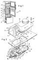
- FIG. 1 shows a multi-temperature household cooling device 10 with a heat insulated Housing 11, within which three cold compartments of different temperatures are provided are, of which the top as a freezer compartment 12, the bottom as a cellar compartment 13 and the one arranged between these two is designed as a normal cooling compartment 14 and each of which rests elastically on the opening edge of the housing 11 Door is lockable.
- the housing 11 has an outer cladding 15, one adjoining heat insulation layer 16 and one by deep drawing a plastic board one piece of inner lining 17 extending over the three cold compartments on, which together with the outer panel 15 a space for insertion the heat insulation layer 16 forms. On the inner panel 17 there is one further down more precisely explained controller-lamp combination.
- the inner lining 17 is for the purpose of Provide bracket with an essentially rectangular opening 18, at its parallel opposite one another, in the direction of its longitudinal axis longer rectangular sides into the free area of the opening 18 projecting projections 19 are arranged.
- the opening 18 is to the heat insulation layer 16 through a bowl-like design, e.g. one-piece made of plastic injection molding manufactured insert 20 covered sealingly, the shell bottom 21 on its free edges is provided with an elastically deformable sealing lip 22, which in the edge region of the opening 18 sealing under a certain preload on the Inner lining 17 is applied.
- the holding lugs 23 are angular in cross section, wherein whose angle leg 24 arranged parallel to the shell bottom 21 has an insertion section 25, an adjoining feed section designed as an inclined plane 26 and an adjoining clamping area 27.
- Retaining lugs 23 are for the form-fitting holding of the insert 20 on the inner lining 17 in and against the locking direction in addition to the narrower Sides to interact with the narrow sides of the breakthrough, in pairs arranged locking lugs 28 and 29 provided, of which the locking lugs 29 with a holding web 30 arranged at a distance above the shell bottom 21 are. Between the locking lugs 28 and 29 is on the tray bottom 21 in the direction depression 31 extending the longitudinal axis of the insert part 20 is provided. This points on its narrow side facing the locking lugs 29 a receiving pocket 32 in which is detachably supported by an electrical plug 33 which can be inserted therein electrical connections serving contact elements 34 protrude into the recess 31 and with electrical lines 35 are contacted.
- the lines 35 are on their circumference of an elastic sealing element 36 which is held in the assembled state of the plug 33 is arranged within the receiving pocket 32 and which with its circumference an elastic sealing lip 37 is provided, which with the wall facing it the receiving pocket 32 is able to cooperate in a foam-tight manner.
- the insert 20 is further equipped with a guide channel 38, which for the section-wise inclusion and guidance of a controller-lamp combination 40 belonging sensor tube 41, which is not shown, near the door Area assigned to the controller-lamp combination 40 provided constant controller is, which for the purpose of temperature control within the normal refrigerator 14 with an adjustment knob 42 is equipped.
- a lighting device 43 which can be replaced by a on the bottom of the lighting device arranged reflector 44 and a reflector, not shown in the present case, is formed by a transparent cover 45 light bulb.
- the lighting device 43 has on the outside of the reflector 44 opposite Bottom a retaining hook 46, the free hook end of the adjusting knob 42nd is directed away.
- a receiving bore 47 is provided for introducing a fastening screw 48.
- a receptacle 49 is provided, in which a plug-like holding element 50 is releasably held, within which for electrical Contacting serving spring contacts are arranged, which on the one hand to the incandescent lamp and on the other hand contacted electrical lines leading to the constant regulator are.
- the Insert 20 attached to the inner panel 17. This is done with the plug 33 and the connected electrical line 35 with pre-assembled insert 20 its holding elements 23 positioned to the opening 18 that the holding elements 23 with their insertion section 25 are upstream of the projections 19.
- the insert 20 is moved in the direction of the arrow (towards the opening of the normal cooling compartment 14), whereby the insertion sections, followed by the feed sections and ultimately the clamping areas of the holding elements 23 with the projections 19 in the manner of a Bayonet lock are engaged.
Landscapes
- Engineering & Computer Science (AREA)
- General Engineering & Computer Science (AREA)
- Chemical & Material Sciences (AREA)
- Combustion & Propulsion (AREA)
- Physics & Mathematics (AREA)
- Mechanical Engineering (AREA)
- Thermal Sciences (AREA)
- Devices That Are Associated With Refrigeration Equipment (AREA)
- Arrangement Of Elements, Cooling, Sealing, Or The Like Of Lighting Devices (AREA)
- Fastening Of Light Sources Or Lamp Holders (AREA)
Abstract
Description
- Fig. 1
- ein Mehrtemperaturen-Haushaltskühlgerät, dessen Normalkühlfach mit einer an seiner Innenverkleidung festgesetzten Regler-Leuchtenkombination versehen ist, in raumbildlicher Ansicht von vorne und
- Fig. 2
- die Regler-Leuchtenkombination im von der Innenverkleidung abgezogenen Zustand, in raumbildlicher Ansicht von der Seite.
Claims (12)
- Kühlgerät (10) mit einem wärmeisolierten Gehäuse (11), gebildet aus einer Außenverkleidung (15), einer Wärmeisolationsschicht (16) und einer den Nutzraum (12, 13, 14) des Kühlraumes umgrenzenden Innenverkleidung (17) an welcher eine Beleuchtungseinrichtung (40) zur Ausleuchtung des Innenraumes vorgesehen ist, dadurch gekennzeichnet, daß die Innenverkleidung (17) einen Durchbruch (18) aufweist, welcher von einem wärmeisolationsseitig angeordneten Einlegeteil (20) abgedeckt ist, welches mit elektrischen Anschlüssen (34) und mit Mitteln zur Befestigung der Beleuchtungseinrichtung (40) versehen ist, welche am Einlegeteil (20) durch eine Schiebebewegung in Richtung zur Längsachse des Einlegeteiles (20) befestigt und mit den elektrischen Anschlüssen (34) kontaktiert ist.
- Kühlgerät nach Anspruch 1, dadurch gekennzeichnet, daß das Einlegeteil (20) an den freien Rändern des Durchbruches (18) durch eine bajonettähnliche ausgebildete Verriegelung gehaltert ist, deren Verriegelungsrichtung in Richtung zur Längsachse des Einlegeteiles (20) verläuft.
- Kühlgerät nach Anspruch 2, dadurch gekennzeichnet, daß die bajonettähnliche Verriegelung des Einlegeteiles (20) an den in Richtung der Längsachse verlaufenden Rändern des Durchbruches (18) vorgesehen ist.
- Kühlgerät nach einem der Ansprüche 2 und 3, dadurch gekennzeichnet, daß das Einlegeteil (20) in seiner Verriegelungsstellung in und entgegen der Verriegelungsrichtung durch Haltemittel formschlüssig gehalten ist.
- Kühlgerät nach einem der Ansprüche 2 bis 4, dadurch gekennzeichnet, daß das Einlegeteil (20) in Richtung zur Öffnung des Nutzraumes (14) hin in seine Verriegelungsstellung bringbar ist.
- Kühlgerät nach einem der Ansprüche 1 bis 5, dadurch gekennzeichnet, daß am Einlegeteil (20) die Mittel zur Befestigung der Beleuchtungseinrichtung (40) bajonettähnlich mit Haltemitteln an der Beleuchtungseinrichtung (40) zusammenzuwirken vermögen.
- Kühlgerät nach einem der Ansprüche 1 bis 5, dadurch gekennzeichnet, daß am Einlegeteil (20) die Mittel zur Befestigung der Beleuchtungseinrichtung (40) als wenigstens ein einzelner Haltebügel (30) ausgebildet sind, mit welchem eine Haltenase (46) an der Beleuchtungseinrichtung (40) form- und/oder kraftschlüssig zur Längsachse des Einlegeteiles (20) zusammenzuwirken vermag.
- Kühlgerät nach einem der Ansprüche 1 bis 7, dadurch gekennzeichnet, daß das Einlegeteil (20) eine zur Wärmeisolation (16) gerichtete, in Richtung der Längsachse des Einlegeteiles (20) angeordnete, längsgestreckte Vertiefung (31) aufweist, an deren einem Ende eine in Richtung der Längsachse beiderseits geöffnete Aufnahmetasche (32) vorgesehen ist, welche einen mit als elektrische Anschlüsse dienenden Kontaktelementen 34 versehenen Stecker (33) in abdichtender Weise entlang seiner Außenkontur zu halten vermag.
- Kühlgerät nach einem der Ansprüche 1 bis 8, dadurch gekennzeichnet, daß das Einlegeteil (20) eine umlaufend angeordnete, dichtend an der Innenverkleidung (17) im Randbereich des Durchbruches (18) anliegende elastische Dichtlippe 22) aufweist.
- Kühlgerät nach Anspruch 1, dadurch gekennzeichnet, daß die Beleuchtungseinrichtung (40) eine Aufnahme (49) aufweist, welche ein mit Federkontakten (51) bestücktes, zumindest teilweise in die Aufnahmetasche (32) einführbares Halteelement (50) form- und/oder kraftschlüssig zu haltern vermag.
- Kühlgerät nach Anspruch 1 oder 10, dadurch gekennzeichnet, daß die Beleuchtungseinrichtung (40) mit einem lösbar gehalterten Reflektor (44) versehen ist.
- Kühlgerät nach einem der Ansprüche 1,10 oder 11, dadurch gekennzeichnet, daß die Beleuchtungseinrichtung (40) am Einlegeteil (20) in dessen Verriegelungsrichtung verriegelbar ist.
Applications Claiming Priority (3)
| Application Number | Priority Date | Filing Date | Title |
|---|---|---|---|
| DE19730357 | 1997-07-15 | ||
| DE19730357A DE19730357A1 (de) | 1997-07-15 | 1997-07-15 | Kühlgerät |
| PCT/EP1998/004353 WO1999004208A1 (de) | 1997-07-15 | 1998-07-13 | Kühlgerät |
Publications (2)
| Publication Number | Publication Date |
|---|---|
| EP0995070A1 EP0995070A1 (de) | 2000-04-26 |
| EP0995070B1 true EP0995070B1 (de) | 2002-05-08 |
Family
ID=7835803
Family Applications (2)
| Application Number | Title | Priority Date | Filing Date |
|---|---|---|---|
| EP98202253A Expired - Lifetime EP0892230B1 (de) | 1997-07-15 | 1998-07-04 | Kühlschrank |
| EP98941326A Expired - Lifetime EP0995070B1 (de) | 1997-07-15 | 1998-07-13 | Kühlgerät |
Family Applications Before (1)
| Application Number | Title | Priority Date | Filing Date |
|---|---|---|---|
| EP98202253A Expired - Lifetime EP0892230B1 (de) | 1997-07-15 | 1998-07-04 | Kühlschrank |
Country Status (9)
| Country | Link |
|---|---|
| EP (2) | EP0892230B1 (de) |
| CN (1) | CN1143116C (de) |
| BR (1) | BR9811504A (de) |
| DE (3) | DE19730357A1 (de) |
| ES (2) | ES2209054T3 (de) |
| PL (1) | PL189707B1 (de) |
| RU (1) | RU2196282C2 (de) |
| TR (1) | TR200000432T2 (de) |
| WO (1) | WO1999004208A1 (de) |
Cited By (1)
| Publication number | Priority date | Publication date | Assignee | Title |
|---|---|---|---|---|
| DE102022201019A1 (de) | 2022-02-01 | 2023-08-03 | BSH Hausgeräte GmbH | Haushaltskältegerät mit spezifisch orientierten Stecker und Gegenstecker in einem Durchbruch einer Wand, sowie Verfahren |
Families Citing this family (31)
| Publication number | Priority date | Publication date | Assignee | Title |
|---|---|---|---|---|
| DE10122878B4 (de) * | 2001-05-11 | 2015-03-26 | BSH Bosch und Siemens Hausgeräte GmbH | Beleuchtungseinrichtung für Backöfen |
| TWI321211B (en) * | 2003-06-30 | 2010-03-01 | Sanyo Electric Co | Interior lamp socket and refrigerator using the same |
| DE102004045475A1 (de) * | 2004-09-20 | 2006-03-30 | BSH Bosch und Siemens Hausgeräte GmbH | Bauteil zur Montage an einer hinterschäumten Wand und damit ausgestattetes Kältegerät |
| DE102005017120A1 (de) * | 2005-04-11 | 2006-10-19 | MENTOR GmbH & Co. Präzisions-Bauteile KG | Kontrolleinheit für einen verschließbaren Behälter |
| DE102006005290A1 (de) * | 2006-02-06 | 2007-08-09 | BSH Bosch und Siemens Hausgeräte GmbH | Beleuchtungsbaugruppe für ein Haushaltsgerät |
| DE102006012921A1 (de) * | 2006-03-21 | 2007-09-27 | BSH Bosch und Siemens Hausgeräte GmbH | Bauteil zur Montage an einer Wand und damit ausgestattetes Gerätegehäuse |
| DE102006012923A1 (de) * | 2006-03-21 | 2007-09-27 | BSH Bosch und Siemens Hausgeräte GmbH | Bauteil zur Montage an einer Wand und damit ausgestattetes Gerätegehäuse |
| DE102006012922A1 (de) | 2006-03-21 | 2007-09-27 | BSH Bosch und Siemens Hausgeräte GmbH | Anordnung mit einer Wand und einem in einer Öffnung der Wand verankerten Bauteil |
| DE202007004077U1 (de) * | 2007-02-08 | 2008-06-19 | Liebherr-Hausgeräte Ochsenhausen GmbH | Kühl- und/oder Gefriergerät |
| WO2008098576A1 (en) * | 2007-02-14 | 2008-08-21 | Danfoss A/S | Illuminating device for a refrigeration appliance |
| AU2014201253B2 (en) * | 2007-04-26 | 2014-09-25 | Maslen Technology Australia Pty Ltd | Light cover/diffuser for food cabinets |
| RU2431791C1 (ru) * | 2007-06-25 | 2011-10-20 | Бсх Бош Унд Сименс Хаусгерете Гмбх | Осветительно-воздуходувное устройство для холодильного аппарата |
| DE102009000667A1 (de) * | 2009-02-06 | 2010-08-12 | BSH Bosch und Siemens Hausgeräte GmbH | Haushaltskühlgerät mit einem Aufnahmeraum |
| DE102010003826A1 (de) * | 2010-04-09 | 2011-10-13 | BSH Bosch und Siemens Hausgeräte GmbH | Kältegerät mit Beleuchtungseinrichtung |
| DE102010043546A1 (de) * | 2010-11-08 | 2012-05-10 | BSH Bosch und Siemens Hausgeräte GmbH | Hinterlegteil für die Befestigung einer elektrischen Komponente an einer Gehäusewand |
| DE102010043545A1 (de) | 2010-11-08 | 2012-05-10 | BSH Bosch und Siemens Hausgeräte GmbH | Beleuchtungseinrichtung für ein Großelektrogerät |
| CN102410700B (zh) * | 2011-09-13 | 2016-06-08 | 海尔集团公司 | 冰箱照明装置及冰箱 |
| DE102011084908A1 (de) | 2011-10-20 | 2013-04-25 | BSH Bosch und Siemens Hausgeräte GmbH | Kältegerät, insbesondere Haushaltskältegerät |
| US10598429B2 (en) | 2012-12-14 | 2020-03-24 | Arcelik Anonim Sirketi | Cooling device comprising of a knob providing the adjustment of the compartment temperature |
| WO2014135388A1 (en) * | 2013-03-08 | 2014-09-12 | BSH Bosch und Siemens Hausgeräte GmbH | Illuminating device for a household appliance and household appliance with such an illuminating device |
| DE102014225245A1 (de) * | 2014-12-09 | 2016-06-09 | BSH Hausgeräte GmbH | Haushaltsgerät mit einer Beleuchtungseinrichtung |
| DE102015216921A1 (de) | 2015-09-03 | 2017-03-09 | BSH Hausgeräte GmbH | Kältegerät, insbesondere Haushaltskältegerät, und Verfahren zu dessen Herstellung |
| DE102015221431A1 (de) | 2015-11-02 | 2017-05-04 | BSH Hausgeräte GmbH | Kältegerät mit Hinterlegteil und Verfahren zum Herstellen eines Kältegerätes mit Hinterlegteil |
| CN105444512B (zh) * | 2015-12-08 | 2017-10-31 | 广东奥马冰箱有限公司 | 一种冰箱用的机械式控制器 |
| DE102019210662A1 (de) | 2019-07-18 | 2021-01-21 | BSH Hausgeräte GmbH | Innenbehälter mit einer eine Tasche aufweisenden Lochaussparung, Haushaltskältegerät sowie Verfahren zur Montage eines Anbauteils an einem Innenbehälter |
| DE102019219105A1 (de) * | 2019-12-06 | 2021-06-10 | BSH Hausgeräte GmbH | Haushaltskältegerät mit einem Hinterlegteil und Verfahren zum Herstellen des Haushaltskältegerätes |
| EP3882545B1 (de) * | 2020-03-18 | 2025-08-20 | BSH Hausgeräte GmbH | Haushaltsgerät mit leuchte für behandlungsraum |
| DE102021200493A1 (de) | 2021-01-20 | 2022-07-21 | BSH Hausgeräte GmbH | Montageverfahren einer Kamera an einer Innenbehälterwand eines Haushaltsgeräts, sowie Haushaltsgerät |
| DE102021105831A1 (de) | 2021-03-10 | 2022-09-15 | Liebherr-Hausgeräte Ochsenhausen GmbH | Kühl- und/oder Gefriergerät |
| KR20230161812A (ko) * | 2022-05-19 | 2023-11-28 | 엘지전자 주식회사 | 냉장고 |
| DE102022208676A1 (de) | 2022-08-22 | 2024-02-22 | BSH Hausgeräte GmbH | Haushaltsgerät-Elektronikgehäuse und Haushaltsgerät damit |
Family Cites Families (8)
| Publication number | Priority date | Publication date | Assignee | Title |
|---|---|---|---|---|
| GB1065221A (en) * | 1963-07-19 | 1967-04-12 | Licentia Gmbh | An assembly of electrical components for temperature control and lighting of a refrigerator cabinet |
| DE3503510A1 (de) * | 1985-02-02 | 1986-08-07 | Bauknecht Hausgeräte GmbH, 7000 Stuttgart | Kuehlschrank |
| DE8602774U1 (de) * | 1986-02-04 | 1986-03-27 | Brökelmann, Jaeger & Busse GmbH & Co, 5760 Arnsberg | Beleuchtungsvorrichtung für Backöfen, Kühlschränke od. dgl. |
| FR2602028B1 (fr) * | 1986-07-30 | 1990-12-28 | Beghelli G P B Srl | Systeme a jonction rapide pour lampes |
| DE3703532A1 (de) * | 1987-02-06 | 1988-08-18 | Licentia Gmbh | Kuehlgeraet mit einer beleuchtungseinrichtung |
| IT214575Z2 (it) * | 1988-06-03 | 1990-05-09 | Itw Fastex Italia Spa | Dispositivo portalampada per elettrodomestici |
| DE4100026A1 (de) * | 1991-01-03 | 1992-07-09 | Hurst & Schroeder Gmbh | Herdleuchte |
| DE9401398U1 (de) * | 1993-10-27 | 1995-02-23 | Liebherr-Hausgeräte GmbH, 88416 Ochsenhausen | Beleuchtung für den Kühlraum eines Kühl- oder Gefrierschrankes |
-
1997
- 1997-07-15 DE DE19730357A patent/DE19730357A1/de not_active Withdrawn
-
1998
- 1998-07-04 EP EP98202253A patent/EP0892230B1/de not_active Expired - Lifetime
- 1998-07-04 DE DE69818568T patent/DE69818568T2/de not_active Expired - Lifetime
- 1998-07-04 ES ES98202253T patent/ES2209054T3/es not_active Expired - Lifetime
- 1998-07-13 EP EP98941326A patent/EP0995070B1/de not_active Expired - Lifetime
- 1998-07-13 ES ES98941326T patent/ES2177041T3/es not_active Expired - Lifetime
- 1998-07-13 WO PCT/EP1998/004353 patent/WO1999004208A1/de not_active Ceased
- 1998-07-13 TR TR2000/00432T patent/TR200000432T2/xx unknown
- 1998-07-13 PL PL98337989A patent/PL189707B1/pl not_active IP Right Cessation
- 1998-07-13 DE DE59804064T patent/DE59804064D1/de not_active Expired - Lifetime
- 1998-07-13 CN CNB988058901A patent/CN1143116C/zh not_active Expired - Fee Related
- 1998-07-13 BR BR9811504-9A patent/BR9811504A/pt not_active IP Right Cessation
- 1998-07-13 RU RU2000103439/13A patent/RU2196282C2/ru not_active IP Right Cessation
Cited By (1)
| Publication number | Priority date | Publication date | Assignee | Title |
|---|---|---|---|---|
| DE102022201019A1 (de) | 2022-02-01 | 2023-08-03 | BSH Hausgeräte GmbH | Haushaltskältegerät mit spezifisch orientierten Stecker und Gegenstecker in einem Durchbruch einer Wand, sowie Verfahren |
Also Published As
| Publication number | Publication date |
|---|---|
| CN1143116C (zh) | 2004-03-24 |
| DE69818568D1 (de) | 2003-11-06 |
| EP0892230B1 (de) | 2003-10-01 |
| DE59804064D1 (de) | 2002-06-13 |
| WO1999004208A1 (de) | 1999-01-28 |
| BR9811504A (pt) | 2000-09-26 |
| EP0892230A1 (de) | 1999-01-20 |
| PL189707B1 (pl) | 2005-09-30 |
| PL337989A1 (en) | 2000-09-25 |
| RU2196282C2 (ru) | 2003-01-10 |
| DE69818568T2 (de) | 2004-04-29 |
| CN1259199A (zh) | 2000-07-05 |
| DE19730357A1 (de) | 1999-01-21 |
| EP0995070A1 (de) | 2000-04-26 |
| ES2177041T3 (es) | 2002-12-01 |
| ES2209054T3 (es) | 2004-06-16 |
| TR200000432T2 (tr) | 2000-05-22 |
Similar Documents
| Publication | Publication Date | Title |
|---|---|---|
| EP0995070A1 (de) | Kühlgerät | |
| EP3074705B1 (de) | Haushaltskältegerät mit einer innenraumbeleuchtung | |
| DE29606772U1 (de) | Vorrichtung zum elektrischen Anschluß von Kühlgerätebauteilen | |
| DE102018205757A1 (de) | Haushaltskältegerät mit einer Innenraumbeleuchtung und Verfahren zum Herstellen des Haushaltskältegerätes | |
| DE102019205875A1 (de) | Haushaltskältegerät und Verfahren zum Herstellen eines Haushaltskältegerätes | |
| EP3784962B1 (de) | Haushaltskältegerät mit einem hinterlegteil und verfahren zum herstellen des haushaltskältegerätes | |
| DE10163056A1 (de) | Lampenfassung | |
| EP3417221B1 (de) | Haushaltskältegerät mit einer innenraumbeleuchtung und verfahren zum herstellen eines haushaltskältegerätes | |
| EP2606303B1 (de) | Kältegerät mit einer innenbeleuchtung | |
| EP0475065B1 (de) | Innenleuchte für Kraftfahrzeuge | |
| DE102011107610B4 (de) | Leitungshalter zur Befestigung an einem Träger einer Flugzeugstruktur | |
| DE19704067A1 (de) | Beleuchtungseinrichtung für Fahrzeuge | |
| DE8525839U1 (de) | Leuchte | |
| EP0440897A1 (de) | Innenleuchte für Fahrzeuge | |
| DE102021212929A1 (de) | Kältegerät, Verdampferbaugruppe für ein Kältegerät, Halter und Verfahren zum Fixieren einer Sensoreinrichtung an einem Rohr eines Verdampfers | |
| DE4405721C1 (de) | Leuchte für den Innenraum von Kraftfahrzeugen | |
| DE19737989B4 (de) | Verbesserungen an Kraftfahrzeugscheinwerfern mit abnehmbarem Elektronikgehäuse | |
| EP0856122A1 (de) | Scheinwerfer für fahrzeuge | |
| DE8530507U1 (de) | Schließvorrichtung für eine Gefrierfachtür | |
| EP0705731B1 (de) | Fahrzeugleuchte, insbesondere Kennzeichenleuchte | |
| DE7603565U1 (de) | Kuehlgeraet, insbesondere kuehlschrank o.dgl. | |
| DE1248074B (de) | An der Kuehlraumwand eines Kuehlschranks zu befestigendes Gehaeuse zur Aufnahme und zum Abdecken elektrischer Einrichtungen | |
| DE29824827U1 (de) | Kühlschrank | |
| DE10024893A1 (de) | Kältegerät, das vorzugsweise nach dem Absorberprinzip arbeitet, sowie Fahrzeug mit einem derartigen Kältegerät | |
| DE2104420C3 (de) | Leuchte für Kraftfahrzeuge, insbesondere Schlußleuchte |
Legal Events
| Date | Code | Title | Description |
|---|---|---|---|
| PUAI | Public reference made under article 153(3) epc to a published international application that has entered the european phase |
Free format text: ORIGINAL CODE: 0009012 |
|
| 17P | Request for examination filed |
Effective date: 20000215 |
|
| AK | Designated contracting states |
Kind code of ref document: A1 Designated state(s): DE ES FR GB IT SE |
|
| GRAG | Despatch of communication of intention to grant |
Free format text: ORIGINAL CODE: EPIDOS AGRA |
|
| 17Q | First examination report despatched |
Effective date: 20010821 |
|
| GRAG | Despatch of communication of intention to grant |
Free format text: ORIGINAL CODE: EPIDOS AGRA |
|
| GRAH | Despatch of communication of intention to grant a patent |
Free format text: ORIGINAL CODE: EPIDOS IGRA |
|
| REG | Reference to a national code |
Ref country code: GB Ref legal event code: IF02 |
|
| GRAH | Despatch of communication of intention to grant a patent |
Free format text: ORIGINAL CODE: EPIDOS IGRA |
|
| GRAA | (expected) grant |
Free format text: ORIGINAL CODE: 0009210 |
|
| AK | Designated contracting states |
Kind code of ref document: B1 Designated state(s): DE ES FR GB IT SE |
|
| GBT | Gb: translation of ep patent filed (gb section 77(6)(a)/1977) |
Effective date: 20020509 |
|
| REF | Corresponds to: |
Ref document number: 59804064 Country of ref document: DE Date of ref document: 20020613 |
|
| ET | Fr: translation filed | ||
| REG | Reference to a national code |
Ref country code: ES Ref legal event code: FG2A Ref document number: 2177041 Country of ref document: ES Kind code of ref document: T3 |
|
| PLBE | No opposition filed within time limit |
Free format text: ORIGINAL CODE: 0009261 |
|
| STAA | Information on the status of an ep patent application or granted ep patent |
Free format text: STATUS: NO OPPOSITION FILED WITHIN TIME LIMIT |
|
| 26N | No opposition filed |
Effective date: 20030211 |
|
| PGFP | Annual fee paid to national office [announced via postgrant information from national office to epo] |
Ref country code: SE Payment date: 20040723 Year of fee payment: 7 |
|
| PG25 | Lapsed in a contracting state [announced via postgrant information from national office to epo] |
Ref country code: SE Free format text: LAPSE BECAUSE OF NON-PAYMENT OF DUE FEES Effective date: 20050714 |
|
| EUG | Se: european patent has lapsed | ||
| PGFP | Annual fee paid to national office [announced via postgrant information from national office to epo] |
Ref country code: DE Payment date: 20130731 Year of fee payment: 16 Ref country code: ES Payment date: 20130722 Year of fee payment: 16 |
|
| PGFP | Annual fee paid to national office [announced via postgrant information from national office to epo] |
Ref country code: GB Payment date: 20130723 Year of fee payment: 16 Ref country code: FR Payment date: 20130719 Year of fee payment: 16 |
|
| PGFP | Annual fee paid to national office [announced via postgrant information from national office to epo] |
Ref country code: IT Payment date: 20130730 Year of fee payment: 16 |
|
| REG | Reference to a national code |
Ref country code: DE Ref legal event code: R119 Ref document number: 59804064 Country of ref document: DE |
|
| GBPC | Gb: european patent ceased through non-payment of renewal fee |
Effective date: 20140713 |
|
| REG | Reference to a national code |
Ref country code: FR Ref legal event code: ST Effective date: 20150331 |
|
| PG25 | Lapsed in a contracting state [announced via postgrant information from national office to epo] |
Ref country code: DE Free format text: LAPSE BECAUSE OF NON-PAYMENT OF DUE FEES Effective date: 20150203 Ref country code: IT Free format text: LAPSE BECAUSE OF NON-PAYMENT OF DUE FEES Effective date: 20140713 |
|
| REG | Reference to a national code |
Ref country code: DE Ref legal event code: R119 Ref document number: 59804064 Country of ref document: DE Effective date: 20150203 |
|
| PG25 | Lapsed in a contracting state [announced via postgrant information from national office to epo] |
Ref country code: FR Free format text: LAPSE BECAUSE OF NON-PAYMENT OF DUE FEES Effective date: 20140731 Ref country code: GB Free format text: LAPSE BECAUSE OF NON-PAYMENT OF DUE FEES Effective date: 20140713 |
|
| REG | Reference to a national code |
Ref country code: ES Ref legal event code: FD2A Effective date: 20150826 |
|
| PG25 | Lapsed in a contracting state [announced via postgrant information from national office to epo] |
Ref country code: ES Free format text: LAPSE BECAUSE OF NON-PAYMENT OF DUE FEES Effective date: 20140714 |