EP0993003A2 - Sicherheitskontaktschiene oder Sicherheitskontaktelement - Google Patents
Sicherheitskontaktschiene oder Sicherheitskontaktelement Download PDFInfo
- Publication number
- EP0993003A2 EP0993003A2 EP99117389A EP99117389A EP0993003A2 EP 0993003 A2 EP0993003 A2 EP 0993003A2 EP 99117389 A EP99117389 A EP 99117389A EP 99117389 A EP99117389 A EP 99117389A EP 0993003 A2 EP0993003 A2 EP 0993003A2
- Authority
- EP
- European Patent Office
- Prior art keywords
- safety contact
- contact element
- projections
- contact rail
- safety
- Prior art date
- Legal status (The legal status is an assumption and is not a legal conclusion. Google has not performed a legal analysis and makes no representation as to the accuracy of the status listed.)
- Granted
Links
Images


Classifications
-
- H—ELECTRICITY
- H01—ELECTRIC ELEMENTS
- H01B—CABLES; CONDUCTORS; INSULATORS; SELECTION OF MATERIALS FOR THEIR CONDUCTIVE, INSULATING OR DIELECTRIC PROPERTIES
- H01B7/00—Insulated conductors or cables characterised by their form
- H01B7/10—Contact cables, i.e. having conductors which may be brought into contact by distortion of the cable
- H01B7/104—Contact cables, i.e. having conductors which may be brought into contact by distortion of the cable responsive to pressure
-
- H—ELECTRICITY
- H01—ELECTRIC ELEMENTS
- H01H—ELECTRIC SWITCHES; RELAYS; SELECTORS; EMERGENCY PROTECTIVE DEVICES
- H01H2203/00—Form of contacts
- H01H2203/036—Form of contacts to solve particular problems
- H01H2203/054—Form of contacts to solve particular problems for redundancy, e.g. several contact pairs in parallel
-
- H—ELECTRICITY
- H01—ELECTRIC ELEMENTS
- H01H—ELECTRIC SWITCHES; RELAYS; SELECTORS; EMERGENCY PROTECTIVE DEVICES
- H01H3/00—Mechanisms for operating contacts
- H01H3/02—Operating parts, i.e. for operating driving mechanism by a mechanical force external to the switch
- H01H3/14—Operating parts, i.e. for operating driving mechanism by a mechanical force external to the switch adapted for operation by a part of the human body other than the hand, e.g. by foot
- H01H3/141—Cushion or mat switches
- H01H3/142—Cushion or mat switches of the elongated strip type
Definitions
- the invention relates to a safety contact rail for power-operated systems and the like or a safety contact element as a switching hose and the like with an elastic Hollow profile, within which several strip-like, electrically conductive Protrusions are provided that are mutually non-conductive Cross sections are insulated, the conductive protrusions being mutual Touch to generate a switching pulse.
- the object of the present invention is the generic safety contact rail or a safety contact element improve that there is always redundant contacting, and regardless of the direction in which the trigger force on the Safety contact rail or the safety contact element acts.
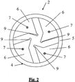
- the object of the invention is achieved in that at least four strip-like, electrically conductive projections are provided and that these projections are uniform and even within of the hollow profile are distributed.
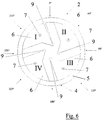
- the cross-sectional areas the projections are preferably chosen and arranged so that they are point symmetrical to the central axis of the hollow profile run. It does not matter from which direction the force is applied on the safety contact rail or the safety contact element is initiated because there are always at least two projections touch each other and generate switching impulses against each other.
- the cross-sectional areas of the projections are shaped so that they are essentially two right-angled triangles with different ones long legs can be defined. They exist of course not from two triangles, but they can be in corresponding ones Triangles divided and described thereby.
- the Large triangles border the inner circumference with their hypotenuses of the hollow profile or form a partial circumference of the hollow profile itself, the hypotenuses are not designed as a straight line, but rather corresponding to the inner circumference of the hollow profile or the outer circumference of the hollow profile are curved.
- the big triangles small triangles join in such a way that they align with the long ones Thighs of the large triangles ajar with their long thighs so that the short legs of the large and small triangles form a straight line.
- strip-like noses attached, essentially in extension of the hypotenuses of the small triangles and the surfaces of the small legs tower over the small triangles.
- This configuration of the Cross-sectional areas of the projections arise in the interior of the hollow profiles a cavity along the safety contact rail or the safety contact element, the one in the center by a square Cross-sectional area is defined, on the side faces of each one Edge then cavity strips are formed by the strip-like Noses are narrowed, being angled at these strips staggeredly connect further cavity strips up to the non-conductive Cross section of the hollow profile are sufficient. It became conscious small contact area, especially via the strip-like noses chosen. This leads to a high contact pressure, which leads to self-cleaning of the contact surfaces.
- Carbon or graphite fibers can be incorporated.
- the safety contact rail or the safety contact element can have two different types of non-conductive areas.
- the sheath from not conductive material is made.
- the cross sections the strip-like projections themselves part of the outer circumference of the hollow profile, with non-conductive sections between them are provided.
- the outer circumference of the hollow profile completely non-conductive because of the non-conductive shell is surrounded, while in other cases conductive and non-conductive areas are provided which cover the outer circumference of the Form hollow profile.
- the profile is also insensitive to external influences such as moisture and the like, because no "external contact" can take place.
- the safety contact rail or the Safety contact element with the elastic hollow profile made of extrudable Material, especially rubber or polymers and in one piece including any embedded wires or strands preferably produced as an endless profile in an extruder, so that a homogeneous profile is created.
- Hollow profiles can also be used 6 or 8 or more protrusions can be made and used.
- connection side is then connected to a four-channel evaluator, ie to a connection line with four poles.
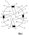
- the safety contact element 2 according to FIG. 3 differs from Fig. 2 essentially in that no sleeve 5 is provided and that instead between the electrically conductive projections 6 electrically non-conductive sections 8 are arranged. Both the safety contact rail as well as the safety contact element extruded in one piece including the copper strands.
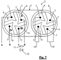
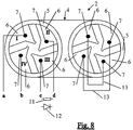
- FIG. 7 to 9 are the two end cross sections of an arbitrarily long safety contact element, with the top and bottom lines connecting the two Profile cross sections represents the safety contact element. Left is reproduced the connection side and on the right is the connection opposite end of the safety contact element shown.
- the copper strands of the conductive protrusions 6 are one above the other are arranged by parallel bracket 10 on the right Side of the figure interconnected.
- On the left are the Connections that are connected to the copper strands there with a to d designated. They are all used when a four-way connection is chosen with the appropriate technology. Becomes a bipartite Connection selected, then the connections c and d via a Resistor 11 or a diode 12 bridges.
- Fig. 8 differs from Fig. 7 only in that on the the end of the safety contact element facing away from the connection the copper strands 7 of the projections 6 diagonally over corresponding diagonal bridges 13 are interconnected. On the connection side can choose either two or four wire technology become.
- Fig. 9 shows the same sketched safety contact element as that in Figs. 7 and 8, but with changed connections.
- the four copper strands 7 are connected to one another via four diodes 12 or resistors 11 on the end opposite the connection, that is to say the right side of the figure.
- On the left side all connections a to d are connected to a four-channel evaluator. Table "contact / angular force effect" in the circuit diagram according to Fig.
Landscapes
- Push-Button Switches (AREA)
- Elimination Of Static Electricity (AREA)
- Gloves (AREA)
- Switches Operated By Changes In Physical Conditions (AREA)
Abstract
Description
Die leitenden Querschnitte können aber auch an dem dem Anschluß abgewandten Ende der Sicherheitskontaktschiene oder des Sicherheitskontaktelements mit vier Widerständen oder Dioden flexibel miteinander verbunden sein. Die Anschlußseite ist dann an einen vierkanaligen Auswerter angeschlossen, d. h. an einer Anschlußleitung mit vier Polen.
- Fig. 1:
- einen Querschnitt durch eine Sicherheitskontaktschiene,
- Fig. 2:
- einen Querschnitt durch ein Sicherheitskontaktelement,
- Fig. 3:
- einen Querschnitt durch ein modifiziertes Sicherheitskontaktelement,
- Fig. 4 + 5:
- Querschnitte, in denen Verformungen und Berührungen der leistenartigen Vorsprünge untereinander skizziert sind,
- Fig. 6:
- einen Querschnitt durch ein Sicherheitskontaktelement entsprechend Fig. 2, bei dem zusätzlich Pfeile mit Gradeinteilungen angebracht sind, um die Kontaktgabemöglichkeiten gegenüber der Richtung der äußeren Kraft verdeutlichen zu können,
- Fig. 7:
- ein Schaltschema einer Sicherheitskontaktschiene oder eines Sicherheitskontaktelements, bei dem auf dem dem Anschluß gegenüberliegenden Ende je zwei nebeneinanderliegende elektrisch leitende Vorsprünge durch einen Kontaktbrücke miteinander verbunden sind,
- Fig. 8:
- ein Schaltschema entsprechend Fig. 7, bei dem die leitenden Vorsprünge an dem dem Anschluß abgewandten Ende diagonal mittels einer Kontaktbrücke elektrisch miteinander verbunden sind und
- Fig. 9:
- ein Schaltschema entsprechend den Fig. 7 und 8, bei dem die elektrisch leitenden Vorsprünge an dem dem Anschluß abgewandten Ende mittels vier Widerständen oder vier Dioden flexibel miteinander verbunden sind.
| Tabelle "Kontaktgabe/Winkelkrafteinwirkung" bei dem Schaltschema nach Fig. 7: | |||||
| A und B = Kontaktgabe Sektoren 1, 2 und 3, 4 verbunden | |||||
| Winkel | Sektor | ||||
| 1 | 2 | 3 | 4 | ||
| 0 | A | B | B | A | |
| 45 | A | A, B | B | ||
| 90 | Keine | A | A | B | B |
| 135 | A | A, B | B | ||
| 180 | A | B | B | A | |
| 225 | A | B | A, B | ||
| 270 | Keine | A | A | B | B |
| 315 | A, B | A | B | ||
| 360 | A | B | B | A |
| Tabelle "Kontaktgabe/Winkelkrafteinwirkung" bei dem Schaltschema nach Fig. 9: | ||||
| A und B = Kontaktgabe | ||||
| Winkel | Sektor | |||
| 1 | 2 | 3 | 4 | |
| 0 | A | B | B | A |
| 45 | A | A, B | B | |
| 90 | A | A | B | B |
| 135 | A | A, B | B | |
| 180 | A | B | B | A |
| 225 | A | B | A, B | |
| 270 | A | A | B | B |
| 315 | A, B | A | B | |
| 360 | A | B | B | A |
Claims (11)
- Sicherheitskontaktschiene (1) für kraftbetätigte Anlagen und dergleichen oder Sicherheitskontaktelement (2) als Schaltschlauch und dergleichen mit einem elastischen Hohlprofil (4), innerhalb dessen mehrere leistenartige, elektrisch leitende Vorsprünge (6) vorgesehen sind, die gegeneinander durch nicht leitende Querschnitte isoliert sind, wobei die leitenden Vorsprünge (6) bei gegenseitiger Berührung einen Schaltimpuls erzeugen,
dadurch gekennzeichnet, daß zumindest vier leistenartige elektrisch leitende Vorsprünge (6) vorgesehen sind und daß diese Vorsprünge (6) gleichförmig ausgebildet und gleichmäßig innerhalb des Hohlprofils (4) verteilt angeordnet sind. - Sicherheitskontaktschiene oder Sicherheitskontaktelement nach Anspruch 1,
dadurch gekennzeichnet, daß die Querschnittsflächen der Vorsprünge (6) so gewählt und so angeordnet sind, daß sie punktsymmetrisch zur Mittelachse des Hohlprofils (4) verlaufen. - Sicherheitskontaktschiene oder Sicherheitskontaktelement nach den Ansprüchen 1 oder 2,
dadurch gekennzeichnet, daß die Querschnittsflächen der Vorsprünge (6) im wesentlichen durch zwei rechtwinklige Dreiecke mit unterschiedlich langen Schenkeln definierbar sind, wobei große Dreiecke mit ihren Hypotenusen mit dem Innenumfang des Hohlprofils (4) in Verbindung stehen oder den Außenumfang des Hohlprofils (4) bilden und die Hypotenusen entsprechend gekrümmt sind und wobei kleine Dreiecke sich an die langen Schenkel der großen Dreiecke so anlehnen, daß die kurzen Schenkel der großen und der kleinen Dreiecke eine Gerade bilden. - Sicherheitskontaktschiene oder Sicherheitskontaktelement nach Anspruch 3,
dadurch gekennzeichnet, daß an den Ecken zwischen den Hypotenusen und den kurzen Schenkeln der kleinen Dreiecke leistenartige Nasen (9) vorgesehen sind, die im wesentlichen in Verlängerung der Hypotenusen der kleinen Dreiecke verlaufen und die Flächen der kleinen Schenkel überragen. - Sicherheitskontaktschiene oder Sicherheitskontaktelement nach einem der vorherigen Ansprüche,
dadurch gekennzeichnet, daß innerhalb der leistenartigen Vorsprünge (6) zumindest ein elektrisch leitender Draht oder Litze (7) aus Metall, Kohle- bzw. Graphitphasern eingelagert ist. - Sicherheitskontaktschiene oder Sicherheitskontaktelement nach einem der vorherigen Ansprüche,
dadurch gekennzeichnet, daß die leistenartigen Vorsprünge (6) innerhalb von Hüllen (5) mit ringförmigem Querschnitt angeordnet sind, wobei die Hüllen (5) aus nicht gleitendem Material hergestellt sind. - Sicherheitskontaktschiene oder Sicherheitskontaktelement nach einem der vorherigen Ansprüche,
dadurch gekennzeichnet, daß die gekrümmten Hypotenusen der großen Dreiecke Außenumfangsbereiche des Hohlprofils (4) bilden und daß zwischen den leistenartigen Vorsprünge (6) nicht leitende Abschnitte vorgesehen sind. - Sicherheitskontaktschiene oder Sicherheitskontaktelement nach einem der vorherigen Ansprüche,
dadurch gekennzeichnet, daß die Sicherheitskontaktschiene (1) und das Sicherheitskontaktelement (2) mit dem elastischen Hohlprofil (4) aus extrudierbarem Material, insbesondere Gummi oder Polymeren, hergestellt und einstückig einschließlich ggf. eingebetteter Drähte oder Litzen (7), vorzugsweise als endloses Profil, extrudiert sind. - Sicherheitskontaktschiene oder Sicherheitskontaktelement nach einem der vorherigen Ansprüche,
dadurch gekennzeichnet, daß bei einseitigem elektrischen Anschluß der Sicherheitskontaktschiene (1) oder des Sicherheitskontaktelements (2) an dem dem Anschluß entgegengesetzten Ende bei vier leistenartigen Vorsprünge (6) diese diagonal mit zwei flexiblen Kontaktbrücken (13) elektrisch miteinander verbunden sind und an der Anschlußstelle wahlweise zwei nebeneinander gelagerte Vorsprünge (6) elektrisch angeschlossen sind und die beiden übrigen an der Anschlußseite mittels eines Widerstandes (11) oder einer Diode (12) überbrückt sind oder an der Anschlußstelle ein Auswerter in Vierdrahttechnik angeschlossen ist. - Sicherheitskontaktschiene oder Sicherheitskontaktelement nach einem der vorherigen Ansprüche,
dadurch gekennzeichnet, daß bei einseitigem elektrischen Anschluß der Sicherheitskontaktschiene (1) oder des Sicherheitskontaktelements (2) an dem dem Anschluß entgegengesetzten Ende bei vier leistenartigen Vorsprünge (6) diese parallel mit zwei flexiblen Kontaktbrücken (10) elektrisch miteinander verbunden sind und an der Anschlußstelle wahlweise zwei nebeneinander gelagerte Vorsprünge (6) elektrisch angeschlossen sind und die beiden übrigen an der Anschlußseite mittels eines Widerstandes (11) oder einer Diode (12) überbrückt sind oder an der Anschlußstelle ein Auswerter in Vierdrahttechnik angeschlossen ist. - Sicherheitskontaktschiene oder Sicherheitskontaktelement nach einem der vorherigen Ansprüche,
dadurch gekennzeichnet, daß bei einseitigem elektrischen Anschluß der Sicherheitskontaktschiene (1) oder des Sicherheitskontaktelements (2) an dem dem Anschluß entgegengesetzten Ende die elektrisch leitenden Vorsprünge (6) mit vier Widerständen (11) oder Dioden (12) flexibel miteinander verbunden sind und daß an der Anschlußseite ein vierkanaliger Auswerter angeschlossen ist.
Applications Claiming Priority (3)
| Application Number | Priority Date | Filing Date | Title |
|---|---|---|---|
| DE19846081 | 1998-10-07 | ||
| DE19846081A DE19846081A1 (de) | 1998-10-07 | 1998-10-07 | Sicherheitskontaktschiene oder Sicherheitskontaktelement |
| US09/549,139 US6429375B1 (en) | 1998-10-07 | 2000-04-11 | Safety contact rail or safety contact element |
Publications (3)
| Publication Number | Publication Date |
|---|---|
| EP0993003A2 true EP0993003A2 (de) | 2000-04-12 |
| EP0993003A3 EP0993003A3 (de) | 2001-01-10 |
| EP0993003B1 EP0993003B1 (de) | 2007-02-28 |
Family
ID=26049341
Family Applications (1)
| Application Number | Title | Priority Date | Filing Date |
|---|---|---|---|
| EP99117389A Expired - Lifetime EP0993003B1 (de) | 1998-10-07 | 1999-09-04 | Sicherheitskontaktschiene oder Sicherheitskontaktelement |
Country Status (5)
| Country | Link |
|---|---|
| US (1) | US6429375B1 (de) |
| EP (1) | EP0993003B1 (de) |
| AT (1) | ATE355595T1 (de) |
| DE (2) | DE19846081A1 (de) |
| ES (1) | ES2281947T3 (de) |
Cited By (2)
| Publication number | Priority date | Publication date | Assignee | Title |
|---|---|---|---|---|
| EP2532820A3 (de) * | 2011-06-06 | 2015-04-22 | Mayser GmbH & Co. KG | Hohlprofil für eine elektrische Schaltleiste und Verfahren zum Erfassen von Hindernissen mit einer elektrischen Schaltleiste |
| CN107437442A (zh) * | 2017-07-27 | 2017-12-05 | 安徽新沪电缆有限公司 | 一种电气装备用智能控制电缆 |
Families Citing this family (4)
| Publication number | Priority date | Publication date | Assignee | Title |
|---|---|---|---|---|
| DE102005016929A1 (de) * | 2005-04-13 | 2006-10-19 | Menz, Jürgen | Sicherheitsschaltprofil |
| DE102012003382A1 (de) | 2012-02-22 | 2013-08-22 | Jürgen Menz | Sicherheitsschalteinrichtung |
| JP7037721B2 (ja) * | 2017-12-08 | 2022-03-17 | 日立金属株式会社 | 感圧センサおよび感圧センサの製造方法 |
| JP6341346B1 (ja) * | 2018-02-15 | 2018-06-13 | 日立金属株式会社 | 挟み込み検知スイッチ |
Family Cites Families (8)
| Publication number | Priority date | Publication date | Assignee | Title |
|---|---|---|---|---|
| DE3888966D1 (de) * | 1988-08-05 | 1994-05-11 | Karlheinz Beckhausen | Sicherheitskontaktschiene. |
| DE3921533A1 (de) * | 1989-06-30 | 1991-01-03 | Karlheinz Beckhausen | Sicherheitskontaktschiene |
| DE19509682C1 (de) * | 1994-09-05 | 1996-02-29 | Dancho Zochev Dipl Ing Donkov | Auflaufsicherung |
| DE19502033C1 (de) * | 1995-01-25 | 1996-06-13 | Daimler Benz Ag | Schutzeinrichtung für ein mittels eines Antriebs betätigbares Schließteil eines Kraftfahrzeugs |
| DE19602744C2 (de) * | 1996-01-19 | 1999-04-29 | Mayser Gmbh & Co | Sicherheitsschaltleistenanordnung |
| DE19701412A1 (de) * | 1997-01-17 | 1998-07-23 | Dewitron Elektronik Gmbh | Bandförmige und flexible Schaltungsanordnungen |
| DE19711600A1 (de) * | 1997-03-20 | 1998-09-24 | Karlheinz Beckhausen | Sicherheitskontaktelement |
| EP0935268A3 (de) * | 1998-02-09 | 2000-09-06 | Shinmei Rubber Ind. Co., Ltd. | Omnidirektioneller Kabelschalter |
-
1998
- 1998-10-07 DE DE19846081A patent/DE19846081A1/de not_active Ceased
-
1999
- 1999-09-04 ES ES99117389T patent/ES2281947T3/es not_active Expired - Lifetime
- 1999-09-04 DE DE59914217T patent/DE59914217D1/de not_active Expired - Lifetime
- 1999-09-04 AT AT99117389T patent/ATE355595T1/de active
- 1999-09-04 EP EP99117389A patent/EP0993003B1/de not_active Expired - Lifetime
-
2000
- 2000-04-11 US US09/549,139 patent/US6429375B1/en not_active Expired - Lifetime
Cited By (2)
| Publication number | Priority date | Publication date | Assignee | Title |
|---|---|---|---|---|
| EP2532820A3 (de) * | 2011-06-06 | 2015-04-22 | Mayser GmbH & Co. KG | Hohlprofil für eine elektrische Schaltleiste und Verfahren zum Erfassen von Hindernissen mit einer elektrischen Schaltleiste |
| CN107437442A (zh) * | 2017-07-27 | 2017-12-05 | 安徽新沪电缆有限公司 | 一种电气装备用智能控制电缆 |
Also Published As
| Publication number | Publication date |
|---|---|
| EP0993003A3 (de) | 2001-01-10 |
| DE59914217D1 (de) | 2007-04-12 |
| ES2281947T3 (es) | 2007-10-01 |
| EP0993003B1 (de) | 2007-02-28 |
| ATE355595T1 (de) | 2006-03-15 |
| US6429375B1 (en) | 2002-08-06 |
| DE19846081A1 (de) | 2000-04-13 |
Similar Documents
| Publication | Publication Date | Title |
|---|---|---|
| DE3103305C2 (de) | Elektrisch schweißbare Muffe zum Verbinden von Leitungselementen | |
| DE4340425A1 (de) | Hochimpedanz-Leitungskabel mit abstreifbarer Isolierung | |
| DE3202854C2 (de) | Elektrisch leitfähige Schlauchleitung | |
| EP0978678B1 (de) | Elektrisch leitende Rohr- oder Kabelschelle | |
| EP0993003A2 (de) | Sicherheitskontaktschiene oder Sicherheitskontaktelement | |
| EP1451497B1 (de) | Kunststoffschlauch, insbesondere pneumatikschlauch | |
| DE3408251C2 (de) | ||
| DE966628C (de) | Elektrisches Schaltelement zylinderaehnlicher Gestalt mit stirnseitigen Stromzufuehrungen | |
| WO1999019888A1 (de) | Elektrischer leiter mit dehnungsabhängigem widerstand | |
| DE102007007371A1 (de) | Kontaktkopf eines elektrisch leitfähigen Kabels und Verfahren zum Herstellen eines solchen Kontaktkopfes | |
| DE2925853C2 (de) | Verfahren zum festen Anspritzen eines Kupplungsteils an eine elektrische Leitung | |
| DE19711600A1 (de) | Sicherheitskontaktelement | |
| DE2714275C2 (de) | ||
| DE3439943A1 (de) | Klemme zur halterung von leiterplatten im galvenikbad | |
| DE2255785A1 (de) | Einrichtung zum anschluss eines koaxialkabels | |
| DE10323533A1 (de) | Klemme für chirurgische Anwendungen | |
| DE2660735C2 (de) | Distanzhalter für durch Schutzrohre hindurchgeführte Rohre | |
| EP1217162B1 (de) | Dichtungsvorrichtung | |
| DE3743270C2 (de) | Garnitur zum Anschluß eines Starkstromkabels an ein elektrisches Gerät | |
| DE9308344U1 (de) | Sicherheits-Kontaktschiene | |
| DE7635629U1 (de) | Distanzhalter für durch Schutzrohre hindurchgeführte Rohre | |
| DE1790020C (de) | Vorrichtung zur Verbindung von zwei steifen elektrischen Leitern | |
| DE19638766A1 (de) | Handlauf | |
| DE1807951A1 (de) | Kabelanschlussklemme | |
| DE3545633C2 (de) |
Legal Events
| Date | Code | Title | Description |
|---|---|---|---|
| PUAI | Public reference made under article 153(3) epc to a published international application that has entered the european phase |
Free format text: ORIGINAL CODE: 0009012 |
|
| AK | Designated contracting states |
Kind code of ref document: A2 Designated state(s): AT BE CH CY DE DK ES FI FR GB GR IE IT LI LU MC NL PT SE |
|
| AX | Request for extension of the european patent |
Free format text: AL;LT;LV;MK;RO;SI |
|
| PUAL | Search report despatched |
Free format text: ORIGINAL CODE: 0009013 |
|
| AK | Designated contracting states |
Kind code of ref document: A3 Designated state(s): AT BE CH CY DE DK ES FI FR GB GR IE IT LI LU MC NL PT SE |
|
| AX | Request for extension of the european patent |
Free format text: AL;LT;LV;MK;RO;SI |
|
| 17P | Request for examination filed |
Effective date: 20010530 |
|
| AKX | Designation fees paid |
Free format text: AT BE CH CY DE DK ES FI FR GB GR IE IT LI LU MC NL PT SE |
|
| 17Q | First examination report despatched |
Effective date: 20040924 |
|
| GRAP | Despatch of communication of intention to grant a patent |
Free format text: ORIGINAL CODE: EPIDOSNIGR1 |
|
| GRAS | Grant fee paid |
Free format text: ORIGINAL CODE: EPIDOSNIGR3 |
|
| GRAA | (expected) grant |
Free format text: ORIGINAL CODE: 0009210 |
|
| AK | Designated contracting states |
Kind code of ref document: B1 Designated state(s): AT BE CH CY DE DK ES FI FR GB GR IE IT LI LU MC NL PT SE |
|
| PG25 | Lapsed in a contracting state [announced via postgrant information from national office to epo] |
Ref country code: NL Free format text: LAPSE BECAUSE OF FAILURE TO SUBMIT A TRANSLATION OF THE DESCRIPTION OR TO PAY THE FEE WITHIN THE PRESCRIBED TIME-LIMIT Effective date: 20070228 Ref country code: IE Free format text: LAPSE BECAUSE OF FAILURE TO SUBMIT A TRANSLATION OF THE DESCRIPTION OR TO PAY THE FEE WITHIN THE PRESCRIBED TIME-LIMIT Effective date: 20070228 Ref country code: FI Free format text: LAPSE BECAUSE OF FAILURE TO SUBMIT A TRANSLATION OF THE DESCRIPTION OR TO PAY THE FEE WITHIN THE PRESCRIBED TIME-LIMIT Effective date: 20070228 Ref country code: DK Free format text: LAPSE BECAUSE OF FAILURE TO SUBMIT A TRANSLATION OF THE DESCRIPTION OR TO PAY THE FEE WITHIN THE PRESCRIBED TIME-LIMIT Effective date: 20070228 |
|
| REG | Reference to a national code |
Ref country code: GB Ref legal event code: FG4D Free format text: NOT ENGLISH |
|
| REG | Reference to a national code |
Ref country code: CH Ref legal event code: EP |
|
| REF | Corresponds to: |
Ref document number: 59914217 Country of ref document: DE Date of ref document: 20070412 Kind code of ref document: P |
|
| REG | Reference to a national code |
Ref country code: IE Ref legal event code: FG4D Free format text: LANGUAGE OF EP DOCUMENT: GERMAN |
|
| REG | Reference to a national code |
Ref country code: CH Ref legal event code: NV Representative=s name: R. A. EGLI & CO. PATENTANWAELTE |
|
| REG | Reference to a national code |
Ref country code: SE Ref legal event code: TRGR |
|
| GBT | Gb: translation of ep patent filed (gb section 77(6)(a)/1977) |
Effective date: 20070531 |
|
| PG25 | Lapsed in a contracting state [announced via postgrant information from national office to epo] |
Ref country code: PT Free format text: LAPSE BECAUSE OF FAILURE TO SUBMIT A TRANSLATION OF THE DESCRIPTION OR TO PAY THE FEE WITHIN THE PRESCRIBED TIME-LIMIT Effective date: 20070730 |
|
| NLV1 | Nl: lapsed or annulled due to failure to fulfill the requirements of art. 29p and 29m of the patents act | ||
| ET | Fr: translation filed | ||
| REG | Reference to a national code |
Ref country code: ES Ref legal event code: FG2A Ref document number: 2281947 Country of ref document: ES Kind code of ref document: T3 |
|
| REG | Reference to a national code |
Ref country code: IE Ref legal event code: FD4D |
|
| PLBE | No opposition filed within time limit |
Free format text: ORIGINAL CODE: 0009261 |
|
| STAA | Information on the status of an ep patent application or granted ep patent |
Free format text: STATUS: NO OPPOSITION FILED WITHIN TIME LIMIT |
|
| 26N | No opposition filed |
Effective date: 20071129 |
|
| BERE | Be: lapsed |
Owner name: BECKHAUSEN, KARLHEINZ Effective date: 20070930 |
|
| PG25 | Lapsed in a contracting state [announced via postgrant information from national office to epo] |
Ref country code: MC Free format text: LAPSE BECAUSE OF NON-PAYMENT OF DUE FEES Effective date: 20070930 Ref country code: GR Free format text: LAPSE BECAUSE OF FAILURE TO SUBMIT A TRANSLATION OF THE DESCRIPTION OR TO PAY THE FEE WITHIN THE PRESCRIBED TIME-LIMIT Effective date: 20070529 |
|
| PG25 | Lapsed in a contracting state [announced via postgrant information from national office to epo] |
Ref country code: BE Free format text: LAPSE BECAUSE OF NON-PAYMENT OF DUE FEES Effective date: 20070930 |
|
| PG25 | Lapsed in a contracting state [announced via postgrant information from national office to epo] |
Ref country code: CY Free format text: LAPSE BECAUSE OF FAILURE TO SUBMIT A TRANSLATION OF THE DESCRIPTION OR TO PAY THE FEE WITHIN THE PRESCRIBED TIME-LIMIT Effective date: 20070228 |
|
| PG25 | Lapsed in a contracting state [announced via postgrant information from national office to epo] |
Ref country code: LU Free format text: LAPSE BECAUSE OF NON-PAYMENT OF DUE FEES Effective date: 20070904 |
|
| REG | Reference to a national code |
Ref country code: GB Ref legal event code: 732E Free format text: REGISTERED BETWEEN 20100826 AND 20100901 |
|
| REG | Reference to a national code |
Ref country code: CH Ref legal event code: PUE Owner name: GELBAU GMBH & CO. KG Free format text: BECKHAUSEN, KARLHEINZ#LANDGRAFENSTRASSE 109#50931 KOELN (DE) -TRANSFER TO- GELBAU GMBH & CO. KG#GRANDKAULE 8-10#53859 NIEDERKASSEL (DE) |
|
| REG | Reference to a national code |
Ref country code: FR Ref legal event code: TP |
|
| REG | Reference to a national code |
Ref country code: FR Ref legal event code: PLFP Year of fee payment: 18 |
|
| REG | Reference to a national code |
Ref country code: FR Ref legal event code: PLFP Year of fee payment: 19 |
|
| REG | Reference to a national code |
Ref country code: DE Ref legal event code: R082 Ref document number: 59914217 Country of ref document: DE Representative=s name: GOSDIN, CARSTENSEN & PARTNER PATENTANWAELTE PA, DE Ref country code: DE Ref legal event code: R082 Ref document number: 59914217 Country of ref document: DE Representative=s name: CARSTENSEN & CARSTENSEN PATENTANWAELTE PARTG M, DE |
|
| REG | Reference to a national code |
Ref country code: FR Ref legal event code: PLFP Year of fee payment: 20 |
|
| PGFP | Annual fee paid to national office [announced via postgrant information from national office to epo] |
Ref country code: DE Payment date: 20180927 Year of fee payment: 20 Ref country code: FR Payment date: 20180925 Year of fee payment: 20 |
|
| PGFP | Annual fee paid to national office [announced via postgrant information from national office to epo] |
Ref country code: AT Payment date: 20180830 Year of fee payment: 20 Ref country code: SE Payment date: 20180917 Year of fee payment: 20 |
|
| REG | Reference to a national code |
Ref country code: DE Ref legal event code: R082 Ref document number: 59914217 Country of ref document: DE Representative=s name: GOSDIN, CARSTENSEN & PARTNER PATENTANWAELTE PA, DE |
|
| PGFP | Annual fee paid to national office [announced via postgrant information from national office to epo] |
Ref country code: IT Payment date: 20180927 Year of fee payment: 20 Ref country code: ES Payment date: 20181001 Year of fee payment: 20 Ref country code: GB Payment date: 20181001 Year of fee payment: 20 Ref country code: CH Payment date: 20181224 Year of fee payment: 20 |
|
| REG | Reference to a national code |
Ref country code: DE Ref legal event code: R071 Ref document number: 59914217 Country of ref document: DE |
|
| REG | Reference to a national code |
Ref country code: CH Ref legal event code: PL |
|
| REG | Reference to a national code |
Ref country code: GB Ref legal event code: PE20 Expiry date: 20190903 |
|
| REG | Reference to a national code |
Ref country code: AT Ref legal event code: MK07 Ref document number: 355595 Country of ref document: AT Kind code of ref document: T Effective date: 20190904 |
|
| REG | Reference to a national code |
Ref country code: SE Ref legal event code: EUG |
|
| PG25 | Lapsed in a contracting state [announced via postgrant information from national office to epo] |
Ref country code: GB Free format text: LAPSE BECAUSE OF EXPIRATION OF PROTECTION Effective date: 20190903 |
|
| REG | Reference to a national code |
Ref country code: ES Ref legal event code: FD2A Effective date: 20220127 |
|
| PG25 | Lapsed in a contracting state [announced via postgrant information from national office to epo] |
Ref country code: ES Free format text: LAPSE BECAUSE OF EXPIRATION OF PROTECTION Effective date: 20190905 |