EP0989232A2 - Section de séchage - Google Patents
Section de séchage Download PDFInfo
- Publication number
- EP0989232A2 EP0989232A2 EP99112926A EP99112926A EP0989232A2 EP 0989232 A2 EP0989232 A2 EP 0989232A2 EP 99112926 A EP99112926 A EP 99112926A EP 99112926 A EP99112926 A EP 99112926A EP 0989232 A2 EP0989232 A2 EP 0989232A2
- Authority
- EP
- European Patent Office
- Prior art keywords
- dryer
- section according
- dryer section
- material web
- impingement
- Prior art date
- Legal status (The legal status is an assumption and is not a legal conclusion. Google has not performed a legal analysis and makes no representation as to the accuracy of the status listed.)
- Granted
Links
Images


Classifications
-
- D—TEXTILES; PAPER
- D21—PAPER-MAKING; PRODUCTION OF CELLULOSE
- D21F—PAPER-MAKING MACHINES; METHODS OF PRODUCING PAPER THEREON
- D21F5/00—Dryer section of machines for making continuous webs of paper
- D21F5/18—Drying webs by hot air
- D21F5/182—Drying webs by hot air through perforated cylinders
-
- D—TEXTILES; PAPER
- D21—PAPER-MAKING; PRODUCTION OF CELLULOSE
- D21F—PAPER-MAKING MACHINES; METHODS OF PRODUCING PAPER THEREON
- D21F5/00—Dryer section of machines for making continuous webs of paper
-
- D—TEXTILES; PAPER
- D21—PAPER-MAKING; PRODUCTION OF CELLULOSE
- D21F—PAPER-MAKING MACHINES; METHODS OF PRODUCING PAPER THEREON
- D21F5/00—Dryer section of machines for making continuous webs of paper
- D21F5/18—Drying webs by hot air
Definitions
- the invention relates to a dryer section of a machine for production a material web, in particular a paper or cardboard web.
- the aim of the invention is to provide a dryer section of the type mentioned to create, with at the same time as optimal as possible Drying rate and thus the smallest possible total length of the Drying section possible as well as a safe web guide is guaranteed.
- This object is achieved according to the invention in that it at least comprises a baffle dryer through which the web of material at least on one side with a hot air and / or hot steam impingement flow is acted upon.
- the drying section is the material web with its one through each Impingement flow side opposite side via a open, i.e. not smooth support surface led. This means that the still relatively moist material web of the support surface remains stuck, so that the risk of web breaks and overstretching of the web edges is practically excluded.
- At least one impingement flow dryer with one is expedient steam evacuation for simultaneous evaporation.
- the material web can advantageously together with an intermediate you and the relevant impact flow dryer deck sieve be guided over the support surface.
- the web of material is thus removed from the deck screen supported. Through this deck screen, the material web is on the support surface held and transported in the event of a possible demolition, so that no rejects get caught in the respective impingement dryer can.
- the dryer section is characterized in that the material web has a guided larger backup roller in particular and the open support surface either through the surface or a cover or covering of the support roller or through the surface of an endless belt guided over the support roller is formed.
- the relatively large back-up roller ensures safe and precise guidance with constant radius of curvature. After the backup roller is not more than pressure vessel must be made, it can be relatively large, to provide a correspondingly larger drying area.
- the backup roller can have an outer diameter in the range, for example from about 2 to about 10 m.
- this endless belt can in particular be formed by an air-permeable sieve. Basically this is however, for example, the use of an airtight Conveyor belt conceivable.
- the open support surface can, for example formed by a shrink screen applied to the support roller his.
- Drying section is the open support surface through the surface of a formed over several support rollers support band.
- the open support surface can be guided at least in sections, e.g. over a variety of support rollers.
- sections e.g. over a variety of support rollers.
- the support rollers are on one Arranged circular arc.
- the support band can in particular also be polygonal.
- the material web at least in the removal area through the Compressed air must be applied through the support surface.
- a support roller this can for example provided with a grid structure or perforated and on the inside at least partially pressurized with compressed air or the like his.
- a backup roller can then at least in the removal area, in which the material web and possibly also a deck screen from the backup roller is removed, be pressurized on the inside.
- the temperature of the compressed air is expediently higher than about 20 ° C.
- Impingement flow dryer provided that a hot air or hot steam impingement flow with a temperature in the range of about 150 ° to about 450 ° C generated.
- At least one impingement flow dryer with a plurality used by high performance nozzles these high performance nozzles expediently an equal constant distance during operation own from the material web.
- This distance can be, for example are in the range of about 10 to about 50 mm.
- At least one impingement flow dryer with at least one provided a dryer hood, such a dryer hood advantageously in the direction of web travel and / or transverse to the web direction in Zones can be divided.
- a dryer hood advantageously in the direction of web travel and / or transverse to the web direction in Zones can be divided.
- At least one impingement flow dryer can be in an initial area, for example the dryer section can be provided. Additionally or alternatively can at least one such impingement flow dryer also in a main evaporation zone the dryer section can be provided. Additionally or alternatively can also be at least one in an end region of the dryer section Impingement dryer can be provided. This results in one more higher drying rate, which further shortens the drying section overall becomes.
- a deck screen through both a backup roll impingement dryer as well as an adjoining one straight or slightly curved impingement dryer unit respectively.
- the straight impingement dryer unit can, for example a second sieve can be fed as a support sieve.
- the Paper web for example, can also be transferred to two new screens.
- the Material web for example, also on both sides of a respective hot air or Hot steam impingement flow must be applied.
- one straight or slightly curved path guidance can for example a corresponding impingement flow dryer is also provided on only one side be while on the opposite side for example a plurality of support rollers can be arranged.
- the material web is subjected to a hot air or hot steam impingement flow from one side, on which a large number is arranged by support rollers.
- the application is made especially through the area between the support rollers through it.
- the material web can be at different points from the same side or from different sides with one respective hot air or hot steam impingement flow are applied.
- FIGS. 1 to 9 there is in each case one adjoining a press section 10 Section of a dryer section 12 shown as well the press section to a machine for producing a material web 14, here a paper or cardboard web, belongs.
- the dryer section 12 comprises one Impingement dryer 16 located above, through which the material web 14 one-sided with a hot air and / or hot steam impingement flow is applied.
- the material web 14 is with the impingement dryer 16 opposite side via an open, i.e. not smooth support surface guided.
- the material web 14 together with a deck screen 18 guided over a larger backup roller 20 by a bottom wire 20 is wrapped around, which forms the open support surface in the present case.
- This endless belt or bottom wire 22 consequently becomes the subsequent one Removal of the material web 14 and the deck screen 18 facilitated.
- the material web is in the removal area behind the large support roller 20 14 together with the deck screen 18 around a suction roll 24, whereupon a single-tier dryer group with multiple dryer cylinders 26 and intermediate suction rolls 28 is supplied.
- the deck screen 18 in the area of first drying cylinder 26 again separated from the material web 14.
- the material web 14 is in a closed train from the last press nip of the press section 10 to the impingement dryer 16 transferred.
- the material web 14 is supported by the deck screen 18 and led to the large support roller 20 on which the lower wire 22 runs.
- the large back-up roller 20 ensures safe and exact guidance of the two screens 18, 22 with intermediate material web 14 at constant Radius of curvature. As a result, and as a result of the minimal required Screen tension is damage to the material web 14 locked out.
- the support roller 20 no longer has to be designed as a pressure vessel and can therefore be much larger, making a larger one Drying area is provided.
- the deck screen 18 is expediently particularly open, thin and resistant to high temperatures, to enable good impingement drying. Its job is to hold the material web 14 on the support roller 20 and also at one Transporting demolition further, so that there is no committee in the several high-performance nozzles provided dryer hood of the impingement flow dryer 16 can catch.
- the bottom wire 22 allows a simple one Removal of the material web 14 from the support roller 20. It does not have to be as open as the deck screen 18, but should still be impermeable to air his. Both screens 18, 22 can be cleaned in the return.
- the dryer hood of the impingement dryer 16 can in longitudinal zones be divided and have transverse zones for moisture profile correction.
- the Dryer hood should be divided as possible so that it from the backup roller 20 can be lifted off.
- the high-performance nozzles are in operation a constant distance from the surface of the material web 14, wherein this distance, for example, in a range from about 10 to about 50 mm may lie.
- the material web 14 of a press felt 30 Press section 10 supported in the closed train by the deck screen 18 the support roller 20 fed, the deck screen 18 both in the area the takeover of the material web 14 from the press felt 30 as well in the area of the transfer of the material web 14 to the support roller 20 is guided over a suction roller 32.
- the material web 14 to be dried is accordingly following the Press section 10 between two open temperature-resistant screens 18, 22 guided around a large support roller 20, on which the with high-performance nozzles provided drying hood of an impingement dryer 16 installed is.
- the flow rate of the hot air and / or Hot steam impingement flow can range, for example, from about 60 to about 120 m / s.
- the temperature of this baffle can for example in a range from about 150 to about 450 ° C.
- gas or steam heaters is fundamentally Hot air or superheated steam possible.
- the drying performance without extending the dryer section can be such Backing roll impingement dryer 16 alternatively or additionally for example also in the final part of the dryer section 12 and / or in the Main evaporation zone must be installed.
- the more flexible and quicker adjustable baffle hood divided into longitudinal and transverse zones enables the paper quality to be influenced. So in particular a targeted heating and drying at the beginning and a Correction of moisture cross profiles possible.
- the cross shrinkage hindrance can be varied within limits by the screen tension, since no pressing more is required on heating surfaces.
- the deck screen 18 can be made of plastic or metal, for example.
- the bottom wire 22 can be replaced by an impermeable conveyor belt become.
- the transfer of the material web 14 from the press section 10 to the impingement flow dryer can, in addition to through the deck screen 18 additionally supported by a transfer foil or with an additional one Transfer felt 36 take place, as indicated, for example, in FIG. 3 is.
- a respective drying hood can also use superheated steam operate.
- the Roller jacket can be cooled via coolant channels or from the inside.
- Endless belt 22 can then have multiple layers with a coarser structure be carried out on the roller side to remove condensed water.
- the material web is lifted off 14 from the deck screen 18 during transfer to and removal from the impingement dryer 16 prevented by suction rollers 32 and 24 respectively.
- suction rollers 32 and 24 For this grooved rollers or transfer foils can also be provided.
- FIG. 2 shows a further embodiment of a dryer section 14 with two impact flow dryers opposite a respective larger support roller 20 16, through which the material web of different Sides is applied.
- L looks at front baffle dryer 16 above and the rear impingement dryer 16 arranged below.
- Each of these two backup rolls is, for example again wrapped in a lower sieve 22.
- the material web 14 is each again together with a deck screen 18 over the large one in question Backup roller 20 out.
- the material web becomes from the rear deck screen 18 14 finally taken over by a drying wire 34.
- On the other hand 1 is the only one provided there in the exemplary embodiment according to FIG Decksieb 18 separated from the material web 14 before this with the Dryer screen 34 is merged. Between the press section 10 and the front support roller 20 is supported by the deck screen 18 Material web 14 is only guided over a single suction roller 32.
- the drying section 14 following the press section 10 again two each large back-up roller 20 assigned, the material web 14 from differing Impingement dryer 16 acting on the sides 16.
- the front impingement dryer viewed in the web running direction L 16 below and the rear impingement dryer 16 above arranged.
- the front large support roller 20 lies above and the rear large backup roller 20 below.
- the front backup roller 20 has a smaller diameter than the rear one Back-up roller 20.
- the material web finally becomes from this transfer felt 36 taken over by the deck screen 18 guided over the front support roller 20, this deck screen 18 in the takeover area over a Suction roller 32 is guided.
- FIG. 2 also shows the material web 14 in the present case the front backup roller 20 guided deck screen in the area of two suction rollers 24 passed to the deck screen 18 guided over the rear support roller 20.
- the two large support rollers 20 in each case, for example, again wrapped in a lower sieve 22. While in the exemplary embodiment according to FIG.
- the two large support rollers 20 are each again, for example, from wrapped around a lower sieve 22.
- FIG. 4 shows an embodiment of a dryer section 14 with two ones respective lower large backup roller 20 associated upper impingement dryer 16 through which the material web 14 from the same side is applied here. As can be seen in FIG. 4, is about the two lower support rollers 20 guided a common deck screen 18. The two support rollers 20 are each one of the open support surface forming lower sieve 22 wrapped.
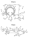
- Figure 5 shows a further embodiment of a dryer section, in which the Material web 14 between the deck screen 18 and the bottom screen 22 via a plurality of arranged on a circular support rollers 38 is.
- the open, the removal of the material web 14 and the deck screen 18 relieving open support surface is again in this case formed by the lower sieve 22.
- the material web 14 thus again between the two screens 18 and 22 on the here Impingement dryer 16 arranged at the top.
- the bottom wire 22 can in principle also be omitted. Instead, can the open support surface through the surface or a cover or covering of the support roller 20 in question. So can on the subject Back-up roller 20, for example, a shrinking screen or the like applied , or the support roller 20 in question can be coated with a Surface.
- the respective backup roller can, for example have a solid shell or spoke / grid construction and also be a polygon.
- the support can be seen, for example, from FIG also done by a variety of small support rollers 38 that are on are arranged in a circular arc so that the curvature of the material web 14 between the screens 18, 22 remains approximately constant.
- the illustrated Embodiments can also be installed in the Main evaporation zone or in the final part of the dryer section in question 12 can be used, which also applies to the remaining ones, which are described below Embodiments apply.
- Figure 6 shows an embodiment of a dryer section 14, in which several overhead impingement dryer 16 a common support band 40 opposite, over which the material web 14 together with a deck sieve 18 formed by a drying sieve is guided.
- the support belt 40 guided over a plurality of support rollers 38 becomes a relevant one Back-up roller 20 (cf. the previous exemplary embodiments) replaced.
- the material web 14 is again in a closed guide in the area a suction roll 32 from a press felt 30 of the press section 10 taken over and fed to the support belt 40 through the deck screen 18.
- three impingement flow dryers 16 are provided, whereby the material web 14 in the area of these impingement dryer 16 each is straight or slightly curved.
- effecting one-sided impingement drying has the material web 14 following the last impingement dryer 16 for example a drying content of about 60% reached.
- the open support surface which enables easier removal, is described in the present case Case by a correspondingly open, i.e. not closed Surface of the support band 40 is formed.
- This support band 40 can for example through a metal band, a foil or an air impermeable Tissue be formed. Compared to a backup roller, the support belt brings 40 and others the advantage with it that it is easier to manufacture and easier is transportable.
- This support band 40 should be so stable that when the impingement flow dryer 16 does not swing.
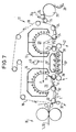
- FIG. 7 shows an embodiment of the dryer section 14 with two at the top lying impingement dryer 16, each one lying below large backup roller 20 are assigned, and with two arranged in between, impingement driers 16 ', 16' 'for a bilateral loading of the material web 14, the material web 14 straight between the two superimposed impingement flow dryers 16 ', 16' 'is passed through.
- the material web 14 is again in the area of a suction roll 32 porous shroud 18 made of metal or plastic from a press felt 30 Press section 10 taken over and in the area of another suction roll 32 fed to the front large backup roller 20, from which they together removed with the deck screen 18 in the area of a further suction roller 24 is then between the deck screen 18 and a another sieve belt 42 made of metal or plastic along a straight line Path between the two superimposed impingement flow dryers 16 ', 16' 'to be passed through.
- the deck screen 18 is both on the front and the rear large backup roller 20 out.
- Backing rolls 20 become the material web through the two impingement flow dryers 16 each dried from above.
- the two support rollers 20 act each one is a grated, covered with a sieve stocking Backup roller.
- the diameter of these support rollers 20 can in particular be larger than about 2 m.
- the large support rollers 20 can be pressurized from the inside with compressed air be to blow off the material web 14 at the respective take-off point to effect.
- the front is considered in the web running direction L.
- Back-up roller 20 internally pressurized, while at rear large backup roller 20 such an internal pressurization is provided only locally, namely in the acceptance area.
- the bottom, not from Decksieb 18 covered area of the front support roller a cover 44 provided by the compressed air flow supporting the decrease is focused on the acceptance area.
- the transfer zone is, for example about 500 mm wide.
- the compressed air temperature is, for example greater than about 20 ° C.
- the material web 14 first on a large support roller 20, then on a light one curved support surface and then again on a large support roller 20 dried.
- To form the slightly curved support surface is a also over the two large support rollers 20 guided deck screen 18 over a plurality of support rollers 38 lying in a correspondingly curved plane guided.
- the two impingement flow dryers 16 are each below the support roller 20 arranged. Through these two impingement flow dryers 16, the material web 14 is thus dried from below.
- an overhead baffle dryer 16 '' ' is provided, which is arranged above the support rollers 38 and consequently for one Drying of the material web 14 ensures from above.
- Level support rollers 38 are provided in a correspondingly curved. Different from the case The exemplary embodiment according to FIG. 7 takes place in the present case from no drying on the side of the support rollers 38. In contrast, Embodiment according to FIG. 7 also on the side of the support rollers 38 an impingement flow dryer 16 '' is provided. In this embodiment 7, the support rollers 38 located below are also in one Level arranged.
- the support rollers 20 are again by grating support rollers covered with a respective screen stocking formed, the diameter of which can be larger than about 2 m.
- a respective the internal blow box assigned to the support rollers 20 is used again web separation and screen cleaning.
- a local pressurization is provided on the front support roller 20, while the rear backup roller 20 overall with pressure inside is applied.
- the rear is in the present case Back-up roller 20 assigned a cover 44 to the compressed air flow to focus accordingly on the acceptance area.
- the compressed air temperature can be greater than about 20 ° C, for example.
- the material web 14 is again through a drying wire 34 from the deck wire 18 removed and a single-tier dryer group of several Drying cylinders 26 supplied with associated suction rolls 28.
- the two large support rollers 20th each supplied with compressed air via a common compressed air source 46.
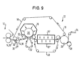
- Figure 9 shows a further embodiment of a dryer section 14, in which the web of material 14 following the press section 10 initially to one-sided drying by an overhead flow dryer 16 over a lower one, which is wrapped by a lower sieve 22 large backup roller 20 and then straight for drying on both sides between two superimposed impact flow dryers 16 ', 16' 'is passed through. Between the two one-sided Impingement dryer 16 ', 16' 'serving for drying is the material web 14 between the deck screen, which is also guided over the support roller 20 18 and another sieve belt 48.
- the material web 14 After transfer from the press section 10 and drying on the large backup roller 20 through the overhead baffle dryer 16, the material web 14 is thus in a rectilinear area, for example can also be slightly curved, due to two superimposed ones Impingement dryer 16 ', 16' 'from both sides, for example simultaneously dried to a dry content of 55 to about 70%.
- Impingement dryer 16 ', 16' 'from both sides for example simultaneously dried to a dry content of 55 to about 70%.
- a single, the material web overlapping and accordingly acting on both sides Dryer may be provided.
- the material web 14 is always from supports at least one fabric so that it never has a smooth surface must be deducted. Then the material web 14 is again one of several drying cylinders 26 with associated suction rolls 28 comprehensive dryer group supplied.
- the deck screen 18 is also through the area between the two superimposed impingement flow dryers 16 ', 16 '' passed through.
- the further sieve belt 48 is fed as a support sieve.
- the material web 14 can also have two new screens be handed over.
- On the side of the sieve belt 48 can again several back-up rollers can be provided.
- the dryer section is therefore especially a supported, draftless one Web guidance up to about 60% to about 70% dryness, for example possible, which eliminates the previous demolition problems in this area are. There are higher drying rates possible, which means a corresponding shorter and more compact dryer section is achieved. Negatives Effects on paper properties are practically impossible.
- the impingement flow dryer can in particular after pressing with subsequent single-row dryer groups can be used. If necessary the described variants can be used until the end of the dryer section expand. In principle, however, the impingement flow dryer is also used conceivable in a main evaporation zone of the dryer section. The use of impingement flow dryers is also fundamentally conceivable in connection with multi-row dryer groups.
Landscapes
- Drying Of Solid Materials (AREA)
- Paper (AREA)
Applications Claiming Priority (2)
| Application Number | Priority Date | Filing Date | Title |
|---|---|---|---|
| DE19841768A DE19841768A1 (de) | 1998-09-11 | 1998-09-11 | Trockenpartie |
| DE19841768 | 1998-09-11 |
Publications (3)
| Publication Number | Publication Date |
|---|---|
| EP0989232A2 true EP0989232A2 (fr) | 2000-03-29 |
| EP0989232A3 EP0989232A3 (fr) | 2001-01-10 |
| EP0989232B1 EP0989232B1 (fr) | 2004-04-28 |
Family
ID=7880733
Family Applications (1)
| Application Number | Title | Priority Date | Filing Date |
|---|---|---|---|
| EP99112926A Expired - Lifetime EP0989232B1 (fr) | 1998-09-11 | 1999-07-05 | Section de séchage |
Country Status (3)
| Country | Link |
|---|---|
| US (1) | US6294050B1 (fr) |
| EP (1) | EP0989232B1 (fr) |
| DE (2) | DE19841768A1 (fr) |
Cited By (4)
| Publication number | Priority date | Publication date | Assignee | Title |
|---|---|---|---|---|
| US7036242B2 (en) | 2000-11-06 | 2006-05-02 | Metso Paper, Inc. | Impingement drying unit and a dryer section |
| WO2006051005A1 (fr) | 2004-11-12 | 2006-05-18 | Voith Patent Gmbh | Train de sechage |
| EP1715099A1 (fr) * | 2005-04-19 | 2006-10-25 | Voith Patent GmbH | Dispositif pour la fabrication d'une bande fibreuse |
| EP1749927A1 (fr) * | 2005-08-05 | 2007-02-07 | Voith Patent GmbH | Dispositif d'essorage d'une bande fibreuse |
Families Citing this family (16)
| Publication number | Priority date | Publication date | Assignee | Title |
|---|---|---|---|---|
| FI113285B (sv) * | 1998-09-04 | 2004-03-31 | Equitor Oy | Förfarande och torkparti för en fiberbanas avvattning |
| EP1072722B1 (fr) * | 1999-07-27 | 2004-12-01 | Voith Paper Patent GmbH | Section de séchage |
| US6447640B1 (en) * | 2000-04-24 | 2002-09-10 | Georgia-Pacific Corporation | Impingement air dry process for making absorbent sheet |
| DE50110918D1 (de) | 2000-05-24 | 2006-10-19 | Voith Patent Gmbh | Trockenpartie |
| DE10025560A1 (de) * | 2000-05-24 | 2001-12-06 | Voith Paper Patent Gmbh | Trockenpartie |
| DE10042243A1 (de) | 2000-08-28 | 2002-03-14 | Voith Paper Patent Gmbh | Verfahren zur Bahnrißüberwachung |
| DE10109525A1 (de) * | 2001-02-28 | 2002-09-05 | Voith Paper Patent Gmbh | Prallströmtrockner |
| FI120366B (fi) * | 2002-03-19 | 2009-09-30 | Metso Paper Inc | Menetelmä ja laitteisto käyttövoiman tuottamiseksi paperi- tai kartonkilaitoksessa |
| US8261465B2 (en) | 2002-09-10 | 2012-09-11 | Voith Paper Patent Gmbh | Equipment and method for producing and/or treating a fibrous web |
| DE10241944A1 (de) * | 2002-09-10 | 2004-03-18 | Voith Paper Patent Gmbh | Einrichtung und Verfahren zur Herstellung und/oder Behandlung einer Faserstoffbahn |
| EP1697584A1 (fr) | 2003-11-28 | 2006-09-06 | Voith Paper Patent GmbH | Machine a papier |
| US7294239B2 (en) * | 2004-01-30 | 2007-11-13 | Voith Paper Patent Gmbh | Method and an apparatus for manufacturing and drying a fiber web provided with a three-dimensional surface structure |
| DE102004023321A1 (de) | 2004-05-07 | 2005-11-24 | Voith Paper Patent Gmbh | Trockenpartie in einer Maschine zur Herstellung einer Faserstoffbahn |
| DE102006015796A1 (de) * | 2005-05-13 | 2006-11-16 | Voith Patent Gmbh | Trockenzylinder |
| DE102006008808A1 (de) * | 2006-02-25 | 2007-08-30 | Voith Patent Gmbh | Verfahren und Vorrichtung zum Befeuchten einer Faserstoffbahn |
| DE102020111746A1 (de) | 2020-04-30 | 2021-11-04 | Voith Patent Gmbh | Maschine zur herstellung oder behandlung einer faserstoffbahn |
Family Cites Families (26)
| Publication number | Priority date | Publication date | Assignee | Title |
|---|---|---|---|---|
| GB1127766A (en) | 1964-10-27 | 1968-09-18 | Pulp Paper Res Inst | Drying process |
| US3303576A (en) * | 1965-05-28 | 1967-02-14 | Procter & Gamble | Apparatus for drying porous paper |
| US3447247A (en) | 1967-12-18 | 1969-06-03 | Beloit Corp | Method and equipment for drying web material |
| GB1264992A (fr) * | 1968-02-15 | 1972-02-23 | ||
| US3851407A (en) * | 1970-10-20 | 1974-12-03 | Ahlstroem Oy | Drying apparatus for a wrinkled paper web |
| CH545659A (fr) * | 1970-12-09 | 1974-02-15 | ||
| US3919783A (en) | 1971-03-29 | 1975-11-18 | Anthony J Cirrito | Method for hot gas heat transfer, particularly for paper drying |
| DE2203621C3 (de) * | 1972-01-26 | 1979-05-17 | Maschinenfabrik Andritz Ag, Graz (Oesterreich) | Vorrichtung zum Trocknen von Materialbahnen |
| DE2364346C3 (de) * | 1973-12-22 | 1978-04-06 | J.M. Voith Gmbh, 7920 Heidenheim | Trockeneinrichtung für Papierbahnen o.dgl |
| US4036684A (en) * | 1975-08-04 | 1977-07-19 | Beloit Corporation | High bulk tissue forming and drying apparatus |
| US4297794A (en) * | 1977-08-02 | 1981-11-03 | Ingersoll-Rand Company | Paper sheet dryer |
| AT355907B (de) * | 1977-08-26 | 1980-03-25 | Albin F Ing Zwach | Streifen-trockenhaube |
| US4361466A (en) * | 1977-10-27 | 1982-11-30 | Beloit Corporation | Air impingement web drying method and apparatus |
| GB2099970B (en) * | 1981-04-27 | 1985-12-11 | Kimberly Clark Ltd | Drying paper webs |
| DE3615152A1 (de) * | 1986-05-05 | 1987-11-12 | Pierkes Heinz Willi | Trockenpartie einer papiermaschine |
| DE3807858A1 (de) * | 1988-03-10 | 1989-09-21 | Voith Gmbh J M | Verfahren zum trocknen einer materialbahn und vorrichtung zur durchfuehrung dieses verfahrens |
| FI87669C (fi) | 1992-03-02 | 1993-02-10 | Valmet Paper Machinery Inc | Foerfarande och tork vid torkning av papper |
| FI102624B1 (fi) * | 1994-06-23 | 1999-01-15 | Valmet Corp | Menetelmä ja laite paperiradan tai vastaavan kuivatuksessa tai jäähdytyksessä |
| FI102623B (fi) * | 1995-10-04 | 1999-01-15 | Valmet Corp | Menetelmä ja laite paperikoneessa |
| US5678321A (en) | 1995-09-12 | 1997-10-21 | Beloit Technologies, Inc. | Air caps for two tier double felted dryer |
| US5933977A (en) | 1995-09-12 | 1999-08-10 | Beloit Technologies, Inc. | Curl control with dryer aircaps |
| US6004430A (en) | 1995-10-04 | 1999-12-21 | Ilvespaa; Heikki | Method and device for enhancing the run of a paper web in a paper machine |
| FI972063A7 (fi) * | 1996-05-15 | 1997-11-16 | Voith Sulzer Papiermasch Gmbh | Laitteisto materiaalirainan valmistamiseksi |
| DE19642526A1 (de) * | 1996-10-15 | 1998-04-16 | Voith Sulzer Papiermasch Gmbh | Trockenpartie |
| DE19651191A1 (de) * | 1996-12-10 | 1998-06-18 | Voith Sulzer Papiermasch Gmbh | Trockenpartie einer Maschine zur Herstellung einer Materialbahn |
| FI104001B1 (fi) * | 1998-06-26 | 1999-10-29 | Valmet Corp | Kuivatusosa |
-
1998
- 1998-09-11 DE DE19841768A patent/DE19841768A1/de not_active Withdrawn
-
1999
- 1999-07-05 EP EP99112926A patent/EP0989232B1/fr not_active Expired - Lifetime
- 1999-07-05 DE DE59909306T patent/DE59909306D1/de not_active Expired - Fee Related
- 1999-09-10 US US09/393,691 patent/US6294050B1/en not_active Expired - Fee Related
Cited By (5)
| Publication number | Priority date | Publication date | Assignee | Title |
|---|---|---|---|---|
| US7036242B2 (en) | 2000-11-06 | 2006-05-02 | Metso Paper, Inc. | Impingement drying unit and a dryer section |
| WO2006051005A1 (fr) | 2004-11-12 | 2006-05-18 | Voith Patent Gmbh | Train de sechage |
| EP1715099A1 (fr) * | 2005-04-19 | 2006-10-25 | Voith Patent GmbH | Dispositif pour la fabrication d'une bande fibreuse |
| EP1749927A1 (fr) * | 2005-08-05 | 2007-02-07 | Voith Patent GmbH | Dispositif d'essorage d'une bande fibreuse |
| US7628891B2 (en) | 2005-08-05 | 2009-12-08 | Voith Patent Gmbh | Apparatus for dewatering a fibrous web |
Also Published As
| Publication number | Publication date |
|---|---|
| EP0989232A3 (fr) | 2001-01-10 |
| DE19841768A1 (de) | 2000-03-16 |
| US6294050B1 (en) | 2001-09-25 |
| DE59909306D1 (de) | 2004-06-03 |
| EP0989232B1 (fr) | 2004-04-28 |
Similar Documents
| Publication | Publication Date | Title |
|---|---|---|
| EP0989232B1 (fr) | Section de séchage | |
| EP1770209B1 (fr) | Procédé et dispositif pour la production d'une bande de papier tissu | |
| EP0988417B1 (fr) | Secherie | |
| DE69019728T2 (de) | Vorrichtung zum Trocknen einer Bahn. | |
| DE4015942C1 (fr) | ||
| EP1072722B1 (fr) | Section de séchage | |
| EP0989233B1 (fr) | Section de séchage et sécheur à convection pour une telle section de séchage | |
| DE4416585A1 (de) | Trockenpartie einer Papiermaschine | |
| EP1156155B1 (fr) | Section de séchage d'une machine de fabrication de papier ou carton | |
| DE69617522T2 (de) | Trockenpartie mit einer Kombination von Einsieb- und Doppelsiebtrockengruppen | |
| DE4201107C2 (de) | Trockenpartie | |
| EP3987113B1 (fr) | Machine destinée à la fabrication d'une bande de matière fibreuse | |
| EP1158092B1 (fr) | Section de séchage | |
| DE19935138A1 (de) | Trockenpartie | |
| EP2003243B1 (fr) | Partie sèche | |
| DE19548307A1 (de) | Trockenpartie | |
| EP3833816B1 (fr) | Système de presse | |
| DE19944266A1 (de) | Verfahren zum Trocknen einer Materialbahn | |
| DE19602492C2 (de) | Maschine zur Herstellung einer Papier- oder Kartonbahn | |
| DE29823738U1 (de) | Trockenpartie | |
| DE19654434A1 (de) | Maschine zur Herstellung einer kontinuierlichen Materialbahn | |
| EP1586700B1 (fr) | Machine à papier | |
| DE102009027608A1 (de) | Trockenpartie | |
| DE29924874U1 (de) | Trockenpartie | |
| DE102004027938A1 (de) | Trockenpartie |
Legal Events
| Date | Code | Title | Description |
|---|---|---|---|
| PUAI | Public reference made under article 153(3) epc to a published international application that has entered the european phase |
Free format text: ORIGINAL CODE: 0009012 |
|
| AK | Designated contracting states |
Kind code of ref document: A2 Designated state(s): DE FI SE |
|
| AX | Request for extension of the european patent |
Free format text: AL;LT;LV;MK;RO;SI |
|
| PUAL | Search report despatched |
Free format text: ORIGINAL CODE: 0009013 |
|
| RAP1 | Party data changed (applicant data changed or rights of an application transferred) |
Owner name: VOITH PAPER PATENT GMBH |
|
| AK | Designated contracting states |
Kind code of ref document: A3 Designated state(s): AT BE CH CY DE DK ES FI FR GB GR IE IT LI LU MC NL PT SE |
|
| AX | Request for extension of the european patent |
Free format text: AL;LT;LV;MK;RO;SI |
|
| 17P | Request for examination filed |
Effective date: 20010710 |
|
| AKX | Designation fees paid |
Free format text: DE FI SE |
|
| 17Q | First examination report despatched |
Effective date: 20020913 |
|
| GRAP | Despatch of communication of intention to grant a patent |
Free format text: ORIGINAL CODE: EPIDOSNIGR1 |
|
| GRAS | Grant fee paid |
Free format text: ORIGINAL CODE: EPIDOSNIGR3 |
|
| GRAA | (expected) grant |
Free format text: ORIGINAL CODE: 0009210 |
|
| AK | Designated contracting states |
Kind code of ref document: B1 Designated state(s): DE FI SE |
|
| REF | Corresponds to: |
Ref document number: 59909306 Country of ref document: DE Date of ref document: 20040603 Kind code of ref document: P |
|
| REG | Reference to a national code |
Ref country code: SE Ref legal event code: TRGR |
|
| PLBE | No opposition filed within time limit |
Free format text: ORIGINAL CODE: 0009261 |
|
| STAA | Information on the status of an ep patent application or granted ep patent |
Free format text: STATUS: NO OPPOSITION FILED WITHIN TIME LIMIT |
|
| 26N | No opposition filed |
Effective date: 20050131 |
|
| PGFP | Annual fee paid to national office [announced via postgrant information from national office to epo] |
Ref country code: SE Payment date: 20060713 Year of fee payment: 8 |
|
| EUG | Se: european patent has lapsed | ||
| PG25 | Lapsed in a contracting state [announced via postgrant information from national office to epo] |
Ref country code: SE Free format text: LAPSE BECAUSE OF NON-PAYMENT OF DUE FEES Effective date: 20070706 |
|
| PGFP | Annual fee paid to national office [announced via postgrant information from national office to epo] |
Ref country code: FI Payment date: 20090715 Year of fee payment: 11 Ref country code: DE Payment date: 20090722 Year of fee payment: 11 |
|
| PG25 | Lapsed in a contracting state [announced via postgrant information from national office to epo] |
Ref country code: DE Free format text: LAPSE BECAUSE OF NON-PAYMENT OF DUE FEES Effective date: 20110201 |
|
| REG | Reference to a national code |
Ref country code: DE Ref legal event code: R119 Ref document number: 59909306 Country of ref document: DE Effective date: 20110201 |
|
| PG25 | Lapsed in a contracting state [announced via postgrant information from national office to epo] |
Ref country code: FI Free format text: LAPSE BECAUSE OF NON-PAYMENT OF DUE FEES Effective date: 20100705 |