EP0989232A2 - Drying section - Google Patents
Drying section Download PDFInfo
- Publication number
- EP0989232A2 EP0989232A2 EP99112926A EP99112926A EP0989232A2 EP 0989232 A2 EP0989232 A2 EP 0989232A2 EP 99112926 A EP99112926 A EP 99112926A EP 99112926 A EP99112926 A EP 99112926A EP 0989232 A2 EP0989232 A2 EP 0989232A2
- Authority
- EP
- European Patent Office
- Prior art keywords
- dryer
- section according
- dryer section
- material web
- impingement
- Prior art date
- Legal status (The legal status is an assumption and is not a legal conclusion. Google has not performed a legal analysis and makes no representation as to the accuracy of the status listed.)
- Granted
Links
Images


Classifications
-
- D—TEXTILES; PAPER
- D21—PAPER-MAKING; PRODUCTION OF CELLULOSE
- D21F—PAPER-MAKING MACHINES; METHODS OF PRODUCING PAPER THEREON
- D21F5/00—Dryer section of machines for making continuous webs of paper
- D21F5/18—Drying webs by hot air
- D21F5/182—Drying webs by hot air through perforated cylinders
-
- D—TEXTILES; PAPER
- D21—PAPER-MAKING; PRODUCTION OF CELLULOSE
- D21F—PAPER-MAKING MACHINES; METHODS OF PRODUCING PAPER THEREON
- D21F5/00—Dryer section of machines for making continuous webs of paper
-
- D—TEXTILES; PAPER
- D21—PAPER-MAKING; PRODUCTION OF CELLULOSE
- D21F—PAPER-MAKING MACHINES; METHODS OF PRODUCING PAPER THEREON
- D21F5/00—Dryer section of machines for making continuous webs of paper
- D21F5/18—Drying webs by hot air
Definitions
- the invention relates to a dryer section of a machine for production a material web, in particular a paper or cardboard web.
- the aim of the invention is to provide a dryer section of the type mentioned to create, with at the same time as optimal as possible Drying rate and thus the smallest possible total length of the Drying section possible as well as a safe web guide is guaranteed.
- This object is achieved according to the invention in that it at least comprises a baffle dryer through which the web of material at least on one side with a hot air and / or hot steam impingement flow is acted upon.
- the drying section is the material web with its one through each Impingement flow side opposite side via a open, i.e. not smooth support surface led. This means that the still relatively moist material web of the support surface remains stuck, so that the risk of web breaks and overstretching of the web edges is practically excluded.
- At least one impingement flow dryer with one is expedient steam evacuation for simultaneous evaporation.
- the material web can advantageously together with an intermediate you and the relevant impact flow dryer deck sieve be guided over the support surface.
- the web of material is thus removed from the deck screen supported. Through this deck screen, the material web is on the support surface held and transported in the event of a possible demolition, so that no rejects get caught in the respective impingement dryer can.
- the dryer section is characterized in that the material web has a guided larger backup roller in particular and the open support surface either through the surface or a cover or covering of the support roller or through the surface of an endless belt guided over the support roller is formed.
- the relatively large back-up roller ensures safe and precise guidance with constant radius of curvature. After the backup roller is not more than pressure vessel must be made, it can be relatively large, to provide a correspondingly larger drying area.
- the backup roller can have an outer diameter in the range, for example from about 2 to about 10 m.
- this endless belt can in particular be formed by an air-permeable sieve. Basically this is however, for example, the use of an airtight Conveyor belt conceivable.
- the open support surface can, for example formed by a shrink screen applied to the support roller his.
- Drying section is the open support surface through the surface of a formed over several support rollers support band.
- the open support surface can be guided at least in sections, e.g. over a variety of support rollers.
- sections e.g. over a variety of support rollers.
- the support rollers are on one Arranged circular arc.
- the support band can in particular also be polygonal.
- the material web at least in the removal area through the Compressed air must be applied through the support surface.
- a support roller this can for example provided with a grid structure or perforated and on the inside at least partially pressurized with compressed air or the like his.
- a backup roller can then at least in the removal area, in which the material web and possibly also a deck screen from the backup roller is removed, be pressurized on the inside.
- the temperature of the compressed air is expediently higher than about 20 ° C.
- Impingement flow dryer provided that a hot air or hot steam impingement flow with a temperature in the range of about 150 ° to about 450 ° C generated.
- At least one impingement flow dryer with a plurality used by high performance nozzles these high performance nozzles expediently an equal constant distance during operation own from the material web.
- This distance can be, for example are in the range of about 10 to about 50 mm.
- At least one impingement flow dryer with at least one provided a dryer hood, such a dryer hood advantageously in the direction of web travel and / or transverse to the web direction in Zones can be divided.
- a dryer hood advantageously in the direction of web travel and / or transverse to the web direction in Zones can be divided.
- At least one impingement flow dryer can be in an initial area, for example the dryer section can be provided. Additionally or alternatively can at least one such impingement flow dryer also in a main evaporation zone the dryer section can be provided. Additionally or alternatively can also be at least one in an end region of the dryer section Impingement dryer can be provided. This results in one more higher drying rate, which further shortens the drying section overall becomes.
- a deck screen through both a backup roll impingement dryer as well as an adjoining one straight or slightly curved impingement dryer unit respectively.
- the straight impingement dryer unit can, for example a second sieve can be fed as a support sieve.
- the Paper web for example, can also be transferred to two new screens.
- the Material web for example, also on both sides of a respective hot air or Hot steam impingement flow must be applied.
- one straight or slightly curved path guidance can for example a corresponding impingement flow dryer is also provided on only one side be while on the opposite side for example a plurality of support rollers can be arranged.
- the material web is subjected to a hot air or hot steam impingement flow from one side, on which a large number is arranged by support rollers.
- the application is made especially through the area between the support rollers through it.
- the material web can be at different points from the same side or from different sides with one respective hot air or hot steam impingement flow are applied.
- FIGS. 1 to 9 there is in each case one adjoining a press section 10 Section of a dryer section 12 shown as well the press section to a machine for producing a material web 14, here a paper or cardboard web, belongs.
- the dryer section 12 comprises one Impingement dryer 16 located above, through which the material web 14 one-sided with a hot air and / or hot steam impingement flow is applied.
- the material web 14 is with the impingement dryer 16 opposite side via an open, i.e. not smooth support surface guided.
- the material web 14 together with a deck screen 18 guided over a larger backup roller 20 by a bottom wire 20 is wrapped around, which forms the open support surface in the present case.
- This endless belt or bottom wire 22 consequently becomes the subsequent one Removal of the material web 14 and the deck screen 18 facilitated.
- the material web is in the removal area behind the large support roller 20 14 together with the deck screen 18 around a suction roll 24, whereupon a single-tier dryer group with multiple dryer cylinders 26 and intermediate suction rolls 28 is supplied.
- the deck screen 18 in the area of first drying cylinder 26 again separated from the material web 14.
- the material web 14 is in a closed train from the last press nip of the press section 10 to the impingement dryer 16 transferred.
- the material web 14 is supported by the deck screen 18 and led to the large support roller 20 on which the lower wire 22 runs.
- the large back-up roller 20 ensures safe and exact guidance of the two screens 18, 22 with intermediate material web 14 at constant Radius of curvature. As a result, and as a result of the minimal required Screen tension is damage to the material web 14 locked out.
- the support roller 20 no longer has to be designed as a pressure vessel and can therefore be much larger, making a larger one Drying area is provided.
- the deck screen 18 is expediently particularly open, thin and resistant to high temperatures, to enable good impingement drying. Its job is to hold the material web 14 on the support roller 20 and also at one Transporting demolition further, so that there is no committee in the several high-performance nozzles provided dryer hood of the impingement flow dryer 16 can catch.
- the bottom wire 22 allows a simple one Removal of the material web 14 from the support roller 20. It does not have to be as open as the deck screen 18, but should still be impermeable to air his. Both screens 18, 22 can be cleaned in the return.
- the dryer hood of the impingement dryer 16 can in longitudinal zones be divided and have transverse zones for moisture profile correction.
- the Dryer hood should be divided as possible so that it from the backup roller 20 can be lifted off.
- the high-performance nozzles are in operation a constant distance from the surface of the material web 14, wherein this distance, for example, in a range from about 10 to about 50 mm may lie.
- the material web 14 of a press felt 30 Press section 10 supported in the closed train by the deck screen 18 the support roller 20 fed, the deck screen 18 both in the area the takeover of the material web 14 from the press felt 30 as well in the area of the transfer of the material web 14 to the support roller 20 is guided over a suction roller 32.
- the material web 14 to be dried is accordingly following the Press section 10 between two open temperature-resistant screens 18, 22 guided around a large support roller 20, on which the with high-performance nozzles provided drying hood of an impingement dryer 16 installed is.
- the flow rate of the hot air and / or Hot steam impingement flow can range, for example, from about 60 to about 120 m / s.
- the temperature of this baffle can for example in a range from about 150 to about 450 ° C.
- gas or steam heaters is fundamentally Hot air or superheated steam possible.
- the drying performance without extending the dryer section can be such Backing roll impingement dryer 16 alternatively or additionally for example also in the final part of the dryer section 12 and / or in the Main evaporation zone must be installed.
- the more flexible and quicker adjustable baffle hood divided into longitudinal and transverse zones enables the paper quality to be influenced. So in particular a targeted heating and drying at the beginning and a Correction of moisture cross profiles possible.
- the cross shrinkage hindrance can be varied within limits by the screen tension, since no pressing more is required on heating surfaces.
- the deck screen 18 can be made of plastic or metal, for example.
- the bottom wire 22 can be replaced by an impermeable conveyor belt become.
- the transfer of the material web 14 from the press section 10 to the impingement flow dryer can, in addition to through the deck screen 18 additionally supported by a transfer foil or with an additional one Transfer felt 36 take place, as indicated, for example, in FIG. 3 is.
- a respective drying hood can also use superheated steam operate.
- the Roller jacket can be cooled via coolant channels or from the inside.
- Endless belt 22 can then have multiple layers with a coarser structure be carried out on the roller side to remove condensed water.
- the material web is lifted off 14 from the deck screen 18 during transfer to and removal from the impingement dryer 16 prevented by suction rollers 32 and 24 respectively.
- suction rollers 32 and 24 For this grooved rollers or transfer foils can also be provided.
- FIG. 2 shows a further embodiment of a dryer section 14 with two impact flow dryers opposite a respective larger support roller 20 16, through which the material web of different Sides is applied.
- L looks at front baffle dryer 16 above and the rear impingement dryer 16 arranged below.
- Each of these two backup rolls is, for example again wrapped in a lower sieve 22.
- the material web 14 is each again together with a deck screen 18 over the large one in question Backup roller 20 out.
- the material web becomes from the rear deck screen 18 14 finally taken over by a drying wire 34.
- On the other hand 1 is the only one provided there in the exemplary embodiment according to FIG Decksieb 18 separated from the material web 14 before this with the Dryer screen 34 is merged. Between the press section 10 and the front support roller 20 is supported by the deck screen 18 Material web 14 is only guided over a single suction roller 32.
- the drying section 14 following the press section 10 again two each large back-up roller 20 assigned, the material web 14 from differing Impingement dryer 16 acting on the sides 16.
- the front impingement dryer viewed in the web running direction L 16 below and the rear impingement dryer 16 above arranged.
- the front large support roller 20 lies above and the rear large backup roller 20 below.
- the front backup roller 20 has a smaller diameter than the rear one Back-up roller 20.
- the material web finally becomes from this transfer felt 36 taken over by the deck screen 18 guided over the front support roller 20, this deck screen 18 in the takeover area over a Suction roller 32 is guided.
- FIG. 2 also shows the material web 14 in the present case the front backup roller 20 guided deck screen in the area of two suction rollers 24 passed to the deck screen 18 guided over the rear support roller 20.
- the two large support rollers 20 in each case, for example, again wrapped in a lower sieve 22. While in the exemplary embodiment according to FIG.
- the two large support rollers 20 are each again, for example, from wrapped around a lower sieve 22.
- FIG. 4 shows an embodiment of a dryer section 14 with two ones respective lower large backup roller 20 associated upper impingement dryer 16 through which the material web 14 from the same side is applied here. As can be seen in FIG. 4, is about the two lower support rollers 20 guided a common deck screen 18. The two support rollers 20 are each one of the open support surface forming lower sieve 22 wrapped.
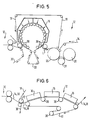
- Figure 5 shows a further embodiment of a dryer section, in which the Material web 14 between the deck screen 18 and the bottom screen 22 via a plurality of arranged on a circular support rollers 38 is.
- the open, the removal of the material web 14 and the deck screen 18 relieving open support surface is again in this case formed by the lower sieve 22.
- the material web 14 thus again between the two screens 18 and 22 on the here Impingement dryer 16 arranged at the top.
- the bottom wire 22 can in principle also be omitted. Instead, can the open support surface through the surface or a cover or covering of the support roller 20 in question. So can on the subject Back-up roller 20, for example, a shrinking screen or the like applied , or the support roller 20 in question can be coated with a Surface.
- the respective backup roller can, for example have a solid shell or spoke / grid construction and also be a polygon.
- the support can be seen, for example, from FIG also done by a variety of small support rollers 38 that are on are arranged in a circular arc so that the curvature of the material web 14 between the screens 18, 22 remains approximately constant.
- the illustrated Embodiments can also be installed in the Main evaporation zone or in the final part of the dryer section in question 12 can be used, which also applies to the remaining ones, which are described below Embodiments apply.
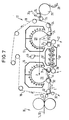
- Figure 6 shows an embodiment of a dryer section 14, in which several overhead impingement dryer 16 a common support band 40 opposite, over which the material web 14 together with a deck sieve 18 formed by a drying sieve is guided.
- the support belt 40 guided over a plurality of support rollers 38 becomes a relevant one Back-up roller 20 (cf. the previous exemplary embodiments) replaced.
- the material web 14 is again in a closed guide in the area a suction roll 32 from a press felt 30 of the press section 10 taken over and fed to the support belt 40 through the deck screen 18.
- three impingement flow dryers 16 are provided, whereby the material web 14 in the area of these impingement dryer 16 each is straight or slightly curved.
- effecting one-sided impingement drying has the material web 14 following the last impingement dryer 16 for example a drying content of about 60% reached.
- the open support surface which enables easier removal, is described in the present case Case by a correspondingly open, i.e. not closed Surface of the support band 40 is formed.
- This support band 40 can for example through a metal band, a foil or an air impermeable Tissue be formed. Compared to a backup roller, the support belt brings 40 and others the advantage with it that it is easier to manufacture and easier is transportable.
- This support band 40 should be so stable that when the impingement flow dryer 16 does not swing.
- FIG. 7 shows an embodiment of the dryer section 14 with two at the top lying impingement dryer 16, each one lying below large backup roller 20 are assigned, and with two arranged in between, impingement driers 16 ', 16' 'for a bilateral loading of the material web 14, the material web 14 straight between the two superimposed impingement flow dryers 16 ', 16' 'is passed through.
- the material web 14 is again in the area of a suction roll 32 porous shroud 18 made of metal or plastic from a press felt 30 Press section 10 taken over and in the area of another suction roll 32 fed to the front large backup roller 20, from which they together removed with the deck screen 18 in the area of a further suction roller 24 is then between the deck screen 18 and a another sieve belt 42 made of metal or plastic along a straight line Path between the two superimposed impingement flow dryers 16 ', 16' 'to be passed through.
- the deck screen 18 is both on the front and the rear large backup roller 20 out.
- Backing rolls 20 become the material web through the two impingement flow dryers 16 each dried from above.
- the two support rollers 20 act each one is a grated, covered with a sieve stocking Backup roller.
- the diameter of these support rollers 20 can in particular be larger than about 2 m.
- the large support rollers 20 can be pressurized from the inside with compressed air be to blow off the material web 14 at the respective take-off point to effect.
- the front is considered in the web running direction L.
- Back-up roller 20 internally pressurized, while at rear large backup roller 20 such an internal pressurization is provided only locally, namely in the acceptance area.
- the bottom, not from Decksieb 18 covered area of the front support roller a cover 44 provided by the compressed air flow supporting the decrease is focused on the acceptance area.
- the transfer zone is, for example about 500 mm wide.
- the compressed air temperature is, for example greater than about 20 ° C.
- the material web 14 first on a large support roller 20, then on a light one curved support surface and then again on a large support roller 20 dried.
- To form the slightly curved support surface is a also over the two large support rollers 20 guided deck screen 18 over a plurality of support rollers 38 lying in a correspondingly curved plane guided.
- the two impingement flow dryers 16 are each below the support roller 20 arranged. Through these two impingement flow dryers 16, the material web 14 is thus dried from below.
- an overhead baffle dryer 16 '' ' is provided, which is arranged above the support rollers 38 and consequently for one Drying of the material web 14 ensures from above.
- Level support rollers 38 are provided in a correspondingly curved. Different from the case The exemplary embodiment according to FIG. 7 takes place in the present case from no drying on the side of the support rollers 38. In contrast, Embodiment according to FIG. 7 also on the side of the support rollers 38 an impingement flow dryer 16 '' is provided. In this embodiment 7, the support rollers 38 located below are also in one Level arranged.
- the support rollers 20 are again by grating support rollers covered with a respective screen stocking formed, the diameter of which can be larger than about 2 m.
- a respective the internal blow box assigned to the support rollers 20 is used again web separation and screen cleaning.
- a local pressurization is provided on the front support roller 20, while the rear backup roller 20 overall with pressure inside is applied.
- the rear is in the present case Back-up roller 20 assigned a cover 44 to the compressed air flow to focus accordingly on the acceptance area.
- the compressed air temperature can be greater than about 20 ° C, for example.
- the material web 14 is again through a drying wire 34 from the deck wire 18 removed and a single-tier dryer group of several Drying cylinders 26 supplied with associated suction rolls 28.
- the two large support rollers 20th each supplied with compressed air via a common compressed air source 46.
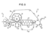
- Figure 9 shows a further embodiment of a dryer section 14, in which the web of material 14 following the press section 10 initially to one-sided drying by an overhead flow dryer 16 over a lower one, which is wrapped by a lower sieve 22 large backup roller 20 and then straight for drying on both sides between two superimposed impact flow dryers 16 ', 16' 'is passed through. Between the two one-sided Impingement dryer 16 ', 16' 'serving for drying is the material web 14 between the deck screen, which is also guided over the support roller 20 18 and another sieve belt 48.
- the material web 14 After transfer from the press section 10 and drying on the large backup roller 20 through the overhead baffle dryer 16, the material web 14 is thus in a rectilinear area, for example can also be slightly curved, due to two superimposed ones Impingement dryer 16 ', 16' 'from both sides, for example simultaneously dried to a dry content of 55 to about 70%.
- Impingement dryer 16 ', 16' 'from both sides for example simultaneously dried to a dry content of 55 to about 70%.
- a single, the material web overlapping and accordingly acting on both sides Dryer may be provided.
- the material web 14 is always from supports at least one fabric so that it never has a smooth surface must be deducted. Then the material web 14 is again one of several drying cylinders 26 with associated suction rolls 28 comprehensive dryer group supplied.
- the deck screen 18 is also through the area between the two superimposed impingement flow dryers 16 ', 16 '' passed through.
- the further sieve belt 48 is fed as a support sieve.
- the material web 14 can also have two new screens be handed over.
- On the side of the sieve belt 48 can again several back-up rollers can be provided.
- the dryer section is therefore especially a supported, draftless one Web guidance up to about 60% to about 70% dryness, for example possible, which eliminates the previous demolition problems in this area are. There are higher drying rates possible, which means a corresponding shorter and more compact dryer section is achieved. Negatives Effects on paper properties are practically impossible.
- the impingement flow dryer can in particular after pressing with subsequent single-row dryer groups can be used. If necessary the described variants can be used until the end of the dryer section expand. In principle, however, the impingement flow dryer is also used conceivable in a main evaporation zone of the dryer section. The use of impingement flow dryers is also fundamentally conceivable in connection with multi-row dryer groups.
Landscapes
- Paper (AREA)
- Drying Of Solid Materials (AREA)
Abstract
Description
Die Erfindung betrifft eine Trockenpartie einer Maschine zur Herstellung einer Materialbahn, insbesondere Papier- oder Kartonbahn.The invention relates to a dryer section of a machine for production a material web, in particular a paper or cardboard web.
Bei den bisher üblichen Mehrzylinder-Trockenpartien wird die Papierbahn zum Trocknen über mehrere dampfbeheizte Zylinder oder über eine Anordnung von mehreren dampfbeheizten Zylindern und Siebsaugwalzen geführt. Insbesondere zu Beginn der Trocknung, wo die Papierbahn noch keine ausreichende Festigkeit besitzt, treten nun aber bezüglich der Bahnführung häufig Probleme auf, die insbesondere darauf zurückzuführen sind, daß die noch feuchte Bahn an den glatten Kontaktflächen kleben bleibt, die für eine hinreichende Wärmeübertragung zwingend notwendig sind. Dies führt häufig zu Bahnabrissen und einer Überdehnung der Bahnränder. Demzufolge muß in der Regel dafür gesorgt werden, daß die Trocknung langsamer erfolgt, was bedeutet, daß die erforderliche Trockenpartie insgesamt länger wird. Die zuvor genannten Probleme treten verstärkt bei höheren Bahngeschwindigkeiten auf.In the previously common multi-cylinder dryer sections, the paper web for drying over several steam-heated cylinders or over an arrangement of several steam-heated cylinders and screen suction rolls guided. Especially at the beginning of drying, where the paper web is still does not have sufficient strength, but now occur with regard to Web routing often has problems that are particularly attributable to it are that the still wet web sticks to the smooth contact surfaces remains, which is absolutely necessary for adequate heat transfer are. This often leads to web breaks and overstretching of the Web edges. As a result, it is usually necessary to ensure that the Drying is slower, which means that the required Dryer section gets longer overall. The aforementioned problems occur intensifies at higher web speeds.
Ziel der Erfindung ist es, eine Trockenpartie der eingangs genannten Art zu schaffen, mit der gleichzeitig sowohl eine möglichst optimale Trocknungsrate und damit eine möglichst geringe Gesamtlänge der Trockenpartie möglich als auch eine sichere Bahnführung gewährleistet ist. The aim of the invention is to provide a dryer section of the type mentioned to create, with at the same time as optimal as possible Drying rate and thus the smallest possible total length of the Drying section possible as well as a safe web guide is guaranteed.
Diese Aufgabe wird nach der Erfindung dadurch gelöst, daß sie wenigstens einen Prallströmungstrockner umfaßt, durch den die Materialbahn zumindest einseitig mit einer Heißluft- und/oder Heißdampfprallströmung beaufschlagbar ist.This object is achieved according to the invention in that it at least comprises a baffle dryer through which the web of material at least on one side with a hot air and / or hot steam impingement flow is acted upon.
Aufgrund dieser Ausbildung ist es nicht mehr erforderlich, die noch relativ feuchte Materialbahn zur Erzielung einer hinreichenden Wärmeübertragung über glatte Kontaktflächen zu führen. Infolge der Vermeidung glatter Kontaktflächen zu Beginn der Trocknung ist die Gefahr von Bahnabrissen sowie einer Überdehnung der Bahnränder praktisch beseitigt. Es sind nunmehr insbesondere auch höhere Trocknungsraten möglich, wodurch sich die Gesamtlänge der Trockenpartie entsprechend verkürzt. Die Trocknungsleistung zu Beginn des Trocknungsvorgangs ist nur noch durch eine Beeinflussung der Papierqualität bei zu hoher Trocknungsgeschwindigkeit begrenzt und nicht mehr durch die Bahnführung der feuchten Papierbahn. Zudem kann mit dem flexibler und schneller regelbaren Prallströmungstrockner die Papierqualität besser beeinflußt werden. So ist zu Beginn der Trocknungsphase mit einer gezielten Aufheizung und Trocknung insbesondere auch eine Korrektur von Feuchtequerprofilen möglich. Nachdem kein Anpressen an Heizflächen mehr erforderlich ist, kann auch eine jeweilige Querschrumpfungsbehinderung besser gesteuert oder variiert werden.Because of this training, it is no longer necessary to be still relative moist material web to achieve sufficient heat transfer to run over smooth contact surfaces. As a result of avoiding smoother Contact areas at the start of drying are the danger of web breaks and overstretching of the web edges practically eliminated. There are higher drying rates are now possible in particular, whereby the total length of the dryer section is shortened accordingly. The Drying performance at the beginning of the drying process is only by influencing the paper quality when the drying speed is too high limited and no longer by the path of the damp paper web. It can also be regulated more flexibly and quickly Impingement dryer the paper quality can be influenced better. So at the beginning of the drying phase with a targeted heating and Drying, especially correction of moisture cross profiles possible. After pressing on heating surfaces is no longer necessary, can also better control each cross shrinkage hindrance or be varied.
Bei einer bevorzugten praktischen Ausführungsform der erfindungsgemäßen Trockenpartie ist die Materialbahn mit ihrer einer jeweils durch eine Prallströmung beaufschlagten Seite gegenüberliegenden Seite über eine offene, d.h. nicht glatte Stützfläche geführt. Damit ist ausgeschlossen, daß die noch relativ feuchte Materialbahn der Stützfläche kleben bleibt, so daß die Gefahr von Bahnabrissen sowie einer Überdehnung der Bahnränder praktisch ausgeschlossen ist.In a preferred practical embodiment of the invention The drying section is the material web with its one through each Impingement flow side opposite side via a open, i.e. not smooth support surface led. This means that the still relatively moist material web of the support surface remains stuck, so that the risk of web breaks and overstretching of the web edges is practically excluded.
Zweckmäßigerweise ist wenigstens ein Prallströmungstrockner mit einer dem gleichzeitigen Ausdampfen dienenden Dampfabsaugung versehen. Demzufolge ist kein Wechsel zwischen Aufheizen und Ausdampfen mehr erforderlich. Mit dem Wegfall der zusätzlichen Ausdampffläche wird die gesamte Lauflänge weiter verringert.At least one impingement flow dryer with one is expedient steam evacuation for simultaneous evaporation. As a result, there is no longer a change between heating up and evaporation required. With the elimination of the additional evaporation surface, the total barrel length further reduced.
Die Materialbahn kann vorteilhafterweise zusammen mit einem zwischen ihr und dem betreffenden Prallströmungstrockner liegenden Decksieb über die Stützfläche geführt sein. Die Materialbahn wird somit vom Decksieb gestützt. Durch dieses Decksieb wird die Materialbahn auf der Stützfläche gehalten und auch bei einem eventuellen Abriß weitertransportiert, so daß sich kein Ausschuß im jeweiligen Prallströmungstrockner verfangen kann.The material web can advantageously together with an intermediate you and the relevant impact flow dryer deck sieve be guided over the support surface. The web of material is thus removed from the deck screen supported. Through this deck screen, the material web is on the support surface held and transported in the event of a possible demolition, so that no rejects get caught in the respective impingement dryer can.
Eine zweckmäßige praktische Ausführungsform der erfindungsgemäßen Trockenpartie zeichnet sich dadurch aus, daß die Materialbahn über eine insbesondere größere Stützwalze geführt und die offene Stützfläche entweder durch die Oberfläche bzw. einen Bezug oder Belag der Stützwalze oder durch die Oberfläche eines über die Stützwalze geführten Endlosbandes gebildet ist.An expedient practical embodiment of the invention The dryer section is characterized in that the material web has a guided larger backup roller in particular and the open support surface either through the surface or a cover or covering of the support roller or through the surface of an endless belt guided over the support roller is formed.
Die relativ große Stützwalze gewährleistet eine sichere und exakte Führung bei konstantem Krümmungsradius. Nachdem die Stützwalze nicht mehr als Druckbehälter ausgeführt sein muß, kann sie relativ groß sein, um eine entsprechend größere Trocknungsfläche zur Verfügung zu stellen. The relatively large back-up roller ensures safe and precise guidance with constant radius of curvature. After the backup roller is not more than pressure vessel must be made, it can be relatively large, to provide a correspondingly larger drying area.
Die Stützwalze kann beispielsweise einen Außendurchmesser im Bereich von etwa 2 bis etwa 10 m besitzen.The backup roller can have an outer diameter in the range, for example from about 2 to about 10 m.
Ist die offene Stützfläche durch die Oberfläche eines über die Stützwalze geführten Endlosbandes gebildet, so kann dieses Endlosband insbesondere durch ein luftdurchlässiges Sieb gebildet sein. Grundsätzlich ist hierbei jedoch beispielsweise auch die Verwendung eines luftundurchlässigen Transportbandes denkbar. Zudem kann die offene Stützfläche beispielsweise durch ein auf die Stützwalze aufgebrachtes Schrumpfsieb gebildet sein.Is the open support surface through the surface of one over the support roller guided endless belt formed, this endless belt can in particular be formed by an air-permeable sieve. Basically this is however, for example, the use of an airtight Conveyor belt conceivable. In addition, the open support surface can, for example formed by a shrink screen applied to the support roller his.
Gemäß einer alternativen vorteilhaften Ausführungsform der erfindungsgemäßen Trockenpartie ist die offene Stützfläche durch die Oberfläche eines über mehrere Stützrollen geführten Stützbandes gebildet.According to an alternative advantageous embodiment of the invention Drying section is the open support surface through the surface of a formed over several support rollers support band.
Insbesondere mit einer solchen Ausführung kann die offene Stützfläche zumindest abschnittsweise auch eben geführt sein, z.B. über eine Vielzahl von Stützrollen. Zudem ist beispielsweise auch eine zumindest abschnittsweise leicht gekrümmte offene Stützfläche denkbar.In particular with such an embodiment, the open support surface can be guided at least in sections, e.g. over a variety of support rollers. In addition, for example, there is also at least a section slightly curved open support surface conceivable.
Gemäß einer zweckmäßigen Ausführungsform sind die Stützrollen auf einem Kreisbogen angeordnet. Dabei kann das Stützband insbesondere auch polygonartig geführt sein.According to an expedient embodiment, the support rollers are on one Arranged circular arc. The support band can in particular also be polygonal.
Um das Ablösen der Materialbahn von der jeweiligen Stützfläche zu erleichtern, kann die Materialbahn zumindest im Abnahmebereich durch die Stützfläche hindurch mit Druckluft beaufschlagt sein. In order to facilitate the detachment of the material web from the respective support surface, can the material web at least in the removal area through the Compressed air must be applied through the support surface.
Wird die Materialbahn über eine Stützwalze geführt, so kann diese beispielsweise mit einer Gitterstruktur versehen oder gelocht und innenseitig zumindest bereichsweise mit Druckluft oder dergleichen beaufschlagt sein. Eine solche Stützwalze kann dann zumindest in dem Abnahmebereich, in dem die Materialbahn und ggf. auch ein Decksieb von der Stützwalze abgenommen wird, innenseitig mit Druckluft beaufschlagt sein.If the material web is guided over a support roller, this can for example provided with a grid structure or perforated and on the inside at least partially pressurized with compressed air or the like his. Such a backup roller can then at least in the removal area, in which the material web and possibly also a deck screen from the backup roller is removed, be pressurized on the inside.
Die Temperatur der Druckluft ist zweckmäßigerweise höher als etwa 20°C.The temperature of the compressed air is expediently higher than about 20 ° C.
Bei einer bevorzugten praktischen Ausführungsform ist wenigstens ein Prallströmungstrockner vorgesehen, der eine Heißluft- bzw. Heißdampfprallströmung mit einer Temperatur im Bereich von etwa 150° bis etwa 450°C erzeugt.In a preferred practical embodiment, there is at least one Impingement flow dryer provided that a hot air or hot steam impingement flow with a temperature in the range of about 150 ° to about 450 ° C generated.
Vorzugsweise wird wenigstens ein Prallströmungstrockner mit einer Mehrzahl von Hochleistungsdüsen verwendet, wobei diese Hochleistungsdüsen während des Betriebs zweckmäßigerweise einen gleichen konstanten Abstand von der Materialbahn besitzen. Dieser Abstand kann beispielsweise im Bereich von etwa 10 bis etwa 50 mm liegen.Preferably at least one impingement flow dryer with a plurality used by high performance nozzles, these high performance nozzles expediently an equal constant distance during operation own from the material web. This distance can be, for example are in the range of about 10 to about 50 mm.
Vorzugsweise ist wenigstens ein Prallströmungstrockner mit zumindest einer Trocknerhaube versehen, wobei eine solche Trocknerhaube vorteilhafterweise in Bahnlaufrichtung und/oder quer zur Bahnlaufrichtung in Zonen unterteilt sein kann. Durch eine zonenweise Aufheizung und Trocknung läßt sich die Papierqualität in der gewünschten Weise beeinflussen. Hierbei sind insbesondere bestimmte Korrekturen von Feuchtequerprofilen möglich. There is preferably at least one impingement flow dryer with at least one provided a dryer hood, such a dryer hood advantageously in the direction of web travel and / or transverse to the web direction in Zones can be divided. By zone-wise heating and Drying can influence the paper quality in the desired way. In particular, there are certain corrections to moisture cross profiles possible.
Wenigstens ein Prallströmungstrockner kann beispielsweise in einem Anfangsbereich der Trockenpartie vorgesehen sein. Zusätzlich oder alternativ kann zumindest ein solcher Prallströmungstrockner auch in einer Hauptverdampfungszone der Trockenpartie vorgesehen sein. Zusätzlich oder alternativ kann auch in einem Endbereich der Trockenpartie wenigstens ein Prallströmungstrockner vorgesehen sein. Dadurch ergibt sich eine noch höhere Trocknungsrate, wodurch die Trockenpartie insgesamt weiter verkürzt wird.At least one impingement flow dryer can be in an initial area, for example the dryer section can be provided. Additionally or alternatively can at least one such impingement flow dryer also in a main evaporation zone the dryer section can be provided. Additionally or alternatively can also be at least one in an end region of the dryer section Impingement dryer can be provided. This results in one more higher drying rate, which further shortens the drying section overall becomes.
Zweckmäßigerweise ist wenigstens eine Trockengruppe mit zumindest einem Trockenzylinder vorgesehen und wenigstens ein Prallströmungstrockner vorzugsweise in Bahnlaufrichtung vor dieser Trockengruppe angeordnet, wobei die Materialbahn bei Erreichen des ersten Trockenzylinders vorzugsweise bereits einen Trockengehalt besitzt, der höher ist als etwa 55 bis etwa 70 %.At least one drying group with at least one is expedient Drying cylinder provided and at least one impingement dryer preferably in the direction of web travel before this dryer group arranged, the material web when reaching the first Drying cylinder preferably already has a dry content that is higher is about 55 to about 70%.
So kann beispielsweise nach der Übergabe aus der Presse und der Trocknung auf einem Stützwalzentrockner die Materialbahn entlang einem oder mehreren geradlinigen oder leicht gekrümmten Abschnitten durch einander gegenüberliegende Prallströmungstrockner von beiden Seiten gleichzeitig bis zu einem Trockengehalt von beispielsweise etwa 55 bis etwa 70 % getrocknet werden. Für eine jeweilige beidseitige Trocknung kann anstatt zweier einander gegenüberliegender Prallströmungstrockner grundsätzlich auch ein einziger, die Bahn umgreifender und beidseitig wirkender Trockner vorgesehen sein. Bis zum Erreichen des gewünschten Trocknungsgrades ist die Materialbahn stets von einer nicht glatten Fläche gestützt, so daß die noch relativ feuchte Materialbahn an keiner Stelle von einer glatten Fläche abgezogen werden muß. Anschließend kann dann beispielsweise eine Mehrzylinder-Trockengruppe folgen. Es ist beispielsweise auch möglich, ein verwendetes Decksieb sowohl durch einen Stützwalzen-Prallströmungstrockner als auch durch eine sich daran anschließende geradlinige oder leicht gekrümmte Prallströmungstrocknereinheit zu führen. Der geraden Prallströmungstrocknereinheit kann beispielsweise ein zweites Sieb als Stützsieb zugeführt werden. Stattdessen kann die Papierbahn beispielsweise auch auf zwei neue Siebe übergeben werden. Im Bereich der geraden oder leicht gekrümmten Bahnführung kann die Materialbahn beispielsweise auch beidseitig von einerjeweiligen Heißluft- bzw. Heißdampfprallströmung beaufschlagt sein. In diesem Bereich einer geradlinigen oder leicht gekrümmten Bahnführung kann beispielsweise auch nur auf einer Seite ein entsprechender Prallströmungstrockner vorgesehen sein, während auf der gegenüberliegenden Seite beispielsweise eine Vielzahl von Stützwalzen angeordnet sein kann. Grundsätzlich ist es auch denkbar, daß die Materialbahn von einer Seite her mit einer Heißluft- bzw. Heißdampfprallströmung beaufschlagt wird, auf der eine Vielzahl von Stützrollen angeordnet ist. In diesem Fall erfolgt die Beaufschlagung insbesondere durch den zwischen den Stützrollen gelegenen Bereich hindurch.For example, after delivery from the press and the Drying on a backup drum dryer along a web of material or several straight or slightly curved sections through opposing impingement flow dryers of both Sides simultaneously up to a dry content of, for example, about 55 are dried to about 70%. For drying on both sides can instead of two opposing impingement flow dryers basically also one, encompassing the web and on both sides acting dryer can be provided. Until the desired one is reached Degree of dryness is the material web always from a non-smooth surface supported so that the still relatively moist material web at no point must be removed from a smooth surface. Then you can follow a multi-cylinder dryer group, for example. For example it is also possible to use a deck screen through both a backup roll impingement dryer as well as an adjoining one straight or slightly curved impingement dryer unit respectively. The straight impingement dryer unit can, for example a second sieve can be fed as a support sieve. Instead, the Paper web, for example, can also be transferred to two new screens. In the area of straight or slightly curved path guidance, the Material web, for example, also on both sides of a respective hot air or Hot steam impingement flow must be applied. In this area one straight or slightly curved path guidance can for example a corresponding impingement flow dryer is also provided on only one side be while on the opposite side for example a plurality of support rollers can be arranged. Basically it is it is also conceivable that the material web is subjected to a hot air or hot steam impingement flow from one side, on which a large number is arranged by support rollers. In this case the application is made especially through the area between the support rollers through it.
Grundsätzlich kann die Materialbahn an verschiedenen Stellen von der gleichen Seite her oder auch von unterschiedlichen Seiten her mit einer jeweiligen Heißluft- bzw. Heißdampfprallströmung beaufschlagt werden.Basically, the material web can be at different points from the same side or from different sides with one respective hot air or hot steam impingement flow are applied.
Weitere vorteilhafte Ausführungsformen der erfindungsgemäßen Trockenpartie sind in den Unteransprüchen angegeben. Further advantageous embodiments of the dryer section according to the invention are specified in the subclaims.
Die Erfindung wird im folgenden anhand von Ausführungsbeispielen unter Bezugnahme auf die Zeichnung näher erläutert; in dieser zeigen:
- Figur 1
- eine erste Ausführungsform einer Trockenpartie mit einem einer größeren Stützwalze gegenüberliegenden Prallströmungstrockner,
- Figur 2
- eine weitere Ausführungsform einer Trockenpartie mit zwei einer jeweiligen größeren Stützwalze gegenüberliegenden Prallströmungstrocknern, durch die die Materialbahn von unterschiedlichen Seiten her beaufschlagt wird,
- Figur 3
- eine weitere Ausführungsform einer Trockenpartie mit zwei einer jeweiligen größeren Stützwalze gegenüberliegenden Prallströmungstrocknern, wobei die beiden Stützwalzen einen unterschiedlichen Durchmesser aufweisen,
- Figur 4
- eine weitere Ausführungsform einer Trockenpartie mit zwei einer jeweiligen größeren Stützwalze gegenüberliegenden Prallströmungstrocknern, durch die die Materialbahn von der gleichen Seite her beaufschlagt wird,
- Figur 5
- eine weitere Ausführungsform einer Trockenpartie, in der die Materialbahn zwischen einem Decksieb und einem Stützband über eine Vielzahl von auf einem Kreisbogen angeordneten Stützrollen geführt ist,
- Figur 6
- eine weitere Ausführungsform einer Trockenpartie mit mehreren Prallströmungstrocknern, die einem über mehrere Stützrollen geführten Stützband gegenüberliegen,
- Figur 7
- eine weitere Ausführungsform einer Trockenpartie mit zwei einer jeweiligen größeren Stützwalze gegenüberliegenden Prallströmungstrocknern und zwei dazwischen angeordneten, einander gegenüberliegenden Prallströmungstrocknern für eine beidseitige Beaufschlagung der Materialbahn, wobei die Materialbahn gerade zwischen den beiden einander gegenüberliegenden Prallströmungstrocknern hindurchgeführt ist,
Figur 8- eine weitere Ausführungsform einer Trockenpartie mit zwei einer jeweiligen größeren Stützwalze gegenüberliegenden Prallströmungstrocknern und einem dazwischen angeordneten Prallströmungstrockner, an dem die Materialbahn entlang eines leicht gekrümmten Pfades vorbeigeführt ist, und
- Figur 9
- eine weitere Ausführungsform einer Trockenpartie mit einer einem größeren Stützwalze gegenüberliegenden Prallströmungstrockner und zwei dahinter angeordneten, einander gegenüberliegenden Prallströmungstrocknern für eine beidseitige Beaufschlagung der Materialbahn.
- Figure 1
- 1 a first embodiment of a drying section with a baffle flow dryer located opposite a larger supporting roller,
- Figure 2
- another embodiment of a dryer section with two impact flow dryers opposite a respective larger support roller, through which the material web is acted on from different sides,
- Figure 3
- a further embodiment of a drying section with two impact flow dryers opposite a respective larger support roller, the two support rollers having a different diameter,
- Figure 4
- another embodiment of a dryer section with two impact flow dryers opposite a respective larger support roller, through which the material web is acted on from the same side,
- Figure 5
- another embodiment of a dryer section in which the material web is guided between a cover screen and a support belt over a plurality of support rollers arranged on a circular arc,
- Figure 6
- another embodiment of a dryer section with several impingement flow dryers, which are opposite a support belt guided over several support rollers,
- Figure 7
- a further embodiment of a drying section with two baffle flow dryers opposite a respective larger supporting roller and two baffle flow dryers arranged between them for a two-sided loading of the material web, the material web being passed straight between the two opposite baffle flow dryers,
- Figure 8
- a further embodiment of a drying section with two impingement flow dryers opposite a respective larger supporting roller and an impingement flow dryer arranged between them, to which the material web is guided along a slightly curved path, and
- Figure 9
- a further embodiment of a dryer section with a baffle flow dryer located opposite a larger supporting roller and two baffle flow dryers arranged opposite one another behind it for loading the material web on both sides.
In den Figuren 1 bis 9 ist jeweils ein sich an eine Pressenpartie 10 anschließender
Abschnitt einer Trockenpartie 12 dargestellt, die ebenso wie
die Pressenpartie zu einer Maschine zur Herstellung einer Materialbahn
14, hier einer Papier- oder Kartonbahn, gehört.In FIGS. 1 to 9 there is in each case one adjoining a
Bei der Ausführungsform gemäß Figur 1 umfaßt die Trockenpartie 12 einen
oben liegenden Prallströmungstrockner 16, durch den die Materialbahn
14 einseitig mit einer Heißluft- und/oder Heißdampfprallströmung
beaufschlagt wird. Die Materialbahn 14 ist mit ihrer dem Prallströmtrockner
16 gegenüberliegenden Seite über eine offene, d.h. nicht glatte Stützfläche
geführt. Dazu ist die Materialbahn 14 zusammen mit einem Decksieb
18 über eine größere Stützwalze 20 geführt, die von einem Untersieb
20 umschlungen ist, das im vorliegenden Fall die offene Stützfläche bildet.
Durch dieses Endlosband bzw. Untersieb 22 wird demzufolge die anschließende
Abnahme der Materialbahn 14 sowie des Decksiebes 18 erleichtert.In the embodiment according to FIG. 1, the
Im Abnahmebereich hinter der großen Stützwalze 20 ist die Materialbahn
14 zusammen mit dem Decksieb 18 um eine Saugwalze 24 geführt, woraufhin
sie einer einreihigen Trockengruppe mit mehreren Trockenzylindern
26 und dazwischenliegenden Saugwalzen 28 zugeführt wird. Wie anhand
der Figur 1 zu erkennen ist, wird das Decksieb 18 im Bereich des
ersten Trockenzylinders 26 wieder von der Materialbahn 14 getrennt.The material web is in the removal area behind the
Im vorliegenden Fall wird die Materialbahn 14 in einem geschlossenen Zug
vom letzten Preßnip der Pressenpartie 10 zum Prallströmungstrockner 16
überführt. Dabei wird die Materialbahn 14 vom Decksieb 18 gestützt und
auf die große Stützwalze 20 geführt, auf der das Untersieb 22 läuft. Die
große Stützwalze 20 gewährleistet eine sichere und exakte Führung der
beiden Siebe 18, 22 mit dazwischenliegender Materialbahn 14 bei konstantem
Krümmungsradius. Dadurch und infolge der nur geringen erforderlichen
Siebspannungen ist eine Beschädigung der Materialbahn 14
ausgeschlossen.In the present case, the material web 14 is in a closed train
from the last press nip of the
Die Stützwalze 20 muß nicht mehr als Druckbehälter ausgeführt werden
und kann daher wesentlich größer sein, wodurch eine größere
Trocknungsfläche zur Verfügung gestellt wird. Das Decksieb 18 ist
zweckmäßigerweise besonders offen, dünn und hochtemperaturbeständig,
um eine gute Prallströmungstrocknung zu ermöglichen. Es hat die Aufgabe,
die Materialbahn 14 auf der Stützwalze 20 zu halten und auch bei einem
Abriß weiterzutransportieren, so daß sich kein Ausschuß in der mit
mehreren Hochleistungsdüsen versehenen Trocknerhaube des Prallströmungstrockners
16 verfangen kann. Das Untersieb 22 erlaubt eine einfache
Abnahme der Materialbahn 14 von der Stützwalze 20. Es muß nicht
so offen sein wie das Decksieb 18, sollte jedoch trotzdem luftundurchlässig
sein. Beide Siebe 18, 22 können im Rücklauf gereinigt werden.The
Die Trocknerhaube des Prallströmungstrockners 16 kann in Längszonen
unterteilt sein und Querzonen zur Feuchteprofilkorrektur besitzen. Die
Trocknerhaube sollte möglichst so geteilt sein, daß sie von der Stützwalze
20 abgehoben werden kann. Im Betrieb besitzen die Hochleistungsdüsen
einen konstanten Abstand von der Oberfläche der Materialbahn 14, wobei
dieser Abstand beispielsweise in einem Bereich von etwa 10 bis etwa 50
mm liegen kann. The dryer hood of the
Im vorliegenden Fall wird die Materialbahn 14 von einem Preßfilz 30 der
Pressenpartie 10 im geschlossenen Zug durch das Decksieb 18 unterstützt
der Stützwalze 20 zugeführt, wobei das Decksieb 18 sowohl im Bereich
der Übernahme der Materialbahn 14 von dem Preßfilz 30 als auch
im Bereich der Überführung der Materialbahn 14 auf die Stützwalze 20
jeweils über eine Saugwalze 32 geführt ist.In the present case, the material web 14 of a press felt 30
Die zu trocknende Materialbahn 14 wird demnach im Anschluß an die
Pressenpartie 10 zwischen zwei offenen temperaturbeständigen Sieben 18,
22 um eine große Stützwalze 20 geführt, auf der die mit Hochleistungsdüsen
versehene Trockenhaube eines Prallströmungstrockners 16 installiert
ist. Die Strömungsgeschwindigkeit der betreffenden Heißluft- und/oder
Heißdampfprallströmung kann beispielsweise in einem Bereich von etwa
60 bis etwa 120 m/s liegen. Die Temperatur dieser Prallströmung kann
beispielsweise in einem Bereich von etwa 150 bis etwa 450°C liegen.
Grundsätzlich ist beispielsweise die Verwendung gas- oder dampferhitzter
Heißluft oder überhitzten Dampfes möglich. Nach dem Erreichen eines
Trockengehalts von etwa 55 bis etwa 70 % besitzt die Materialbahn 14 eine
ausreichende Festigkeit und wird nun in einer bevorzugt einreihigen
(eventuell auch zweireihigen) Zylindertrockengruppe fertig getrocknet. Zur
Vermeidung von Curl (Trocknung von beiden Seiten) oder zur Erhöhung
der Trockenleistung ohne Verlängerung der Trockenpartie kann ein solcher
Stützwalzen-Prallströmungstrockner 16 alternativ oder zusätzlich
beispielsweise auch im Schlußteil der Trockenpartie 12 und/oder in der
Hauptverdampfungszone eingebaut sein.The material web 14 to be dried is accordingly following the
Zu Beginn der Trocknung ist somit kein Abziehen der feuchten Materialbahn
14 von glatten Flächen mehr erforderlich. Auf die beschriebene Weise
wird in dem kritischen Bereich bis zu einem Trockengehalt von beispielsweise
55 bis etwa 70 % eine sichere Bahnführung erreicht. Die
Wärmezufuhr (Pralldüsenströmung) und die Dampfabfuhr
(Absaugöffnungen) erfolgen bei einer solchen Prallströmungstrocknung
vorzugsweise gleichzeitig, so daß kein Wechsel zwischen Aufheizen und
Ausdampfen mehr erforderlich ist. Mit dem Wegfall einer zusätzlichen
Ausdampffläche ergibt sich eine geringere Lauflänge. Nachdem die Stützwalze
20 nicht mehr als Druckbehälter ausgebildet sein muß, kann sie
wesentlich größer sein, was eine größere Trockenfläche mit sich bringt.
Die Trocknungsleistung zu Beginn ist nur durch eine Beeinflussung der
Papierqualität bei zu hoher Trocknungsgeschwindigkeit begrenzt und
nicht mehr durch die Bahnführung der feuchten Materialbahn. Die flexibler
und schneller regelbare, in Längs- und Querzonen aufgeteilte Pralldüsenhaube
ermöglicht eine Beeinflussung der Papierqualität. So ist insbesondere
eine gezielte Aufheizung und Trocknung zu Beginn sowie eine
Korrektur von Feuchtequerprofilen möglich. Die Querschrumpfungsbehinderung
ist durch die Siebspannung in Grenzen variierbar, da kein Anpressen
an Heizflächen mehr erforderlich ist.At the beginning of the drying process, there is therefore no peeling off of the moist material web
14 more smooth surfaces required. In the way described
is in the critical range up to a dry content of, for example
55 to about 70% achieved safe web guidance. The
Heat supply (impingement nozzle flow) and steam removal
(Suction openings) take place with such impingement drying
preferably at the same time, so that no change between heating and
Evaporation is more needed. With the elimination of an additional one
Evaporation area results in a shorter barrel length. After the
Das Decksieb 18 kann beispielsweise aus Kunststoff oder Metall bestehen.
Das Untersieb 22 kann durch ein undurchlässiges Transportband ersetzt
werden. Zur Bildung der nicht glatten Stützfläche sollte jedoch auch ein
solches Transportband eine entsprechend offene, d.h. nicht geschlossene
Oberfläche besitzen. Die Übergabe der Materialbahn 14 von der Pressenpartie
10 zum Prallströmungstrockner kann außer durch das Decksieb 18
zusätzlich durch ein Transferfoil unterstützt sein oder mit einem zusätzlichen
Transferfilz 36 erfolgen, wie dies beispielsweise in der Figur 3 angedeutet
ist. Eine jeweilige Trockenhaube kann auch mit überhitztem Dampf
betrieben werden. Bei Verwendung einer Vollmantel-Stützwalze kann der
Walzenmantel über Kühlmittekanäle oder von innen gekühlt werden. Das
beispielsweise durch ein Untersieb gebildete, mit einer offenen Oberfläche
versehene Endlosband 22 kann dann mehrschichtig mit gröberer Struktur
auf der Walzenseite ausgeführt sein, um kondensiertes Wasser abzutransportieren.
Im vorliegenden Fall wird das Abheben der Materialbahn
14 vom Decksieb 18 bei der Übergabe zum und der Abnahme vom Prallströmungstrockner
16 durch Saugwalzen 32 bzw. 24 verhindert. Hierzu
können auch gerillte Walzen oder Transferfoils vorgesehen sein.The
Figur 2 zeigt eine weitere Ausführungsform einer Trockenpartie 14 mit
zwei einer jeweiligen größeren Stützwalze 20 gegenüberliegenden Prallströmungstrocknern
16, durch die die Materialbahn von unterschiedlichen
Seiten her beaufschlagt wird. Im vorliegenden Fall ist der in Bahnlaufrichtung
L betrachtet vordere Prallströmungstrockner 16 oben und der
hintere Prallströmungstrockner 16 unten angeordnet. Entsprechend liegt
die dem vorderen Prallströmungstrockner 16 zugeordnete Stützwalze 20
unten und die dem hinteren Prallströmungstrockner 16 zugeordnete
Stützwalze 20 oben. Jede dieser beiden Stützwalzen ist beispielsweise
wieder von einem Untersieb 22 umschlungen. Die Materialbahn 14 wird
jeweils wieder zusammen mit einem Decksieb 18 über die betreffende große
Stützwalze 20 geführt. Vom hinteren Decksieb 18 wird die Materialbahn
14 schließlich von einem Trockensieb 34 übernommen. Dagegen
wird beim Ausführungsbeispiel gemäß Figur 1 das dort vorgesehene einzige
Decksieb 18 von der Materialbahn 14 getrennt, bevor diese mit dem
Trockensieb 34 zusammengeführt wird. Zwischen der Pressenpartie 10
und der vorderen Stützwalze 20 wird die durch das Decksieb 18 gestützte
Materialbahn 14 lediglich noch über eine einzige Saugwalze 32 geführt. Figure 2 shows a further embodiment of a dryer section 14 with
two impact flow dryers opposite a respective
Auch bei der Ausführungsform gemäß der, Figur 3 umfaßt die Trockenpartie
14 im Anschluß an die Pressenpartie 10 wieder zwei einer jeweiligen
großen Stützwalze 20 zugeordnete, die Materialbahn 14 von unterschiedliehen
Seiten her beaufschlagende Prallströmungstrockner 16. In diesem
Fall ist der in Bahnlaufrichtung L betrachtet vordere Prallströmungstrockner
16 unten und der hintere Prallströmungstrockner 16 oben
angeordnet. Entsprechend liegt die vordere große Stützwalze 20 oben und
die hintere große Stützwalze 20 unten. Zudem besitzt im vorliegenden Fall
die vordere Stützwalze 20 einen kleineren Durchmesser als die hintere
Stützwalze 20. Die Übergabe der Materialbahn 14 von der Pressenpartie
10 zum vorderen Prallströmungstrockner 16 bzw. der diesem zugeordneten
großen Stützwalze 20 erfolgt ohne freien Zug über einen zusätzlichen
Transferfilz 36. Von diesem Transferfilz 36 wird die Materialbahn schließlich
durch das über die vordere Stützwalze 20 geführte Decksieb 18 übernommen,
wobei dieses Decksieb 18 im Übernahmebereich über eine
Saugwalze 32 geführt ist. Ebenso wie beim Ausführungsbeispiel gemäß
Figur 2 wird auch im vorliegenden Fall die Materialbahn 14 von dem über
die vordere Stützwalze 20 geführten Decksieb im Bereich zweier Saugwalzen
24 an das über die hintere Stützwalze 20 geführte Decksieb 18 übergeben.
Auch im vorliegenden Fall sind die beiden großen Stützwalzen 20
jeweils beispielsweise wieder von einem Untersieb 22 umschlungen. Während
beim Ausführungsbeispiel gemäß Figur 2 die Übergabe der Materialbahn
14 vom über die hintere Stützwalze 20 geführten Decksieb 18 im Bereich
zweier Saugwalzen 24 direkt an das Siebband 34 erfolgt, erfolgt die
Übergabe der Materialbahn 14 an die einreihige Trockengruppe aus
Trockenzylindern 26 mit zugeordneten Saugwalzen 28 im vorliegenden Fall der
Figur 3 in der gleichen Weise wie beim Ausführungsbeispiel gemäß der
Figur 1.3 also includes the drying section
14 following the
Die beiden großen Stützwalzen 20 sind jeweils wieder beispielsweise von
einem Untersieb 22 umschlungen.The two
Figur 4 zeigt eine Ausführungsform einer Trockenpartie 14 mit zwei einer
jeweiligen unteren großen Stützwalze 20 zugeordneten oberen Prallströmungstrocknern
16, durch die die Materialbahn 14 von der gleichen Seite
her beaufschlagt wird. Wie der Figur 4 entnommen werden kann, ist über
die beiden unteren Stützwalzen 20 ein gemeinsames Decksieb 18 geführt.
Die beiden Stützwalzen 20 sind jeweils wieder von einem die offene Stützfläche
bildenden Untersieb 22 umschlungen.FIG. 4 shows an embodiment of a dryer section 14 with two ones
respective lower
Figur 5 zeigt eine weitere Ausführungsform einer Trockenpartie, in der die
Materialbahn 14 zwischen dem Decksieb 18 und dem Untersieb 22 über
eine Vielzahl von auf einem Kreisbogen angeordneten Stützrollen 38 geführt
ist. Die offene, die Abnahme der Materialbahn 14 sowie des Decksiebes
18 erleichternde offene Stützfläche wird auch in diesem Fall wieder
durch das Untersieb 22 gebildet. Auch in diesem Fall wird die Materialbahn
14 somit wieder zwischen den beiden Sieben 18 und 22 an dem hier
oben angeordneten Prallströmungstrockner 16 vorbeigeführt.Figure 5 shows a further embodiment of a dryer section, in which the
Material web 14 between the
Mit der bei den Ausführungsformen gemäß den Figuren 2 und 3 aufeinanderfolgenden Trocknung von beiden Seiten her wird die sogenannten Curl-Neigung verringert. With the successive in the embodiments according to Figures 2 and 3 Drying from both sides is the so-called Curl tendency reduced.
Das Untersieb 22 kann grundsätzlich auch entfallen. Stattdessen kann
die offene Stützfläche durch die Oberfläche bzw. einen Bezug oder Belag
der betreffenden Stützwalze 20 gebildet sein. So kann auf die betreffende
Stützwalze 20 beispielsweise ein Schrumpfsieb oder dergleichen aufgebracht
sein, oder die betreffende Stützwalze 20 kann mit einer beschichteten
Oberfläche versehen sein. Die jeweilige Stützwalze kann beispielsweise
eine Vollmantel- oder Speichen/Gitter-Konstruktion besitzen und
auch ein Polygon sein.The
Beispielsweise anhand der Figur 5 zu erkennen ist, kann die Unterstützung
auch durch eine Vielzahl von kleinen Stützrollen 38 erfolgen, die auf
einem Kreisbogen angeordnet sind, so daß die Krümmung der Materialbahn
14 zwischen den Sieben 18, 22 annähernd konstant bleibt. Die dargestellten
Ausführungsformen können ebenso für einen Einbau in der
Hauptverdampfungszone oder im Schlußteil der betreffenden Trockenpartie
12 genutzt werden, was auch für die restlichen, im folgenden noch beschriebenen
Ausführungsformen gilt.The support can be seen, for example, from FIG
also done by a variety of
Figur 6 zeigt eine Ausführungsform einer Trockenpartie 14, bei der mehrere
oben liegende Prallströmungstrockner 16 einem gemeinsamen Stützband
40 gegenüberliegen, über das die Materialbahn 14 zusammen mit
einem durch ein Trockensieb gebildeten Decksieb 18 geführt ist. Durch
das über mehrere Stützrollen 38 geführte Stützband 40 wird eine betreffende
Stützwalze 20 (vgl. die vorhergehenden Ausführungsbeispiele) ersetzt.
Die Materialbahn 14 wird wieder in geschlossener Führung im Bereich
einer Saugwalze 32 von einem Preßfilz 30 der Pressenpartie 10
übernommen und durch das Decksieb 18 dem Stützband 40 zugeführt.
Im vorliegenden Fall sind drei Prallströmungstrockner 16 vorgesehen, wobei
die Materialbahn 14 im Bereich dieser Prallströmungstrockner 16 jeweils
geradlinig oder leicht gekrümmt geführt ist.Figure 6 shows an embodiment of a dryer section 14, in which several
overhead impingement dryer 16 a common support band
40 opposite, over which the material web 14 together with
a
Bei dieser eine einseitige Prallströmungstrocknung bewirkenden Ausführungsform
hat die Materialbahn 14 im Anschluß an den letzten Prallströmungstrockner
16 beispielsweise einen Trocknungsgehalt von etwa 60 %
erreicht.In this embodiment effecting one-sided impingement drying
has the material web 14 following the
Die eine leichtere Abnahme ermöglichende offene Stützfläche wird im vorliegenden
Fall durch eine entsprechend offene, d.h. nicht geschlossene
Oberfläche des Stützbandes 40 gebildet. Dieses Stützband 40 kann beispielsweise
durch ein Metallband, eine Folie oder ein luftundurchlässiges
Gewebe gebildet sein. Im Vergleich zu einer Stützwalze bringt das Stützband
40 u.a. den Vorteil mit sich, daß es einfacher herstellbar sowie problemloser
transportierbar ist. Dieses Stützband 40 sollte so stabil sein,
daß es bei einer Beaufschlagung durch die Prallströmungstrockner 16
nicht schwingt.The open support surface, which enables easier removal, is described in the present case
Case by a correspondingly open, i.e. not closed
Surface of the support band 40 is formed. This support band 40 can for example
through a metal band, a foil or an air impermeable
Tissue be formed. Compared to a backup roller, the support belt brings
40 and others the advantage with it that it is easier to manufacture and easier
is transportable. This support band 40 should be so stable
that when the
Figur 7 zeigt eine Ausführungsform der Trockenpartie 14 mit zwei oben
liegenden Prallströmungstrocknern 16, die jeweils einer unten liegenden
großen Stützwalze 20 zugeordnet sind, sowie mit zwei dazwischen angeordneten,
übereinander liegenden Prallströmungstrocknern 16', 16'' für
eine beidseitige Beaufschlagung der Materialbahn 14, wobei die Materialbahn
14 gerade zwischen den beiden übereinander liegenden Prallströmungstrocknern
16', 16'' hindurchgeführt ist.FIG. 7 shows an embodiment of the dryer section 14 with two at the top
lying
Die Materialbahn 14 wird wieder im Bereich einer Saugwalze 32 durch ein
poröses Deckband 18 aus Metall oder Kunststoff von einem Preßfilz 30 der
Pressenpartie 10 übernommen und im Bereich einer weiteren Saugwalze
32 der vorderen großen Stützwalze 20 zugeführt, von der sie zusammen
mit dem Decksieb 18 im Bereich einer weiteren Saugwalze 24 wieder abgenommen
wird, um anschließend zwischen dem Decksieb 18 und einem
weiteren Siebband 42 aus Metall oder Kunststoff entlang einer geraden
Bahn zwischen den beiden übereinander liegenden Prallströmungstrocknern
16', 16'' hindurchgeführt zu werden. Im Anschluß daran werden die
Materialbahn 14 und das Decksieb 18 im Bereich einer Saugwalze 24 wieder
von dem unteren Siebband 42 getrennt und auf die hintere unten liegende
Stützwalze 20 geführt, von der sie im Bereich einer weiteren Saugwalze
24 wieder abgenommen und bis zu einer darauffolgenden Saugwalze
24 geradlinig weitergeführt werden. Im Bereich einer weiteren Saugwalze
24 wird die Materialbahn 14 schließlich von dem Decksieb 18 getrennt
und von einem Trockensieb 34 übernommen, durch das es wieder einer
einreihigen Trockengruppe aus mehreren Trockenzylindern 26 mit zugeordneten
Saugwalzen 28 zugeführt wird.The material web 14 is again in the area of a
Demzufolge wird das Decksieb 18 sowohl über die vordere als auch die
hintere große Stützwalze 20 geführt. Im Bereich dieser beiden großen
Stützwalzen 20 wird die Materialbahn durch die beiden Prallströmungstrockner
16 jeweils von oben getrocknet. Dagegen erfolgt durch die
beiden dazwischenliegenden Prallströmungstrockner 16', 16'' eine beidseitige
Trocknung der Materialbahn 14. Bei den beiden Stützwalzen 20 handelt
es sich jeweils um eine vergitterte, mit einem Siebstrumpf überzogene
Stützwalze. Der Durchmesser dieser Stützwalzen 20 kann insbesondere
größer als etwa 2 m sein. As a result, the
Die großen Stützwalzen 20 können von innen mit Druckluft beaufschlagt
sein, um ein Abblasen der Materialbahn 14 an der jeweiligen Abnahmestelle
zu bewirken. Dabei ist die in Bahnlaufrichtung L betrachtet vordere
Stützwalze 20 innen insgesamt mit Druck beaufschlagt, während bei der
hinteren großen Stützwalze 20 eine solche innere Druckbeaufschlagung
lediglich lokal, und zwar im Abnahmebereich vorgesehen ist.The
Wie der Figur 7 entnommen werden kann, ist im unteren, nicht vom
Decksieb 18 überdeckten Bereich der vorderen Stützwalze eine Abdeckung
44 vorgesehen, durch die die Abnahme unterstützende Druckluftströmung
auf den Abnahmebereich konzentriert wird. Die Überführzone ist beispielsweise
etwa 500 mm breit. Die Drucklufttemperatur ist beispielsweise
größer als etwa 20°C. Zumindest ein Teil der Prallströmungstrockner 16,
16', 16'' kann zur Erzeugung einer jeweiligen Heißluft- bzw. Heißdampfprallströmung
ausgelegt sein, deren Strömungsgeschwindigkeit größer
oder gleich etwa 100 m/s ist und deren Temperatur etwa größer oder
gleich 150°C beträgt.As can be seen from FIG. 7, the bottom, not from
Bei der in der Figur 8 gezeigten Ausführungsform wird die Materialbahn
14 zunächst auf einer großen Stützwalze 20, anschließend auf einer leicht
gekrümmten Stützfläche und daraufhin wieder auf einer großen Stützwalze
20 getrocknet. Zur Bildung der leicht gekrümmten Stützfläche ist ein
auch über die beiden großen Stützwalzen 20 geführtes Decksieb 18 über
mehrere in einer entsprechend gekrümmten Ebene liegende Stützrollen 38
geführt. Die beiden Prallströmungstrockner 16 sind jeweils unterhalb der
betreffenden Stützwalze 20 angeordnet. Durch diese beiden Prallströmungstrockner
16 wird die Materialbahn 14 somit jeweils von unten getrocknet.
Zwischen diesen beiden unten liegenden Prallströmungstrocknern
16 ist ein oben liegender Prallströmungstrockner 16''' vorgesehen,
der über den Stützrollen 38 angeordnet ist und demzufolge für eine
Trocknung der Materialbahn 14 von oben sorgt. Wie anhand der Figur 8
zu erkennen ist, wird die Materialbahn 14 zwischen dem unten liegenden
Decksieb 18 und einem oben liegenden Siebband 42 aus Metall oder
Kunststoff entlang einer leicht nach oben zum Prallströmungstrockner
16''' hin gewölbten Bahn an diesem Prallströmungstrockner 16''' vorbeigeführt.
Dazu sind mehrere unten liegenden, in einer entsprechend gekrümmten
Ebene liegende Stützwalzen 38 vorgesehen. Anders als im Fall
des Ausführungsbeispiels gemäß Figur 7 erfolgt im vorliegenden Fall von
der Seite der Stützrollen 38 her keine Trocknung. Demgegenüber ist beim
Ausführungsbeispiel gemäß Figur 7 auch auf der Seite der Stützrollen 38
ein Prallströmungstrockner 16'' vorgesehen. Bei diesem Ausführungsbeispiel
gemäß Figur 7 sind die unten liegenden Stützrollen 38 zudem in einer
Ebene angeordnet.In the embodiment shown in FIG. 8, the material web
14 first on a
Bei der Ausführungsform gemäß Figur 8 sind die Stützwalzen 20 wieder
durch vergitterte, mit einem jeweiligen Siebstrumpf überzogene Stützwalzen
gebildet, deren Durchmesser größer als etwa 2 m sein kann. Ein jeweiliger,
den Stützwalzen 20 zugeordneter interner Blaskasten dient wieder
der Bahnablösung sowie der Siebreinigung. Im vorliegenden Fall ist
bei der vorderen Stützwalze 20 eine lokale Druckbeaufschlagung vorgesehen,
während die hintere Stützwalze 20 insgesamt innenseitig mit Druck
beaufschlagt wird. Entsprechend ist im vorliegenden Fall der hinteren
Stützwalze 20 eine Abdeckung 44 zugeordnet, um den Druckluftstrom
entsprechend auf den Abnahmebereich zu konzentrieren. Die Drucklufttemperatur
kann beispielsweise größer als etwa 20°C sein. Im Anschluß
an die hintere Stützwalze 20 bzw. den hinteren Prallströmungstrockner 16
wird die Materialbahn 14 wieder durch ein Trockensieb 34 vom Decksieb
18 abgenommen und einer einreihigen Trockengruppe aus mehreren
Trockenzylindern 26 mit zugeordneten Saugwalzen 28 zugeführt.In the embodiment according to FIG. 8, the
Wie den beiden Figuren 7 und 8 entnommen werden kann, werden bei den betreffenden Ausführungsbeispielen die beiden großen Stützwalzen 20 jeweils über eine gemeinsame Druckluftquelle 46 mit Druckluft versorgt.As can be seen from the two figures 7 and 8, at the two exemplary embodiment, the two large support rollers 20th each supplied with compressed air via a common compressed air source 46.
Figur 9 zeigt eine weitere Ausführungsform einer Trockenpartie 14, bei der
die Materialbahn 14 im Anschluß an die Pressenpartie 10 zunächst zur
einseitigen Trocknung durch einen oben liegenden Prallströmungstrockner
16 über eine unten liegende, von einem Untersieb 22 umschlungene
große Stützwalze 20 und anschließend für eine beidseitige Trocknung geradlinig
zwischen zwei übereinander liegenden Prallströmungstrocknern
16', 16'' hindurchgeführt wird. Zwischen den beiden einer beidseitigen
Trocknung dienenden Prallströmungstrocknern 16', 16'' ist die Materialbahn
14 zwischen dem auch über die Stützwalze 20 geführten Decksieb
18 und einem weiteren Siebband 48 geführt.Figure 9 shows a further embodiment of a dryer section 14, in which
the web of material 14 following the
Nach der Übergabe aus der Pressenpartie 10 und der Trocknung auf der
großen Stützwalze 20 durch den oben liegenden Prallströmungstrockner
16 wird die Materialbahn 14 somit in einem geradlinigen Bereich, der beispielsweise
auch leicht gekrümmt sein kann, durch zwei übereinander liegende
Prallströmungstrockner 16', 16'' von beiden Seiten gleichzeitig beispielsweise
bis zu einem Trockengehalt von 55 bis etwa 70 % getrocknet.
Grundsätzlich kann für eine solche beidseitige Trocknung auch ein einziger,
die Materialbahn übergreifender und entsprechend beidseitig wirkender
Trockner vorgesehen sein. Bis hierin ist die Materialbahn 14 stets von
zumindest einem Gewebe unterstützt, so daß sie nie von einer glatten Fläche
abgezogen werden muß. Anschließend wird die Materialbahn 14 wieder
einer mehrere Trockenzylinder 26 mit zugeordneten Saugwalzen 28
umfassenden Trocknergruppe zugeführt.After transfer from the
Im vorliegenden Fall wird das Decksieb 18 auch durch den Bereich zwischen
den beiden übereinander liegenden Prallströmungstrocknern 16',
16'' hindurchgeführt. Das weitere Siebband 48 wird als Stützsieb zugeführt.
Grundsätzlich kann die Materialbahn 14 auch auf zwei neue Siebe
übergeben werden. Auf der Seite des Siebbandes 48 können auch wieder
mehrere Stützwalzen vorgesehen sein. Im vorliegenden Fall ist wieder eine
mehrere Trockenzylinder 26 mit zugeordneten Saugwalzen 28 umfassende
einreihige Trockengruppe vorgesehen. Grundsätzlich ist jedoch auch hier
beispielsweise eine zweireihige Trockengruppe denkbar.In the present case, the
Mit der anhand von Ausführungsbeispielen beschriebenen erfindungsgemäßen Trockenpartie ist somit insbesondere auch eine gestützte, zuglose Bahnführung bis beispielsweise etwa 60 % bis etwa 70 % Trockengehalt möglich, wodurch die bisherigen Abrißprobleme in diesem Bereich beseitigt sind. Es sind höhere Trocknungsraten möglich, wodurch eine entsprechend kürzere und kompaktere Trockenpartie erreicht wird. Negative Auswirkungen auf die Papiereigenschaften sind praktisch ausgeschlossen. Die Prallströmungstrockner können insbesondere nach Pressen mit anschließenden einreihigen Trockengruppen verwendet werden. Bei Bedarf lassen sich die beschriebenen Varianten bis zum Ende der Trockenpartie erweitern. Grundsätzlich ist jedoch auch ein Einsatz der Prallströmungstrockner in einer Hauptverdampfungszone der Trockenpartie denkbar. Grundsätzlich ist auch die Verwendung von Prallströmungstrocknern in Verbindung mit mehrreihigen Trockengruppen denkbar. With the invention described using exemplary embodiments The dryer section is therefore especially a supported, draftless one Web guidance up to about 60% to about 70% dryness, for example possible, which eliminates the previous demolition problems in this area are. There are higher drying rates possible, which means a corresponding shorter and more compact dryer section is achieved. Negatives Effects on paper properties are practically impossible. The impingement flow dryer can in particular after pressing with subsequent single-row dryer groups can be used. If necessary the described variants can be used until the end of the dryer section expand. In principle, however, the impingement flow dryer is also used conceivable in a main evaporation zone of the dryer section. The use of impingement flow dryers is also fundamentally conceivable in connection with multi-row dryer groups.
- 1010th
- PressenpartiePress section
- 1212th
- TrockenpartieDryer section
- 1414
- MaterialbahnMaterial web
- 1616
- PrallströmungstrocknerImpingement flow dryer
- 16'16 '
- PrallströmungstrocknerImpingement flow dryer
- 16''16 ''
- PrallströmungstrocknerImpingement flow dryer
- 16'''16 '' '
- PrallströmungstrocknerImpingement flow dryer
- 1818th
- DecksiebDeck strainer
- 2020th
- größere Stützwalzelarger backup roller
- 2222
- UntersiebBottom sieve
- 2424th
- SaugwalzeSuction roll
- 2626
- TrockenzylinderDrying cylinder
- 2828
- SaugwalzeSuction roll
- 3030th
- PreßfilzPress felt
- 3232
- SaugwalzeSuction roll
- 3434
- TrockensiebDryer fabric
- 3636
- TransferfilzTransfer felt
- 3838
- StützrollenSupport rollers
- 4040
- StützbandSupport band
- 4242
- SiebbandScreen belt
- 4444
- Abdeckungcover
- 4646
- DruckluftquelleCompressed air source
- 4848
- SiebbandScreen belt
- LL
- BahnlaufrichtungWeb direction
Claims (49)
dadurch gekennzeichnet,
daß sie wenigstens einen Prallströmungstrockner (16) umfaßt, durch den die Materialbahn (14) zumindest einseitig mit einer Heißluft- und/oder Heißdampfprallströmung beaufschlagbar ist.Drying section (12) of a machine for producing a material web (14), in particular paper or cardboard web,
characterized by
that it comprises at least one impingement flow dryer (16) through which the material web (14) can be acted upon at least on one side by a hot air and / or hot steam impingement flow.
dadurch gekennzeichnet,
daß die Materialbahn (14) mit ihrer einer jeweils durch eine Prallströmung beaufschlagten Seite gegenüberliegenden Seite über eine offene, d.h. nicht glatte Stützfläche geführt ist.Dryer section according to claim 1,
characterized by
that the material web (14), with its side opposite one side each impacted by an impact flow, is guided over an open, ie not smooth, support surface.
dadurch gekennzeichnet,
daß wenigstens ein Prallströmungstrockner (16) mit einer dem gleichzeitigen Ausdampfen dienenden Dampfabsaugung versehen ist. Dryer section according to claim 1 or 2,
characterized by
that at least one impingement flow dryer (16) is provided with a steam suction which serves for simultaneous evaporation.
dadurch gekennzeichnet,
daß die Materialbahn (14) zusammen mit einem zwischen der Materialbahn (14) und dem betreffenden Prallströmungstrockner (16) liegenden Decksieb (18) über die Stützfläche geführt ist.Dryer section according to claim 2 or 3,
characterized by
that the material web (14) is guided over the supporting surface together with a deck screen (18) lying between the material web (14) and the relevant impingement flow dryer (16).
dadurch gekennzeichnet,
daß die Materialbahn (14) über eine insbesondere größere Stützwalze (20) geführt und die offene Stützfläche entweder durch die Oberfläche bzw. einen Bezug oder Belag der Stützwalze (20) oder durch die Oberfläche eines über die Stützwalze (20) geführten Endlosbandes (22) gebildet ist.Dryer section according to one of the preceding claims,
characterized by
that the material web (14) is guided over a particularly larger support roller (20) and the open support surface either through the surface or a cover or covering of the support roller (20) or through the surface of an endless belt (22) guided over the support roller (20) is formed.
dadurch gekennzeichnet,
daß die Stützwalze (20) einen Außendurchmesser im Bereich von etwa 2 bis etwa 10 m besitzt.Dryer section according to claim 5,
characterized by
that the support roller (20) has an outer diameter in the range of about 2 to about 10 m.
dadurch gekennzeichnet,
daß die offene Stützfläche durch die Oberfläche eines über die Stützwalze (20) geführten Endlosbandes (22) und dieses Endlosband durch ein luftdurchlässiges Sieb gebildet ist. Dryer section according to claim 5 or 6,
characterized by
that the open support surface is formed by the surface of an endless belt (22) guided over the support roller (20) and this endless belt is formed by an air-permeable sieve.
dadurch gekennzeichnet,
daß die offene Stützfläche durch die Oberfläche eines über die Stützwalze (20) geführten Endlosbandes (22) und dieses Endlosband (22) durch ein luftundurchlässiges Transportband gebildet ist.Dryer section according to claim 5 or 6,
characterized by
that the open support surface is formed by the surface of an endless belt (22) guided over the support roller (20) and this endless belt (22) by an air-impermeable conveyor belt.
dadurch gekennzeichnet,
daß die offene Stützfläche durch ein auf die Stützwalze (20) aufgebrachtes Schrumpfsieb gebildet ist.Dryer section according to claim 5 or 6,
characterized by
that the open support surface is formed by a shrink screen applied to the support roller (20).
dadurch gekennzeichnet,
daß die Stützwalze (20) eine Vollmantel- oder Speichen/Gitter-Konstruktion besitzt.Dryer section according to one of the preceding claims,
characterized by
that the support roller (20) has a solid jacket or spoke / grid construction.
dadurch gekennzeichnet,
daß die offene Stützfläche durch die Oberfläche eines über mehrere Stützrollen (38) geführten Stützbandes (40, 18, 22) gebildet ist.Dryer section according to one of claims 1 to 4,
characterized by
that the open support surface is formed by the surface of a support belt (40, 18, 22) guided over a plurality of support rollers (38).
dadurch gekennzeichnet,
daß die Stützrollen (38) auf einem Kreisbogen angeordnet sind.Dryer section according to claim 11,
characterized by
that the support rollers (38) are arranged on an arc.
dadurch gekennzeichnet,
daß das Stützband (22) polygonartig geführt ist. Dryer section according to claim 11 or 12,
characterized by
that the support band (22) is polygonal.
dadurch gekennzeichnet,
daß die Stützrollen (38) in einer Ebene oder in einer leicht gekrümmten Fläche liegen.Dryer section according to one of the preceding claims,
characterized by
that the support rollers (38) lie in one plane or in a slightly curved surface.
dadurch gekennzeichnet,
daß die offene Stützfläche zumindest abschnittsweise eben ist.Dryer section according to one of the preceding claims,
characterized by
that the open support surface is flat at least in sections.
dadurch gekennzeichnet,
daß das Stützband (40, 18, 22) aus Metall oder Kunststoff besteht.Dryer section according to one of the preceding claims,
characterized by
that the support band (40, 18, 22) consists of metal or plastic.
dadurch gekennzeichnet,
daß das Stützband (40, 18, 22) luftundurchlässig ist und vorzugsweise aus einem luftundurchlässigen Gewebe besteht.Dryer section according to one of the preceding claims,
characterized by
that the support band (40, 18, 22) is air-impermeable and preferably consists of an air-impermeable fabric.
dadurch gekennzeichnet,
daß das Decksieb (18) aus Kunststoff oder Metall besteht.Dryer section according to one of the preceding claims,
characterized by
that the deck screen (18) consists of plastic or metal.
dadurch gekennzeichnet,
daß die Materialbahn (14) zumindest in einem Abnahmebereich, in dem sie von der Stützfläche abgenommen wird, durch die Stützfläche hindurch mit Druckluft beaufschlagbar ist. Dryer section according to one of the preceding claims,
characterized by
that the material web (14) can be acted upon by compressed air through the supporting surface at least in a removal region in which it is removed from the supporting surface.
dadurch gekennzeichnet,
daß die Materialbahn (14) über eine mit einer Gitterstruktur versehene oder gelochte Stützwalze (20) geführt ist, die innenseitig zumindest bereichsweise mit Druckluft oder dergleichen beaufschlagt ist.Dryer section according to one of the preceding claims,
characterized by
that the material web (14) is guided over a support roller (20) provided or perforated with a lattice structure, to which compressed air or the like is applied on the inside at least in regions.
dadurch gekennzeichnet,
daß die Stützwalze (20) zumindest in dem Abnahmebereich, in dem die Materialbahn und gegebenenfalls auch das Decksieb (18) von der Stützwalze abgenommen wird, innenseitig mit Druckluft beaufschlagt ist.Dryer section according to claim 20,
characterized by
that the support roller (20) is acted upon on the inside with compressed air at least in the removal area in which the material web and possibly also the deck screen (18) is removed from the support roller.
dadurch gekennzeichnet,
daß die Temperatur der Druckluft höher als etwa 20 °C ist.Dryer section according to one of the preceding claims,
characterized by
that the temperature of the compressed air is higher than about 20 ° C.
dadurch gekennzeichnet,
daß durch wenigstens einen Prallströmungstrockner (16) eine Heißluft- bzw. Heißdampfprallströmung erzeugt wird, deren Temperatur im Bereich von etwa 150 bis etwa 450 °C liegt.Dryer section according to one of the preceding claims,
characterized by
that a hot air or hot steam impingement flow is generated by at least one impingement flow dryer (16), the temperature of which is in the range from approximately 150 to approximately 450 ° C.
dadurch gekennzeichnet,
daß wenigstens ein Prallströmungstrockner (16) mit einer Mehrzahl von Hochleistungsdüsen versehen ist. Dryer section according to one of the preceding claims,
characterized by
that at least one impingement flow dryer (16) is provided with a plurality of high-performance nozzles.
dadurch gekennzeichnet,
daß wenigstens ein Prallströmungstrockner (16) mit zumindest einer Trocknerhaube versehen ist.Dryer section according to one of the preceding claims,
characterized by
that at least one impingement flow dryer (16) is provided with at least one dryer hood.
dadurch gekennzeichnet,
daß wenigstens zwei in Bahnlaufrichtung (L) hintereinander liegende, jeweils einem Prallströmungstrockner (16) zugeordnete Stützwalzen (20) vorgesehen sind und daß die verschiedenen Stützwalzen (20) zumindest teilweise einen unterschiedlichen Durchmesser besitzen.Dryer section according to one of the preceding claims,
characterized by
that at least two support rollers (20) are provided, one behind the other in the web running direction (L), each associated with an impingement flow dryer (16), and that the various support rollers (20) at least partially have a different diameter.
dadurch gekennzeichnet,
daß wenigstens ein Prallströmungstrockner (16) mit einer in Bahnlaufrichtung (L) und/oder quer zur Bahnlaufrichtung (L) in Zonen unterteilten Trocknerhaube versehen ist.Dryer section according to one of the preceding claims,
characterized by
that at least one impact flow dryer (16) is provided with a dryer hood divided into zones in the web running direction (L) and / or transversely to the web running direction (L).
dadurch gekennzeichnet,
daß die Hochleistungsdüsen eines jeweiligen Prallströmungstrockners (16) während des Betriebs einen gleichen konstanten Abstand von der Materialbahn (14) besitzen.Dryer section according to one of the preceding claims,
characterized by
that the high-performance nozzles of a respective impingement dryer (16) have the same constant distance from the material web (14) during operation.
dadurch gekennzeichnet,
daß der Abstand im Bereich von etwa 10 bis etwa 50 mm liegt. Dryer section according to claim 28,
characterized by
that the distance is in the range of about 10 to about 50 mm.
dadurch gekennzeichnet,
daß die Strömungsgeschwindigkeit einer jeweiligen Heißluft- bzw. Heißdampfprallströmung im Bereich von etwa 60 bis etwa 120 m/s liegt.Dryer section according to one of the preceding claims,
characterized by
that the flow velocity of a respective hot air or hot steam impingement flow is in the range from about 60 to about 120 m / s.
dadurch gekennzeichnet,
daß wenigstens ein oben liegender Prallströmungstrockner (16) einer unten liegenden Stützfläche zugeordnet ist.Dryer section according to one of the preceding claims,
characterized by
that at least one impact flow dryer (16) located above is assigned to a support surface located below.
dadurch gekennzeichnet,
daß wenigstens ein unten liegender Prallströmungstrockner (16) einer oben liegenden Stützfläche zugeordnet ist.Dryer section according to one of the preceding claims,
characterized by
that at least one impact flow dryer (16) located at the bottom is assigned to an overhead support surface.
dadurch gekennzeichnet,
daß die Materialbahn (14) in wenigstens einem Bereich zugleich beidseitig mit einer jeweiligen Heißluft- und/oder Heißdampfprallströmung beaufschlagbar ist, wobei sie vorzugsweise zwischen zwei Siebbändern (18, 42; 18, 48) durch diesen Bereich hindurchgeführt ist. Dryer section according to one of the preceding claims,
characterized by
that the material web (14) can be acted upon on both sides with a respective hot air and / or superheated steam impingement flow at least in one area, it preferably being guided through this area between two sieve belts (18, 42; 18, 48).
dadurch gekennzeichnet,
daß die Materialbahn-(14) gerade oder entlang eines leicht gekrümmten Pfades durch den Bereich einer beidseitigen Beaufschlagung geführt ist.Dryer section according to claim 33,
characterized by
that the material web (14) is straight or along a slightly curved path through the region of a bilateral loading.
dadurch gekennzeichnet,
daß wenigstens ein Siebband oder Stützband (18, 42, 44) über mehrere Stützrollen (38) geführt ist.Dryer section according to claim 33 or 34,
characterized by
that at least one screen belt or support belt (18, 42, 44) is guided over a plurality of support rollers (38).
dadurch gekennzeichnet,
daß die Stützrollen (38) in einer Ebene oder in einer leicht gekrümmten Fläche liegen.Dryer section according to one of claims 33 to 35,
characterized by
that the support rollers (38) lie in one plane or in a slightly curved surface.
dadurch gekennzeichnet,
daß wenigstens ein Siebband (18, 42, 44) aus Metall oder Kunststoff besteht.Dryer section according to one of claims 33 to 36,
characterized by
that at least one sieve belt (18, 42, 44) consists of metal or plastic.
dadurch gekennzeichnet,
daß wenigstens ein Prallströmungstrockner (16) in einem Anfangsbereich der Trockenpartie vorgesehen ist. Dryer section according to one of the preceding claims,
characterized by
that at least one impingement flow dryer (16) is provided in an initial region of the drying section.
dadurch gekennzeichnet,
daß wenigstens eine Trockengruppe mit zumindest einem Trockenzylinder (26) vorgesehen ist und daß wenigstens ein Prallströmungstrockner (16) vorzugsweise in Bahnlaufrichtung vor dieser Trockengruppe angeordnet ist, wobei die Materialbahn bei Erreichen des ersten Trockenzylinders (26) vorzugsweise bereits einen Trockengehalt besitzt, der höher ist als etwa 55 bis etwa 70 %.Dryer section according to one of the preceding claims,
characterized by
that at least one drying group with at least one drying cylinder (26) is provided and that at least one impingement dryer (16) is preferably arranged upstream of this drying group in the web running direction, the material web preferably already having a dry content when it reaches the first drying cylinder (26) than about 55 to about 70%.
dadurch gekennzeichnet,
daß wenigstens eine einreihige und/oder wenigstens eine zweireihige Trockengruppe vorgesehen ist.Dryer section according to one of the preceding claims,
characterized by
that at least one single-row and / or at least one two-row dryer group is provided.
dadurch gekennzeichnet,
daß wenigstens ein Prallströmungstrockner (16) in einem Endbereich der Trockenpartie (12) vorgesehen ist.Dryer section according to one of the preceding claims,
characterized by
that at least one impingement flow dryer (16) is provided in an end region of the drying section (12).
dadurch gekennzeichnet,
daß wenigstens ein Prallströmungstrockner (16) in einer Hauptverdampfungszone der Trockenpartie (12) vorgesehen ist.Dryer section according to one of the preceding claims,
characterized by
that at least one impingement flow dryer (16) is provided in a main evaporation zone of the dryer section (12).
dadurch gekennzeichnet,
daß wenigstens zwei in Bahnlaufrichtung (L) hintereinander liegende Prallströmungstrockner (16) vorgesehen sind, durch die die Materialbahn (14) von entgegengesetzten Seiten her mit Heißluft- bzw. Heißdampfprallströmung beaufschlagbar ist.Dryer section according to one of the preceding claims,
characterized by
that at least two impingement flow dryers (16) lying one behind the other in the web running direction (L) are provided, through which the material web (14) can be acted upon from opposite sides with hot air or superheated steam impingement.
dadurch gekennzeichnet,
daß wenigstens zwei in Bahnlaufrichtung (L) hintereinander liegende Prallströmungstrockner (16) vorgesehen sind, durch die die Materialbahn (14) von einer gleichen Seite her mit Heißluft- bzw. Heißdampfprallströmung beaufschlagbar ist.Dryer section according to one of the preceding claims,
characterized by
that at least two impingement flow dryers (16) lying one behind the other in the web running direction (L) are provided, through which the material web (14) can be acted upon from the same side with hot air or superheated steam impingement.
dadurch gekennzeichnet,
daß außer wenigstens einem, die Materialbahn einseitig beaufschlagenden Prallströmungstrockner (16) wenigstens zwei einander gegenüberliegende, die Materialbahn (14) beidseitig beaufschlagende Prallströmungstrockner (16', 16'') vorgesehen sind.Dryer section according to one of the preceding claims,
characterized by
that in addition to at least one impingement flow dryer (16) acting on the material web on one side, at least two opposing impingement flow dryers (16 ', 16'') acting on the material web (14) are provided.
dadurch gekennzeichnet,
daß zwischen zwei in Bahnlaufrichtung hintereinander liegenden, die Materialbahn (14) von einer gleichen Seite her mit Heißluft- bzw. Heißdampfprallströmung beaufschlagenden Prallströmungstrocknern (16) wenigstens ein weiterer Prallströmungstrockner (16', 16'', 16''') vorgesehen sind, um die Materialbahn (14) von der entgegengesetzten Seite her oder beidseitig mit Heißluft- bzw. Heißdampfprallströmung zu beaufschlagen. Dryer section according to one of the preceding claims,
characterized by
that at least one further impingement flow dryer (16 ', 16'',16''') is provided between two impingement flow dryers (16) acting one behind the other in the web running direction and impinging the hot air or superheated steam impingement flow on the material web (14) to apply hot air or superheated steam impingement to the material web (14) from the opposite side or on both sides.
dadurch gekennzeichnet,
daß zwischen zwei in Bahnlaufrichtung (L) hintereinander liegenden, die Materialbahn (14) von entgegengesetzten Seiten her mit Heißluft- bzw. Heißdampfprallströmung beaufschlagenden Prallströmungstrocknern (16) wenigstens ein Paar von einander gegenüberliegenden Prallströmungstrocknern (16', 16'') vorgesehen ist, um die Materialbahn beidseitig mit Heißluft- bzw. Heißdampfprallströmung zu beaufschlagen.Dryer section according to one of the preceding claims,
characterized by
that at least one pair of opposing impingement flow dryers (16 ', 16'') is provided between two impingement flow dryers (16) which are arranged one behind the other in the web running direction (L) and act on the material web (14) from opposite sides with hot air or superheated steam impingement to apply hot air or superheated steam impingement to the material web on both sides.
dadurch gekennzeichnet,
daß wenigstens eine Gruppe von drei hintereinander liegenden Prallströmungstrocknereinheiten aus jeweils einem oder zwei einander gegenüberliegendenden Prallströmungstrocknern (16; 16'''; 16', 16'') vorgesehen ist, in deren Bereich die Materialbahn (14) zunächst entlang einem Kreisbogen, anschließend in einer Ebene oder einer leicht gekrümmten Fläche und anschließend wieder entlang einem Kreisbogen geführt ist.Dryer section according to one of the preceding claims,
characterized by
that at least one group of three impingement flow dryer units, one behind the other, each consisting of one or two opposing impingement flow dryer units (16; 16 ''';16', 16 '') is provided, in the area of which the material web (14) first along an arc, then in a plane or a slightly curved surface and then again along an arc.
dadurch gekennzeichnet,
daß mehrere in Bahnlaufrichtung (L) hintereinander liegende Prallströmungstrockner (16) vorgesehen sind und die Materialbahn (14) durch diese Prallströmungstrockner (16) abwechselnd von entgegengesetzter Seite beaufschlagt ist.Dryer section according to one of the preceding claims,
characterized by
that several impingement flow driers (16) lying one behind the other in the web running direction (L) are provided and the material web (14) is acted upon alternately from the opposite side by these impingement flow driers (16).
Applications Claiming Priority (2)
| Application Number | Priority Date | Filing Date | Title |
|---|---|---|---|
| DE19841768 | 1998-09-11 | ||
| DE19841768A DE19841768A1 (en) | 1998-09-11 | 1998-09-11 | Dryer section |
Publications (3)
| Publication Number | Publication Date |
|---|---|
| EP0989232A2 true EP0989232A2 (en) | 2000-03-29 |
| EP0989232A3 EP0989232A3 (en) | 2001-01-10 |
| EP0989232B1 EP0989232B1 (en) | 2004-04-28 |
Family
ID=7880733
Family Applications (1)
| Application Number | Title | Priority Date | Filing Date |
|---|---|---|---|
| EP99112926A Expired - Lifetime EP0989232B1 (en) | 1998-09-11 | 1999-07-05 | Drying section |
Country Status (3)
| Country | Link |
|---|---|
| US (1) | US6294050B1 (en) |
| EP (1) | EP0989232B1 (en) |
| DE (2) | DE19841768A1 (en) |
Cited By (4)
| Publication number | Priority date | Publication date | Assignee | Title |
|---|---|---|---|---|
| US7036242B2 (en) | 2000-11-06 | 2006-05-02 | Metso Paper, Inc. | Impingement drying unit and a dryer section |
| WO2006051005A1 (en) | 2004-11-12 | 2006-05-18 | Voith Patent Gmbh | Drier section |
| EP1715099A1 (en) * | 2005-04-19 | 2006-10-25 | Voith Patent GmbH | Device for manufacturing a fibrous web |
| EP1749927A1 (en) * | 2005-08-05 | 2007-02-07 | Voith Patent GmbH | Device for dewatering a fibrous web |
Families Citing this family (16)
| Publication number | Priority date | Publication date | Assignee | Title |
|---|---|---|---|---|
| FI113285B (en) * | 1998-09-04 | 2004-03-31 | Equitor Oy | Process and drying portion for dewatering of a fiber web |
| EP1072722B1 (en) * | 1999-07-27 | 2004-12-01 | Voith Paper Patent GmbH | Dryer section |
| US6447640B1 (en) * | 2000-04-24 | 2002-09-10 | Georgia-Pacific Corporation | Impingement air dry process for making absorbent sheet |
| EP1158092B1 (en) * | 2000-05-24 | 2006-09-06 | Voith Paper Patent GmbH | Drying section |
| DE10025560A1 (en) * | 2000-05-24 | 2001-12-06 | Voith Paper Patent Gmbh | The paper/cardboard web drying station has an initial blower dryer with a large pick-up suction roller to transfer the web from the final press nip to a large support roller |
| DE10042243A1 (en) | 2000-08-28 | 2002-03-14 | Voith Paper Patent Gmbh | Web break monitoring method |
| DE10109525A1 (en) * | 2001-02-28 | 2002-09-05 | Voith Paper Patent Gmbh | Impingement dryer |
| FI120366B (en) * | 2002-03-19 | 2009-09-30 | Metso Paper Inc | Process and plant for producing power in a paper or board plant |
| DE10241944A1 (en) * | 2002-09-10 | 2004-03-18 | Voith Paper Patent Gmbh | Papermaking assembly for newsprint and super calendar paper has single device regulating moisture cross-sectional profile and curl |
| US8261465B2 (en) | 2002-09-10 | 2012-09-11 | Voith Paper Patent Gmbh | Equipment and method for producing and/or treating a fibrous web |
| WO2005052252A1 (en) | 2003-11-28 | 2005-06-09 | Voith Paper Patent Gmbh | Paper machine |
| US7294239B2 (en) * | 2004-01-30 | 2007-11-13 | Voith Paper Patent Gmbh | Method and an apparatus for manufacturing and drying a fiber web provided with a three-dimensional surface structure |
| DE102004023321A1 (en) | 2004-05-07 | 2005-11-24 | Voith Paper Patent Gmbh | Drying section in a machine for producing a fibrous web |
| DE102006015796A1 (en) * | 2005-05-13 | 2006-11-16 | Voith Patent Gmbh | drying cylinders |
| DE102006008808A1 (en) * | 2006-02-25 | 2007-08-30 | Voith Patent Gmbh | Method and device for moistening a fibrous web |
| DE102020111746A1 (en) | 2020-04-30 | 2021-11-04 | Voith Patent Gmbh | MACHINE FOR THE MANUFACTURE OR TREATMENT OF A FIBER WEB |
Family Cites Families (26)
| Publication number | Priority date | Publication date | Assignee | Title |
|---|---|---|---|---|
| GB1127766A (en) | 1964-10-27 | 1968-09-18 | Pulp Paper Res Inst | Drying process |
| US3303576A (en) * | 1965-05-28 | 1967-02-14 | Procter & Gamble | Apparatus for drying porous paper |
| US3447247A (en) | 1967-12-18 | 1969-06-03 | Beloit Corp | Method and equipment for drying web material |
| GB1264992A (en) * | 1968-02-15 | 1972-02-23 | ||
| US3851407A (en) * | 1970-10-20 | 1974-12-03 | Ahlstroem Oy | Drying apparatus for a wrinkled paper web |
| CH545659A (en) * | 1970-12-09 | 1974-02-15 | ||
| US3919783A (en) | 1971-03-29 | 1975-11-18 | Anthony J Cirrito | Method for hot gas heat transfer, particularly for paper drying |
| DE2203621C3 (en) * | 1972-01-26 | 1979-05-17 | Maschinenfabrik Andritz Ag, Graz (Oesterreich) | Device for drying webs of material |
| DE2364346C3 (en) * | 1973-12-22 | 1978-04-06 | J.M. Voith Gmbh, 7920 Heidenheim | Drying device for paper webs or the like |
| US4036684A (en) * | 1975-08-04 | 1977-07-19 | Beloit Corporation | High bulk tissue forming and drying apparatus |
| US4297794A (en) * | 1977-08-02 | 1981-11-03 | Ingersoll-Rand Company | Paper sheet dryer |
| AT355907B (en) * | 1977-08-26 | 1980-03-25 | Albin F Ing Zwach | STRIPED DRY HOOD |
| US4361466A (en) * | 1977-10-27 | 1982-11-30 | Beloit Corporation | Air impingement web drying method and apparatus |
| GB2099970B (en) * | 1981-04-27 | 1985-12-11 | Kimberly Clark Ltd | Drying paper webs |
| DE3615152A1 (en) * | 1986-05-05 | 1987-11-12 | Pierkes Heinz Willi | Dry end of a papermachine |
| DE3807858A1 (en) * | 1988-03-10 | 1989-09-21 | Voith Gmbh J M | METHOD FOR DRYING A MATERIAL RAIL AND DEVICE FOR CARRYING OUT THIS METHOD |
| FI87669C (en) | 1992-03-02 | 1993-02-10 | Valmet Paper Machinery Inc | FOERFARANDE OCH TORK VID TORKNING AV PAPPER |
| FI102624B1 (en) * | 1994-06-23 | 1999-01-15 | Valmet Corp | Method and apparatus for drying or cooling a paper web or equivalent |
| FI102623B (en) * | 1995-10-04 | 1999-01-15 | Valmet Corp | Procedure and apparatus in a paper machine |
| US5933977A (en) * | 1995-09-12 | 1999-08-10 | Beloit Technologies, Inc. | Curl control with dryer aircaps |
| US5678321A (en) | 1995-09-12 | 1997-10-21 | Beloit Technologies, Inc. | Air caps for two tier double felted dryer |
| US6004430A (en) | 1995-10-04 | 1999-12-21 | Ilvespaa; Heikki | Method and device for enhancing the run of a paper web in a paper machine |
| CA2205293A1 (en) * | 1996-05-15 | 1997-11-15 | Voith Sulzer Papiermaschinen Gmbh | Device for manufacturing a material web |
| DE19642526A1 (en) * | 1996-10-15 | 1998-04-16 | Voith Sulzer Papiermasch Gmbh | Dryer section |
| DE19651191A1 (en) * | 1996-12-10 | 1998-06-18 | Voith Sulzer Papiermasch Gmbh | Papermaking machine drying section |
| FI104001B (en) * | 1998-06-26 | 1999-10-29 | Valmet Corp | drying Lot |
-
1998
- 1998-09-11 DE DE19841768A patent/DE19841768A1/en not_active Withdrawn
-
1999
- 1999-07-05 EP EP99112926A patent/EP0989232B1/en not_active Expired - Lifetime
- 1999-07-05 DE DE59909306T patent/DE59909306D1/en not_active Expired - Fee Related
- 1999-09-10 US US09/393,691 patent/US6294050B1/en not_active Expired - Fee Related
Cited By (5)
| Publication number | Priority date | Publication date | Assignee | Title |
|---|---|---|---|---|
| US7036242B2 (en) | 2000-11-06 | 2006-05-02 | Metso Paper, Inc. | Impingement drying unit and a dryer section |
| WO2006051005A1 (en) | 2004-11-12 | 2006-05-18 | Voith Patent Gmbh | Drier section |
| EP1715099A1 (en) * | 2005-04-19 | 2006-10-25 | Voith Patent GmbH | Device for manufacturing a fibrous web |
| EP1749927A1 (en) * | 2005-08-05 | 2007-02-07 | Voith Patent GmbH | Device for dewatering a fibrous web |
| US7628891B2 (en) | 2005-08-05 | 2009-12-08 | Voith Patent Gmbh | Apparatus for dewatering a fibrous web |
Also Published As
| Publication number | Publication date |
|---|---|
| DE19841768A1 (en) | 2000-03-16 |
| EP0989232A3 (en) | 2001-01-10 |
| DE59909306D1 (en) | 2004-06-03 |
| EP0989232B1 (en) | 2004-04-28 |
| US6294050B1 (en) | 2001-09-25 |
Similar Documents
| Publication | Publication Date | Title |
|---|---|---|
| EP0989232B1 (en) | Drying section | |
| EP0988417B1 (en) | Dryer section | |
| DE69019728T2 (en) | Device for drying a web. | |
| EP1770209A1 (en) | Method and device for producing a tissue web | |
| DE4015942C1 (en) | ||
| EP1072722B1 (en) | Dryer section | |
| EP0989233B1 (en) | Drying section and convection dryer for such a drying section | |
| EP3987113B1 (en) | Machine for the production of a fibrous material web | |
| WO1995031601A2 (en) | Drier section of a paper machine | |
| EP1156155B1 (en) | Dryer section of a machine for manufacturing a paper or board web | |
| DE69617522T2 (en) | Dryer section with a combination of single and twin-wire dryer groups | |
| DE4201107C2 (en) | Dryer section | |
| EP1158092B1 (en) | Drying section | |
| DE19935138A1 (en) | Fiber web drying section with a deflection flow dryer, with good drying rate, shortest web drying path and trouble-free web movement through the drying stage | |
| EP2003243B1 (en) | Dryer section | |
| DE19548307A1 (en) | Drying section of paper or paper board machine | |
| EP3833816B1 (en) | Pressing arrangement | |
| DE19944266A1 (en) | Paper/cardboard web drying station has the web carried between two blankets in a serpentine path with separation of the outer blanket at the deflection point between drying sections for positive web guidance at high speeds | |
| DE19602492C2 (en) | Machine for the production of a paper or cardboard web | |
| DE29823738U1 (en) | Dryer section | |
| DE19654434A1 (en) | Machine for making a continuous web of fibrous material, especially paper or paper board | |
| EP1586700B1 (en) | Paper machine | |
| EP2391769A1 (en) | Device for producing a material web | |
| DE102009027608A1 (en) | Dryer for drying a paper-, cardboard- or another fibrous material sheet in a machine for their manufacturing, has two dryer groups, in which fibrous material sheet is supported by continuously circulating dryer strip | |
| DE29924874U1 (en) | Drying part of paper or cardboard sheet producing machine, including zone for impacting sheet with stream of hot air and/or steam while passing over supporting roller to optimize initial drying rate |
Legal Events
| Date | Code | Title | Description |
|---|---|---|---|
| PUAI | Public reference made under article 153(3) epc to a published international application that has entered the european phase |
Free format text: ORIGINAL CODE: 0009012 |
|
| AK | Designated contracting states |
Kind code of ref document: A2 Designated state(s): DE FI SE |
|
| AX | Request for extension of the european patent |
Free format text: AL;LT;LV;MK;RO;SI |
|
| PUAL | Search report despatched |
Free format text: ORIGINAL CODE: 0009013 |
|
| RAP1 | Party data changed (applicant data changed or rights of an application transferred) |
Owner name: VOITH PAPER PATENT GMBH |
|
| AK | Designated contracting states |
Kind code of ref document: A3 Designated state(s): AT BE CH CY DE DK ES FI FR GB GR IE IT LI LU MC NL PT SE |
|
| AX | Request for extension of the european patent |
Free format text: AL;LT;LV;MK;RO;SI |
|
| 17P | Request for examination filed |
Effective date: 20010710 |
|
| AKX | Designation fees paid |
Free format text: DE FI SE |
|
| 17Q | First examination report despatched |
Effective date: 20020913 |
|
| GRAP | Despatch of communication of intention to grant a patent |
Free format text: ORIGINAL CODE: EPIDOSNIGR1 |
|
| GRAS | Grant fee paid |
Free format text: ORIGINAL CODE: EPIDOSNIGR3 |
|
| GRAA | (expected) grant |
Free format text: ORIGINAL CODE: 0009210 |
|
| AK | Designated contracting states |
Kind code of ref document: B1 Designated state(s): DE FI SE |
|
| REF | Corresponds to: |
Ref document number: 59909306 Country of ref document: DE Date of ref document: 20040603 Kind code of ref document: P |
|
| REG | Reference to a national code |
Ref country code: SE Ref legal event code: TRGR |
|
| PLBE | No opposition filed within time limit |
Free format text: ORIGINAL CODE: 0009261 |
|
| STAA | Information on the status of an ep patent application or granted ep patent |
Free format text: STATUS: NO OPPOSITION FILED WITHIN TIME LIMIT |
|
| 26N | No opposition filed |
Effective date: 20050131 |
|
| PGFP | Annual fee paid to national office [announced via postgrant information from national office to epo] |
Ref country code: SE Payment date: 20060713 Year of fee payment: 8 |
|
| EUG | Se: european patent has lapsed | ||
| PG25 | Lapsed in a contracting state [announced via postgrant information from national office to epo] |
Ref country code: SE Free format text: LAPSE BECAUSE OF NON-PAYMENT OF DUE FEES Effective date: 20070706 |
|
| PGFP | Annual fee paid to national office [announced via postgrant information from national office to epo] |
Ref country code: FI Payment date: 20090715 Year of fee payment: 11 Ref country code: DE Payment date: 20090722 Year of fee payment: 11 |
|
| PG25 | Lapsed in a contracting state [announced via postgrant information from national office to epo] |
Ref country code: DE Free format text: LAPSE BECAUSE OF NON-PAYMENT OF DUE FEES Effective date: 20110201 |
|
| REG | Reference to a national code |
Ref country code: DE Ref legal event code: R119 Ref document number: 59909306 Country of ref document: DE Effective date: 20110201 |
|
| PG25 | Lapsed in a contracting state [announced via postgrant information from national office to epo] |
Ref country code: FI Free format text: LAPSE BECAUSE OF NON-PAYMENT OF DUE FEES Effective date: 20100705 |