EP1158092B1 - Drying section - Google Patents
Drying section Download PDFInfo
- Publication number
- EP1158092B1 EP1158092B1 EP01105522A EP01105522A EP1158092B1 EP 1158092 B1 EP1158092 B1 EP 1158092B1 EP 01105522 A EP01105522 A EP 01105522A EP 01105522 A EP01105522 A EP 01105522A EP 1158092 B1 EP1158092 B1 EP 1158092B1
- Authority
- EP
- European Patent Office
- Prior art keywords
- impingement
- drying section
- drying
- section according
- drying unit
- Prior art date
- Legal status (The legal status is an assumption and is not a legal conclusion. Google has not performed a legal analysis and makes no representation as to the accuracy of the status listed.)
- Expired - Lifetime
Links
Images
Classifications
-
- D—TEXTILES; PAPER
- D21—PAPER-MAKING; PRODUCTION OF CELLULOSE
- D21F—PAPER-MAKING MACHINES; METHODS OF PRODUCING PAPER THEREON
- D21F5/00—Dryer section of machines for making continuous webs of paper
-
- D—TEXTILES; PAPER
- D21—PAPER-MAKING; PRODUCTION OF CELLULOSE
- D21F—PAPER-MAKING MACHINES; METHODS OF PRODUCING PAPER THEREON
- D21F5/00—Dryer section of machines for making continuous webs of paper
- D21F5/18—Drying webs by hot air
- D21F5/182—Drying webs by hot air through perforated cylinders
Description
Die Erfindung betrifft eine Trockenpartie für eine Maschine zur Herstellung einer Materialbahn, insbesondere Papier- oder Kartonbahn.The invention relates to a dryer section for a machine for producing a material web, in particular paper or board web.
Bei den bisher üblichen Mehrzylinder-Trockenpartien wird die Papierbahn zum Trocknen über mehrere dampfbeheizte Zylinder oder über eine Anordnung von mehreren dampfbeheizten Zylindern und Siebsaugwalzen geführt. Insbesondere zu Beginn der Trocknung, wo die Papierbahn noch keine ausreichende Festigkeit besitzt, treten nun aber bezüglich der Bahnführung häufig Probleme auf, die insbesondere darauf zurückzuführen sind, daß die noch feuchte Bahn an den glatten Kontaktflächen kleben bleibt, die für eine hinreichende Wärmeübertragung zwingend notwendig sind. Um die Bahn von den Zylindern abziehen zu können, ist eine ausreichende Bahnspannung erforderlich, die nur durch Zug, d.h. eine Differenzgeschwindigkeit, vor oder direkt nach der ersten glatten Kontaktfläche erzeugt werden kann. Dies führt häufig zu Bahnabrissen sowie einer Überdehnung der Ränder, und die Maschinengeschwindigkeit wird entsprechend begrenzt, da die genannten Probleme bei höheren Geschwindigkeiten verstärkt auftreten und der Zug erhöht werden muß.In the hitherto customary multi-cylinder drying sections, the paper web is guided for drying over a plurality of steam-heated cylinders or via an arrangement of a plurality of steam-heated cylinders and suction suction rolls. Especially at the beginning of drying, where the paper web still does not have sufficient strength, but now occur with respect to the web guide often problems that are due in particular to the fact that the still wet web sticking to the smooth contact surfaces, which is imperative for adequate heat transfer are. In order to be able to pull the web from the cylinders, sufficient web tension is required which can only be achieved by tension, i. a differential speed can be generated before or immediately after the first smooth contact surface. This often results in web breaks as well as overstretching of the edges, and the machine speed is correspondingly limited, since the problems mentioned increase at higher speeds and the train must be increased.
Eine mögliche Lösung besteht darin, einen großen Zylinder bzw. eine große Saugwalze mit zugeordneter Impingementhaube zwischen Pressenpartie und Mehrzylinder-Trockenpartie vorzusehen (vgl. DE 19 841 768 und DE 19 935 138). Dadurch entstehen jedoch meistens eine oder mehrere längere, gerade oder nur leicht gekrümmte Transferstrecken zwischen dem letzten Preßnip und der großen Walze bzw. Zylinder, um einen gewissen Abstand zwischen der letzten Presse und der großen Walze bzw. Zylinder zu erhalten, wobei bei diesen Transferstrecken die Bahn z.B. durch Transferfoils an einem Sieb oder Filz gehalten werden muß. Infolge der sich ergebenden relativ geraden Bahnführung können Bahnlaufprobleme wie insbesondere ein Randabheben oder -umklappen oder Überführschwierigkeiten auftreten.A possible solution is to provide a large cylinder or a large suction roll with associated impingement hood between press section and multi-cylinder drying section (see DE 19 841 768 and DE 19 935 138). However, this usually results in one or more longer, straight or only slightly curved transfer distances between the last Preßnip and the large roll or cylinder to obtain a certain distance between the last press and the large roll or cylinder, wherein these transfer lines the For example, web must be held by Transferfoils on a sieve or felt. As a result of the resulting relatively straight web guide web running problems such as in particular edge lifting or folding or Überführschwierigkeiten occur.
Ziel der Erfindung ist es, eine Trockenpartie der eingangs genannten Art zu schaffen, mit der bei hoher Maschinengeschwindigkeit gleichzeitig sowohl eine möglichst optimale Trocknungsrate am Anfang der Trocknung als auch eine sichere Bahnführung gewährleistet ist. Dabei soll insbesondere auch eine zuverlässige Überführung sichergestellt sein.The aim of the invention is to provide a drying section of the type mentioned, with both high drying speed at the beginning of drying and a secure web guide is ensured at the same time both high speed. In particular, a reliable transfer should be ensured.
Diese Aufgabe wird gemäß den Merkmalen des Kennzeichnenden Teils des Anspruchs 1 gelöst.This object is achieved according to the features of the characterizing part of claim 1.
Aufgrund dieser Ausbildung werden die zuvor genannten, im Anschluß an die Presse auftretenden längeren geraden oder nur leicht gekrümmten Bahnlaufstrecken vermieden, wodurch eine zuverlässige Überführung und ein sicherer Bahnlauf auch an den Rändern erreicht wird. Durch die nunmehr gekrümmte Bahnführung ist die Gefahr eines Randabhebens und -umklappens beseitigt und das Bahnüberführen erleichtert.Due to this design, the aforementioned, occurring after the press longer straight or only slightly curved web paths are avoided, whereby a reliable transfer and a secure web run is also achieved at the edges. By the Now curved track guide eliminates the risk of edge lifting and -klappens and facilitates the transfer of the train.
Der Außendurchmesser der Pick-up-Saugwalze liegt im Bereich von etwa 1,2 bis etwa 2,5 m.The outer diameter of the pick-up suction roll is in the range of about 1.2 to about 2.5 m.
Bei einer bevorzugten Ausführungsform der erfindungsgemäßen Trockenpartie ist die Pick-up-Saugwalze von einem Sieb umschlungen. Das betreffende Sieb ist entsprechend gespannt. Dabei kann insbesondere auch eine Sieblaufregelung vorgesehen sein. Es kann auch die Siebspannung entsprechend geregelt sein.In a preferred embodiment of the drying section according to the invention, the pick-up suction roll is looped around by a wire. The sieve in question is stretched accordingly. In this case, a sieve control can be provided in particular. It can also be regulated according to the wire tension.
Anstelle eines Siebes ist es insbesondere auch denkbar, daß die Pick-up-Saugwalze mit einer geeigneten Oberfläche versehen ist. So kann diese Pick-up-Saugwalze beispielsweise mit einem Siebstrumpf bezogen sein.Instead of a screen, it is also conceivable that the pick-up suction roller is provided with a suitable surface. For example, this pick-up suction roll may be covered with a sieve stocking.
Die Pick-up-Saugwalze kann mit einem innen liegenden Saugkasten versehen oder über ihren Mantel von einem außen liegenden Saugkasten besaugt sein. Dazu kann der Mantel beispielsweise mit Vertiefungen wie insbesondere Rillen oder dergleichen versehen sein.The pick-up suction roll can be provided with an internal suction box or be sucked over its coat by an external suction box. For this purpose, the jacket can be provided, for example, with recesses, in particular grooves or the like.
Vorteilhafterweise ist die Pick-up-Saugwalze mit einem mehrzonigen Saugkasten versehen, um in Querrichtung und/oder in Maschinenrichtung verschiedene Unterdruckniveaus einstellen und/oder verschiedene Saugkastenwinkel nutzen zu können.Advantageously, the pick-up suction roll is provided with a multi-zone suction box in order to adjust different vacuum levels in the transverse direction and / or in the machine direction and / or to be able to use different suction box angles.
Die Impingement-Trocknungseinheit umfaßt vorteilhafterweise eine insbesondere größere Stützwalze oder dergleichen mit zugeordnetem Impingement-Trockner, wobei die Materialbahn durch die Pick-up-Saugwalze auf die Stützwalze übergeben wird.The impingement drying unit advantageously comprises a particularly larger support roller or the like with associated impingement dryer, wherein the web is passed through the pick-up suction roll on the support roller.
Es können eine oder auch mehrere, vorzugsweise zwei oder drei, solche vorzugsweise eine insbesondere größere Stützwalze und einen dieser zugeordneten Impingementtrockner umfassende Impingement-Trocknungseinheiten vorgesehen sein.It may be provided one or more, preferably two or three, such preferably a particular larger support roller and one of these associated impingement dryer comprising impingement drying units.
Der Außendurchmesser einer jeweiligen Stützwalze liegt zweckmäßigerweise im Bereich von etwa 2,5 bis etwa 8 m und vorzugsweise im Bereich von etwa 3 bis etwa 5 m.The outer diameter of a respective backing roll is suitably in the range of about 2.5 to about 8 m, and preferably in the range of about 3 to about 5 m.
Der Außendurchmesser der vergrößerten Pick-up-Saugwalze ist vorzugweise kleiner als der einer jeweiligen Stützwalze.The outer diameter of the enlarged pick-up suction roll is preferably smaller than that of a respective backup roll.
Bei der erfindungsgemäßen Trockenpartie ist die Stützwalze von einem Sieb umschlungen. Entsprechend wird die Materialbahn von der Pick-up-Saugwalze an dieses die Stützwalze der Impingement-Trocknungseinheit umschlingende Sieb übergeben.In the dryer section according to the invention, the support roller is looped around by a wire. Accordingly, the material web is transferred from the pick-up suction roll to this sieve, which surrounds the support roll of the impingement drying unit.
Die Stützwalze einer jeweiligen Impingement-Trocknungseinheit kann insbesondere durch eine Saugwalze oder einen Zylinder gebildet sein. Anstelle der Stützwalze kann jedoch beispielsweise auch ein über mehrere Stützrollen geführtes Stützband vorgesehen sein. In diesem Fall sind die Stützrollen zweckmäßigerweise zumindest teilweise auf einem Kreisbogen angeordnet.The back-up roll of a respective impingement drying unit may in particular be formed by a suction roll or a cylinder. Instead of the support roller, however, it is also possible to provide, for example, a support belt guided over a plurality of support rollers. In this case, the support rollers are expediently arranged at least partially on a circular arc.
Vorzugsweise ist wenigstens eine mit zumindest einer Impingementhaube versehene Impingement-Trocknungseinheit vorgesehen.Preferably, at least one provided with at least one impingement hood impingement drying unit is provided.
Von einer solchen Impingementhaube aus wird vorzugsweise direkt auf die Materialbahn geblasen. In Bahnlaufrichtung vor der ersten Zylindergruppe können auch mehrere direkt aufeinanderfolgende Impingement-Einheiten, vorzugsweise zwei oder drei solcher Einheiten vorgesehen sein. Die Materialbahn kann beispielsweise auf einen Trockengehalt im Bereich von etwa 55 bis etwa 65 % getrocknet werden, bevor sie der ersten Zylindergruppe zugeführt wird. Je niedriger das Flächengewicht, je höher der Aschegehalt und je höher die Maschinengeschwindigkeit ist, um so höher muß der von der ersten Zylindergruppe erreichte Trockengehalt sein.From such an impingement hood is preferably blown directly onto the web. In the web running direction in front of the first cylinder group, a plurality of directly successive impingement units, preferably two or three such units may be provided. For example, the web may be dried to a dry content in the range of about 55 to about 65% before being fed to the first cylinder group. The lower the basis weight, the higher the ash content and the higher the engine speed, the higher must be the dry content achieved by the first cylinder group.
Bei einer vorteilhaften Ausführungsform der erfindungsgemäßen Trockenpartie ist in der im Anschluß an den letzten Preßnip vorgesehenen Impingement-Trocknungseinheit die Impingementhaube so positioniert und/oder der von dieser überdeckte Umschlingungswinkel so gewählt, daß ein minimaler Abstand zwischen der zugeordneten größeren Stützwalze und dem letzten Preßnip ermöglicht wird. Dabei umfaßt die im Anschluß an den letzten Preßnip vorgesehene Impingement-Trocknungseinheit vorzugsweise eine einteilige Impingementhaube, während jede eventuell noch vorgesehene darauffolgende Impingement-Trocknungseinheit zweckmäßigerweise jeweils mit einer zweiteiligen Haube versehen ist.In an advantageous embodiment of the dryer section according to the invention, the impingement hood is positioned in the impingement drying unit provided following the last press nip and / or the wrap angle covered by the latter is selected such that a minimum distance is made possible between the associated larger support roll and the last press nip , The impingement drying unit provided following the last press nip preferably comprises a one-piece impingement hood, while any subsequent impingement drying unit which may still be provided is expediently provided in each case with a two-part hood.
Sind wenigstens zwei aufeinanderfolgende Impingement-Trocknungseinheiten vorgesehen, so wird vorteilhafterweise die Materialbahn vom Sieb der einen, vorangehenden Einheit unmittelbar an die große Stützwalze der nachfolgenden anderen Einheit übergeben. Dadurch wird das gerade Stück im Bahnlauf zwischen den beiden betreffenden Einheiten so kurz wie möglich gehalten.If at least two successive impingement drying units are provided, then advantageously the material web from the wire of the one, preceding unit directly to the large one Transferring the backup roller of the subsequent other unit. As a result, the straight piece in the web run between the two units concerned is kept as short as possible.
Aufeinanderfolgende Impingement-Trocknungseinheiten können abwechselnd so angeordnet sein, daß von den betreffenden Impingementströmungen unterschiedliche Bahnseiten beaufschlagt werden. Dabei ist es von Vorteil, wenn in der im Anschluß an den letzten Preßnip vorgesehenen Impingement-Trocknungseinheit die Oberseite und in der darauffolgenden Impingement-Trocknungseinheit die Unterseite der Materialbahn beaufschlagt wird. Grundsätzlich ist es jedoch auch möglich, zuerst die Unterseite und anschließend die Oberseite der Materialbahn zu beaufschlagen.Successive impingement drying units may be alternately arranged so that different web sides are acted upon by the respective impingement flows. It is advantageous if in the provided after the last Preßnip impingement drying unit, the top and in the subsequent impingement drying unit, the underside of the web is acted upon. In principle, however, it is also possible first to apply the underside and then the upper side of the material web.
Die erfindungsgemäße, insbesondere größere Pick-up-Saugwalze kann somit insbesondere zusammen mit einer oder mehreren nachfolgenden Impingement- oder Prallströmungstrocknern auf einer jeweiligen größeren Stützwalze, z.B. Saugwalze oder Zylinder, und insbesondere nach einer Pressenpartie eingesetzt werden, bei der alle Nips doppelt befilzt oder doppelt bespannt, d.h. jeweils mit zwei Filzen oder einem Filz und einem Transferband versehen sind. Die erfindungsgemäße vergrößerte Pick-up-Saugwalze kann vor allem auch in einer schnellaufenden Papiermaschine, d.h. bei Maschinengeschwindigkeiten größer als beispielweise etwa 1400 m/min und vorzugsweise größer als 1500 m/min, für niedrige Flächengewichte (z.B. Zeitungsdruck, SC, LWC) eingesetzt werden.The inventive, in particular larger pick-up suction roll can thus, in particular together with one or more subsequent impingement or impingement flow dryers on a respective larger backing roll, e.g. Suction roll or cylinder, and in particular after a press section are used, in which all nips double felted or double-stretched, i. each provided with two felts or a felt and a transfer belt. The enlarged pick-up suction roll according to the invention can also be used especially in a high-speed paper machine, i. at machine speeds greater than, for example, about 1400 m / min, and preferably greater than 1500 m / min, for low basis weights (e.g., newsprint, SC, LWC).
In den Ansprüchen 18 bis 26 sind weitere vorteilhafte Ausführungsformen der erfindungsgemäßen Trockenpartie angegeben, die auch bereits für sich betrachtet mit Vorteil einsetzbar und dementsprechend insbesondere auch als alternative unabhängige Ausführungsvarianten der erfindungsgemäßen Trockenpartie betrachtet werden können.In the
So ist eine bevorzugte Ausführungsvariante der erfindungsgemäßen Trockenpartie dadurch gekennzeichnet, daß sie wenigstens eine zwischen dem letzten Preßnip einer Pressenpartie und einer ersten Mehrzylindergruppe vorgesehene Impingement-Trocknungseinheit umfaßt und daß die im Anschluß an den letzten Preßnip vorgesehene Impingement-Trocknungseinheit mit einer einteiligen Impingementhaube versehen ist, während zumindest einer weiteren Impingement-Trocknungseinheit vorzugsweise eine mehrteilige, insbesondere zweiteilige Impingementhaube zugeordnet ist.Thus, a preferred embodiment of the dryer section according to the invention is characterized in that it comprises at least one provided between the last Preßnip a press section and a first multi-cylinder group impingement drying unit and that provided in connection with the last Preßnip impingement drying unit is provided with a one-piece impingement hood while at least one further impingement drying unit is preferably assigned a multi-part, in particular two-part impingement hood.
Es ist beispielsweise eine einteilige Impingementhaube auf großer Saugwalze zwischen dem letzten Preßnip und der ersten Mehrzylindergruppe ohne Überführung mit vergrößerter Pick-up-Walze, eventuell gefolgt von weiteren, dann zweiteiligen Impingementhauben, denkbar.It is, for example, a one-piece impingement hood on a large suction roll between the last Preßnip and the first multi-cylinder group without transfer with enlarged pick-up roller, possibly followed by further, then two-part Impingement hoods, conceivable.
Gemäß einer weiteren Ausführungsvariante kann die Trockenpartie wenigstens eine zwischen dem letzten Preßnip einer Pressenpartie und einer ersten Mehrzylindergruppe vorgesehene Impingement-Trocknungseinheit umfassen, um den Trockengehalt der Materialbahn auf einen Wert im Bereich von etwa 55 bis etwa 65 % zu steigern. Dadurch wird der benötigte Zug in und nach der Presse reduziert, was höhere Geschwindigkeiten bzw. eine Fasereinsparung ohne Verlust an Runability ermöglicht, und was zu einem weniger stark ausgeprägten Schrumpfungsquerprofil führt, was u.a. dadurch bedingt ist, daß eine geringere Faserorientierung im Blatt (Strahl-Sieb-Differenz, lange Lamelle) gefahren werden kann. Die Querschrumpfung und Feuchtdehnung in der Druckmaschine hängen eng zusammen. Ein ausgeglicheneres Schrumpfungsquerprofil führt zu besserem Papierverhalten im Druckprozeß. Es ergeben sich beispielsweise weniger Passer- und Laufprobleme im Rollenoffset-Druck.According to a further embodiment variant, the drying section may comprise at least one impingement drying unit provided between the last press nip of a press section and a first multicylinder group in order to increase the dry content of the material web to a value in the range of about 55 to about 65%. As a result, the required tension in and after the press is reduced, which allows higher speeds or a fiber saving without loss of runability, and which leads to a less pronounced shrinkage cross profile, which is partly due to the fact that a lower fiber orientation in the sheet (jet Sieve difference, long lamella) can be driven. The transverse shrinkage and wet stretch in the press are closely related. A more balanced shrinkage profile leads to better paper behavior in the printing process. There are, for example, fewer registering and running problems in web offset printing.
Gemäß einer weiteren erfindungsgemäßen Ausführungsvariante umfaßt die Trockenpartie wenigstens eine vorzugsweise zwischen dem letzten Preßnip einer Pressenpartie und einer ersten Mehrzylindergruppe vorgesehene Impingement-Trocknungseinheit mit vorgeschalteter oder integrierter IR-Einheit. Eine solche IR (Infrarot)-Einheit dient insbesondere zum Aufwärmen der Materialbahn.According to a further variant of the invention, the drying section comprises at least one preferably provided between the last Preßnip a press section and a first multi-cylinder group impingement drying unit with upstream or integrated IR unit. Such an IR (infrared) unit is used in particular for warming up the material web.
Gemäß einer weiteren Ausführungsvariante umfaßt die erfindungsgemäße Trockenpartie wenigstens eine Impingement-Trocknungseinheit, die bei einer Maschinengeschwindigkeit im Bereich von etwa 70 bis etwa 120 m/s, vorzugsweise im Bereich von etwa 80 bis etwa 100 m/s, und/oder bei einer Temperatur von etwa 250 bis etwa 450°C, vorzugsweise im Bereich von etwa 250 bis etwa 350°C, betreibbar ist.According to a further embodiment, the drying section according to the invention comprises at least one impingement drying unit, which at a machine speed in the range of about 70 to about 120 m / s, preferably in the range of about 80 to about 100 m / s, and / or at a temperature of about 250 to about 450 ° C, preferably in the range of about 250 to about 350 ° C, is operable.
Gemäß einer weiteren Ausführungsvariante umfaßt die erfindungsgemäße Trockenpartie wenigstens eine Impingement-Trocknungseinheit, deren Haube mit Lochdüsen und/oder mit vorzugsweise durch Lochblenden gegen Fetzen, d.h. insbesondere Papierfetzen, abgedeckten Absaugschlitzen versehen ist. Dabei können die Lochdüsen insbesondere einen Durchmesser im Bereich von etwa 6 bis etwa 10 mm besitzen. Die durch Lochblenden abgedeckten Absaugschlitze besitzen eine offene Düsenfläche im Bereich von vorzugsweise etwa 1,5 bis etwa 3,5 %.According to a further embodiment variant, the drying section according to the invention comprises at least one impingement drying unit, the hood of which is provided with perforated nozzles and / or preferably with perforated screens against shreds, ie in particular scraps of paper, covered suction slots. The hole nozzles may in particular have a diameter in the range of about 6 to about 10 mm. The suction slots covered by apertured diaphragms have an open nozzle area in the range of preferably about 1.5 to about 3.5%.
Eine weitere Ausführungsvariante der erfindungsgemäßen Trockenpartie zeichnet sich dadurch aus, daß sie wenigstens eine Impingement-Trocknungseinheit umfaßt und daß vor und/oder nach einer jeweiligen Impingement-Trocknungseinheit bzw. zwischen aufeinanderfolgenden Impingement-Trocknungseinheiten ein jeweiliger Abrißsensor vorgesehen ist. Auch partielle Abrisse müssen erkannt werden, so daß die Überwachung zweckmäßigerweise nicht nur über einen Rand, sondern über die Breite erfolgt. Dabei kann beispielsweise ein optischer Sensor vorgesehen sein. Vorzugsweise erfolgt eine Vakuummessung in den Saugwalzen bzw. in der Pick-up-Walze.A further embodiment variant of the drying section according to the invention is characterized in that it comprises at least one impingement drying unit and that a respective tear-off sensor is provided before and / or after a respective impingement drying unit or between successive impingement drying units. Even partial breaks must be recognized, so that the monitoring is expediently not only over an edge, but across the width. In this case, for example, an optical sensor can be provided. Preferably, a vacuum measurement is carried out in the suction rolls or in the pick-up roll.
Die Erfindung wird im folgenden anhand von Ausführungsbeispielen unter Bezugnahme auf die Zeichnung näher erläutert; in dieser zeigen:
- Figur 1
- eine schematische Darstellung einer ersten Ausführungsform einer Trockenpartie mit nur einer Impingement-Trocknungseinheit und
- Figur 2
- eine schematische Darstellung einer weiteren Ausführungsform der Trockenpartie mit zwei Impingement-Trocknungseinheiten.
- FIG. 1
- a schematic representation of a first embodiment of a drying section with only one impingement drying unit and
- FIG. 2
- a schematic representation of another embodiment of the dryer section with two impingement drying units.
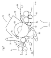
Figur 1 zeigt in rein schematischer Darstellung eine Trockenpartie 10 einer Maschine zur Herstellung einer Materialbahn 12, bei der es sich insbesondere um eine Papier- oder Kartonbahn handeln kann.FIG. 1 shows in a purely schematic representation a
Zwischen dem letzten Preßnip 14 einer Pressenpartie 16 und einer darauffolgenden Impingement- oder Prallströmungs-Trocknungseinheit 18 ist eine größere Pick-up-Saugwalze 20 vorgesehen, die die Materialbahn 12 von einem durch den letzten Preßnip 14 geführten Preßfilz 22 unmittelbar an die Impingement-Trocknungseinheit 18 übergibt.Between the last press nip 14 of a
Der Außendurchmesser der größeren Pick-up-Saugwalze 20 kann beispielsweise in einem Bereich von etwa 1,2 bis etwa 2,5 m liegen.For example, the outer diameter of the larger pick-up
Im vorliegenden Fall ist die Pick-up-Saugwalze 20 von einem Sieb 24 umschlungen.In the present case, the pick-up
Die Impingement-Trocknungseinheit 18 umfaßt eine größere Stützwalze 26 mit zugeordnetem Impingement- oder Prallströmungstrocker, der im vorliegenden Fall eine einteilige Impingementhaube 28 umfaßt. Die Materialbahn 12 wird durch die Pick-up-Saugwalze 20 auf die Stützwalze 26 dieser Impingement-Trocknungseinheit 18 übergeben.The
Die Stützwalze 26 kann insbesondere einen Außendurchmesser im Bereich von beispielsweise etwa 2,5 bis 8 m und vorzugsweise im Bereich von etwa 3 bis etwa 5 m besitzen.The back-
Im vorliegenden Fall ist die Stützwalze 26 von einem Sieb 30 umgeben und durch eine Saugwalze gebildet, der hier ein äußerer Saugkasten 32 zugeordnet ist.In the present case, the
Wie anhand der Figur 1 zu erkennen ist, ist in der im Anschluß an den letzten Preßnip 14 vorgesehenen Impingement-Trocknungseinheit 18 die Impingementhaube 28 so positioniert und/oder der von dieser überdeckte Umschlingungswinkel α so gewählt, daß ein minimaler Abstand zwischen der zugeordneten größeren Stützwalze 26 und dem letzten Preßnip 14 ermöglicht wird (vgl. auch Figur 2).As can be seen with reference to FIG. 1, in the
Die Übernahme der Materialbahn 12 durch die große Stützwalze 26 wird durch eine in Bahnlaufrichtung L im Abstand hinter der Pick-up-Saugwalze 20 angeordnete, innerhalb der Schlaufe des Siebes 24 vorgesehene Umlenkwalze 34 unterstützt. Nachdem diese Umlenkwalze 34 an der Stützwalze 36 anliegt, ist das Sieb 24 und damit die Materialbahn 12 im Bereich zwischen der Pick-up-Saugwalze 20 und der Umlenkwalze 34 an die Stützwalze 26 angelegt.The acquisition of the
Im Anschluß an die Stützwalze 26 wird die Materialbahn 12 im Bereich einer Saugwalze 36 vom Sieb 38 einer ersten Mehrzylindergruppe 40 aus mehreren Trockenzylindern 42 übernommen. Dabei erfolgt die Übernahme so, daß das Papier im Fall eines Abrisses zwischen den Sieben 30 und 38 in den Keller 44 fallen kann.Subsequent to the
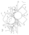
Die Ausführungsform gemäß Figur 2 unterscheidet sich von der zuvor beschriebenen Ausführungsform im wesentlichen dadurch, daß auf die im Anschluß an den letzten Preßnip 14 vorgesehene Impingement-Trocknungseinheit 18 eine weitere Impingement-Trocknungseinheit 18' folgt.The embodiment according to FIG. 2 differs from the previously described embodiment essentially in that the
Auch diese zweite Impingement-Trocknungseinheit 18' umfaßt wieder eine größere Stützwalze 26' und einen dieser zugeordneten, in diesem Fall durch eine zweiteilige Impingementhaube 28' gebildeten Impingement- oder Prallströmungstrockner. Auch in diesem Fall ist die Stützwalze 26' wieder durch eine Saugwalze gebildet, der beispielsweise ein äußerer Saugkasten 32' zugeordnet ist. Im vorliegenden Fall sind die Durchmesser der beiden Stützwalzen 26, 26' zumindest im wesentlichen gleich groß. Die zweite Stützwalze 26 ist vom Sieb 38 der ersten Mehrzylindergruppe 40 umschlungen.This second impingement drying unit 18 'again comprises a larger support roller 26' and an impingement or impingement dryer associated therewith, in this case by a two-part impingement hood 28 '. Also in this case, the support roller 26 'is again formed by a suction roll, for example, an outer Suction box 32 'is associated. In the present case, the diameters of the two
Wie anhand der Figur 2 zu erkennen ist, wird die Materialbahn 12 vom Sieb 30 der ersten Impingement-Trocknungseinheit 18 unmittelbar an die vom Sieb 38 umschlungene große Stützwalze 26' der nachfolgenden zweiten Impingement-Trocknungseinheit 18' übergeben.As can be seen from FIG. 2, the
Die große Stützwalze 26' ist schräg unterhalb der großen Stützwalze 26 angeordnet. Während die Impingementhaube 28 der ersten Impingement-Trocknungseinheit 18 allgemein oberhalb der zugeordneten Stützwalze 26 vorgesehen ist, ist die hier zweiteilige Impingementhaube 28' der darauffolgenden zweiten Impingementhaube 28 allgemein unterhalb der zugeordneten großen Stützwalze 26' angeordnet. Demzufolge werden durch die beiden Impingementhauben 28, 28' unterschiedliche Bahnseiten beaufschlagt.The large back-up roll 26 'is disposed obliquely below the large back-
Im übrigen besitzt die Ausführungsform gemäß Figur 2 zumindest im wesentlichen wieder den gleichen Aufbau wie die der Figur 1. Dabei sind einander entsprechenden Teilen gleiche Bezugszeichen zugeordnet.Moreover, the embodiment according to Figure 2 has at least substantially the same structure as that of Figure 1. In this case, like reference numerals are assigned to corresponding parts.
Claims (26)
- Drying section (10) for a machine for producing a material web (12), in particular a paper or board web, there being provided, between the last press nip (4) of a pressing section (16) and a subsequent impingement drying unit (18) having in particular a relatively large supporting roll (26) and having an associated impingement dryer (28), a pickup suction roll (20), which picks up the material web (12) from a press felt (22) led through the last press nip (14) or from a transfer belt and transfers it to the impingement drying unit (18), characterized in that the external diameter of the pickup suction roll (20) is in the range from about 1.2 to about 2.5 m, a fabric (30) wraps around the supporting roll (26), and the material web (12) is transferred to the fabric (30) of the supporting roll (26) by the pickup suction roll (20).
- Drying section according to Claim 1, characterized in that a fabric (24) wraps around the pickup suction roll (20).
- Drying section according to one of the preceding claims, characterized in that the pickup suction roll (20) is covered with a fabric sleeve.
- Drying section according to one of the preceding claims, characterized in that the pickup suction roll (20) is provided with a suction box located on the inside.
- Drying section according to one of the preceding claims, characterized in that the pickup suction roll (20) is evacuated via its cover by a suction box located on the outside.
- Drying section according to one of the preceding claims, characterized in that the pickup suction roll (20) is provided with a multi-zone suction box.
- Drying section according to one of the preceding claims, characterized in that at least one further impingement drying unit (18') comprising an in particular relatively large supporting roll (26') and an impingement dryer (28') assigned to the latter is provided.
- Drying section according to one of the preceding claims, characterized in that the supporting roll (26, 26') has an external diameter in the range from about 2.5 to about 8 m and preferably in the range from about 3 to 5 m.
- Drying section according to one of the preceding claims, characterized in that the supporting roll (26, 26') is formed by a suction roll.
- Drying section according to one of the preceding claims, characterized in that the supporting roll (26, 26') is formed by a cylinder.
- Drying section according to one of the preceding claims, characterized in that, instead of the supporting roll (26, 26'), a supporting belt led over a plurality of supporting rollers is provided, the supporting rollers being at least partly arranged on a circular arc.
- Drying section according to one of the preceding claims, characterized in that at least one impingement drying unit (18, 18') provided with at least one impingement hood (28, 28') is provided.
- Drying section according to Claim 12,
characterized in that, in the impingement drying unit (18) provided after the last press nip (14), the impingement hood (28) is positioned in such a way and/or the wrap angle (α) covered by the latter is chosen in such a way that a minimum distance between the associated relatively large supporting roll (26) and the last press nip (14) is made possible. - Drying section according to one of the preceding claims, characterized in that at least two successive impingement drying units (28, 28') are provided, in which the material web (12) is transferred directly from the fabric (30) of the one, preceding unit to the large supporting roll (26') of the following, other unit (18').
- Drying section according to one of the preceding claims, characterized in that successive impingement drying units (18, 18') are arranged alternately in such a way that the impingement flows act on different web sides.
- Drying section according to Claim 15,
characterized in that the impingement drying unit (18) provided after the last press nip (14) acts on the top side of the material web (12), and the following impingement drying unit (18') acts on the underside of the material web (12). - Drying section according to Claim 15,
characterized in that the impingement drying unit (18) provided after the last press nip (14) acts on the underside of the material web (12), and the following impingement drying unit (18') acts on the top side of the material web (12). - Drying section (10) for a machine for producing a material web (12), in particular a paper or board web, according to one of the preceding claims, characterized in that it comprises at least one impingement drying unit (18, 18') provided between the last press nip (14) of a pressing section (16) and a first multi-cylinder group (40), and in that the impingement drying unit (18) provided after the last press nip (14) is provided with a one-piece impingement hood (28).
- Drying section according to Claim 18,
characterized in that at least one further impingement drying unit (18') is provided with a multi-part, preferably two-part, impingement hood (28'). - Drying section (10) for a machine for producing a material web (12), in particular a paper or board web, according to one of the preceding claims, characterized in that it comprises at least one impingement drying unit (18, 18') provided between the last press nip (14) of a pressing section (16) and a first multi-cylinder group (40), in order to increase the dryness of the material web (12) to a value in the range from about 55 to about 65%.
- Drying section (10) for a machine for producing a material web (12), in particular a paper or board web, according to one of the preceding claims, characterized in that it comprises at least one impingement drying unit (18, 18') having an upstream or integrated IR unit and preferably provided between the last press nip (14) of a pressing section (16) and a first multi-cylinder group (40).
- Drying section (10) for a machine for producing a material web (12), in particular a paper or board web, according to one of the preceding claims, characterized in that it comprises at least one impingement drying unit (18, 18') which can be operated at a machine speed in the range from about 70 to about 120 m/s, preferably in the range from about 80 to about 100 m/s, and/or at a temperature in the range from about 250 to about 450°C, preferably in the range from about 250 to about 350°C.
- Drying section (10) for a machine for producing a material web (12), in particular a paper or board web, according to one of the preceding claims, characterized in that it comprises at least one impingement drying unit (18, 18'), whose hood (28, 28') is provided with nozzle holes and/or with extraction slots preferably covered against scraps by aperture shields.
- Drying section according to Claim 23,
characterized in that the nozzle holes have a diameter in the range from about 6 to about 10 mm. - Drying section according to Claim 23,
characterized in that the extraction slots covered by aperture shields have an open nozzle area in the range from about 1.5 to about 3.5%. - Drying section (10) for a machine for producing a material web (12), in particular a paper or board web, according to one of the preceding claims,
characterized in that it comprises at least one impingement drying unit (18, 18') and in that a respective break sensor is provided before and/or after a respective impingement drying unit (18, 18') and between successive impingement drying units (18, 18').
Applications Claiming Priority (4)
| Application Number | Priority Date | Filing Date | Title |
|---|---|---|---|
| DE2000125560 DE10025560A1 (en) | 2000-05-24 | 2000-05-24 | The paper/cardboard web drying station has an initial blower dryer with a large pick-up suction roller to transfer the web from the final press nip to a large support roller |
| DE10025560 | 2000-05-24 | ||
| DE20017924U DE20017924U1 (en) | 2000-05-24 | 2000-10-19 | Dryer section |
| DE20017924U | 2000-10-19 |
Publications (3)
| Publication Number | Publication Date |
|---|---|
| EP1158092A2 EP1158092A2 (en) | 2001-11-28 |
| EP1158092A3 EP1158092A3 (en) | 2002-04-24 |
| EP1158092B1 true EP1158092B1 (en) | 2006-09-06 |
Family
ID=26005807
Family Applications (1)
| Application Number | Title | Priority Date | Filing Date |
|---|---|---|---|
| EP01105522A Expired - Lifetime EP1158092B1 (en) | 2000-05-24 | 2001-03-06 | Drying section |
Country Status (4)
| Country | Link |
|---|---|
| US (1) | US6658758B2 (en) |
| EP (1) | EP1158092B1 (en) |
| CA (1) | CA2348371A1 (en) |
| DE (1) | DE50110918D1 (en) |
Cited By (1)
| Publication number | Priority date | Publication date | Assignee | Title |
|---|---|---|---|---|
| DE102007024811A1 (en) | 2007-05-26 | 2008-11-27 | Voith Patent Gmbh | Press unit of machine useful for production and/or handling of paper- or cardboard runs avoids some drawbacks of previous units, e.g. decreased paper or cardboard bending resistance and decreased paper volume due to high press pressure |
Families Citing this family (7)
| Publication number | Priority date | Publication date | Assignee | Title |
|---|---|---|---|---|
| DE102004023321A1 (en) * | 2004-05-07 | 2005-11-24 | Voith Paper Patent Gmbh | Drying section in a machine for producing a fibrous web |
| WO2005111304A1 (en) * | 2004-05-07 | 2005-11-24 | Voith Patent Gmbh | Suction roll in a machine for producing a fibrous material web |
| JP4906724B2 (en) * | 2004-08-16 | 2012-03-28 | ボイス パテント ゲーエムベーハー | Paper machine with a single nip press |
| DE102005017989A1 (en) * | 2005-04-19 | 2006-10-26 | Voith Patent Gmbh | Apparatus for producing a fibrous web |
| DE102005026310A1 (en) * | 2005-06-08 | 2006-12-14 | Voith Patent Gmbh | paper machine |
| DE202005012994U1 (en) * | 2005-08-05 | 2005-11-03 | Voith Paper Patent Gmbh | Drying press for wet carton, paper or tissue paper web has three drying cylinders each succeeded by a stabilising suction box |
| EP2210345A2 (en) * | 2007-10-02 | 2010-07-28 | Imec | An asip architecture for decoding at least two decoding methods |
Family Cites Families (41)
| Publication number | Priority date | Publication date | Assignee | Title |
|---|---|---|---|---|
| US3633282A (en) * | 1969-03-17 | 1972-01-11 | Robert R Candor | Liquid-removing apparatus and method |
| CA1066498A (en) * | 1976-01-21 | 1979-11-20 | Dominion Engineering Works Limited | Paper web streak drying system |
| US4429998A (en) * | 1981-09-17 | 1984-02-07 | Carson/Burger/Weekly, Inc. | Apparatus for the detection of faults in cups, glasses or the like |
| JPS5882107A (en) * | 1981-10-27 | 1983-05-17 | ドウ・ラ・リユ・システムズ・リミテイド | Method and device for detecting state of sheet |
| US4483745A (en) * | 1982-09-29 | 1984-11-20 | Beloit Corporation | Method and apparatus of sheet transfer using a nonporous smooth surfaced belt |
| DE3244045C2 (en) * | 1982-11-27 | 1984-12-20 | M.A.N.- Roland Druckmaschinen AG, 6050 Offenbach | Device to prevent printer damage in the event of paper web breaks |
| DE3544541C1 (en) * | 1985-12-17 | 1987-08-06 | Voith Gmbh J M | Device for transferring a paper or cardboard web from the press section to the dryer section of a paper machine or the like |
| DE3608182A1 (en) * | 1986-03-12 | 1987-10-01 | Roland Man Druckmasch | DEVICE FOR REGULATING THE TENSION OF A PRESSURE CARRIER RAIL WITH AN EMERGENCY STOP DEVICE |
| US4943351A (en) * | 1988-05-23 | 1990-07-24 | Beloit Corporation | Transfer apparatus and method |
| DE3910556C1 (en) * | 1989-04-01 | 1990-10-11 | Man Roland Druckmaschinen Ag, 6050 Offenbach, De | |
| DE4039108C1 (en) * | 1990-12-07 | 1992-04-16 | Man Roland Druckmaschinen Ag, 6050 Offenbach, De | |
| DE4112355A1 (en) * | 1991-04-16 | 1992-10-22 | Escher Wyss Gmbh | PRESS RELEASE OF A PAPER MACHINE |
| FI87669C (en) * | 1992-03-02 | 1993-02-10 | Valmet Paper Machinery Inc | FOERFARANDE OCH TORK VID TORKNING AV PAPPER |
| DE4301750C2 (en) * | 1993-01-23 | 1996-10-10 | Voith Gmbh J M | Method and device for dewatering a web using presses |
| DE4301751C2 (en) * | 1993-01-23 | 1996-10-31 | Voith Gmbh J M | Process for detaching a running fibrous web from two endless sieve belts |
| DE4425662C1 (en) * | 1994-07-20 | 1995-11-16 | Koenig & Bauer Ag | Device for cross cutting a paper web |
| FI102623B (en) * | 1995-10-04 | 1999-01-15 | Valmet Corp | Method and apparatus in a paper machine |
| US6004430A (en) | 1995-10-04 | 1999-12-21 | Ilvespaa; Heikki | Method and device for enhancing the run of a paper web in a paper machine |
| FI110440B (en) * | 1996-04-04 | 2003-01-31 | Metso Paper Inc | Transferring the web from the last press nip in the paper machine to the next drying section |
| US5933981A (en) * | 1996-04-06 | 1999-08-10 | Voith Sulzer Papiermaschinen Gesellschaft Mbh | Device and method for stabilizing a continuous paper web in a paper-making machine in the vicinity of a roll |
| FI107549B (en) * | 1996-06-19 | 2001-08-31 | Metso Paper Inc | Method and apparatus for over-blowing and / or blast-drying paper web or similar web-based material |
| US5968590A (en) * | 1996-09-20 | 1999-10-19 | Valmet Corporation | Method for drying a surface-treated paper web in an after-dryer of a paper machine and after-dryer of a paper machine |
| EP0988418A1 (en) * | 1996-12-23 | 2000-03-29 | Voith Sulzer Papiertechnik Patent GmbH | Wet end, method for the production of a fibrous material web and use of wet end |
| US6003245A (en) * | 1997-04-22 | 1999-12-21 | Valmet Corporation | Method for optimizing of evaporation drying of paper, runnability, and of paper quality as well as dryer section that makes use of the method in a paper machine |
| US6101735A (en) * | 1997-04-22 | 2000-08-15 | Valmet Corporation | Dryer section in a paper machine in which impingement and/or ventilation hoods are used |
| FI103999B (en) * | 1997-04-22 | 1999-10-29 | Valmet Corp | Drying unit and drying unit applying them |
| DE19752562A1 (en) * | 1997-09-29 | 1999-04-01 | Voith Sulzer Papiertech Patent | Paper or cardboard web drying section |
| DE19744341A1 (en) * | 1997-10-07 | 1999-04-15 | Voith Sulzer Papiertech Patent | Paper machine |
| FI114932B (en) * | 1997-12-18 | 2005-01-31 | Metso Paper Inc | Method and apparatus for optimizing drying of a paper web |
| US20020060042A1 (en) * | 1998-03-20 | 2002-05-23 | Ingvar Klerelid | Paper machine for and method of manufacturing soft paper |
| DE19815994A1 (en) * | 1998-04-09 | 1999-10-14 | Voith Sulzer Papiertech Patent | Handover of a fibrous web |
| FI104100B (en) | 1998-06-10 | 1999-11-15 | Valmet Corp | Integrated paper machine |
| FI104001B1 (en) | 1998-06-26 | 1999-10-29 | Valmet Corp | drying Lot |
| WO2000008252A2 (en) | 1998-08-04 | 2000-02-17 | Valmet Corporation | Method and arrangement for handling paper or cardboard webs |
| US6287426B1 (en) * | 1998-09-09 | 2001-09-11 | Valmet-Karlstad Ab | Paper machine for manufacturing structured soft paper |
| DE19935138A1 (en) * | 1998-09-11 | 2000-05-04 | Voith Sulzer Papiertech Patent | Fiber web drying section with a deflection flow dryer, with good drying rate, shortest web drying path and trouble-free web movement through the drying stage |
| DE19841768A1 (en) * | 1998-09-11 | 2000-03-16 | Voith Sulzer Papiertech Patent | Dryer section |
| DE19844927A1 (en) * | 1998-09-30 | 2000-04-06 | Voith Sulzer Papiertech Patent | Measuring system |
| EP1072722B1 (en) * | 1999-07-27 | 2004-12-01 | Voith Paper Patent GmbH | Dryer section |
| DE19959669A1 (en) * | 1999-12-10 | 2001-06-13 | Voith Paper Patent Gmbh | Drying section for e.g. paper web has transfer point where components are slightly spaced apart and run at differing speeds |
| ATE332408T1 (en) * | 2000-03-13 | 2006-07-15 | Voith Paper Patent Gmbh | PRESS ARRANGEMENT |
-
2001
- 2001-03-06 EP EP01105522A patent/EP1158092B1/en not_active Expired - Lifetime
- 2001-03-06 DE DE50110918T patent/DE50110918D1/en not_active Expired - Lifetime
- 2001-05-10 US US09/852,021 patent/US6658758B2/en not_active Expired - Fee Related
- 2001-05-22 CA CA002348371A patent/CA2348371A1/en not_active Abandoned
Cited By (1)
| Publication number | Priority date | Publication date | Assignee | Title |
|---|---|---|---|---|
| DE102007024811A1 (en) | 2007-05-26 | 2008-11-27 | Voith Patent Gmbh | Press unit of machine useful for production and/or handling of paper- or cardboard runs avoids some drawbacks of previous units, e.g. decreased paper or cardboard bending resistance and decreased paper volume due to high press pressure |
Also Published As
| Publication number | Publication date |
|---|---|
| EP1158092A3 (en) | 2002-04-24 |
| US6658758B2 (en) | 2003-12-09 |
| US20010045023A1 (en) | 2001-11-29 |
| EP1158092A2 (en) | 2001-11-28 |
| CA2348371A1 (en) | 2001-11-24 |
| DE50110918D1 (en) | 2006-10-19 |
Similar Documents
| Publication | Publication Date | Title |
|---|---|---|
| EP0509199B2 (en) | Press section for a papermachine | |
| EP0989232A2 (en) | Drying section | |
| DE102020111746A1 (en) | MACHINE FOR THE MANUFACTURE OR TREATMENT OF A FIBER WEB | |
| EP1158092B1 (en) | Drying section | |
| EP1072722B1 (en) | Dryer section | |
| DE202005012994U1 (en) | Drying press for wet carton, paper or tissue paper web has three drying cylinders each succeeded by a stabilising suction box | |
| DE10159115A1 (en) | press section | |
| EP1156155B1 (en) | Dryer section of a machine for manufacturing a paper or board web | |
| EP1739228B1 (en) | Machine for manufacturing a fibrous web | |
| DE102006040508A1 (en) | Paper mill drying station for wet web of paper, carton or tissue paper. Has hot air or steam impingement section and drying belt | |
| EP1186702B2 (en) | Process for controlling a paperbreak and machine for making a web material | |
| EP2391769B1 (en) | Device for producing a material web | |
| DE19935138A1 (en) | Fiber web drying section with a deflection flow dryer, with good drying rate, shortest web drying path and trouble-free web movement through the drying stage | |
| DE19934777A1 (en) | Dryer section producing or finishing paper, card or tissue web includes detachment region without support, which is provided further away by drying sieve | |
| DE10137095A1 (en) | Machine for the production of a fibrous web | |
| DE10259379A1 (en) | Drying section of a paper or board machine | |
| EP1116823B1 (en) | Dryer section | |
| DE10051649A1 (en) | Paper web fed from first press to a second press with an endless belt passing through a higher roller at the same height as second press | |
| DE10025560A1 (en) | The paper/cardboard web drying station has an initial blower dryer with a large pick-up suction roller to transfer the web from the final press nip to a large support roller | |
| EP2003243A1 (en) | Dryer section | |
| EP1731665A1 (en) | Impingement drying arrangement | |
| DE102005009858A1 (en) | paper machine | |
| DE19724219A1 (en) | Paper=making press section for water extraction from wet web | |
| DE202005020882U1 (en) | Dewatering and drying station for paper mill, e.g. for carton, paper or tissue paper has nip gap formed by drying cylinder and smoothing drum | |
| EP4234808A1 (en) | Method and paper machine for producing a bag-type kraft paper web with improved compression during further transport |
Legal Events
| Date | Code | Title | Description |
|---|---|---|---|
| PUAI | Public reference made under article 153(3) epc to a published international application that has entered the european phase |
Free format text: ORIGINAL CODE: 0009012 |
|
| AK | Designated contracting states |
Kind code of ref document: A2 Designated state(s): DE FI SE Kind code of ref document: A2 Designated state(s): AT BE CH CY DE DK ES FI FR GB GR IE IT LI LU MC NL PT SE TR |
|
| AX | Request for extension of the european patent |
Free format text: AL;LT;LV;MK;RO;SI |
|
| PUAL | Search report despatched |
Free format text: ORIGINAL CODE: 0009013 |
|
| RIC1 | Information provided on ipc code assigned before grant |
Free format text: 7D 21F 5/04 A, 7D 21F 5/18 B, 7D 21F 5/00 B |
|
| AK | Designated contracting states |
Kind code of ref document: A3 Designated state(s): AT BE CH CY DE DK ES FI FR GB GR IE IT LI LU MC NL PT SE TR |
|
| AX | Request for extension of the european patent |
Free format text: AL;LT;LV;MK;RO;SI |
|
| 17P | Request for examination filed |
Effective date: 20021024 |
|
| AKX | Designation fees paid |
Free format text: DE FI SE |
|
| GRAP | Despatch of communication of intention to grant a patent |
Free format text: ORIGINAL CODE: EPIDOSNIGR1 |
|
| GRAS | Grant fee paid |
Free format text: ORIGINAL CODE: EPIDOSNIGR3 |
|
| GRAA | (expected) grant |
Free format text: ORIGINAL CODE: 0009210 |
|
| AK | Designated contracting states |
Kind code of ref document: B1 Designated state(s): DE FI SE |
|
| RAP2 | Party data changed (patent owner data changed or rights of a patent transferred) |
Owner name: VOITH PATENT GMBH |
|
| REF | Corresponds to: |
Ref document number: 50110918 Country of ref document: DE Date of ref document: 20061019 Kind code of ref document: P |
|
| REG | Reference to a national code |
Ref country code: SE Ref legal event code: TRGR |
|
| PLBE | No opposition filed within time limit |
Free format text: ORIGINAL CODE: 0009261 |
|
| STAA | Information on the status of an ep patent application or granted ep patent |
Free format text: STATUS: NO OPPOSITION FILED WITHIN TIME LIMIT |
|
| 26N | No opposition filed |
Effective date: 20070607 |
|
| PGFP | Annual fee paid to national office [announced via postgrant information from national office to epo] |
Ref country code: FI Payment date: 20100312 Year of fee payment: 10 |
|
| PGFP | Annual fee paid to national office [announced via postgrant information from national office to epo] |
Ref country code: DE Payment date: 20100324 Year of fee payment: 10 |
|
| PGFP | Annual fee paid to national office [announced via postgrant information from national office to epo] |
Ref country code: SE Payment date: 20100312 Year of fee payment: 10 |
|
| REG | Reference to a national code |
Ref country code: SE Ref legal event code: EUG |
|
| PG25 | Lapsed in a contracting state [announced via postgrant information from national office to epo] |
Ref country code: FI Free format text: LAPSE BECAUSE OF NON-PAYMENT OF DUE FEES Effective date: 20110306 |
|
| PG25 | Lapsed in a contracting state [announced via postgrant information from national office to epo] |
Ref country code: DE Free format text: LAPSE BECAUSE OF NON-PAYMENT OF DUE FEES Effective date: 20111001 |
|
| REG | Reference to a national code |
Ref country code: DE Ref legal event code: R119 Ref document number: 50110918 Country of ref document: DE Effective date: 20111001 |
|
| PG25 | Lapsed in a contracting state [announced via postgrant information from national office to epo] |
Ref country code: SE Free format text: LAPSE BECAUSE OF NON-PAYMENT OF DUE FEES Effective date: 20110307 |