EP0988944A2 - Locher - Google Patents
Locher Download PDFInfo
- Publication number
- EP0988944A2 EP0988944A2 EP99118858A EP99118858A EP0988944A2 EP 0988944 A2 EP0988944 A2 EP 0988944A2 EP 99118858 A EP99118858 A EP 99118858A EP 99118858 A EP99118858 A EP 99118858A EP 0988944 A2 EP0988944 A2 EP 0988944A2
- Authority
- EP
- European Patent Office
- Prior art keywords
- lever arm
- base plate
- plug
- teeth
- foils
- Prior art date
- Legal status (The legal status is an assumption and is not a legal conclusion. Google has not performed a legal analysis and makes no representation as to the accuracy of the status listed.)
- Withdrawn
Links
Images

Classifications
-
- B—PERFORMING OPERATIONS; TRANSPORTING
- B26—HAND CUTTING TOOLS; CUTTING; SEVERING
- B26F—PERFORATING; PUNCHING; CUTTING-OUT; STAMPING-OUT; SEVERING BY MEANS OTHER THAN CUTTING
- B26F1/00—Perforating; Punching; Cutting-out; Stamping-out; Apparatus therefor
- B26F1/32—Hand-held perforating or punching apparatus, e.g. awls
- B26F1/36—Punching or perforating pliers
Definitions
- the invention relates to a manageable punch for Foils, especially of paper, with a base body, one attached via a swivel joint Lever arm, a bottom plate and one above or slide-in compartment arranged directly on the base plate for foils, the two of them spaced punch pins are associated with communicate with the lever arm and when depressed perforate the foils of the lever arm, whereby Bottom plate and / or lever arm essentially determine a level and with a plug-on body are provided.
- Punchers are common and used known. For perforating the foils, especially paper, in the slot brought and the punch pins by pressing on the Lever arm pressed down through the foils, in which perforations remain.
- the slides can now in a ring binder, flat file or the like to be filed.
- the external appearance of the well-known punch is mostly simple, sober and little appealing; the differences in punches are similar Structure are usually limited to the color scheme.
- the base body or, more precisely, the base plate, a stop rail for the side edge of the film or a collecting container for the punched out pieces of paper attached.
- These plug-on bodies are also usually kept sober and are hardly used for used for design purposes.
- the invention has the object propose how to procure a punch must be in spite of largely the same design of the main body, which is a mass production allows different variants of plug-on bodies to largely change the external appearance can be attached.
- the plug-on body is essentially plate-shaped is formed and so on the joint technological face of the lever arm or the base plate is arranged to be essentially in the level of the lever arm or the base plate aligned and the face to which it is attached and part of the surface of the lever arm or the base plate.
- plug-on body Due to the plate-like shape of the plug-on body as well as its orientation in the plane of the lever or the base plate is integrated of the plug body in the outer design of the Lochers.
- a plug-on body becomes plate-shaped designated who defines a level and its Expansion perpendicular to this plane is much less is as in the tangential directions.
- basic shapes can also be molded on or be appropriate that protrude from the plane. Since he is on the technological of the joint Front end is arranged, the plug-on body extends the effective lever length when attached to the lever arm or increased when attached to the base plate the stability when the lever arm is pressed down.
- plug-on body engages around the end face which it is attached to and part of the surface the lever arm or the base plate.
- a side effect is the surface of the lever arm or the base plate at least partially covered, the external appearance is also in these flat areas through the plug-on body certainly.
- a preferred embodiment of the plug-on body is that of an upper or lower jaw.
- the shape of the lower jaw preferred, whose teeth on the lever arm to assign.
- the lever arm when attached to the lever arm aimed at the shape of the upper jaw, whose To point teeth to the base plate.
- training is particularly preferred of the entire hole as a set of teeth that are pressed down of the lever arm at least partially closes.
- the bottom plate alone or with it on attached plug-on body forms the lower jaw, while the lever arm alone or together with an attached body forms the upper jaw.
- the teeth are on the or in the vicinity of the end faces in such a way that the rows of teeth of the upper and lower jaw to point to each other. This results in pressing down the lever arm for perforating the foils the impression of a bit that is at least partially closes.
- the plug body in the longitudinal direction of the lever arm running end faces of the base plate or the lever arm with a component vertically to the longitudinal direction of the swivel joint at least partially encompasses the external appearance of the punch also in side view through the plug-on body certainly.
- a fixing element can be used for fixation be used, the lever arm or the base plate reaches through.
- the following are particularly suitable Screws or bolts.
- Another object of the invention is a punch, whose external appearance are changed can.
- This property is achieved by the Detachable body detachable with the lever arm or the base plate connected is.
- By separating the plug-on body and bringing up another in the way of the exchange is the change of the external appearance possible.
- Fancy designs like that of a bit, if they can be their amusing Have lost effect, or in situations in which such an extraordinary appearance is not desirable to be replaced by others become.
- the inhibition, getting a punch with enormous up to provocative appearance decreases significantly, which is the sale of the invention Punch simplified.
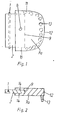
- FIG. 1 shows a punch according to the invention in At sight.
- a is shown in FIG Cross section through lever arm (2) and plug-on body (7a) of the same punch.
- the one Swivel joint (1) attached lever arm (2) is with a plug-on body (7a), which the lever arm (2) on a section distant from the swivel joint (1) encloses.
- a fastening element (8) attached, the lever arm (2) reaches through.
- the push-on body (7a) runs in the plane defined by the lever arm (2) and has the shape of a maxillary dentition, the Teeth (13) near the in the longitudinal direction of the Lever arm extending (11) and that of the swivel joint (1) facing end faces (12) from the common Stand out.
- Figure 3 shows a punch according to the invention in side view, partially cut open, for the foil (6) to be punched on the side of the Swivel joint (1) placed in the slot (4) become.
- Both in the extension of the base plate (3) and the lever arm (2) is in each case a slip body (7a or 7b) attached, the Has the shape of a lower or lower jaw.
- the Hole punch shown partially cut open in the area of the slot (4) is the Hole punch shown partially cut open, so there lever arm (2) and base plate (3), otherwise almost completely from the respective plug-on body (7a and 7b) are covered become.
- the connection is via a swivel joint (1) between lever arm (2) and base plate (3) and when the lever arm (2) is pressed down punch pins (5) are pressed through foils, the thereby experiencing a perforation.
- the movement the punch gives the impression of a bit, that closes during the perforation process and subsequently opens again.
- FIG. 4 shows a shape which is similar Hole puncher, also partially cut open on the side Presentation.
- the main difference too that shown in Figure 3 is that the films (6) on the side facing away from the swivel joint (1) be introduced.
Landscapes
- Life Sciences & Earth Sciences (AREA)
- Forests & Forestry (AREA)
- Engineering & Computer Science (AREA)
- Mechanical Engineering (AREA)
- Perforating, Stamping-Out Or Severing By Means Other Than Cutting (AREA)
- Crystals, And After-Treatments Of Crystals (AREA)
Abstract
Description
- Figur 1 und Figur 2
- eine Verbindung zwischen Hebelarm und Aufsteckkörper
- Figur 3
- einen erfindungsgemäßen Locher, in den zu lochende Folien von der Seite des Schwenkgelenks eingeführt werden und
- Figur 4
- einen erfindungsgemäßen Locher, in den zu perforierende Folien auf der vom Schwenkgelenk abgewandten Seite eingeführt werden.
Claims (7)
- Handhabarer Locher für Folien, insbesondere aus Papier, mit einem Grundkörper, der einen über ein Schwenkgelenk angebrachten Hebelarm, eine Bodenplatte und ein oberhalb oder direkt auf der Bodenplatte angeordnetes Einschubfach für Folien aufweist, dem zwei voneinander beabstandete Stanzstifte zugeordnet sind, die mit dem Hebelarm in Verbindung stehen und bei Herabdrücken des Hebelarmes die Folien perforieren, wobei Bodenplatte und/oder Hebelarm im wesentlichen eine Ebene bestimmen und mit einem Aufsteckkörper versehen sind, dadurch gekennzeichnet, daß der Aufsteckkörper (7a bzw. 7b)im wesentlichen plattenförmig ausgebildet ist undderart an der vom Gelenk wegweisenden Stirnseite (9) des Hebelarmes (2) bzw. der Bodenplatte (3) angeordnet ist, daß erim wesentlichen in die Ebene des Hebelarmes (2) bzw. der Bodenplatte (3) ausgerichtet ist, sowiedie Stirnseite (9), an der er angebracht ist und einen Teil der Oberfläche (14) des Hebelarms (2) bzw. der Bodenplatte (3) umgreift.
- Locher nach Anspruch 1, dadurch gekennzeichnet, daß der mit der Bodenplatte (3) verbundene Aufsteckkörper (7b) die Gestalt eines Gebißunterkiefers aufweist, dessen Zähne (13) auf den Hebelarm (2) zu weisen und/oder der mit dem Hebelarm (2) verbundene Aufsteckkörper (7a) die Gestalt eines Gebißoberkiefers aufweist, dessen Zähne (13) auf die Bodenplatte (3) zu weisen, wobei die Zähne (13) auf oder nahe an der in Längsrichtung des Hebelarmes (2) verlaufenden (11) oder vom Schwenkgelenk (1) wegweisenden Stirnseite (12) des Aufsteckkörpers (7a bzw. 7b) angeordnet sind.
- Locher nach Anspruch 2, dadurch gekennzeichnet, daß Bodenplatte (3) und Hebelarm (2) mit dem/den daran angebracht(en) Aufsteckkörper(n) (7a bzw. 7b) ein Gebiß mit Unter- und Oberkiefer bilden, dessen Zähne (13) auf oder nahe an den Stirnseiten (9, 10, 11, 12) derart angeordnet sind, daß die Zahnreihen von Unter- und Oberkiefer aufeinander zuweisen.
- Locher nach einem der vorhergehenden Ansprüche, dadurch gekennzeichnet, daß der Aufsteckkörper (7a, 7b) die in Längsrichtung des Hebelarmes (2) verlaufenden Stirnseiten (10) der Bodenplatte (3) bzw. des Hebelarmes (2) mit einer Komponente senkrecht zur Längsrichtung des Schwenkgelenkes zumindest teilweise umgreift.
- Locher nach einem der vorhergehenden Ansprüche, dadurch gekennzeichnet, daß der Aufsteckkörper (7a, 7b) eine Markierung des Mittelpunktes zwischen den Stanzstiften (5) und/oder eine Anschlagsschiene für den seitlichen Folienrand aufweist.
- Locher nach einem der vorhergehenden Ansprüche, dadurch gekennzeichnet, daß der Aufsteckkörper (7a, 7b) durch mindestens ein den Hebelarm (2) bzw. die Bodenplatte (3) durchgreifendes Befestigungselement (8) fixiert ist.
- Locher nach einem der vorhergehenden Ansprüche, dadurch gekennzeichnet, daß der Aufsteckkörper (7a, 7b) mit dem Hebelarm (2) und/oder mit der Bodenplatte (3) lösbar verbunden ist.
Applications Claiming Priority (2)
| Application Number | Priority Date | Filing Date | Title |
|---|---|---|---|
| DE29817330U | 1998-09-26 | ||
| DE29817330U DE29817330U1 (de) | 1998-09-26 | 1998-09-26 | Locher |
Publications (2)
| Publication Number | Publication Date |
|---|---|
| EP0988944A2 true EP0988944A2 (de) | 2000-03-29 |
| EP0988944A3 EP0988944A3 (de) | 2002-06-26 |
Family
ID=8063211
Family Applications (1)
| Application Number | Title | Priority Date | Filing Date |
|---|---|---|---|
| EP99118858A Withdrawn EP0988944A3 (de) | 1998-09-26 | 1999-09-24 | Locher |
Country Status (2)
| Country | Link |
|---|---|
| EP (1) | EP0988944A3 (de) |
| DE (1) | DE29817330U1 (de) |
Cited By (1)
| Publication number | Priority date | Publication date | Assignee | Title |
|---|---|---|---|---|
| CN112277048A (zh) * | 2020-10-10 | 2021-01-29 | 深圳云甲科技有限公司 | 一种防尘义齿加工机 |
Family Cites Families (3)
| Publication number | Priority date | Publication date | Assignee | Title |
|---|---|---|---|---|
| DE705175C (de) * | 1938-02-27 | 1941-04-19 | Hugo Hahn | Bekleidung fuer den Fuss oder die Grundplatte von Buerogeraeten |
| US4594927A (en) * | 1982-09-27 | 1986-06-17 | Carl Manufacturing Co., Ltd. | Punch having improved cutter attachment means |
| DE8901642U1 (de) * | 1989-02-14 | 1989-03-23 | Elba-Ordner-Fabrik Kraut & Meienborn Gmbh & Co, 5600 Wuppertal | Locher für Schriftgut |
-
1998
- 1998-09-26 DE DE29817330U patent/DE29817330U1/de not_active Expired - Lifetime
-
1999
- 1999-09-24 EP EP99118858A patent/EP0988944A3/de not_active Withdrawn
Cited By (1)
| Publication number | Priority date | Publication date | Assignee | Title |
|---|---|---|---|---|
| CN112277048A (zh) * | 2020-10-10 | 2021-01-29 | 深圳云甲科技有限公司 | 一种防尘义齿加工机 |
Also Published As
| Publication number | Publication date |
|---|---|
| EP0988944A3 (de) | 2002-06-26 |
| DE29817330U1 (de) | 1999-02-18 |
Similar Documents
| Publication | Publication Date | Title |
|---|---|---|
| DE69720660T2 (de) | Gegenstand bestehend aus einem Formteil und einem eingelegten dekorativen Element und Verfahren zu seiner Herstellung | |
| DE102004036171A1 (de) | Verfahren und Vorrichtung zur Herstellung eines Dekor-Zierteils mit freigestelltem Symbol | |
| DE60320261T2 (de) | Matrize einer stanzpresse | |
| DE102009034437A1 (de) | Vorrichtung und Verfahren zur Ausbildung einer Kontur in einem Kartenkörper für einen tragbaren Datenträger, insbesondere für eine Chipkarte | |
| EP0988944A2 (de) | Locher | |
| DE3101995A1 (de) | Verfahren zur herstellung von elektrischen kontakstuecken | |
| DE3100415A1 (de) | Verfahren zum ausbilden von perforationslinien auf einem papier sowie diesbezuegliches spielzeug zum ausstanzen der perforationslinien | |
| DE3016168C2 (de) | Gesamtverbundschneid- und Biegewerkzeug | |
| DE2636767A1 (de) | Einschlaggehaeuse fuer moebelscharniere | |
| DE102006027009B4 (de) | Papierlocher | |
| DE102015115170A1 (de) | Verfahren und Vorrichtung zum einstufigen Beschneiden großer Schnittlängen | |
| DE1909003A1 (de) | Locher fuer Schriftgut | |
| AT61479B (de) | Verfahren zur Herstellung von eingelegten Arbeiten. | |
| DE29708638U1 (de) | Backgerät zum Backen von Backwaren | |
| DE102009047208A1 (de) | Stanzwerkzeug und Verfahren zum Herstellen eines Befestigungsteils eines Wischarms | |
| DE469323C (de) | Verfahren zur Herstellung von Reliefplatten, insbesondere von Schildern mit erhabenen oder vertieften Buchstaben und Zahlen | |
| DE1945011A1 (de) | Stufenfoermig ausgebildetes Ziehwerkzeug | |
| DE8405035U1 (de) | Vorrichtung zum formen, insbesondere thermoformen von duennwandigen behaelterdeckeln | |
| DE3734945C2 (de) | ||
| DE29921083U1 (de) | Vorrichtung zum Präsentieren von Plakaten | |
| DE729876C (de) | Verfahren zur Herstellung eines Bremsklotzschuhes durch Schmieden im Gesenk | |
| DE321341C (de) | Verfahren und Vorrichtung zur Herstellung von Flittern | |
| DE745506C (de) | Formwerkzeug zum Herstellen eines aus einem Kunststoff gefertigten Dachteiles an einem Wagenkasten fuer Kraftfahrzeuge | |
| AT150320B (de) | Vorrichtung zur Herstellung von Falzen in Papier, Karton u. dgl. | |
| DE865635C (de) | Verfahren und Vorrichtung zur Herstellung dreidimensional plastischer kuenstlicher Zaehne |
Legal Events
| Date | Code | Title | Description |
|---|---|---|---|
| PUAI | Public reference made under article 153(3) epc to a published international application that has entered the european phase |
Free format text: ORIGINAL CODE: 0009012 |
|
| AK | Designated contracting states |
Kind code of ref document: A2 Designated state(s): AT BE CH CY DE DK ES FI FR GB GR IE IT LI LU MC NL PT SE |
|
| AX | Request for extension of the european patent |
Free format text: AL;LT;LV;MK;RO;SI |
|
| PUAL | Search report despatched |
Free format text: ORIGINAL CODE: 0009013 |
|
| AK | Designated contracting states |
Kind code of ref document: A3 Designated state(s): AT BE CH CY DE DK ES FI FR GB GR IE IT LI LU MC NL PT SE |
|
| AX | Request for extension of the european patent |
Free format text: AL;LT;LV;MK;RO;SI |
|
| 17P | Request for examination filed |
Effective date: 20021218 |
|
| AKX | Designation fees paid |
Designated state(s): AT BE CH CY DE DK ES FI FR GB GR IE IT LI LU MC NL PT SE |
|
| 17Q | First examination report despatched |
Effective date: 20030728 |
|
| STAA | Information on the status of an ep patent application or granted ep patent |
Free format text: STATUS: THE APPLICATION IS DEEMED TO BE WITHDRAWN |
|
| 18D | Application deemed to be withdrawn |
Effective date: 20040210 |