EP0988944A2 - Punch - Google Patents
Punch Download PDFInfo
- Publication number
- EP0988944A2 EP0988944A2 EP99118858A EP99118858A EP0988944A2 EP 0988944 A2 EP0988944 A2 EP 0988944A2 EP 99118858 A EP99118858 A EP 99118858A EP 99118858 A EP99118858 A EP 99118858A EP 0988944 A2 EP0988944 A2 EP 0988944A2
- Authority
- EP
- European Patent Office
- Prior art keywords
- lever arm
- base plate
- plug
- teeth
- punch
- Prior art date
- Legal status (The legal status is an assumption and is not a legal conclusion. Google has not performed a legal analysis and makes no representation as to the accuracy of the status listed.)
- Withdrawn
Links
Images

Classifications
-
- B—PERFORMING OPERATIONS; TRANSPORTING
- B26—HAND CUTTING TOOLS; CUTTING; SEVERING
- B26F—PERFORATING; PUNCHING; CUTTING-OUT; STAMPING-OUT; SEVERING BY MEANS OTHER THAN CUTTING
- B26F1/00—Perforating; Punching; Cutting-out; Stamping-out; Apparatus therefor
- B26F1/32—Hand-held perforating or punching apparatus, e.g. awls
- B26F1/36—Punching or perforating pliers
Definitions
- the invention relates to a manageable punch for Foils, especially of paper, with a base body, one attached via a swivel joint Lever arm, a bottom plate and one above or slide-in compartment arranged directly on the base plate for foils, the two of them spaced punch pins are associated with communicate with the lever arm and when depressed perforate the foils of the lever arm, whereby Bottom plate and / or lever arm essentially determine a level and with a plug-on body are provided.
- Punchers are common and used known. For perforating the foils, especially paper, in the slot brought and the punch pins by pressing on the Lever arm pressed down through the foils, in which perforations remain.
- the slides can now in a ring binder, flat file or the like to be filed.
- the external appearance of the well-known punch is mostly simple, sober and little appealing; the differences in punches are similar Structure are usually limited to the color scheme.
- the base body or, more precisely, the base plate, a stop rail for the side edge of the film or a collecting container for the punched out pieces of paper attached.
- These plug-on bodies are also usually kept sober and are hardly used for used for design purposes.
- the invention has the object propose how to procure a punch must be in spite of largely the same design of the main body, which is a mass production allows different variants of plug-on bodies to largely change the external appearance can be attached.
- the plug-on body is essentially plate-shaped is formed and so on the joint technological face of the lever arm or the base plate is arranged to be essentially in the level of the lever arm or the base plate aligned and the face to which it is attached and part of the surface of the lever arm or the base plate.
- plug-on body Due to the plate-like shape of the plug-on body as well as its orientation in the plane of the lever or the base plate is integrated of the plug body in the outer design of the Lochers.
- a plug-on body becomes plate-shaped designated who defines a level and its Expansion perpendicular to this plane is much less is as in the tangential directions.
- basic shapes can also be molded on or be appropriate that protrude from the plane. Since he is on the technological of the joint Front end is arranged, the plug-on body extends the effective lever length when attached to the lever arm or increased when attached to the base plate the stability when the lever arm is pressed down.
- plug-on body engages around the end face which it is attached to and part of the surface the lever arm or the base plate.
- a side effect is the surface of the lever arm or the base plate at least partially covered, the external appearance is also in these flat areas through the plug-on body certainly.
- a preferred embodiment of the plug-on body is that of an upper or lower jaw.
- the shape of the lower jaw preferred, whose teeth on the lever arm to assign.
- the lever arm when attached to the lever arm aimed at the shape of the upper jaw, whose To point teeth to the base plate.
- training is particularly preferred of the entire hole as a set of teeth that are pressed down of the lever arm at least partially closes.
- the bottom plate alone or with it on attached plug-on body forms the lower jaw, while the lever arm alone or together with an attached body forms the upper jaw.
- the teeth are on the or in the vicinity of the end faces in such a way that the rows of teeth of the upper and lower jaw to point to each other. This results in pressing down the lever arm for perforating the foils the impression of a bit that is at least partially closes.
- the plug body in the longitudinal direction of the lever arm running end faces of the base plate or the lever arm with a component vertically to the longitudinal direction of the swivel joint at least partially encompasses the external appearance of the punch also in side view through the plug-on body certainly.
- a fixing element can be used for fixation be used, the lever arm or the base plate reaches through.
- the following are particularly suitable Screws or bolts.
- Another object of the invention is a punch, whose external appearance are changed can.
- This property is achieved by the Detachable body detachable with the lever arm or the base plate connected is.
- By separating the plug-on body and bringing up another in the way of the exchange is the change of the external appearance possible.
- Fancy designs like that of a bit, if they can be their amusing Have lost effect, or in situations in which such an extraordinary appearance is not desirable to be replaced by others become.
- the inhibition, getting a punch with enormous up to provocative appearance decreases significantly, which is the sale of the invention Punch simplified.
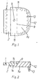
- FIG. 1 shows a punch according to the invention in At sight.
- a is shown in FIG Cross section through lever arm (2) and plug-on body (7a) of the same punch.
- the one Swivel joint (1) attached lever arm (2) is with a plug-on body (7a), which the lever arm (2) on a section distant from the swivel joint (1) encloses.
- a fastening element (8) attached, the lever arm (2) reaches through.
- the push-on body (7a) runs in the plane defined by the lever arm (2) and has the shape of a maxillary dentition, the Teeth (13) near the in the longitudinal direction of the Lever arm extending (11) and that of the swivel joint (1) facing end faces (12) from the common Stand out.
- Figure 3 shows a punch according to the invention in side view, partially cut open, for the foil (6) to be punched on the side of the Swivel joint (1) placed in the slot (4) become.
- Both in the extension of the base plate (3) and the lever arm (2) is in each case a slip body (7a or 7b) attached, the Has the shape of a lower or lower jaw.
- the Hole punch shown partially cut open in the area of the slot (4) is the Hole punch shown partially cut open, so there lever arm (2) and base plate (3), otherwise almost completely from the respective plug-on body (7a and 7b) are covered become.
- the connection is via a swivel joint (1) between lever arm (2) and base plate (3) and when the lever arm (2) is pressed down punch pins (5) are pressed through foils, the thereby experiencing a perforation.
- the movement the punch gives the impression of a bit, that closes during the perforation process and subsequently opens again.
- FIG. 4 shows a shape which is similar Hole puncher, also partially cut open on the side Presentation.
- the main difference too that shown in Figure 3 is that the films (6) on the side facing away from the swivel joint (1) be introduced.
Abstract
Description
Die Erfindung betrifft einen handhabaren Locher für Folien, insbesondere aus Papier, mit einem Grundkörper, der einen über ein Schwenkgelenk angebrachten Hebelarm, eine Bodenplatte und ein oberhalb oder direkt auf der Bodenplatte angeordnetes Einschubfach für Folien aufweist, dem zwei voneinander beabstandete Stanzstifte zugeordnet sind, die mit dem Hebelarm in Verbindung stehen und bei Herabdrücken des Hebelarmes die Folien perforieren, wobei Bodenplatte und/oder Hebelarm im wesentlichen eine Ebene bestimmen und mit einem Aufsteckkörper versehen sind.The invention relates to a manageable punch for Foils, especially of paper, with a base body, one attached via a swivel joint Lever arm, a bottom plate and one above or slide-in compartment arranged directly on the base plate for foils, the two of them spaced punch pins are associated with communicate with the lever arm and when depressed perforate the foils of the lever arm, whereby Bottom plate and / or lever arm essentially determine a level and with a plug-on body are provided.
Locher sind allgemein geläufig und in ihrer Verwendungsweise bekannt. Zum Perforieren werden die Folien, insbesondere aus Papier, in das Einschubfach gebracht und die Stanzstifte durch Druck auf den Hebelarm nach unten durch die Folien hindurch gepreßt, in denen Perforationen verbleiben. Die Folien können nun in einem Ringbuch, Schnellhefter odgl. abgeheftet werden.Punchers are common and used known. For perforating the foils, especially paper, in the slot brought and the punch pins by pressing on the Lever arm pressed down through the foils, in which perforations remain. The slides can now in a ring binder, flat file or the like to be filed.
Das äußere Erscheinungsbild der bekannten Locher ist allerdings zumeist schlicht, nüchtern und wenig ansprechend; die Unterschiede bei Lochern ähnlichen Aufbaus beschränken sich in der Regel auf die Farbgebung. Bei einigen Modellen sind auf den Grundkörper, oder, genauer gesagt die Bodenplatte, eine Anschlagschiene für den seitlichen Folienrand oder ein Auffangbehälter für die ausgestanzten Papierstücke aufgesteckt. Auch diese Aufsteckkörper sind in der Regel nüchtern gehalten und werden kaum für gestalterische Zwecke genutzt.The external appearance of the well-known punch is mostly simple, sober and little appealing; the differences in punches are similar Structure are usually limited to the color scheme. On some models, the base body, or, more precisely, the base plate, a stop rail for the side edge of the film or a collecting container for the punched out pieces of paper attached. These plug-on bodies are also usually kept sober and are hardly used for used for design purposes.
Die Erfindung hat sich demgegenüber die Aufgabe gestellt, vorzuschlagen, wie ein Locher beschaffen sein muß, bei dem trotz weitgehend gleicher Gestaltung des Grundkörpers, die eine Massenproduktion zuläßt, unterschiedliche Varianten von Aufsteckkörpern zur weitgehenden Veränderung des äußeren Erscheinungsbildes angebracht werden können.In contrast, the invention has the object propose how to procure a punch must be in spite of largely the same design of the main body, which is a mass production allows different variants of plug-on bodies to largely change the external appearance can be attached.
Diese Aufgabe wird erfindungsgemäß dadurch gelöst, daß der Aufsteckkörper im wesentlichen plattenförmig ausgebildet ist und derart an der vom Gelenk wegweisenden Stirnseite des Hebelarmes bzw. der Bodenplatte angeordnet ist, daß er im wesentlichen in die Ebene des Hebelarmes bzw. der Bodenplatte ausgerichtet ist, sowie die Stirnseite, an der er angebracht ist und einen Teil der Oberfläche des Hebelarms bzw. der Bodenplatte umgreift.According to the invention, this object is achieved by that the plug-on body is essentially plate-shaped is formed and so on the joint groundbreaking face of the lever arm or the base plate is arranged to be essentially in the level of the lever arm or the base plate aligned and the face to which it is attached and part of the surface of the lever arm or the base plate.
Durch die plattenförmige Gestalt des Aufsteckkörpers sowie seine Ausrichtung in der Ebene des Hebels bzw. der Bodenplatte erfolgt eine Integration des Aufsteckkörpers in die äußere Gestaltung des Lochers. Als plattenförmig wird ein Aufsteckkörper bezeichnet, der eine Ebene definiert und dessen Ausdehnung senkrecht zu dieser Ebene wesentlich geringer ist als in den Tangentialrichtungen. An dieser Grundform können allerdings auch Elemente angeformt oder angebracht sein, die aus der Ebene herausstehen. Da er an der vom Gelenk wegweisenden Stirnseite angeordnet ist, verlängert der Aufsteckkörper bei Anbringung am Hebelarm die wirksame Hebellänge oder erhöht bei Anbringung an der Bodenplatte die Standfestigkeit bei Herabdrücken des Hebelarmes. Damit eine bleibende, starre Verbindung zwischen Aufsteckkörper und Grundkörper gegeben ist, umgreift der Aufsteckkörper die Stirnseite, an der er angebracht ist und einen Teil der Oberfläche des Hebelarms bzw. der Bodenplatte. Als vorteilhafter Nebeneffekt ist dadurch die Oberfläche des Hebelarmes bzw. der Bodenplatte zumindest teilweise abgedeckt, das äußere Erscheinungsbild ist auch in diesen flächigen Bereichen durch den Aufsteckkörper bestimmt.Due to the plate-like shape of the plug-on body as well as its orientation in the plane of the lever or the base plate is integrated of the plug body in the outer design of the Lochers. A plug-on body becomes plate-shaped designated who defines a level and its Expansion perpendicular to this plane is much less is as in the tangential directions. At this However, basic shapes can also be molded on or be appropriate that protrude from the plane. Since he is on the groundbreaking of the joint Front end is arranged, the plug-on body extends the effective lever length when attached to the lever arm or increased when attached to the base plate the stability when the lever arm is pressed down. So that a permanent, rigid connection between plug-in body and base body is, the plug-on body engages around the end face which it is attached to and part of the surface the lever arm or the base plate. As more advantageous A side effect is the surface of the lever arm or the base plate at least partially covered, the external appearance is also in these flat areas through the plug-on body certainly.
Eine bevorzugte Ausbildung des Aufsteckkörpers ist die eines Gebißober- oder Gebißunterkiefers. Bei Anbringung an der Bodenplatte ist die Form des Unterkiefers bevorzugt, dessen Zähne auf den Hebelarm zu weisen. Bei Anbringen am Hebelarm dagegen wird die Gestalt des Oberkiefers angestrebt, dessen Zähne auf die Bodenplatte zu weisen. Unabhängig davon, ob als Ober- oder Unterkiefer gestaltet, sind die Zähne zur besseren Erkennbarkeit auf oder nahe an der vom Schwenkgelenk weg weisenden und der in Längsrichtung des Hebelarmes verlaufenden Stirnseite des Aufsteckkörpers anzuordnen.A preferred embodiment of the plug-on body is that of an upper or lower jaw. At Attachment to the base plate is the shape of the lower jaw preferred, whose teeth on the lever arm to assign. In contrast, when attached to the lever arm aimed at the shape of the upper jaw, whose To point teeth to the base plate. Independently of, whether designed as an upper or lower jaw teeth on or near for better visibility on the one pointing away from the swivel joint and the one in Longitudinal direction of the lever arm end face to arrange the plug-on body.
Besonders bevorzugt allerdings ist die Ausbildung des gesamten Lochers als Gebiß, das sich bei Herabdrücken des Hebelarmes zumindest teilweise schließt. Die Bodenplatte allein oder mit dem daran angebrachten Aufsteckkörper bildet dabei den Gebißunterkiefer, während der Hebelarm allein oder zusammen mit einem daran angebrachten Aufsteckkörper den Oberkiefer bildet. Die Zähne sind dabei an den oder in der Nähe der Stirnseiten derart anzubringen, daß die Zahnreihen von Ober- und Unterkiefer aufeinander zu weisen. Daraus ergibt sich beim Herabdrücken des Hebelarmes zum Perforieren der Folien der Eindruck eines Gebisses, das sich zumindest teilweise schließt.However, training is particularly preferred of the entire hole as a set of teeth that are pressed down of the lever arm at least partially closes. The bottom plate alone or with it on attached plug-on body forms the lower jaw, while the lever arm alone or together with an attached body forms the upper jaw. The teeth are on the or in the vicinity of the end faces in such a way that the rows of teeth of the upper and lower jaw to point to each other. This results in pressing down the lever arm for perforating the foils the impression of a bit that is at least partially closes.
Da der Aufsteckkörper die in Längsrichtung des Hebelarmes verlaufende Stirnseiten der Bodenplatte bzw. des Hebelarmes mit einer Komponente senkrecht zur Längsrichtung des Schwenkgelenks zumindest teilweise umgreift, ist das äußere Erscheinungsbild des Lochers auch in Seitenansicht durch den Aufsteckkörper bestimmt.Since the plug body in the longitudinal direction of the lever arm running end faces of the base plate or the lever arm with a component vertically to the longitudinal direction of the swivel joint at least partially encompasses the external appearance of the punch also in side view through the plug-on body certainly.
Damit die Folien mittig perforiert werden, enthalten Locher häufig eine Markierung des Mittelpunktes zwischen den Stanzstiften oder eine Anschlagschiene, an der der seitliche Folienrand dann, wenn die Folie mittig perforiert wird, anzulegen ist. Derartige Elemente sind relativ nüchtern gestaltet und können damit das durch den Aufsteckkörper erreichte Erscheinungsbild stören. Zur Abhilfe wird vorgeschlagen, diese Elemente am Aufsteckkörper anzubringen, wodurch eine einfache Anpassung an das spezielle Erscheinungsbild möglich ist.So that the films are perforated in the middle Punch often marks the center between the punch pins or a stop rail, at which the side edge of the film if the film is perforated in the middle. Such elements are relatively sober and can thus achieve that through the plug-on body Disturb appearance. To remedy this proposed to attach these elements to the plug body, making an easy adjustment to that special appearance is possible.
Damit die Stabilität der Befestigung des Aufsteckkörpers am Hebelarm bzw. an der Bodenplatte erhöht wird, kann zur Fixierung ein Befestigungselement eingesetzt werden, das den Hebelarm bzw. die Bodenplatte durchgreift. Geeignet hierzu sind insbesondere Schrauben oder Bolzen.So that the stability of the attachment of the plug body raised on the lever arm or on the base plate a fixing element can be used for fixation be used, the lever arm or the base plate reaches through. The following are particularly suitable Screws or bolts.
Ein weiteres Ziel der Erfindung ist ein Locher, dessen äußeres Erscheinungsbild verändert werden kann. Diese Eigenschaft wird erreicht, indem der Aufsteckkörper lösbar mit dem Hebelarm bzw. der Bodenplatte verbunden ist. Durch Trennen des Aufsteckkörpers und Aufbringung eines anderen im Wege des Austausches ist die Änderung des äußeren Erscheinungsbildes möglich. Ausgefallene Designs wie das eines Gebisses, können, wenn sie ihre belustigende Wirkung verloren haben, oder in Situationen, in denen ein derart außergewöhnliches Erscheinungsbild nicht erstrebenswert ist, durch andere ersetzt werden. Die Hemmschwelle, sich einen Locher mit extravagantem bis provokantem Erscheinungsbild zuzulegen, sinkt erheblich, was den Verkauf der erfindungsgemäßen Locher vereinfacht.Another object of the invention is a punch, whose external appearance are changed can. This property is achieved by the Detachable body detachable with the lever arm or the base plate connected is. By separating the plug-on body and bringing up another in the way of the exchange is the change of the external appearance possible. Fancy designs like that of a bit, if they can be their amusing Have lost effect, or in situations in which such an extraordinary appearance is not desirable to be replaced by others become. The inhibition, getting a punch with extravagant up to provocative appearance, decreases significantly, which is the sale of the invention Punch simplified.
Weitere Einzelheiten, Merkmale und Vorteile der Erfindung lassen sich dem nachfolgenden Beschreibungsteil entnehmen, in dem anhand von Zeichnungen Ausführungsbeispiele der Erfindung näher erläutert sind. Dabei zeigen in prinzipienhafter Darstellung
-
Figur 1 undFigur 2 - eine Verbindung zwischen Hebelarm und Aufsteckkörper
-
Figur 3 - einen erfindungsgemäßen Locher, in den zu lochende Folien von der Seite des Schwenkgelenks eingeführt werden und
- Figur 4
- einen erfindungsgemäßen Locher, in den zu perforierende Folien auf der vom Schwenkgelenk abgewandten Seite eingeführt werden.
- Figure 1 and Figure 2
- a connection between lever arm and plug-on body
- Figure 3
- a punch according to the invention, are inserted into the films to be punched from the side of the swivel joint and
- Figure 4
- a hole punch according to the invention, into which films to be perforated are inserted on the side facing away from the swivel joint.
Figur 1 zeigt einen erfindungsgemäßen Locher in Aufsicht. Zur Verdeutlichung ist in Figur 2 ein Querschnitt durch Hebelarm (2) und Aufsteckkörper (7a) desselben Lochers dargestellt. Der über ein Schwenkgelenk (1) angebrachte Hebelarm (2) ist mit einem Aufsteckkörper (7a) versehen, der den Hebelarm (2) auf einem vom Schwenkgelenk (1) fernen Abschnitt umschließt. Dabei wird sowohl die vom Schwenkgelenk (1) wegweisende Stirnseite (9), als auch ein Teil der in Längsrichtung des Hebelarmes (2) verlaufenden Stirnseiten (10) und ein Teil der Oberfläche (14) des Hebelarmes (2) vom Aufsteckkörper (7a) umgriffen. Zur bessern Fixierung des Aufsteckkörpers (7a) am Hebelarm (2) ist ein Befestigungselement (8) angebracht, das den Hebelarm (2) durchgreift. Der Aufsteckkörper (7a) verläuft in der durch den Hebelarm (2) definierten Ebene und weist die Gestalt eines Gebißoberkiefers auf, dessen Zähne (13) in der Nähe der in Längsrichtung des Hebelarmes verlaufenden (11) und der vom Schwenkgelenk (1) weg weisenden Stirnseiten (12) aus der gemeinsamen Ebene herausstehen.Figure 1 shows a punch according to the invention in At sight. For clarification, a is shown in FIG Cross section through lever arm (2) and plug-on body (7a) of the same punch. The one Swivel joint (1) attached lever arm (2) is with a plug-on body (7a), which the lever arm (2) on a section distant from the swivel joint (1) encloses. Both the Swivel joint (1) pioneering face (9), as also part of the longitudinal direction of the lever arm (2) extending end faces (10) and part of the Surface (14) of the lever arm (2) from the plug-on body (7a) encompassed. For better fixation of the plug-on body (7a) on the lever arm (2) is a fastening element (8) attached, the lever arm (2) reaches through. The push-on body (7a) runs in the plane defined by the lever arm (2) and has the shape of a maxillary dentition, the Teeth (13) near the in the longitudinal direction of the Lever arm extending (11) and that of the swivel joint (1) facing end faces (12) from the common Stand out.
Figur 3 zeigt einen erfindungsgemäßen Locher in seitlicher, teilweise aufgeschnittener Darstellung, bei dem zu lochende Folien (6) auf der Seite des Schwenkgelenks (1) in das Einschubfach (4) verbracht werden. Sowohl in Verlängerung der Bodenplatte (3) als auch des Hebelarmes (2) ist jeweils ein Aufsteckkörper (7a bzw. 7b) angebracht, der die Form eines Gebißunter- bzw. Gebißoberkiefers aufweist. Im Bereich des Einschubfaches (4) ist der Locher zum Teil aufgeschnitten dargestellt, sodaß dort Hebelarm (2) und Bodenplatte (3), die ansonsten nahezu vollständig von dem jeweiligen Aufsteckkörper (7a bzw. 7b) bedeckt sind, erkennbar werden. Über ein Schwenkgelenk (1) ist die Verbindung zwischen Hebelarm (2) und Bodenplatte (3) hergestellt und bei Herabdrücken des Hebelarmes (2) werden Stanzstifte (5) durch Folien gepreßt, die hierdurch eine Perforation erfahren. Die Bewegung des Lochers erweckt den Eindruck eines Gebisses, das sich beim Perforationsvorgang schließt und nachfolgend wieder öffnet.Figure 3 shows a punch according to the invention in side view, partially cut open, for the foil (6) to be punched on the side of the Swivel joint (1) placed in the slot (4) become. Both in the extension of the base plate (3) and the lever arm (2) is in each case a slip body (7a or 7b) attached, the Has the shape of a lower or lower jaw. In the area of the slot (4) is the Hole punch shown partially cut open, so there lever arm (2) and base plate (3), otherwise almost completely from the respective plug-on body (7a and 7b) are covered become. The connection is via a swivel joint (1) between lever arm (2) and base plate (3) and when the lever arm (2) is pressed down punch pins (5) are pressed through foils, the thereby experiencing a perforation. The movement the punch gives the impression of a bit, that closes during the perforation process and subsequently opens again.
Figur 4 zeigt einen von der Formgebung her ähnlichen Locher, ebenfalls in seitlicher teilweise aufgeschnittener Darstellung. Der Hauptunterschied zu den in Figur 3 dargestellten ist, daß die Folien (6) auf der vom Schwenkgelenk (1) abgewandten Seite eingeführt werden.FIG. 4 shows a shape which is similar Hole puncher, also partially cut open on the side Presentation. The main difference too that shown in Figure 3 is that the films (6) on the side facing away from the swivel joint (1) be introduced.
Claims (7)
Applications Claiming Priority (2)
| Application Number | Priority Date | Filing Date | Title |
|---|---|---|---|
| DE29817330U DE29817330U1 (en) | 1998-09-26 | 1998-09-26 | Perforator |
| DE29817330U | 1998-09-26 |
Publications (2)
| Publication Number | Publication Date |
|---|---|
| EP0988944A2 true EP0988944A2 (en) | 2000-03-29 |
| EP0988944A3 EP0988944A3 (en) | 2002-06-26 |
Family
ID=8063211
Family Applications (1)
| Application Number | Title | Priority Date | Filing Date |
|---|---|---|---|
| EP99118858A Withdrawn EP0988944A3 (en) | 1998-09-26 | 1999-09-24 | Punch |
Country Status (2)
| Country | Link |
|---|---|
| EP (1) | EP0988944A3 (en) |
| DE (1) | DE29817330U1 (en) |
Cited By (1)
| Publication number | Priority date | Publication date | Assignee | Title |
|---|---|---|---|---|
| CN112277048A (en) * | 2020-10-10 | 2021-01-29 | 深圳云甲科技有限公司 | Dustproof false tooth processing machine |
Citations (3)
| Publication number | Priority date | Publication date | Assignee | Title |
|---|---|---|---|---|
| DE705175C (en) * | 1938-02-27 | 1941-04-19 | Hugo Hahn | Clothing for the foot or the base of office equipment |
| US4594927A (en) * | 1982-09-27 | 1986-06-17 | Carl Manufacturing Co., Ltd. | Punch having improved cutter attachment means |
| DE8901642U1 (en) * | 1989-02-14 | 1989-03-23 | Elba-Ordner-Fabrik Kraut & Meienborn Gmbh & Co, 5600 Wuppertal, De |
-
1998
- 1998-09-26 DE DE29817330U patent/DE29817330U1/en not_active Expired - Lifetime
-
1999
- 1999-09-24 EP EP99118858A patent/EP0988944A3/en not_active Withdrawn
Patent Citations (3)
| Publication number | Priority date | Publication date | Assignee | Title |
|---|---|---|---|---|
| DE705175C (en) * | 1938-02-27 | 1941-04-19 | Hugo Hahn | Clothing for the foot or the base of office equipment |
| US4594927A (en) * | 1982-09-27 | 1986-06-17 | Carl Manufacturing Co., Ltd. | Punch having improved cutter attachment means |
| DE8901642U1 (en) * | 1989-02-14 | 1989-03-23 | Elba-Ordner-Fabrik Kraut & Meienborn Gmbh & Co, 5600 Wuppertal, De |
Cited By (1)
| Publication number | Priority date | Publication date | Assignee | Title |
|---|---|---|---|---|
| CN112277048A (en) * | 2020-10-10 | 2021-01-29 | 深圳云甲科技有限公司 | Dustproof false tooth processing machine |
Also Published As
| Publication number | Publication date |
|---|---|
| EP0988944A3 (en) | 2002-06-26 |
| DE29817330U1 (en) | 1999-02-18 |
Similar Documents
| Publication | Publication Date | Title |
|---|---|---|
| DE102004036171A1 (en) | Method and device for producing a decorative trim part with a freed symbol | |
| DE69720660T2 (en) | Object consisting of a molded part and an inlaid decorative element and process for its production | |
| EP0988944A2 (en) | Punch | |
| DE102006027009B4 (en) | paper punch | |
| DE3100415A1 (en) | METHOD FOR FORMING PERFORATION LINES ON PAPER AND TOOL FOR CUTTING OUT THE PERFORATION LINES | |
| DE3641995C1 (en) | Process for the production of printed circuits | |
| AT61479B (en) | Process for producing inlaid works. | |
| CH691457A5 (en) | Ring notebook with ring rail for interchangeable blades with open perforations. | |
| DE3339742A1 (en) | Device for punching holes in thin sheets, in particular paper | |
| DE102009047208A1 (en) | Punching tool and method for producing a fastening part of a wiper arm | |
| DE3016168C2 (en) | Complete composite cutting and bending tool | |
| DE19744981C1 (en) | Connector for heating radiator installation | |
| AT405146B (en) | PUNCHING TOOL FOR SHEET PARTS | |
| DE1909003A1 (en) | Hole punch for documents | |
| DE1945011A1 (en) | Step-shaped drawing tool | |
| DE321341C (en) | Method and device for the production of flakes | |
| DE8405035U1 (en) | DEVICE FOR SHAPING, IN PARTICULAR THERMOFORMING, THIN-WALLED CONTAINER LIDS | |
| DE729876C (en) | Method of manufacturing a brake shoe by forging in a die | |
| DE2161087C3 (en) | Device for the production of building blocks for control panel grid fields | |
| DE615513C (en) | Riveting device for reeds on harmonica plates | |
| AT150320B (en) | Device for producing folds in paper, cardboard and. like | |
| DE102007038033B4 (en) | Perforator | |
| DE2833455B2 (en) | Perforator | |
| DE102011050944A1 (en) | Device for use in device assembly for producing linear section in surface of sausage, has separating device that is shifted relative to sausage in working direction | |
| DE236834C (en) |
Legal Events
| Date | Code | Title | Description |
|---|---|---|---|
| PUAI | Public reference made under article 153(3) epc to a published international application that has entered the european phase |
Free format text: ORIGINAL CODE: 0009012 |
|
| AK | Designated contracting states |
Kind code of ref document: A2 Designated state(s): AT BE CH CY DE DK ES FI FR GB GR IE IT LI LU MC NL PT SE |
|
| AX | Request for extension of the european patent |
Free format text: AL;LT;LV;MK;RO;SI |
|
| PUAL | Search report despatched |
Free format text: ORIGINAL CODE: 0009013 |
|
| AK | Designated contracting states |
Kind code of ref document: A3 Designated state(s): AT BE CH CY DE DK ES FI FR GB GR IE IT LI LU MC NL PT SE |
|
| AX | Request for extension of the european patent |
Free format text: AL;LT;LV;MK;RO;SI |
|
| 17P | Request for examination filed |
Effective date: 20021218 |
|
| AKX | Designation fees paid |
Designated state(s): AT BE CH CY DE DK ES FI FR GB GR IE IT LI LU MC NL PT SE |
|
| 17Q | First examination report despatched |
Effective date: 20030728 |
|
| STAA | Information on the status of an ep patent application or granted ep patent |
Free format text: STATUS: THE APPLICATION IS DEEMED TO BE WITHDRAWN |
|
| 18D | Application deemed to be withdrawn |
Effective date: 20040210 |