EP0987108A2 - Saugaggregat in einer Bogenrotationsdruckmaschine - Google Patents
Saugaggregat in einer Bogenrotationsdruckmaschine Download PDFInfo
- Publication number
- EP0987108A2 EP0987108A2 EP99250326A EP99250326A EP0987108A2 EP 0987108 A2 EP0987108 A2 EP 0987108A2 EP 99250326 A EP99250326 A EP 99250326A EP 99250326 A EP99250326 A EP 99250326A EP 0987108 A2 EP0987108 A2 EP 0987108A2
- Authority
- EP
- European Patent Office
- Prior art keywords
- suction
- sheet
- wheels
- members
- unit according
- Prior art date
- Legal status (The legal status is an assumption and is not a legal conclusion. Google has not performed a legal analysis and makes no representation as to the accuracy of the status listed.)
- Granted
Links
Images


Classifications
-
- B—PERFORMING OPERATIONS; TRANSPORTING
- B65—CONVEYING; PACKING; STORING; HANDLING THIN OR FILAMENTARY MATERIAL
- B65H—HANDLING THIN OR FILAMENTARY MATERIAL, e.g. SHEETS, WEBS, CABLES
- B65H29/00—Delivering or advancing articles from machines; Advancing articles to or into piles
- B65H29/68—Reducing the speed of articles as they advance
- B65H29/686—Pneumatic brakes
-
- B—PERFORMING OPERATIONS; TRANSPORTING
- B65—CONVEYING; PACKING; STORING; HANDLING THIN OR FILAMENTARY MATERIAL
- B65H—HANDLING THIN OR FILAMENTARY MATERIAL, e.g. SHEETS, WEBS, CABLES
- B65H2301/00—Handling processes for sheets or webs
- B65H2301/40—Type of handling process
- B65H2301/42—Piling, depiling, handling piles
- B65H2301/421—Forming a pile
- B65H2301/4217—Forming multiple piles
- B65H2301/42172—Forming multiple piles simultaneously
-
- B—PERFORMING OPERATIONS; TRANSPORTING
- B65—CONVEYING; PACKING; STORING; HANDLING THIN OR FILAMENTARY MATERIAL
- B65H—HANDLING THIN OR FILAMENTARY MATERIAL, e.g. SHEETS, WEBS, CABLES
- B65H2511/00—Dimensions; Position; Numbers; Identification; Occurrences
- B65H2511/10—Size; Dimensions
-
- B—PERFORMING OPERATIONS; TRANSPORTING
- B65—CONVEYING; PACKING; STORING; HANDLING THIN OR FILAMENTARY MATERIAL
- B65H—HANDLING THIN OR FILAMENTARY MATERIAL, e.g. SHEETS, WEBS, CABLES
- B65H2601/00—Problem to be solved or advantage achieved
- B65H2601/30—Facilitating or easing
- B65H2601/32—Facilitating or easing entities relating to handling machine
- B65H2601/324—Removability or inter-changeability of machine parts, e.g. for maintenance
-
- B—PERFORMING OPERATIONS; TRANSPORTING
- B65—CONVEYING; PACKING; STORING; HANDLING THIN OR FILAMENTARY MATERIAL
- B65H—HANDLING THIN OR FILAMENTARY MATERIAL, e.g. SHEETS, WEBS, CABLES
- B65H2801/00—Application field
- B65H2801/03—Image reproduction devices
- B65H2801/21—Industrial-size printers, e.g. rotary printing press
Definitions
- the present invention relates to a suction unit associated with a delivery unit in a sheet-fed rotary printing press, which draws a printing product being conveyed in a slidable contact state by suction, and decelerates it.
- a printing product (to be referred to as a sheet hereinafter) printed by a printing unit is transferred from the grippers of an impression cylinder to the grippers of delivery chains, conveyed, released from the grippers at a convey terminal end, and dropped onto a pile board and stacked there.
- this delivery unit as the sheet to be conveyed is merely gripped at its leading end by the grippers, the trailing end of the sheet may flap.
- the gripped sheets are released and dropped, the ends of the stacked sheets may not be aligned since traveling inertia remains in the sheets.
- a countermeasure is proposed as shown in Japanese Utility Model Publication No. 7-26288.
- a plurality of suction wheels each having suction surfaces are aligned near the convey terminal end in the widthwise direction of the sheet (a direction perpendicular to the convey direction).
- a sheet released from grippers is attached to the surfaces of the suction wheels so that the sheet convey speed is decreased.
- the suction wheels that rotate at a peripheral velocity lower than the printed sheet convey speed are formed upstream of the delivery unit in the delivery direction.
- the suction surfaces connected to a suction air source are formed in the circumferential surfaces of the suction wheels to draw a sheet by suction while coming into slidable contact with the sheet.
- the suction unit having the above arrangement When the suction unit having the above arrangement is used in a perfector, if the suction wheels are arranged at positions corresponding to an image printed on the lower surface of the sheet, the suction surfaces of the suction wheels damage the image printed on the sheet and degrade the printing quality. For this reason, the suction wheels must be arranged to correspond to non-image areas where ink is not attached to the sheet. In the non-image areas, the number of images changes depending on plate making for the image (image assignment in the widthwise direction of the sheet). Accordingly, the number of suction wheels must also be changed in accordance with the number of images.
- suction wheels each having a width smaller than the width of a non-image area are required.
- single-sided printing when high-speed printing is to be performed on a thick sheet, wide suction wheels having a large suction force are required. When these suction wheels are required, the entire assembly of the suction wheel is exchanged.
- both suction wheels required for double-sided printing and single-sided printing are mounted in the suction wheel assembly, and an unnecessary suction wheel is moved outside the sheet in the sheet widthwise direction, as described above.
- a suction unit in a sheet-fed rotary printing press comprising a plurality of suction members provided below a sheet conveying path to draw a sheet-like printing product into slidable contact by suction, a plurality of support members for supporting the suction members to be movable in a sheet conveying direction, a drive mechanism for driving the suction members in the sheet conveying direction, and a fixing member for detachably fixing the suction members to the support members, wherein the suction members are connected to/disconnected from the drive mechanism when the suction members are fixed to/released from the support members by the fixing member.
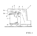
- Fig. 1 shows a delivery unit in a sheet-fed rotary printing press according to an embodiment of the present invention.
- a pair of sprockets 3 are rotatably provided to the rear portion, in the sheet conveying direction, of a pair of opposing frames 2a and 2b of a delivery unit 1.
- a pair of sprockets 4 are rotatably provided to the front portion, in the sheet convey direction, of the frames 2a and 2b.
- a pair of delivery chains 5 extend between the sprockets 3 and 4.
- Gripper bars 6 extend between the delivery chains 5 at a predetermined pitch.
- Each gripper bar 6 is provided with a gripper unit (not shown) composed of a gripper and a gripper pad.
- a sheet 7 printed by the printing apparatus main body is conveyed in a direction of arrow A as it is gripped by the gripper units.
- the sheet 7 is released from the gripper units, dropped onto a pile board 8 and stacked on it.
- the sheets 7 dropped and stacked on the pile board 8 are aligned in the vertical direction by their leading ends abutting against a paper lay 9, and in the horizontal direction by a side jogger plate 10.
- a suction unit 12 is provided upstream of the conveying terminal end of the delivery unit 1 to reduce the traveling inertia of the sheet 7 under transfer to the pile board 8.
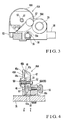
- the suction unit 12 will be described with reference to Figs. 2A and 2B.
- the suction unit 12 is provided with a pair of opposing frames 15 and 16.
- a pair of stays 17 and 18 extend between the frames 15 and 16, and a shaft 19 also horizontally extends between the frames 15 and 16.
- the shaft 19 is rotated by a drive unit (not shown) to move the suction unit 12 in the vertical direction of the sheet 7.
- a shaft 22 of a motor 21 fixed to the frame 16 is connected, through a coupling 23, to the projecting end, projecting from the frame 16, of a drive shaft 20 rotatably supported between the frames 15 and 16.
- a support 24 extending between the stays 17 and 18 supports the shaft 19 and rotatably, axially supports the drive shaft 20 through a bearing.
- a support plate 26 is attached to the outer side of the frame 15 through studs 25, and a cylindrical operation shaft 27 is rotatably supported by the support plate 26.
- a handle 28 is axially mounted on one end of the operation shaft 27 which projects from the support plate 26, and one end of a connecting shaft 29 is fitted in and fixed to the other end of the operation shaft 27.
- the connecting shaft 29 is rotatably supported in a through hole 30b extending through the operation shaft movement adjusting member 30 in the axial direction.
- a pair of rings 32 are axially mounted on the connecting shaft 29 to sandwich the two ends of the operation shaft movement adjusting member 30, thereby regulating the movement of the connecting shaft 29 in the axial direction (the direction of the arrows B - C).
- a pointer 33 is attached to the connecting shaft 29 such that it moves together with the connecting shaft 29 when the connecting shaft 29 moves in the axial direction, while it is rotatable when the connecting shaft 29 moves in the rotating direction.
- a scale 34 is formed on the stay 17 to correspond to the distal end of the pointer 33.
- the other end of the connecting shaft 29 is connected to one end of a first screw rod 35 through a connecting member 36.
- the axis of the first screw rod 35 coincides with that of the connecting shaft 29.
- the first screw rod 35 rotates together with the connecting shaft 29.
- the other end of the first screw rod 35 is connected to one end of a second screw rod 37.
- the axis of the second screw rod 37 coincides with that of the first screw rod 35.
- the second screw rod 37 rotates together with the first screw rod 35.
- the other end of a shaft portion 37a which corresponds to a portion of the second screw rod 37 extending from substantially its center to the other end not formed with a threaded portion, is connected to one end of a third screw rod 39 through a connecting member 38.
- the axis of the third screw rod 39 coincides with that of the shaft portion 37a.
- the third screw rod 39 rotates together with the shaft portion 37a.
- the other end of the third screw rod 39 is connected to one end of a fourth screw rod 40.
- the axis of the fourth screw rod 40 coincides with that of the third screw rod 39.
- the fourth screw rod 40 rotates together with the third screw rod 39.
- the other end of the fourth screw rod 40 is connected to one end of a shaft 42 through a connecting member 41.
- the axis of the shaft 42 coincides with that of the fourth screw rod 40.
- the shaft 42 rotates together with the fourth screw rod 40.
- the shaft 42, the shaft portion 37a of the second screw rod 37, and the connecting shaft 29 are rotatably supported through the support 24 extending between the stays 17 and 18, and another support (not shown).
- the pitches of the first and fourth screw rods 35 and 40 located on two end sides of the frames 15 and 16 are set to be substantially twice those of the second and third screw rods 37 and 39, respectively, located at the center of the frames 15 and 16.
- the first and second screw rods 35 and 37 form right-hand threads
- the third and fourth screw rods 39 and 40 form left-hand screws.
- suction wheel units 45A, 45B, 45D, and 45E are axially mounted on the first to fourth screw rods 35, 37, 39, and 40, and the shaft portion 37a of the second screw rod 37, respectively.
- the suction wheel units 45A to 45E have the same structure.
- the suction wheel unit 45A is constituted by a suction wheel 46A, a duct 47, and a lid 48 interposed between the duct 47 and suction wheel 46A.
- the suction wheel 46A is formed with a large number of slit-like air paths 46a in the rotational direction of the suction wheel 46A at the equal pitch.
- One side surface and a circumferential end face of each air path 46a are open.
- the openings in the circumferential end face of the suction wheel 46A form suction holes 46b.
- the (large number of) suction holes 46b are formed in the circumferential surface of the suction wheel 46A at the equal pitch.
- the lid 48 is made of a flat plate having substantially the same outer diameter as the outer diameter of the suction wheel 46A, and a window 48a having a semicircular shape when seen from the side surface is formed in the upper portion of the lid 48.
- the duct 47 is formed with a hollow portion 47a having one side surface that opens to the lid 48.
- the lid 48 is fixed to the duct 47 with a set screw 49 such that its window 48a opposes the hollow portion 47a.
- a screw 51 is fitted in the center hole of the suction wheel 46A through a sleeve 50, and the screw 51 extends also through the center hole of the duct 47.
- the suction wheel unit 45A is fixed to a support 55A with a screw 57 having a knob 56.
- a bush 58 formed with a threaded portion to threadably engage with the first screw rod 35 is fitted on and fixed to the support 55A such that its circumferential movement is regulated by a rotation preventive member 58a.
- a paper guide 53 is screwed to the duct 47.
- the second, third, and fourth screw rods 37, 39, and 40 respectively threadably engage with the threaded portions of bushes 58 of supports 55B, 55D, and 55E of the suction wheel units 45B, 45D, and 45E.
- a through hole (not shown) where the shaft portion 37a of the second screw rod 37 is to be inserted is formed in a support 55C of the central suction wheel unit 45C.
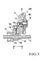
- the arrangement of the suction wheel unit 45B will be described with reference to Fig. 5.
- the suction wheel unit 45D is identical to the suction wheel unit 45B.
- the suction wheel unit 45B is different from the suction wheel unit 45A in that the suction wheel unit 45B can be adjusted to be movable in the direction of the arrows B - C.
- a support 54B is integrated with the duct 47 by a set screw 54a.
- the small-diameter portion 53a of the paper guide 53 extends through a through hole formed in the lower portion of the support 54B.
- This support 54B is sandwiched by a removal preventive ring 54b and a step 53b of the pivotal member 53, and moves together with the pivotal member 53 in the direction of the arrows B - C.
- a bolt 54c threadably engages with the support 54B.
- the pivotal member 53 is fixed to the support 54B by screwing the bolt 54c.
- the bolt 54c is loosened, the pivotal member 53 can pivot.
- the suction wheel unit 45B is movably adjusted in the direction of the arrows B - C through the support 54B.
- a hollow portion 55c extending in the back-and-forth direction of the sheet is formed in the lower portion of the support 55A.
- One end side of the hollow portion 55c communicates with the hollow portion 47a of the duct 47.
- An opening formed at the other end side of the support 55C is connected to one end of a hose 59 which is connected to a suction air source (not shown) at its other end.
- the air paths 46a of the suction wheel 46A, the window 48a of the lid 48, the hollow portion 47a of the duct 47, the hollow portion 55c of the support 55A, and the hose 59 communicate with each other.
- the outer air near the suction holes 46b of the suction wheel 46A is drawn by the suction air source through the air paths 46a, the window 48a, the hollow portion 47a of the duct 47, the hollow portion 55c of the support 55A, and the hose 59, to attract the sheet 7 by the circumferential surface of the suction wheel 46A.
- the hose 59 is made of a flexible member and connected to the suction air source with a margin. Accordingly, even when the suction wheel unit 45A is moved as will be described later, the hose 59 is kept connected to the suction air source.
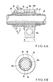
- FIG. 6A A structure for rotatably driving the suction wheel 46A will be described with reference to Figs. 6A and 6B, and Fig. 7.
- the diameter of the through hole 55b of the support 55A is larger than the diameter of the drive shaft 20, and a bearing 60 is arranged in the through hole 55b.
- the sleeve 62 fitted on the drive shaft 20 has a two-forked portion on which a spring 66 is wound. As shown in Fig. 6B, these portions constitute a pair of arcuate rotation transmitting portions 62a opposing each other.
- the sleeve 62 is inserted in the through hole 55b of the support 55A through the bearing 60.
- the support 55A is sandwiched by a pair of removal preventing rings 63 fixed to the sleeve 62, to regulate the axial movement of the sleeve 62 with respect to the support 55A.
- a pair of arcuate holders 65 having an outer diameter slightly larger than the outer diameter of the rotation transmitting portions 62a are interposed between the rotation transmitting portions 62a of the sleeve 62.
- the spring 66 is wound on the holders 65 to press them against the drive shaft 20 with its fastening force. Since the spring 66 fastens the holders 65, the holders 65 integrally rotate to follow rotation of the drive shaft 20. As the holders 65 rotate, the pair of rotation transmitting portions 62a also rotate to transmit rotation of the drive shaft 20 to the sleeve 62.
- a gear 68 which rotates together with the sleeve 62 is fitted on and fixed to one end of the sleeve 62 through a bush 67.
- the gear 68 having teeth at the same pitch as that of the suction holes 46b of the suction wheel 46A meshes with the suction holes 46b.
- the gear 68 rotates through the holders 65 and sleeve 62, so that the suction wheel 46A also rotates about the sleeve 50 as the rotation center, as shown in Fig. 4.
- the outer diameter of the rotation transmitting portions 62a of the sleeve 62 is smaller than the outer diameter of the holders 65. Therefore, the sleeve 62 is supported to be movable with respect to the drive shaft 20 in the axial direction, i.e., in the widthwise direction (the direction of arrows B - C) of the sheet.
- the sleeve 62 and the support 55, the axial movement of which is regulated, can also move with respect to the drive shaft 20 in the direction of arrows B - C.
- the sheet 7 is gripped by the gripper units of the pair of delivery chains 5 and conveyed to the delivery sheet pile board 8.
- the suction wheels 46A to 46E At the convey terminal end, when the gripped end of the sheet 7 passes the suction wheels 46A to 46E, the sheet 7 travels in slidable contact with the suction wheels 46A to 46E.
- the respective gears 68 upon rotation of the motor 21 and drive shaft 20, the respective gears 68 also rotate through the respective sleeves 62 of the suction wheel units 45A to 45E, thereby rotating the suction wheels 46A to 46E.
- the outer air near the suction wheels 46A to 46E is drawn by the suction air source (not shown) through the suction holes 46b. Therefore, the sheet 7 is conveyed as it is attached to the circumferential surfaces of the suction wheels 46A to 46E.
- the speed of the sheet 7 at portions other than its gripped side becomes lower than the conveying speed, and the sheet 7 is kept taut in the horizontal state. Accordingly, the traveling inertia of the sheet 7 is attenuated, and the sheets dropped and stacked on the pile board 8 are aligned well.
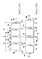
- FIG. 8A when four-surface printing is to be performed to print an image on the sheet 7, four image areas 70A to 70D and five non-image areas 71A to 71E are assigned to the sheet 7.
- the suction wheels 46A to 46E are positioned to respectively correspond to the non-image areas 71A to 71E.
- the suction wheels 46B and 46D are removed by rotating the knobs 56 of the screws 57 of the corresponding supports 55 to disengage the screws 57 from the ducts 47, and the suction wheel units 45B and 45D are removed from their supports 55.
- the suction wheels 46B and 46D corresponding to the image areas 72A and 72B can be easily removed by rotating the knobs 56, leading to improved operability.
- image plate making of the sheet 7 is determined as four-surface printing, and the four image areas 70A to 70D and the five non-image areas 71A to 71E are assigned to the sheet 7.
- the suction wheels 46A to 46E are positioned to correspond to the non-image areas 71A to 71E.
- non-image areas 73A, 73B, 73D, and 73E are assigned with a larger span than that of the non-image areas 71A, 71B, 71D, and 71E of the sheet 7 with reference to a center G - G in the widthwise direction of the sheet.
- the non-image areas 73D and 73E are assigned at positions shifted from the non-image areas 71D and 71E, located to the left from the center G - G in the widthwise direction of the sheet, to the left by distances L and 2L, respectively.
- the non-image areas 73A and 73B are assigned at positions shifted from the non-image areas 71A and 71B, located to the right from the center G - G in the widthwise direction of the sheet, to the right by distances L and 2L, respectively.
- the handle 28 is rotated to rotate the operation shaft 27, thereby rotating the first to fourth screw rods 35, 37, 39, and 40 through the connecting shaft 29.
- the respective supports 55 of the suction wheel units 45A to 45E are supported by the drive shaft 20 through the sleeve 62 to be movable in the direction of the arrows B - C.
- the supports 55, the bushes 58 of which threadably engage with the screw rods 35, 37, 39, and 40 move in the direction of the arrows B - C as they are guided by the drive shaft 20.
- the first and second screw rods 35 and 37 located to the right (direction of the arrow C) from the center form right-hand threads
- the third and fourth screw rods 39 and 40 located to the left (direction of the arrow B) from the center form left-hand threads.
- the suction wheel units 45A and 45B move in the direction of the arrow C.
- the suction wheel units 45D and 45E move in the direction of the arrow B.
- the pitches of the first and fourth screw rods 35 and 40 serving as the outer screw rods are twice those of the second and third screw rods 37 and 39 serving as the inner screw rods.
- the operability can be increased. Since the suction wheel positioning operation is performed by the handle 28 provided at the outside of the suction wheel units, the operability can be better than that of the conventional positioning operation performed inside the suction wheel units.
- the handle 28 is pivoted to move the suction wheel units 45A to 45E to the margins (non-image areas) on the two ends of the sheet.
- the bolts 54c (Fig. 5) of the suction wheel units 45B and 45D are loosened, and the pivotal members 53 are moved to move the suction wheel units 45B and 45D in the sheet widthwise direction (the direction of arrows B - C) separately.
- the bolts 54c are fastened.
- the knobbed screw 57 of the central suction wheel unit 45C is loosened to remove the suction wheel unit 45C from the support 55.
- the suction wheel units 45A, 45B, 45D, and 45E are positioned in the non-image areas of the sheet.
- the set screw 31 (Fig. 2A) is loosened and the head 30a of the operation shaft movement adjusting member 30 is rotated with a spanner or the like to move the operation shaft movement adjusting member 30 in the direction of the arrows B - C.
- the connecting shaft 29 is moved in the direction of the arrows B - C through the pair of rings 32, and the screw rods 35, 37, 39, and 40 are also moved at once in the direction of the arrows B - C by the same amount.
- the suction wheels 46A to 46E can be positioned in the non-image areas 71A to 71E.
- the adjusting operation is easy, and the suction wheels 46A to 46E will not erroneously come into slidable contact with the ink of a printed portion, so that the printing quality can be improved.
- the positional error amount of the suction wheel 46 on the sheet 7 as the positional error amount of the plate may be set by using the pointer 33 and scale 34. This can decrease the number of times of test printing to decrease the amount of wasted paper. Since the adjusting operation can be performed simply within a short period of time, the productivity is improved.
- air ducts may be mounted on the supports 55 in place of the suction wheels 46A to 46E. In this case, if air is blown from the air ducts toward the outer side or upper side of the sheet widthwise direction, slacking of the sheet at the intermediate portion can be prevented.
- the sheet 7 can be any sheet-like printing product including a film.
- the suction members can be removed from the suction wheel units, a suction member which is not in use can be handled easily. Since another suction member, a paper receiving wheel, and the like can be attached and detached easily, the printing press can cope with various types of printing, leading to improved versatility. Since the suction members can be rotatably driven with one drive shaft by utilizing the suction holes of the suction surfaces, the structure is simplified.
Landscapes
- Engineering & Computer Science (AREA)
- Mechanical Engineering (AREA)
- Sheets, Magazines, And Separation Thereof (AREA)
- Supply, Installation And Extraction Of Printed Sheets Or Plates (AREA)
- Delivering By Means Of Belts And Rollers (AREA)
- Separation, Sorting, Adjustment, Or Bending Of Sheets To Be Conveyed (AREA)
Applications Claiming Priority (4)
| Application Number | Priority Date | Filing Date | Title |
|---|---|---|---|
| JP26188698 | 1998-09-16 | ||
| JP26188698A JP4130501B2 (ja) | 1998-09-16 | 1998-09-16 | 枚葉輪転印刷機における吸引装置 |
| JP26190598 | 1998-09-16 | ||
| JP10261905A JP2000086046A (ja) | 1998-09-16 | 1998-09-16 | 枚葉輪転印刷機における吸引装置 |
Publications (3)
| Publication Number | Publication Date |
|---|---|
| EP0987108A2 true EP0987108A2 (de) | 2000-03-22 |
| EP0987108A3 EP0987108A3 (de) | 2000-12-06 |
| EP0987108B1 EP0987108B1 (de) | 2004-03-03 |
Family
ID=26545287
Family Applications (1)
| Application Number | Title | Priority Date | Filing Date |
|---|---|---|---|
| EP99250326A Expired - Lifetime EP0987108B1 (de) | 1998-09-16 | 1999-09-16 | Saugaggregat in einer Bogenrotationsdruckmaschine |
Country Status (5)
| Country | Link |
|---|---|
| US (1) | US6264190B1 (de) |
| EP (1) | EP0987108B1 (de) |
| AT (1) | ATE260767T1 (de) |
| DE (1) | DE69915198T2 (de) |
| ES (1) | ES2217688T3 (de) |
Families Citing this family (4)
| Publication number | Priority date | Publication date | Assignee | Title |
|---|---|---|---|---|
| JP4878104B2 (ja) * | 2003-07-21 | 2012-02-15 | ハイデルベルガー ドルツクマシーネン アクチエンゲゼルシヤフト | 印刷機を通じて枚葉紙を搬送するための方法および該方法を実施するための装置 |
| JP2007070075A (ja) * | 2005-09-08 | 2007-03-22 | Komori Corp | 枚葉輪転印刷機における排紙装置 |
| CN1939827B (zh) * | 2005-09-30 | 2010-08-04 | 海德堡印刷机械股份公司 | 用于将页张输送到堆垛上的方法 |
| EP3013722B1 (de) * | 2013-12-04 | 2020-03-18 | Koenig & Bauer AG | Verfahren zum einstellen zumindest eines bremselementes einer bogenbremse, und verwendung eines druckfreien abschnittes eines bedruckstoffes zum verzögern des bedruckstoffes durch ein bremselement |
Citations (7)
| Publication number | Priority date | Publication date | Assignee | Title |
|---|---|---|---|---|
| DE944857C (de) * | 1953-02-04 | 1956-06-28 | Maschf Augsburg Nuernberg Ag | Vorrichtung zum Bogenablegen, insbesondere bei Druckmaschinen |
| FR1592001A (de) * | 1967-11-17 | 1970-05-04 | ||
| DE2811963A1 (de) * | 1978-03-18 | 1979-09-27 | Heidelberger Druckmasch Ag | Bogenauslagevorrichtung an druckmaschinen |
| DE3413179A1 (de) * | 1984-04-07 | 1985-10-24 | Miller-Johannisberg Druckmaschinen Gmbh, 6200 Wiesbaden | Steuer- und regelvorrichtung eines bogenauslegers fuer bogenverarbeitende maschinen, insbesondere fuer bogendruckmaschinen |
| EP0178470A2 (de) * | 1984-10-13 | 1986-04-23 | Heidelberger Druckmaschinen Aktiengesellschaft | Bogenauslagevorrichtung an Druckmaschinen |
| DE4035036A1 (de) * | 1990-11-03 | 1992-05-07 | Planeta Druckmaschinenwerk Ag | Einrichtung zur axialen einstellung von saugringen in bogenbremsen von druckmaschinen |
| EP0693449A2 (de) * | 1994-07-22 | 1996-01-24 | MAN Roland Druckmaschinen AG | Bogenbremse im Ausleger einer Druckmaschine |
Family Cites Families (3)
| Publication number | Priority date | Publication date | Assignee | Title |
|---|---|---|---|---|
| US2474997A (en) * | 1947-02-21 | 1949-07-05 | Miehle Printing Press & Mfg | Sheet delivery controlling method and means therefor |
| GB662947A (en) * | 1949-02-02 | 1951-12-12 | Harris Seybold Co | Improvements in or relating to a sheet delivery mechanism for machines such as printing machines |
| DE2544566C3 (de) * | 1975-10-04 | 1984-11-15 | Miller Printing Equipment Corp., Pittsburgh, Pa. | Bogenausleger für Bogendruckmaschinen |
-
1999
- 1999-09-16 US US09/397,406 patent/US6264190B1/en not_active Expired - Fee Related
- 1999-09-16 ES ES99250326T patent/ES2217688T3/es not_active Expired - Lifetime
- 1999-09-16 AT AT99250326T patent/ATE260767T1/de not_active IP Right Cessation
- 1999-09-16 EP EP99250326A patent/EP0987108B1/de not_active Expired - Lifetime
- 1999-09-16 DE DE69915198T patent/DE69915198T2/de not_active Expired - Fee Related
Patent Citations (7)
| Publication number | Priority date | Publication date | Assignee | Title |
|---|---|---|---|---|
| DE944857C (de) * | 1953-02-04 | 1956-06-28 | Maschf Augsburg Nuernberg Ag | Vorrichtung zum Bogenablegen, insbesondere bei Druckmaschinen |
| FR1592001A (de) * | 1967-11-17 | 1970-05-04 | ||
| DE2811963A1 (de) * | 1978-03-18 | 1979-09-27 | Heidelberger Druckmasch Ag | Bogenauslagevorrichtung an druckmaschinen |
| DE3413179A1 (de) * | 1984-04-07 | 1985-10-24 | Miller-Johannisberg Druckmaschinen Gmbh, 6200 Wiesbaden | Steuer- und regelvorrichtung eines bogenauslegers fuer bogenverarbeitende maschinen, insbesondere fuer bogendruckmaschinen |
| EP0178470A2 (de) * | 1984-10-13 | 1986-04-23 | Heidelberger Druckmaschinen Aktiengesellschaft | Bogenauslagevorrichtung an Druckmaschinen |
| DE4035036A1 (de) * | 1990-11-03 | 1992-05-07 | Planeta Druckmaschinenwerk Ag | Einrichtung zur axialen einstellung von saugringen in bogenbremsen von druckmaschinen |
| EP0693449A2 (de) * | 1994-07-22 | 1996-01-24 | MAN Roland Druckmaschinen AG | Bogenbremse im Ausleger einer Druckmaschine |
Also Published As
| Publication number | Publication date |
|---|---|
| US6264190B1 (en) | 2001-07-24 |
| DE69915198T2 (de) | 2004-10-14 |
| ATE260767T1 (de) | 2004-03-15 |
| ES2217688T3 (es) | 2004-11-01 |
| EP0987108B1 (de) | 2004-03-03 |
| DE69915198D1 (de) | 2004-04-08 |
| EP0987108A3 (de) | 2000-12-06 |
Similar Documents
| Publication | Publication Date | Title |
|---|---|---|
| US4225129A (en) | Sheet guidance arrangement in printing-machine outfeed units | |
| JPH1110833A (ja) | 枚葉紙輪転機 | |
| JP5379525B2 (ja) | シート状物の品質検査装置 | |
| JPH062403B2 (ja) | 輪転印刷機の印刷部間に配置される渡しドラム | |
| JPS60232958A (ja) | 枚葉紙輪転印刷機 | |
| JP4334073B2 (ja) | 枚葉紙印刷機 | |
| EP0563746B1 (de) | Bogenwendeeinrichtung in einer Rotationsdruckmaschine | |
| US7261291B2 (en) | Sheet-processing rotary press with a delivery containing after-grippers | |
| US4821643A (en) | Switchable sheet fed rotary printing press | |
| EP0987108B1 (de) | Saugaggregat in einer Bogenrotationsdruckmaschine | |
| JP4856304B2 (ja) | 枚葉紙印刷機用枚葉紙案内装置 | |
| JP2000053303A5 (de) | ||
| US6581928B1 (en) | Sheet guide device for sheet-processing machine | |
| EP1225043A2 (de) | Einrichtung zur Wendung flächiger Exemplare in halbtourigen bogenverarbeitenden Maschinen | |
| JPH04224949A (ja) | 多色・枚葉紙輪転印刷機における枚葉紙渡しドラムに設けられた吸込制御装置 | |
| US6089158A (en) | Printing press with delivery including independently mounted sprockets | |
| JP4450890B2 (ja) | 枚葉紙輪転印刷機 | |
| DE19949751A1 (de) | Modulares Druckmaschinensystem zum Bedrucken von Bogen | |
| EP1006068B1 (de) | Ausleger einer Bogen verarbeitenden Maschine | |
| JPH02235637A (ja) | 枚葉紙反転装置 | |
| JP3624881B2 (ja) | サテライト型印刷機のシート反転装置 | |
| JP4130501B2 (ja) | 枚葉輪転印刷機における吸引装置 | |
| JP4443826B2 (ja) | 加工処理機のための可動ガイド面を備えた枚葉紙ガイド装置 | |
| US5341738A (en) | Device for transporting sheets within a printing machine | |
| DE19723146C2 (de) | Bogenweiche zur Unterstützung der Bogenführung |
Legal Events
| Date | Code | Title | Description |
|---|---|---|---|
| PUAI | Public reference made under article 153(3) epc to a published international application that has entered the european phase |
Free format text: ORIGINAL CODE: 0009012 |
|
| AK | Designated contracting states |
Kind code of ref document: A2 Designated state(s): AT BE CH CY DE DK ES FI FR GB GR IE IT LI LU MC NL PT SE |
|
| AX | Request for extension of the european patent |
Free format text: AL;LT;LV;MK;RO;SI |
|
| PUAL | Search report despatched |
Free format text: ORIGINAL CODE: 0009013 |
|
| AK | Designated contracting states |
Kind code of ref document: A3 Designated state(s): AT BE CH CY DE DK ES FI FR GB GR IE IT LI LU MC NL PT SE |
|
| AX | Request for extension of the european patent |
Free format text: AL;LT;LV;MK;RO;SI |
|
| RIC1 | Information provided on ipc code assigned before grant |
Free format text: 7B 41F 21/08 A, 7B 65H 29/68 B, 7B 41F 21/00 B |
|
| 17P | Request for examination filed |
Effective date: 20010504 |
|
| AKX | Designation fees paid |
Free format text: AT BE CH CY DE DK ES FI FR GB GR IE IT LI LU MC NL PT SE |
|
| 17Q | First examination report despatched |
Effective date: 20020124 |
|
| GRAP | Despatch of communication of intention to grant a patent |
Free format text: ORIGINAL CODE: EPIDOSNIGR1 |
|
| GRAS | Grant fee paid |
Free format text: ORIGINAL CODE: EPIDOSNIGR3 |
|
| GRAA | (expected) grant |
Free format text: ORIGINAL CODE: 0009210 |
|
| AK | Designated contracting states |
Kind code of ref document: B1 Designated state(s): AT BE CH CY DE DK ES FI FR GB GR IE IT LI LU MC NL PT SE |
|
| PG25 | Lapsed in a contracting state [announced via postgrant information from national office to epo] |
Ref country code: FI Free format text: LAPSE BECAUSE OF FAILURE TO SUBMIT A TRANSLATION OF THE DESCRIPTION OR TO PAY THE FEE WITHIN THE PRESCRIBED TIME-LIMIT Effective date: 20040303 Ref country code: CY Free format text: LAPSE BECAUSE OF FAILURE TO SUBMIT A TRANSLATION OF THE DESCRIPTION OR TO PAY THE FEE WITHIN THE PRESCRIBED TIME-LIMIT Effective date: 20040303 Ref country code: BE Free format text: LAPSE BECAUSE OF FAILURE TO SUBMIT A TRANSLATION OF THE DESCRIPTION OR TO PAY THE FEE WITHIN THE PRESCRIBED TIME-LIMIT Effective date: 20040303 Ref country code: AT Free format text: LAPSE BECAUSE OF FAILURE TO SUBMIT A TRANSLATION OF THE DESCRIPTION OR TO PAY THE FEE WITHIN THE PRESCRIBED TIME-LIMIT Effective date: 20040303 |
|
| REG | Reference to a national code |
Ref country code: GB Ref legal event code: FG4D |
|
| REG | Reference to a national code |
Ref country code: CH Ref legal event code: EP |
|
| REG | Reference to a national code |
Ref country code: SE Ref legal event code: TRGR |
|
| REG | Reference to a national code |
Ref country code: IE Ref legal event code: FG4D |
|
| REF | Corresponds to: |
Ref document number: 69915198 Country of ref document: DE Date of ref document: 20040408 Kind code of ref document: P |
|
| PG25 | Lapsed in a contracting state [announced via postgrant information from national office to epo] |
Ref country code: GR Free format text: LAPSE BECAUSE OF FAILURE TO SUBMIT A TRANSLATION OF THE DESCRIPTION OR TO PAY THE FEE WITHIN THE PRESCRIBED TIME-LIMIT Effective date: 20040603 Ref country code: DK Free format text: LAPSE BECAUSE OF FAILURE TO SUBMIT A TRANSLATION OF THE DESCRIPTION OR TO PAY THE FEE WITHIN THE PRESCRIBED TIME-LIMIT Effective date: 20040603 |
|
| REG | Reference to a national code |
Ref country code: CH Ref legal event code: NV Representative=s name: LUCHS & PARTNER PATENTANWAELTE |
|
| PG25 | Lapsed in a contracting state [announced via postgrant information from national office to epo] |
Ref country code: LU Free format text: LAPSE BECAUSE OF NON-PAYMENT OF DUE FEES Effective date: 20040916 Ref country code: IE Free format text: LAPSE BECAUSE OF NON-PAYMENT OF DUE FEES Effective date: 20040916 |
|
| PG25 | Lapsed in a contracting state [announced via postgrant information from national office to epo] |
Ref country code: MC Free format text: LAPSE BECAUSE OF NON-PAYMENT OF DUE FEES Effective date: 20040930 |
|
| ET | Fr: translation filed | ||
| REG | Reference to a national code |
Ref country code: ES Ref legal event code: FG2A Ref document number: 2217688 Country of ref document: ES Kind code of ref document: T3 |
|
| PLBE | No opposition filed within time limit |
Free format text: ORIGINAL CODE: 0009261 |
|
| STAA | Information on the status of an ep patent application or granted ep patent |
Free format text: STATUS: NO OPPOSITION FILED WITHIN TIME LIMIT |
|
| 26N | No opposition filed |
Effective date: 20041206 |
|
| REG | Reference to a national code |
Ref country code: IE Ref legal event code: MM4A |
|
| PGFP | Annual fee paid to national office [announced via postgrant information from national office to epo] |
Ref country code: FR Payment date: 20050823 Year of fee payment: 7 |
|
| PGFP | Annual fee paid to national office [announced via postgrant information from national office to epo] |
Ref country code: SE Payment date: 20050906 Year of fee payment: 7 |
|
| PGFP | Annual fee paid to national office [announced via postgrant information from national office to epo] |
Ref country code: DE Payment date: 20050909 Year of fee payment: 7 |
|
| PGFP | Annual fee paid to national office [announced via postgrant information from national office to epo] |
Ref country code: GB Payment date: 20050914 Year of fee payment: 7 Ref country code: CH Payment date: 20050914 Year of fee payment: 7 |
|
| PGFP | Annual fee paid to national office [announced via postgrant information from national office to epo] |
Ref country code: NL Payment date: 20050915 Year of fee payment: 7 |
|
| PGFP | Annual fee paid to national office [announced via postgrant information from national office to epo] |
Ref country code: ES Payment date: 20051027 Year of fee payment: 7 |
|
| PG25 | Lapsed in a contracting state [announced via postgrant information from national office to epo] |
Ref country code: SE Free format text: LAPSE BECAUSE OF NON-PAYMENT OF DUE FEES Effective date: 20060917 |
|
| PG25 | Lapsed in a contracting state [announced via postgrant information from national office to epo] |
Ref country code: LI Free format text: LAPSE BECAUSE OF NON-PAYMENT OF DUE FEES Effective date: 20060930 Ref country code: CH Free format text: LAPSE BECAUSE OF NON-PAYMENT OF DUE FEES Effective date: 20060930 |
|
| PGFP | Annual fee paid to national office [announced via postgrant information from national office to epo] |
Ref country code: IT Payment date: 20060930 Year of fee payment: 8 |
|
| PG25 | Lapsed in a contracting state [announced via postgrant information from national office to epo] |
Ref country code: NL Free format text: LAPSE BECAUSE OF NON-PAYMENT OF DUE FEES Effective date: 20070401 |
|
| PG25 | Lapsed in a contracting state [announced via postgrant information from national office to epo] |
Ref country code: DE Free format text: LAPSE BECAUSE OF NON-PAYMENT OF DUE FEES Effective date: 20070403 |
|
| REG | Reference to a national code |
Ref country code: CH Ref legal event code: PL |
|
| EUG | Se: european patent has lapsed | ||
| GBPC | Gb: european patent ceased through non-payment of renewal fee |
Effective date: 20060916 |
|
| NLV4 | Nl: lapsed or anulled due to non-payment of the annual fee |
Effective date: 20070401 |
|
| REG | Reference to a national code |
Ref country code: FR Ref legal event code: ST Effective date: 20070531 |
|
| PG25 | Lapsed in a contracting state [announced via postgrant information from national office to epo] |
Ref country code: GB Free format text: LAPSE BECAUSE OF NON-PAYMENT OF DUE FEES Effective date: 20060916 |
|
| REG | Reference to a national code |
Ref country code: ES Ref legal event code: FD2A Effective date: 20060918 |
|
| PG25 | Lapsed in a contracting state [announced via postgrant information from national office to epo] |
Ref country code: PT Free format text: LAPSE BECAUSE OF NON-PAYMENT OF DUE FEES Effective date: 20040803 |
|
| PG25 | Lapsed in a contracting state [announced via postgrant information from national office to epo] |
Ref country code: ES Free format text: LAPSE BECAUSE OF NON-PAYMENT OF DUE FEES Effective date: 20060918 |
|
| PG25 | Lapsed in a contracting state [announced via postgrant information from national office to epo] |
Ref country code: FR Free format text: LAPSE BECAUSE OF NON-PAYMENT OF DUE FEES Effective date: 20061002 |
|
| PG25 | Lapsed in a contracting state [announced via postgrant information from national office to epo] |
Ref country code: IT Free format text: LAPSE BECAUSE OF NON-PAYMENT OF DUE FEES Effective date: 20070916 |