EP0985814B1 - Verfahren und Vorrichtung zur Steuerung wenigstens eines Magnetventils - Google Patents
Verfahren und Vorrichtung zur Steuerung wenigstens eines Magnetventils Download PDFInfo
- Publication number
- EP0985814B1 EP0985814B1 EP99107944A EP99107944A EP0985814B1 EP 0985814 B1 EP0985814 B1 EP 0985814B1 EP 99107944 A EP99107944 A EP 99107944A EP 99107944 A EP99107944 A EP 99107944A EP 0985814 B1 EP0985814 B1 EP 0985814B1
- Authority
- EP
- European Patent Office
- Prior art keywords
- voltage
- booster
- switch
- basis
- solenoid valve
- Prior art date
- Legal status (The legal status is an assumption and is not a legal conclusion. Google has not performed a legal analysis and makes no representation as to the accuracy of the status listed.)
- Expired - Lifetime
Links
Images

Classifications
-
- H—ELECTRICITY
- H01—ELECTRIC ELEMENTS
- H01F—MAGNETS; INDUCTANCES; TRANSFORMERS; SELECTION OF MATERIALS FOR THEIR MAGNETIC PROPERTIES
- H01F7/00—Magnets
- H01F7/06—Electromagnets; Actuators including electromagnets
- H01F7/08—Electromagnets; Actuators including electromagnets with armatures
- H01F7/18—Circuit arrangements for obtaining desired operating characteristics, e.g. for slow operation, for sequential energisation of windings, for high-speed energisation of windings
- H01F7/1805—Circuit arrangements for holding the operation of electromagnets or for holding the armature in attracted position with reduced energising current
- H01F7/1816—Circuit arrangements for holding the operation of electromagnets or for holding the armature in attracted position with reduced energising current making use of an energy accumulator
-
- F—MECHANICAL ENGINEERING; LIGHTING; HEATING; WEAPONS; BLASTING
- F02—COMBUSTION ENGINES; HOT-GAS OR COMBUSTION-PRODUCT ENGINE PLANTS
- F02D—CONTROLLING COMBUSTION ENGINES
- F02D41/00—Electrical control of supply of combustible mixture or its constituents
- F02D41/20—Output circuits, e.g. for controlling currents in command coils
- F02D2041/2003—Output circuits, e.g. for controlling currents in command coils using means for creating a boost voltage, i.e. generation or use of a voltage higher than the battery voltage, e.g. to speed up injector opening
- F02D2041/2006—Output circuits, e.g. for controlling currents in command coils using means for creating a boost voltage, i.e. generation or use of a voltage higher than the battery voltage, e.g. to speed up injector opening by using a boost capacitor
-
- F—MECHANICAL ENGINEERING; LIGHTING; HEATING; WEAPONS; BLASTING
- F02—COMBUSTION ENGINES; HOT-GAS OR COMBUSTION-PRODUCT ENGINE PLANTS
- F02D—CONTROLLING COMBUSTION ENGINES
- F02D41/00—Electrical control of supply of combustible mixture or its constituents
- F02D41/20—Output circuits, e.g. for controlling currents in command coils
- F02D2041/2003—Output circuits, e.g. for controlling currents in command coils using means for creating a boost voltage, i.e. generation or use of a voltage higher than the battery voltage, e.g. to speed up injector opening
- F02D2041/201—Output circuits, e.g. for controlling currents in command coils using means for creating a boost voltage, i.e. generation or use of a voltage higher than the battery voltage, e.g. to speed up injector opening by using a boost inductance
-
- F—MECHANICAL ENGINEERING; LIGHTING; HEATING; WEAPONS; BLASTING
- F02—COMBUSTION ENGINES; HOT-GAS OR COMBUSTION-PRODUCT ENGINE PLANTS
- F02D—CONTROLLING COMBUSTION ENGINES
- F02D41/00—Electrical control of supply of combustible mixture or its constituents
- F02D41/20—Output circuits, e.g. for controlling currents in command coils
- F02D2041/202—Output circuits, e.g. for controlling currents in command coils characterised by the control of the circuit
- F02D2041/2024—Output circuits, e.g. for controlling currents in command coils characterised by the control of the circuit the control switching a load after time-on and time-off pulses
- F02D2041/2027—Control of the current by pulse width modulation or duty cycle control
-
- F—MECHANICAL ENGINEERING; LIGHTING; HEATING; WEAPONS; BLASTING
- F02—COMBUSTION ENGINES; HOT-GAS OR COMBUSTION-PRODUCT ENGINE PLANTS
- F02D—CONTROLLING COMBUSTION ENGINES
- F02D41/00—Electrical control of supply of combustible mixture or its constituents
- F02D41/20—Output circuits, e.g. for controlling currents in command coils
- F02D2041/202—Output circuits, e.g. for controlling currents in command coils characterised by the control of the circuit
- F02D2041/2044—Output circuits, e.g. for controlling currents in command coils characterised by the control of the circuit using pre-magnetisation or post-magnetisation of the coils
-
- F—MECHANICAL ENGINEERING; LIGHTING; HEATING; WEAPONS; BLASTING
- F02—COMBUSTION ENGINES; HOT-GAS OR COMBUSTION-PRODUCT ENGINE PLANTS
- F02D—CONTROLLING COMBUSTION ENGINES
- F02D41/00—Electrical control of supply of combustible mixture or its constituents
- F02D41/20—Output circuits, e.g. for controlling currents in command coils
- F02D2041/202—Output circuits, e.g. for controlling currents in command coils characterised by the control of the circuit
- F02D2041/2058—Output circuits, e.g. for controlling currents in command coils characterised by the control of the circuit using information of the actual current value
-
- F—MECHANICAL ENGINEERING; LIGHTING; HEATING; WEAPONS; BLASTING
- F02—COMBUSTION ENGINES; HOT-GAS OR COMBUSTION-PRODUCT ENGINE PLANTS
- F02D—CONTROLLING COMBUSTION ENGINES
- F02D41/00—Electrical control of supply of combustible mixture or its constituents
- F02D41/20—Output circuits, e.g. for controlling currents in command coils
- F02D2041/2068—Output circuits, e.g. for controlling currents in command coils characterised by the circuit design or special circuit elements
- F02D2041/2075—Type of transistors or particular use thereof
Definitions
- the invention relates to a method and a device to control at least one solenoid valve according to the General terms of the independent claims.
- a method and a device for control at least one solenoid valve are from DE 195 39 071 known.
- the solenoid valve is used to control the fuel metering in a Internal combustion engine used. To accelerate The one connected to a booster capacitor is switched on Voltage applied to the consumer. This means that too Start controlling consumers with one opposite the further control increased voltage used Voltage is applied.
- the invention is based, with one Method and a device for controlling a Solenoid valve to reduce the power loss, whereby at the same time the effect of the switching time extension is kept as low as possible. This task is accomplished by the features characterized in the independent claims solved.
- the power loss can be significantly reduced, whereby the effects of the increased switching times thereby low are.
- Influencing energy or performance is preferably done over one or more of the sizes Booster voltage, booster current or booster time, in particular by lowering the booster voltage and / or the Booster current and / or the booster time in certain Operating states, the power loss is reduced.
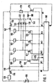
- FIG. 1 shows essential elements of the device according to the invention
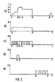
- FIG. 2 shows various signals plotted over time t
- Figure 3 shows a detail of the controller
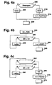
- Figure 4 different Embodiments shown as flow diagrams.
- the device according to the invention is preferred for internal combustion engines used. There is the fuel metering controlled by electromagnetic valves. This electromagnetic Valves are also referred to below Referred to consumers.
- Figure 1 are the most important elements of the invention Facility shown.
- it is a four-cylinder internal combustion engine. Every consumer has an injection valve and a cylinder of the internal combustion engine for each injection valve assigned. With higher numbers of cylinders of the internal combustion engine are accordingly more valves, switching means and To provide diodes.
- connection of the consumer 100 to 103 is over a common switching means 115, a diode 110 and one Measuring means 125 with a voltage supply 105 in Connection.
- the diode 110 is arranged so that it with its anode the switching means 115 and with its cathode with the Connected to consumers (100 to 103).
- Switching means 115 is preferably a Field effect transistor.
- the second connection for consumers 100 to 103 are each via a second switching means 120, 121, 122 and 123 in connection with a resistance means 125.
- the switching means 120 to 123 are also preferably around field effect transistors.
- the switching means 120 to 123 are used as low-side switches and the switching means 115 referred to as the highside switch.
- the second connection of the resistance means 125 is connected to the second connection the power supply in connection.
- Each consumer 100 to 103 has a diode 130, 131, 132 and 133 assigned.
- the anode connection of the diodes is in each case with the connection point between consumer and low-side switch in contact.
- the cathode connection is with a capacitor 145 and a further switching means 140 in connection.
- the second connection of the switching means 140 is connected via a diode 142 to the first terminals of the Consumers 100 to 103 in contact.
- This switching means 140 it is also preferably a Field effect transistor.
- This switching means 140 is also called Booster switch designated.
- the second connection of the Capacitor 145 is also connected to the second terminal the supply voltage 105 in connection.
- the highside switch 115 is operated by a control unit 160 with a control signal AH.
- the switching device 120 is sent by the control unit 160 with a control signal AL1, the switching means 121 with a drive signal AL2, the Switching means 122 with a control signal AL3, the switching means 123 with a control signal AL4 and the switching means 140 applied with a control signal AC.
- the Control unit 160 becomes the one applied to capacitor 145 Voltage supplied.
- the control unit 160 also evaluates the flows flowing through the consumer. To do this the voltage values USH0 and USH are recorded.
- Diode 150 switched between the second connection of the voltage supply 105 and the connection point between the diode 110 and the first connections of consumers 100 to 103 is one Diode 150 switched.
- the anode of the diode is included connected to the second connection of the voltage supply 105.
- Resistor 125 can be used by the consumer flowing current can be determined.
- the current measuring resistor 125 can also be arranged elsewhere.
- the second connection of the capacitor 145 to the Connection point between the current measuring means 125 and the Switching means 120 to 123 are connected. In this case is also a current measurement when the low-side switch is locked possible.
- the current measuring means between the Power supply and the highside switch or Im the first or second connection of the consumers can be arranged.
- Resistor 125 can be another resistor 126 between the first connection of the voltage supply 105 and the high-side switch 115 may be arranged. With this resistor 126 a current measurement can also be carried out.
- connection point between the switching means 140 and the Capacitor 145 is connected to the cathode of a further diode 180 in contact.
- the anode of diode 180 stands with the Connection point between an inductor 170 and one further switching means 175 in connection.
- the switching device 175 is also called a charging switch.
- a second Connection of the other switching means is with the second Connection of the capacitor 145 or with the second connection the supply voltage 105 in connection.
- the inductance 170 also stands with the first connection of the Supply voltage in connection.
- Inductor 170, charge switch 175 and diode 180 form a voltage converter. Instead of these items you can another embodiment of a voltage converter, in particular a DC / DC DC converter become.
- the charging switch is also from the Control unit 160 is supplied with a control signal AS.
- phase 1 Different phases are distinguished in each metering cycle.
- a phase 0 before the time t1, before the Control of the consumer is the final stage off.
- the control signals AC, AH and AL are located yourself at low potential. This means that the Highside switch 115, the low side switch 120 to 123 and the booster switch 140 block the flow of current.
- the capacitor 145 is on its maximum voltage UC charged, which is preferred is higher than the supply voltage Ubat. This takes for example a value of approx. 80 volts, whereas the Voltage of the power supply assumes a value of approx. 12 V.
- the high-side switch becomes the current, which is by means of the current measuring resistor 125 is recorded to a predeterminable value for the Pre-current flow IV regulated. That is, when reached of the target current IV for the starting current is Highside switch 115 controlled so that it blocks. When falling short another threshold is released again.
- the setpoint for the bias current IV is chosen that a magnetic field builds up in the consumer, but still not sufficient to switch the consumer.
- the first phase ends with the actual activation of the Consumer at time t2.
- a second phase is over defines the times t2 and t3.
- the duration of the second Phase is also known as the booster time.
- the second phase is at the beginning of the control and is also called Called booster phase.
- the low side switch controlled which is assigned to the consumer, the fuel should measure.
- the signal AL assumes a high level.
- the control signal AC for the Booster switch 140 to a high level, which is the switch 140 controlled.
- the position of the high-side switch is without meaning.
- the highside switch 115 not activated, this locks in the second phase.
- This control of the switching means causes the Capacitor 145 via the booster switch 140, the corresponding consumer, the consumer assigned Low-side switch and the current measuring means 125 a current flows, which is also known as booster current.
- the current I rises due to the high voltage at Consumers very quickly.
- the consumer is controlled with an increased voltage acted upon, which is much larger than that Supply voltage is.
- This tension is also called Called booster voltage.
- the supply voltage takes usually values around 12 or 24 volts and the increased Voltage values from approx. 40 to 90 volts.
- the second phase ends when the voltage across capacitor 145 is one falls below a certain value U2, or the current in Consumer has reached a defined value.
- a third phase, through the times t3 and t4 is defined as the starting current phase.
- the inrush current of the Highside switch 115 taken over and the booster inactivated.
- the control signal withdrawn for the booster switch 140 so that the Switch 140 blocks.
- the control signals AH and AL for the Highside switch 115 and the low-side switch assigned to the consumer are set to high levels so that Switch release the current flow.
- a current flows from the power supply 105 via the highside switch 115, the diode 110, the consumer, the corresponding low-side switch, the current measuring resistor 125 back to Voltage source 105.
- the high-side switch By touching the high-side switch can the current which by means of the current measuring resistor 125 is detected to a predeterminable value for the starting current IA are regulated. That means when the target current is reached The highside switch 115 becomes IA for the starting current controlled that it blocks. When falling below one another threshold, it is released again.
- the third phase ends when the control unit 160 does so Is recognized at the end of the tightening phase. This can e.g. the case be when a certain suit time has expired or when a switching time detection recognizes that the Solenoid valve armature has reached its new end position. Recognizes the switching point detection is not specified within a Time for the solenoid valve armature to reach its new end position error is recognized.
- the third phase is followed by a fourth phase, the is defined by the times t4 and t5, and also as Holding current control is called.
- the third phase remains the control signal for the low-side switch at its high level, that is Low-side switch assigned to consumers remains closed.
- By opening and closing the high-side switch 115 will be the electricity generated by the consumer flows, adjusted to the setpoint IH for the holding current.
- the highside switch 115 acts Freewheeling circuit.
- the current flows from the consumer through the Low-side switch, resistor 125 and the freewheeling diode 150.
- Phase 4 is finished when the injection process is completed.
- the setpoint IH for the holding current is like this chosen that it is as small as possible but sufficient for the To keep consumers in their position.
- the quick delete the high-side switch and the low-side switch are locked.
- the power amplifier In a fifth phase between times t5 and t6, the power amplifier is inactive, which means that there is none Fuel metering.
- a sixth phase after activation by the Times t6 and t7 are defined and also as the loading phase is the charge switch 175 by the Control signal AS brought into its conductive state.
- This causes current to flow in inductor 170 initialized.
- the current flows from voltage source 105 via the switch 175 and the inductance 170 in the Voltage source 105.
- the charge switch is activated so that he opens. This in turn causes the Inductor 170 through diode 180 into capacitor 145.
- the voltage across capacitor 145 increases on. This process is repeated until the voltage reached a predetermined value U1 at the capacitor 145.
- the one specified Number of controls or that the charge switch 175th for a predetermined period of time with a clocked signal controlled with a predetermined frequency and duty cycle becomes.
- the DC / DC converter can not, because it does not need to be recharged Consumer used to recharge the capacitor at any time.
- the DC / DC converter is not active, otherwise very much High current values can occur, which are caused by the Supply voltage 105 are to be provided.
- the energy released when switching off is not in the capacitor is reloaded, this then only is charged by the voltage converter.
- a target value specification 300 acts on a comparator 310 with a signal U1.
- the output signal UC of an A / D converter 315 At the second entrance of the comparator is the output signal UC of an A / D converter 315, which the Voltage present at the booster capacitor in one corresponding signal UC converts.
- Comparator 310 applies a signal to the charge controller 320.
- the Charge controller 320 controls charge switch 175 accordingly on.
- the setpoint U1 and / or the signal UC are from one Correction device 330 processed. This delivers Signal to the timing controller 340, which is the low-side switch, controls the high-side switch and the booster switch.
- Booster voltage set a large UCG value that is on the order of approx. 70 to 90 volts. If such a condition exists, where a small booster voltage is sufficient, is in Step 210 predefines a value for the booster voltage USK, which is in the range of 40 to 70 volts. Then be in step 215 from the correction device 330 Time variables, the start of injection and the end of injection determine as a function of the smaller booster voltage UCK corrected.
- the charge switch 175 becomes the sixth as long Phase driven until the comparator recognizes that the corresponding value of the booster voltage is reached. If in Step 220 the booster voltage is reached or the predetermined times t1 to t5 are reached, are in Step 220 controls the switching means accordingly.
- Smaller booster voltages are preferred if a direct-injection gasoline engine in the so-called homogeneous operation.
- Shift operations are great values of UCG Booster voltage used.
- the extended switching times due to the smaller booster voltage Homogeneous operation by correcting the injection time and / or the so-called advance angle in step 215 corrected. This measure results in Homogeneous operation a significant reduction in Power loss of the power amplifier.
- Homogeneous operation can switch to smaller ones Booster voltages even at full load, when one is exceeded certain speed threshold or if a speed limit is exceeded certain injection duration or when the Fuel pressure.
- booster mode high booster voltages are specified to ensure short switching times.
- Homogeneous operation largely corresponds to operation a conventional spark ignition internal combustion engine.
- the fuel is operated at increased pressure in shifts injected, resulting in a non-homogeneous Distribution of the fuel concentration in the combustion chamber.
- the start and duration of the injection have a large one Influence on combustion.
- the injection is often in divided several partial injections.
- the voltage at the booster capacitor in homogeneous operation lowered by switching to thereby the to reduce the maximum power loss of the power amplifier. in the Shift operation increases the booster voltage again to achieve the required short injection times.
- FIG. 4b A further embodiment is shown in Figure 4b.
- the setpoint specification 300 gives the Booster voltage U1 as function F of an operating parameter H in front.
- the booster voltage U1 is preferably made up of one Map dependent on various operating parameters read. It is particularly advantageous if the Booster voltage depending on one or more of the sizes Engine speed, engine torque, duration of the Control, fuel pressure, temperature, supply voltage can be specified.
- the subsequent query 235 checks whether the Voltage UC applied to the booster capacitor is greater than is the threshold U1. If this is not the case, then in Step 236 the capacitor continues charging. Recognize that Query 235 that the voltage UC at the booster capacitor is greater than the threshold value U1, step 240 takes place the injection, the switching means being given to the Times t1 to t5 can be controlled.
- the operating parameters in step 330 are the speed and / or the injection duration are taken into account.
- the value can also be predetermined as a function thereof be whether the internal combustion engine in the homogeneous or in Shift operation is located.
- This procedure is particularly advantageous if the Time intervals between two injections and / or between two partial injections of one injection in certain Accept operating states of very small values.
- Such Operating conditions are, for example, at high speed when switching to homogeneous operation after stratified Operation and with double and multiple injections before. In these conditions is for charging the booster capacitor to the defined voltage value Minimum interval between two injections required. This time should be measured so that the used DC-DC / converter even under the worst Conditions the booster capacitor to the defined one Voltage value can charge.
- the Booster voltage can be the time interval for charging be shortened when the charging time to the maximum value the booster voltage in these operating states no longer is to be observed.
- the booster voltage depends on the operating state. This means shorter charging times and therefore shorter Intervals between two injections reached.
- the Voltage values of the booster capacitor are here Are defined. The one from the lower booster voltage resulting slower turn-on times and thus lower injection quantities can be corrected by Injection time and / or the advance angle in step 242 can be corrected.
- FIG. 4c Another advantageous embodiment is shown in FIG. 4c shown.
- the Booster voltage immediately before using an AD converter Start of injection measured.
- it becomes possible predetermined time interval between two injection the is necessary to achieve optimal combustion, observed.
- step 250 it is checked in step 250 whether an injection just before. If this is not the case, one checks Query 255 whether the booster voltage UC is greater than one predetermined threshold value U1. If this is not the case, then is further loaded in step 260. If query 250 detects that an injection is imminent and / or query 255 recognizes that the booster voltage UC is greater than the setpoint, the current one in step 265 Booster voltage detected. In the subsequent step 270 the control times depend on the measured Booster voltage UC corrected.
- step 275 the control of the Solenoid valve.
Description
Claims (8)
- Verfahren zur Ansteuerung wenigstens eines Magnetventils, das zur Steuerung der Einspritzung von Kraftstoff in eine Brennkraftmaschine dient, wobei zu Beginn der Ansteuerung das Magnetventil mit einer gegenüber der weiteren Ansteuerung erhöhten Spannung beaufschlagt wird, dadurch gekennzeichnet, dass wenigstens eine Größe, die die Energie und/oder die Leistung beeinflusst, mit dem das Magnetventil zu Beginn der Ansteuerung beaufschlagt wird, abhängig vom Vorliegen eines Homogenbetriebs oder dem Vorliegen eines Schichtladungsbetriebs und/oder abhängig von der Drehzahl der Brennkraftmaschine vorgegeben wird.
- Verfahren nach Anspruch 1, dadurch gekennzeichnet, dass die Energie und/oder die Leistung über wenigstens einer der Größen Boosterspannung, Boosterstrom und/oder Boosterzeit beeinflusst wird.
- Verfahren nach Anspruch 1 oder 2, dadurch gekennzeichnet, dass die Energie oder die Leistung abhängig von wenigstens einer der Größen Motormoment, Dauer der Ansteuerung, Kraftstoffdruck, Temperatur, Versorgungsspannung vorgebbar ist.
- Verfahren nach einem der vorhergehenden Ansprüche,
dadurch gekennzeichnet, dass bei Vorliegen bestimmter Betriebszustände ein kleinerer Wert für die erhöhte Spannung als beim Nichtvorliegen der Betriebszustände vorgebbar ist. - Verfahren nach einem der vorhergehenden Ansprüche,
dadurch gekennzeichnet, dass abhängig vom Betriebszustand mehr als zwei Werte für die erhöhte Spannung wählbar sind. - Verfahren nach einem der vorhergehenden Ansprüche,
dadurch gekennzeichnet, dass die Einspritzdauer abhängig von der erhöhte Spannung korrigierbar ist. - Verfahren nach einem der vorhergehenden Ansprüche,
dadurch gekennzeichnet, dass die Korrektur abhängig von der gewählten oder von der gemessenen erhöhte Spannung erfolgt. - Vorrichtung zur Ansteuerung wenigstens eines Magnetventils, das zur Steuerung der Einspritzung von Kraftstoff in eine Brennkraftmaschine dient, wobei zu Beginn der Ansteuerung das Magnetventil mit einer gegenüber der weiteren Ansteuerung erhöhten Spannung beaufschlagt wird,
dadurch gekennzeichnet, dass Mittel vorgesehen sind, die wenigstens eine Größe, die die Energie und/oder die Leistung beeinflusst, mit dem das Magnetventil zu Beginn der Ansteuerung beaufschlagt wird, abhängig vom Vorliegen eines Homogenbetriebs oder dem Vorliegen eines Schichtladungsbetriebs und/oder abhängig von der Drehzahl der Brennkraftmaschine vorgeben.
Applications Claiming Priority (2)
| Application Number | Priority Date | Filing Date | Title |
|---|---|---|---|
| DE19833830 | 1998-07-28 | ||
| DE19833830A DE19833830A1 (de) | 1998-07-28 | 1998-07-28 | Verfahren und Vorrichtung zur Steuerung wenigstens eines Magnetventils |
Publications (3)
| Publication Number | Publication Date |
|---|---|
| EP0985814A2 EP0985814A2 (de) | 2000-03-15 |
| EP0985814A3 EP0985814A3 (de) | 2001-03-14 |
| EP0985814B1 true EP0985814B1 (de) | 2004-10-20 |
Family
ID=7875506
Family Applications (1)
| Application Number | Title | Priority Date | Filing Date |
|---|---|---|---|
| EP99107944A Expired - Lifetime EP0985814B1 (de) | 1998-07-28 | 1999-04-22 | Verfahren und Vorrichtung zur Steuerung wenigstens eines Magnetventils |
Country Status (4)
| Country | Link |
|---|---|
| US (1) | US6250286B1 (de) |
| EP (1) | EP0985814B1 (de) |
| JP (1) | JP2000054932A (de) |
| DE (2) | DE19833830A1 (de) |
Families Citing this family (37)
| Publication number | Priority date | Publication date | Assignee | Title |
|---|---|---|---|---|
| DE19945670B4 (de) * | 1999-09-23 | 2006-01-12 | Siemens Ag | Verfahren zum Ansteuern eines kapazitiven Stellgliedes eines Kraftstoffeinspritzventils einer Brennkraftmaschine |
| DE10012047A1 (de) * | 2000-03-14 | 2001-09-20 | Heinz Leiber | Verfahren zur Steuerung einer elektromagnetischen Stelleinrichtung |
| DE10014228A1 (de) | 2000-03-22 | 2001-09-27 | Bosch Gmbh Robert | Verfahren und Vorrichtung zur Ansteuerung eines Kraftstoffeinspritzventils |
| DE10022956A1 (de) * | 2000-05-11 | 2001-11-15 | Bosch Gmbh Robert | Ansteuerschaltung zur Ansteuerung wenigstens eines Magnetventils für die Kraftstoffzumessung in einer Brennkraftmaschine |
| IT1320679B1 (it) * | 2000-09-29 | 2003-12-10 | Fiat Ricerche | Dispositivo di controllo di un elettromagnete di comando di unavalvola di dosaggio di un iniettore di combustibile per un motore a |
| US6332455B1 (en) | 2000-10-17 | 2001-12-25 | Mitsubishi Denki Kabushiki Kaisha | Device for controlling fuel injection |
| DE60012331T2 (de) * | 2000-10-19 | 2005-07-21 | Mitsubishi Denki K.K. | Vorrichtung zum Steuern der Kraftstoffeinspritzung |
| DE10113560A1 (de) | 2001-03-21 | 2002-09-26 | Bosch Gmbh Robert | Einspritzventil |
| DE10230267A1 (de) * | 2002-07-05 | 2004-01-22 | Robert Bosch Gmbh | Verfahren zur Ansteuerung einer Fluid-Dosiervorrichtung und Common-Rail-Injektor |
| DE102004063079A1 (de) | 2004-12-28 | 2006-07-06 | Robert Bosch Gmbh | Verfahren zum Betrieb einer Brennkraftmaschine |
| JP4274138B2 (ja) * | 2005-03-17 | 2009-06-03 | 株式会社デンソー | 内燃機関の燃料噴射制御装置 |
| US7349193B2 (en) * | 2005-04-26 | 2008-03-25 | Delphi Technologies, Inc. | Solenoid driver with high-voltage boost and reverse current capability |
| JP4483684B2 (ja) * | 2005-04-28 | 2010-06-16 | 株式会社デンソー | 筒内噴射式内燃機関の燃料噴射制御装置 |
| DE102006016892A1 (de) | 2006-04-11 | 2007-10-25 | Robert Bosch Gmbh | Verfahren zur Steuerung wenigstens eines Magnetventils |
| DE102006033932B4 (de) | 2006-07-21 | 2018-06-14 | Robert Bosch Gmbh | Verfahren zum Betreiben einer Brennkraftmaschine |
| DE102006037940B4 (de) | 2006-08-12 | 2018-04-05 | Leopold Kostal Gmbh & Co. Kg | Verfahren zur Ansteuerung eines Hubmagneten in einem Kraftfahrzeug |
| JP5055050B2 (ja) * | 2006-10-10 | 2012-10-24 | 日立オートモティブシステムズ株式会社 | 内燃機関制御装置 |
| JP4871245B2 (ja) * | 2007-10-26 | 2012-02-08 | 日立オートモティブシステムズ株式会社 | 内燃機関制御装置 |
| FR2923962B1 (fr) * | 2007-11-20 | 2009-11-20 | Valeo Sys Controle Moteur Sas | Circuit elevateur de tension |
| DE102008043259A1 (de) * | 2008-06-27 | 2010-01-07 | Robert Bosch Gmbh | Verfahren, Vorrichtung, Einspritzventil und Steuergerät zum Ansteuern eines Einspritzventils |
| JP4815502B2 (ja) * | 2009-03-26 | 2011-11-16 | 日立オートモティブシステムズ株式会社 | 内燃機関の制御装置 |
| JP4859951B2 (ja) * | 2009-05-14 | 2012-01-25 | 三菱電機株式会社 | 車載エンジン制御装置 |
| US20100300412A1 (en) * | 2009-06-02 | 2010-12-02 | Keegan Kevin R | Method for Optimizing Flow Performance of a Direct Injection Fuel Injector |
| CN101813032A (zh) * | 2010-03-17 | 2010-08-25 | 清华大学 | 一种柴油机电磁阀驱动电路 |
| JP2014159772A (ja) * | 2013-02-20 | 2014-09-04 | Hitachi Automotive Systems Ltd | 内燃機関の制御装置 |
| US9644556B2 (en) | 2013-05-31 | 2017-05-09 | Ford Global Technologies, Llc | Gaseous fuel injector activation |
| US9752520B2 (en) | 2013-05-31 | 2017-09-05 | Ford Global Technologies, Llc | Gaseous fuel injector activation |
| JP5772884B2 (ja) | 2013-06-24 | 2015-09-02 | トヨタ自動車株式会社 | 燃料噴射弁駆動システム |
| DE102014215173B4 (de) * | 2014-08-01 | 2022-06-09 | Vitesco Technologies GmbH | Verfahren zum Ansteuern eines Kraftstoffinjektors |
| JP6393346B2 (ja) * | 2015-02-05 | 2018-09-19 | 日立オートモティブシステムズ株式会社 | 内燃機関の制御装置 |
| DE102016207564B3 (de) * | 2016-05-03 | 2017-10-19 | Continental Automotive Gmbh | Verfahren zum Öffnen und Schließen eines Schaltventils |
| JP6365591B2 (ja) * | 2016-05-30 | 2018-08-01 | トヨタ自動車株式会社 | 内燃機関の制御装置 |
| DE102017207685A1 (de) * | 2017-05-08 | 2018-11-08 | Robert Bosch Gmbh | Verfahren zum Ansteuern mindestens eines Magnetventils |
| US11007991B2 (en) | 2017-09-11 | 2021-05-18 | Robert Bosch Gmbh | Device for controlling a solenoid valve |
| DE102017215997B4 (de) * | 2017-09-11 | 2019-03-28 | Robert Bosch Gmbh | Vorrichtung zur Ansteuerung eines Magnetventils, hydraulisches Bremssystem in einem Kraftfahrzeug mit einem Magnetventil und Betreiben einer Vorrichtung zur Ansteuerung eines Magnetventils |
| US11199163B2 (en) * | 2019-01-28 | 2021-12-14 | Kabushiki Kaisha Global Tec Corporation | Electron generation means, combustion promoting means, moving body, and sterilization/deodorization means |
| FR3094408B1 (fr) * | 2019-03-26 | 2021-03-05 | Continental Automotive | Procédé de commande d’un injecteur de carburant haute pression |
Citations (2)
| Publication number | Priority date | Publication date | Assignee | Title |
|---|---|---|---|---|
| US4173030A (en) * | 1978-05-17 | 1979-10-30 | General Motors Corporation | Fuel injector driver circuit |
| US4729056A (en) * | 1986-10-02 | 1988-03-01 | Motorola, Inc. | Solenoid driver control circuit with initial boost voltage |
Family Cites Families (21)
| Publication number | Priority date | Publication date | Assignee | Title |
|---|---|---|---|---|
| US4355619A (en) * | 1980-10-01 | 1982-10-26 | The Bendix Corporation | Fast response two coil solenoid driver |
| JPS6026135A (ja) | 1983-07-25 | 1985-02-09 | Japan Electronic Control Syst Co Ltd | 電磁式燃料噴射弁の駆動電流制御装置 |
| DE3343629A1 (de) | 1983-12-02 | 1985-06-13 | Altstädter Verpackungsvertriebs Gesellschaft mbH, 6102 Pfungstadt | Fluessigkeitspackung |
| US4764840A (en) * | 1986-09-26 | 1988-08-16 | Motorola, Inc. | Dual limit solenoid driver control circuit |
| IT1217171B (it) * | 1987-08-25 | 1990-03-14 | Marelli Autronica | Circuito per il pilotaggio di carichi induttivi in particolare per il comando degli elettroiniettori di un motore a combustione interna a ciclo diesel |
| JPH0642400A (ja) * | 1992-07-24 | 1994-02-15 | Yamaha Motor Co Ltd | 燃料噴射制御装置 |
| JP3085337B2 (ja) * | 1993-01-19 | 2000-09-04 | アイシン精機株式会社 | 内燃機関の燃料噴射制御装置 |
| JP3286371B2 (ja) | 1993-02-15 | 2002-05-27 | 本田技研工業株式会社 | 内燃機関の燃料噴射制御装置 |
| US5430601A (en) * | 1993-04-30 | 1995-07-04 | Chrysler Corporation | Electronic fuel injector driver circuit |
| JP3010988B2 (ja) | 1993-09-30 | 2000-02-21 | トヨタ自動車株式会社 | アクチュエータ用ソレノイド駆動装置 |
| US5469825A (en) * | 1994-09-19 | 1995-11-28 | Chrysler Corporation | Fuel injector failure detection circuit |
| JP2865193B2 (ja) | 1994-09-20 | 1999-03-08 | 本田技研工業株式会社 | 燃料供給制御装置 |
| US5632250A (en) | 1994-09-20 | 1997-05-27 | Honda Giken Kogyo Kabushiki Kaisha | Gas fuel supply system for vehicle |
| DE19539071A1 (de) | 1995-03-02 | 1996-09-05 | Bosch Gmbh Robert | Vorrichtung zur Ansteuerung wenigstens eines elektromagnetischen Verbrauchers |
| JPH09317540A (ja) | 1996-05-23 | 1997-12-09 | Toyota Motor Corp | 内燃機関の燃料噴射制御装置 |
| JPH1077925A (ja) | 1996-09-04 | 1998-03-24 | Hitachi Ltd | 燃料噴射装置及び方法 |
| DE69719704T2 (de) * | 1996-12-19 | 2003-10-16 | Toyota Motor Co Ltd | Verbrennungsregler für Brennkraftmaschine |
| JP3707210B2 (ja) | 1997-07-22 | 2005-10-19 | いすゞ自動車株式会社 | 燃料噴射制御装置 |
| US5839412A (en) * | 1997-11-25 | 1998-11-24 | Caterpillar Inc. | Method for electronic fuel injector operation |
| JP3692745B2 (ja) | 1997-12-16 | 2005-09-07 | 日産自動車株式会社 | 内燃機関の燃料噴射制御装置 |
| JPH11351039A (ja) | 1998-06-10 | 1999-12-21 | Toyota Motor Corp | インジェクタ駆動回路 |
-
1998
- 1998-07-28 DE DE19833830A patent/DE19833830A1/de not_active Withdrawn
-
1999
- 1999-04-22 DE DE59910889T patent/DE59910889D1/de not_active Expired - Fee Related
- 1999-04-22 EP EP99107944A patent/EP0985814B1/de not_active Expired - Lifetime
- 1999-07-27 US US09/361,922 patent/US6250286B1/en not_active Expired - Fee Related
- 1999-07-28 JP JP11214004A patent/JP2000054932A/ja active Pending
Patent Citations (2)
| Publication number | Priority date | Publication date | Assignee | Title |
|---|---|---|---|---|
| US4173030A (en) * | 1978-05-17 | 1979-10-30 | General Motors Corporation | Fuel injector driver circuit |
| US4729056A (en) * | 1986-10-02 | 1988-03-01 | Motorola, Inc. | Solenoid driver control circuit with initial boost voltage |
Also Published As
| Publication number | Publication date |
|---|---|
| US6250286B1 (en) | 2001-06-26 |
| DE59910889D1 (de) | 2004-11-25 |
| EP0985814A3 (de) | 2001-03-14 |
| JP2000054932A (ja) | 2000-02-22 |
| DE19833830A1 (de) | 2000-02-03 |
| EP0985814A2 (de) | 2000-03-15 |
Similar Documents
| Publication | Publication Date | Title |
|---|---|---|
| EP0985814B1 (de) | Verfahren und Vorrichtung zur Steuerung wenigstens eines Magnetventils | |
| EP0704097B1 (de) | Vorrichtung und ein verfahren zur ansteuerung eines elektromagnetischen verbrauchers | |
| DE19539071A1 (de) | Vorrichtung zur Ansteuerung wenigstens eines elektromagnetischen Verbrauchers | |
| EP0812461B1 (de) | Vorrichtung zur ansteuerung wenigstens eines elektromagnetischen verbrauchers | |
| DE102016203835B4 (de) | Fahrzeugmotorsteuervorrichtung | |
| DE10344280B4 (de) | Steuervorrichtung zum Steuern eines Kraftstoff-Einspritzventils einer Brennkraftmaschine | |
| DE69533962T2 (de) | Gleichstromwandler und denselben verwendende steuereinrichtung für induktive last | |
| DE102010050724B4 (de) | Fahrzeugmotor-Steuersystem | |
| DE102009006179B4 (de) | Schaltungsanordnung zur Ansteuerung eines Einspritzventils | |
| DE102017221813B4 (de) | Einspritzsteuereinheit | |
| DE102018220364A1 (de) | Einspritzsteuervorrichtung | |
| DE19808780A1 (de) | Verfahren und Vorrichtung zur Ansteuerung eines Verbrauchers | |
| DE19728221A1 (de) | Verfahren und Apparat zum Hochgeschwindigkeits-Treiben einer elektromagnetischen Last | |
| DE60011993T2 (de) | Apparat und Methode für das Ermitteln einer Verringerung der Kapazität während des Antriebes von piezoelektrischen Elementen | |
| DE19634342A1 (de) | Vorrichtung zur Ansteuerung wenigstens zweier elektromagnetischer Verbraucher | |
| DE19701471A1 (de) | Verfahren und Vorrichtung zur Ansteuerung eines elektromagnetischen Verbrauchers | |
| DE19821561A1 (de) | Verfahren und Vorrichtung zur Ansteuerung eines elektromagnetischen Verbrauchers | |
| EP1103710B1 (de) | Verfahren und Vorrichtung zur Ansteuerung eines Verbrauchers | |
| DE19912966A1 (de) | Vorrichtung zur Steuerung eines Mengensteuerventils | |
| DE102014201973B4 (de) | Elektromagnetventilansteuervorrichtung | |
| DE10015647A1 (de) | Verfahren und Vorrichtung zur Ansteuerung zumindest eines elektromagnetischen Verbrauchers | |
| EP0854281B1 (de) | Verfahren und Vorrichtung zur Ansteuerung wenigstens eines elektromagnetischen Verbrauchers | |
| DE19826037C2 (de) | Verfahren und Vorrichtung zur Ansteuerung wenigstens eines Verbrauchers | |
| DE19746980A1 (de) | Verfahren und Vorrichtung zur Ansteuerung wenigstens eines elektromagnetischen Verbrauchers | |
| WO2010066575A1 (de) | Verfahren und vorrichtung zur ansteuerung eines festkörperaktuators |
Legal Events
| Date | Code | Title | Description |
|---|---|---|---|
| PUAI | Public reference made under article 153(3) epc to a published international application that has entered the european phase |
Free format text: ORIGINAL CODE: 0009012 |
|
| AK | Designated contracting states |
Kind code of ref document: A2 Designated state(s): DE FR GB IT |
|
| AX | Request for extension of the european patent |
Free format text: AL;LT;LV;MK;RO;SI |
|
| PUAL | Search report despatched |
Free format text: ORIGINAL CODE: 0009013 |
|
| AK | Designated contracting states |
Kind code of ref document: A3 Designated state(s): AT BE CH CY DE DK ES FI FR GB GR IE IT LI LU MC NL PT SE |
|
| AX | Request for extension of the european patent |
Free format text: AL;LT;LV;MK;RO;SI |
|
| 17P | Request for examination filed |
Effective date: 20010914 |
|
| AKX | Designation fees paid |
Free format text: DE FR GB IT |
|
| 17Q | First examination report despatched |
Effective date: 20030807 |
|
| GRAP | Despatch of communication of intention to grant a patent |
Free format text: ORIGINAL CODE: EPIDOSNIGR1 |
|
| GRAS | Grant fee paid |
Free format text: ORIGINAL CODE: EPIDOSNIGR3 |
|
| GRAA | (expected) grant |
Free format text: ORIGINAL CODE: 0009210 |
|
| AK | Designated contracting states |
Kind code of ref document: B1 Designated state(s): DE FR GB IT |
|
| REG | Reference to a national code |
Ref country code: GB Ref legal event code: FG4D Free format text: NOT ENGLISH |
|
| REF | Corresponds to: |
Ref document number: 59910889 Country of ref document: DE Date of ref document: 20041125 Kind code of ref document: P |
|
| GBT | Gb: translation of ep patent filed (gb section 77(6)(a)/1977) |
Effective date: 20050201 |
|
| PLBE | No opposition filed within time limit |
Free format text: ORIGINAL CODE: 0009261 |
|
| STAA | Information on the status of an ep patent application or granted ep patent |
Free format text: STATUS: NO OPPOSITION FILED WITHIN TIME LIMIT |
|
| ET | Fr: translation filed | ||
| 26N | No opposition filed |
Effective date: 20050721 |
|
| PGFP | Annual fee paid to national office [announced via postgrant information from national office to epo] |
Ref country code: IT Payment date: 20080426 Year of fee payment: 10 |
|
| PGFP | Annual fee paid to national office [announced via postgrant information from national office to epo] |
Ref country code: DE Payment date: 20080626 Year of fee payment: 10 |
|
| PGFP | Annual fee paid to national office [announced via postgrant information from national office to epo] |
Ref country code: FR Payment date: 20080418 Year of fee payment: 10 |
|
| PGFP | Annual fee paid to national office [announced via postgrant information from national office to epo] |
Ref country code: GB Payment date: 20080423 Year of fee payment: 10 |
|
| GBPC | Gb: european patent ceased through non-payment of renewal fee |
Effective date: 20090422 |
|
| REG | Reference to a national code |
Ref country code: FR Ref legal event code: ST Effective date: 20091231 |
|
| PG25 | Lapsed in a contracting state [announced via postgrant information from national office to epo] |
Ref country code: DE Free format text: LAPSE BECAUSE OF NON-PAYMENT OF DUE FEES Effective date: 20091103 |
|
| PG25 | Lapsed in a contracting state [announced via postgrant information from national office to epo] |
Ref country code: GB Free format text: LAPSE BECAUSE OF NON-PAYMENT OF DUE FEES Effective date: 20090422 Ref country code: FR Free format text: LAPSE BECAUSE OF NON-PAYMENT OF DUE FEES Effective date: 20091222 |
|
| PG25 | Lapsed in a contracting state [announced via postgrant information from national office to epo] |
Ref country code: IT Free format text: LAPSE BECAUSE OF NON-PAYMENT OF DUE FEES Effective date: 20090422 |