EP0985529A2 - Verfahren und Einrichtung zur Entleerung eines Keilfarbkastens - Google Patents
Verfahren und Einrichtung zur Entleerung eines Keilfarbkastens Download PDFInfo
- Publication number
- EP0985529A2 EP0985529A2 EP99115128A EP99115128A EP0985529A2 EP 0985529 A2 EP0985529 A2 EP 0985529A2 EP 99115128 A EP99115128 A EP 99115128A EP 99115128 A EP99115128 A EP 99115128A EP 0985529 A2 EP0985529 A2 EP 0985529A2
- Authority
- EP
- European Patent Office
- Prior art keywords
- ink
- wedge
- color
- emptying
- roller
- Prior art date
- Legal status (The legal status is an assumption and is not a legal conclusion. Google has not performed a legal analysis and makes no representation as to the accuracy of the status listed.)
- Granted
Links
Images

Classifications
-
- B—PERFORMING OPERATIONS; TRANSPORTING
- B41—PRINTING; LINING MACHINES; TYPEWRITERS; STAMPS
- B41F—PRINTING MACHINES OR PRESSES
- B41F31/00—Inking arrangements or devices
- B41F31/02—Ducts, containers, supply or metering devices
- B41F31/04—Ducts, containers, supply or metering devices with duct-blades or like metering devices
-
- B—PERFORMING OPERATIONS; TRANSPORTING
- B41—PRINTING; LINING MACHINES; TYPEWRITERS; STAMPS
- B41F—PRINTING MACHINES OR PRESSES
- B41F31/00—Inking arrangements or devices
- B41F31/20—Ink-removing or collecting devices
Definitions
- the invention relates to a method and a device for emptying a wedge ink fountain of printing machines.
- inserts for wedge ink boxes are known (DE 43 15 595 C2).
- the inserts are inserted into the wedge ink box, the ink to be printed is filled into these inserts and the insert including the remaining ink is removed when the color is changed.
- a disadvantage is the high effort for the inserts when changing the color.
- Suction devices for residual ink from chamber doctor blade inking units are also known (DE 42 25 451); these suction devices are for colors that usually come from wedge ink boxes be printed, not applicable.
- the object of the invention is to provide a method and a device for emptying a wedge color box without much effort.
- FIG. 1 shows a wedge ink fountain 1 with a duct roller 2, the ink 4 to be printed being located in the wedge formed by an ink knife 3 of the wedge ink fountain 1.
- Ink metering elements 5 act on ink knife 3 of wedge ink fountain 1, with which a gap s between ink knife 3 and duct roller 2 can be set.
- the duct roller 2 is assigned a self-drive 6.
- This self-drive 6 is designed as a motor and reversible in the direction of rotation.
- Gearboxes which can be reversed in the direction of rotation and which are connected to the drive wheel train of the printing press can also be used as self-drives.
- the printing operation direction of rotation 7, ie the direction of rotation with which the duct roller is driven in printing operation, is indicated by an arrow in FIG. 1.
- the direction of discharge operation ie the direction of rotation with which the duct roller rotates in emptying operation, is indicated by a double arrow 8 featured.
- the duct roller 2 is arranged in the ink lifter 9, which oscillates between the duct roller and a first roller 10 of the inking unit, not shown.
- the inking doctor blade 2 is associated with an ink doctor blade 11.
- This ink doctor blade 11 is arranged at a negative angle ⁇ with respect to a horizontal 12, that is, placed flat.
- a boundary 13 is arranged on the rear edge of the ink wiper blade 11 and forms a ink reservoir 14 with the ink wiper blade 11.
- FIG. 2 shows another embodiment, the change compared to FIG. 1 being restricted to the arrangement of the ink doctor blade 11 on the duct roller 2 and the formation of the ink reservoir 14.
- the ink doctor blade 11 is positioned steeply against the duct roller 2, ie at a small angle ⁇ with respect to a vertical 15.
- the doctor edge 16 of the ink doctor blade 11 is assigned a deflector plate 17 which leads to the ink reservoir 14 designed as a trough 18.
- the ink doctor blade 11 is arranged extending over the length of the duct roller. It is also possible to use an ink doctor blade 11 which does not extend over the length of the duct roller. In this case, the ink doctor blade traverses, wherein the traversing movement can be coupled with the traversing movement of a color stirring device (not shown).
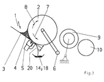
- the existing ink metering elements 5 can also serve as the ink wiper blade 11, in which case a guide foil 20 is assigned to them to discharge the ink into the ink reservoir 14 (FIG. 3).
- the doctor roller 2 is rotated counter to the printing mode of rotation 7 with the ink gap s open in the emptying operating direction 8, the residual ink located in the wedge ink fountain 1 is conveyed out of the wedge ink fountain and thus the wedge ink fountain emptied.
- the ink conveyed out of the wedge ink fountain 1 is peeled off from the inking doctor blade 11 by the duct roller 2 and passed into the ink reservoir 14.
- the ink reservoir 14 including the ink doctor blade 11 can be removed after this process.
- the color gap is closed the duct roller 2 rotated in the emptying direction 8, the color from the wedge ink fountain 1 promoted and doctored by the ink metering elements 5 from the duct roller and via the guide film 20 arranged on the ink metering elements 5 into the one designed as a trough 18 Color reservoir headed.
Landscapes
- Inking, Control Or Cleaning Of Printing Machines (AREA)
Abstract
Description
Nachteilig ist der hohe Aufwand für die Einsätze beim Wechsel der Farbe.
Nachfolgend werden die erfinderischen Lösungen an einem Ausführungsbeispiel näher erläutert.
- Fig. 1
- Keilfarbkasten mit flach eingestellten Farbabstreifrakel
- Fig. 2
- Keilfarbkasten mit steil angestellten Farbabstreifrakel
- Fig. 3
- Keilfarbkasten mit als Farbdosierelement ausgebildetem Farbabstreifrakel.
Die Druckbetriebs-Drehrichtung 7, d.h. die Drehrichtung, mit der die Duktorwalze im Druckbetrieb angetrieben wird, ist in Fig. 1 mit einem Pfeil gekennzeichnet Die Entleerungsbetriebs-Drehrichtung, d.h. die Drehrichtung, mit der die Duktorwalze im Entleerungsbetrieb rotiert, ist mit einem Doppelpfeil 8 gekennzeichnet.
Der Duktorwalze 2 ist im Farbheber 9 nachgeordnet, welcher zwischen der Duktorwalze und einer ersten Walze 10, des nicht dargestellten Farbwerkes pendelt.
Der Duktorwalze 2 ist ein Farbabstreifrakel 11 zugeordnet Dieses Farbabstreifrakel 11 ist unter einem negativen Winkel α bezogen auf eine Horizontale 12, d.h. flach angestellt, angeordnet. An der hinteren Kante des Farbabstreifrakels 11 ist eine Begrenzung 13 angeordnet welche mit dem Farbabstreifrakel 11 ein Farbreservoir 14 bildet.
Das Farbabstreifrakel 11 ist steil an die Duktorwalze 2 angestellt, d.h. unter einem kleinen Winkel β gegenüber einer Vertikalen 15. Der Rakelkante 16 des Farbabstreifrakels 11 ist ein Ableitblech 17 zugeordnet welches zum als Trog 18 ausgebildeten Farbreservoirs 14 führt.
Als Farbabstreifrakel 11 können auch die vorhandenen Farbdosierelemente 5 dienen, wobei in diesem Fall denselben eine Leitfolie 20 zur Ableitung der Farbe in das Farbreservoir 14 zugeordnet ist (Fig. 3).
Die aus dem Keilfarbkasten 1 geförderte Farbe wird von dem Farbabstreifrakel 11 von der Duktorwalze 2 abgeschält und in das Farbreservoir 14 geleitet. Das Farbreservoir 14 einschließlich Farbabstreifrakel 11 kann nach diesem Prozess entfernt werden.
Zur Vorsäuberung der Duktorwalze 2 wird dieselbe vor Beginn des Entleerungsprozesses bei geschlossenem Farbspalt s in Druckbetriebs-Drehrichtung 7 gedreht.
- 1
- Keilfarbkasten
- 2
- Duktorwalze
- 3
- Farbmesser
- 4
- Farbe
- 5
- Farbdosierelement
- 6
- Eigenantrieb
- 7
- Druckbetriebs-Drehrichtung
- 8
- Entleerungsbetriebs-Drehrichtung
- 9
- Farbheber
- 10
- Walze
- 11
- Farbabstreifrakel
- 12
- Horizontale
- 13
- Begrenzung
- 14
- Farbreservoir
- 15
- Vertikale
- 16
- Rakelkante
- 17
- Abteilblech
- 18
- Trog
- 19
- Folie
- 20
- Leitfolie
- s
- Spalt
- α
- negativer Winkel
- β
- Winkel
Claims (11)
- Verfahren zur Entleerung eines Keilfarbkastens in Druckmaschinen, wobei dem Keilfarbkasten eine Duktorwalze mit einem Eigenantrieb und Farbdosierelemente zur Einstellung eines Farbspaltes zwischen Duktorwalze und Keilfarbkasten zugeordnet sind, dadurch gekennzeichnet, dass die Duktorwalze bei geöffnetem Farbspalt entgegen der Druckbetriebs-Drehrichtung in Entleerungsbetriebs-Drehrichtung gedreht, die Farbe aus dem Keilfarbkasten gefördert, die geförderte Farbe von einem an die Duktorwalze angestellten Farbabstreifrakel abgeschält und einem Farbreservoir zugeführt wird.
- Verfahren zur Entleerung eines Keilfarbkastens in Druckmaschinen, wobei dem Keilfarbkasten eine Duktorwalze mit einem Eigenantrieb und Farbdosierelemente zur Einstellung eines Farbspaltes zwischen Duktorwalze und Keilfarbkasten zugeordnet sind, dadurch gekennzeichnet, dass die Duktorwalze bei geschlossenem Farbspalt entgegen der Druckbetriebs-Drehrichtung in Endeerungsbetriebs-Drehrichtung gedreht, die Farbe aus dem Keilfarbkasten gefördert, die geförderte Farbe von den an die Duktorwalze angestellten Farbdosierelementen abgeschält und einem Farbreservoir zugeführt wird.
- Verfahren zur Entleerung eines Keilfarbkastens nach Anspruch 1, dadurch gekennzeichnet, dass zur Duktorsäuberung vor Beginn des Farbförderprozesses die Duktorwalze bei geschlossenem Farbspalt in Druckbetriebs-Drehrichtung gedreht wird.
- Verfahren zur Entleerung eines Keilfarbkastens nach Anspruch 1 oder 2, dadurch gekennzeichnet, dass das Farbreservoir einschließlich Farbabstreifrakel nach dem Farbförderprozess entfernt wird.
- Einrichtung zur Entleerung eines Keilfarbkastens in Druckmaschinen mit einer dem Keilfarbkasten zugeordneten Duktorwalze einschließlich Eigenantrieb und Farbdosierelementen zur Einstellung eines Farbspaltes zwischen Duktorwalze und Keilfarbkasten, dadurch gekennzeichnet, dass der Duktorwalze (2) ein drehrichtungsumsteuerbarer Eigenantrieb (6) und entgegen der Druckbetriebs-Drehrichtung (7) gesehen nach dem Farbkeil des Keilfarbkastens (1) eine Farbabstreifrakel (11) mit Farbreservoir (14) zugeordnet ist.
- Einrichtung zur Entleerung eines Keilfarbkastens nach Anspruch 5, dadurch gekennzeichnet dass das mit einer an der hinteren Kante angeordneten Begrenzung (13) versehene Farbabstreifrakel (11) bezogen auf eine Horizontale (12) unter einem negativen Winkel (α), das Farbreservoir (14) bildend, angeordnet ist.
- Einrichtung zur Entleerung eines Keilfarbkastens nach Anspruch 5, dadurch gekennzeichnet, dass das Farbabstreifrakel (1) unter einem kleinen Winkel β gegenüber einer Vertikalen (15) an die Duktorwalze angestellt und im Bereich der Rakelkante (16) der Farbabstreifrakel (11) ein in das Farbreservoir (14) führendes Ableitblech (17) angeordnet ist.
- Einrichtung zur Entleerung eines Keilfarbkastens nach Anspruch 5 , dadurch gekennzeichnet dass die Länge des Farbabstreifrakels (11) der Duktorwalzenlänge entspricht.
- Einrichtung zur Entleerung eines Keilfarbkastens nach Anspruch 5, dadurch gekennzeichnet, dass die Länge des Farbabstreifrakels (11) kleiner als die Duktorwalzenlänge und das Farbabstreifrakel traversierend angeordnet ist.
- Einrichtung zur Entleerung eines Keilfarbkastens nach Anspruch 9, dadurch gekennzeichnet dass das Farbabstreifrakel (11) an einer traversierenden Farbrühreinrichtung angeordnet ist.
- Einrichtung zur Entleerung eines Keilfarbkastens nach Anspruch 9, dadurch gekennzeichnet dass das Farbmesser (3) mit einer bei Farbwechsel entfembaren Folie (19) belegt ist.
Applications Claiming Priority (2)
| Application Number | Priority Date | Filing Date | Title |
|---|---|---|---|
| DE19841129A DE19841129C2 (de) | 1998-09-09 | 1998-09-09 | Verfahren und Einrichtung zur Entleerung eines Keilfarbkastens |
| DE19841129 | 1998-09-09 |
Publications (3)
| Publication Number | Publication Date |
|---|---|
| EP0985529A2 true EP0985529A2 (de) | 2000-03-15 |
| EP0985529A3 EP0985529A3 (de) | 2000-06-28 |
| EP0985529B1 EP0985529B1 (de) | 2003-05-02 |
Family
ID=7880321
Family Applications (1)
| Application Number | Title | Priority Date | Filing Date |
|---|---|---|---|
| EP99115128A Expired - Lifetime EP0985529B1 (de) | 1998-09-09 | 1999-08-10 | Verfahren und Einrichtung zur Entleerung eines Keilfarbkastens |
Country Status (2)
| Country | Link |
|---|---|
| EP (1) | EP0985529B1 (de) |
| DE (2) | DE19841129C2 (de) |
Families Citing this family (2)
| Publication number | Priority date | Publication date | Assignee | Title |
|---|---|---|---|---|
| DE102005022954B4 (de) * | 2005-05-19 | 2008-05-15 | Koenig & Bauer Aktiengesellschaft | Verfahren und Vorrichtung zum Entleeren von Farbe aus dem Farbkasten eines Farbwerks einer Druckmaschine |
| DE102022100518A1 (de) | 2022-01-11 | 2023-07-13 | Koenig & Bauer Ag | Verfahren zur Reinigung eines Farbwerkes und Farbwerk |
Family Cites Families (10)
| Publication number | Priority date | Publication date | Assignee | Title |
|---|---|---|---|---|
| DE2619189A1 (de) * | 1976-04-30 | 1977-11-17 | Rotobind Ltd | Druckmaschine zur herstellung von flexodrucken |
| JPS562173A (en) * | 1979-06-20 | 1981-01-10 | Hitachi Seiko Ltd | Inking apparatus for use in light printer |
| DE2951649C2 (de) * | 1979-12-21 | 1982-11-18 | M.A.N.- Roland Druckmaschinen AG, 6050 Offenbach | Farbkasten von Druckmaschinen |
| DE3442662A1 (de) * | 1984-11-23 | 1986-06-05 | Albert-Frankenthal Ag, 6710 Frankenthal | Farbwerk |
| US5165342A (en) * | 1991-08-02 | 1992-11-24 | The Langston Corporation | Evacuation system for inking chamber |
| US5265535A (en) * | 1991-12-28 | 1993-11-30 | Kabushiki Kaisha Isowa | Printing machine for corrugated board sheet |
| DE9211572U1 (de) * | 1992-07-27 | 1993-01-07 | Koenig & Bauer AG, 8700 Würzburg | Einrichtung und Rakel zum Entleeren von Farbkästen für Rotationsdruckmaschinen |
| DE4315595C2 (de) * | 1993-05-11 | 1995-02-16 | Roland Man Druckmasch | Einsatz für Keilfarbkästen von Druckmaschinen |
| CA2128377C (en) * | 1993-07-20 | 2004-09-14 | Masayuki Izume | Inking arrangement for printing presses |
| DE19617746B4 (de) * | 1996-05-03 | 2005-05-25 | Heidelberger Druckmaschinen Ag | Farbwerk für eine Druckmaschine |
-
1998
- 1998-09-09 DE DE19841129A patent/DE19841129C2/de not_active Expired - Fee Related
-
1999
- 1999-08-10 EP EP99115128A patent/EP0985529B1/de not_active Expired - Lifetime
- 1999-08-10 DE DE59905294T patent/DE59905294D1/de not_active Expired - Lifetime
Also Published As
| Publication number | Publication date |
|---|---|
| EP0985529B1 (de) | 2003-05-02 |
| EP0985529A3 (de) | 2000-06-28 |
| DE19841129C2 (de) | 2003-07-31 |
| DE59905294D1 (de) | 2003-06-05 |
| DE19841129A1 (de) | 2000-03-16 |
Similar Documents
| Publication | Publication Date | Title |
|---|---|---|
| DE19624536C5 (de) | Abstreichmesser und Farbabführvorrichtung für Druckmaschinen | |
| DE10000903A1 (de) | Verfahren zum Betrieb einer Druckmaschine und Druckmaschine zur Durchführung des Verfahrens | |
| DE2703424C2 (de) | Farbwerk für Offset-Druckmaschinen | |
| DE4121017A1 (de) | Wascheinrichtung fuer farbwerke bei druckmaschinen | |
| DE69803630T2 (de) | Multifunktionales farbwerk für eine flexodruckmaschine | |
| EP0584523B1 (de) | Verfahren und Einrichtung zum Entleeren von Farbkästen für Rotationsdruckmaschinen | |
| EP1441908B1 (de) | Druckmaschinenwalzen-reinigungsverfahren und -vorrichtung | |
| EP0692381B1 (de) | Vorrichtung zum Entfernen von Farbe aus einem Farbwerk | |
| DE19841129C2 (de) | Verfahren und Einrichtung zur Entleerung eines Keilfarbkastens | |
| DE4012618A1 (de) | Rakelfarbwerk | |
| DE3413943A1 (de) | Bogenauslagevorrichtung, insbesondere fuer kleinoffsetmaschinen | |
| EP1090756B1 (de) | Farbkammerrakel | |
| DE4126722C2 (de) | ||
| DE102007010528B4 (de) | Druckmaschine und Verfahren zu deren Betrieb | |
| DD274003A1 (de) | Rakeleinrichtung fuer offsetdruckmaschinen | |
| DE19801623B4 (de) | Verfahren zum Betrieb einer Offset-Rotationsdruckmaschine | |
| DE102008032393A1 (de) | Fortdruckbeginn bei reduziertem Feuchtmittelauftrag | |
| DE102022100518A1 (de) | Verfahren zur Reinigung eines Farbwerkes und Farbwerk | |
| DE29820075U1 (de) | Farbversorgung für ein Farbwerk | |
| DE69723742T2 (de) | Farbrakel | |
| DE102012012089A1 (de) | Verfahren zum Betreiben eines Anilox-Druckwerksund Druckmaschine mit einem Anilox-Druckwerk | |
| DE102006025577B3 (de) | Wischvorrichtung einer Stichtiefdruckmaschine | |
| EP1132211B1 (de) | Reinigungsvorrichtung für eine Rotationsdruckmaschine | |
| DE102006029883A1 (de) | Vorrichtung zum Einfärben einer Walze an einer Rotationsdruckmaschine | |
| DE20308645U1 (de) | Reinigungsvorrichtung für das Druckwerk einer Rotationsdruckmaschine |
Legal Events
| Date | Code | Title | Description |
|---|---|---|---|
| PUAI | Public reference made under article 153(3) epc to a published international application that has entered the european phase |
Free format text: ORIGINAL CODE: 0009012 |
|
| AK | Designated contracting states |
Kind code of ref document: A2 Designated state(s): DE FR GB IT |
|
| AX | Request for extension of the european patent |
Free format text: AL;LT;LV;MK;RO;SI |
|
| PUAL | Search report despatched |
Free format text: ORIGINAL CODE: 0009013 |
|
| AK | Designated contracting states |
Kind code of ref document: A3 Designated state(s): AT BE CH CY DE DK ES FI FR GB GR IE IT LI LU MC NL PT SE |
|
| AX | Request for extension of the european patent |
Free format text: AL;LT;LV;MK;RO;SI |
|
| 17P | Request for examination filed |
Effective date: 20000608 |
|
| AKX | Designation fees paid |
Free format text: DE FR GB IT |
|
| 17Q | First examination report despatched |
Effective date: 20010312 |
|
| GRAH | Despatch of communication of intention to grant a patent |
Free format text: ORIGINAL CODE: EPIDOS IGRA |
|
| GRAH | Despatch of communication of intention to grant a patent |
Free format text: ORIGINAL CODE: EPIDOS IGRA |
|
| GRAA | (expected) grant |
Free format text: ORIGINAL CODE: 0009210 |
|
| AK | Designated contracting states |
Designated state(s): DE FR GB IT |
|
| REG | Reference to a national code |
Ref country code: GB Ref legal event code: FG4D Free format text: NOT ENGLISH |
|
| REF | Corresponds to: |
Ref document number: 59905294 Country of ref document: DE Date of ref document: 20030605 Kind code of ref document: P |
|
| GBT | Gb: translation of ep patent filed (gb section 77(6)(a)/1977) | ||
| ET | Fr: translation filed | ||
| PLBE | No opposition filed within time limit |
Free format text: ORIGINAL CODE: 0009261 |
|
| STAA | Information on the status of an ep patent application or granted ep patent |
Free format text: STATUS: NO OPPOSITION FILED WITHIN TIME LIMIT |
|
| 26N | No opposition filed |
Effective date: 20040203 |
|
| PGFP | Annual fee paid to national office [announced via postgrant information from national office to epo] |
Ref country code: GB Payment date: 20090827 Year of fee payment: 11 Ref country code: DE Payment date: 20090821 Year of fee payment: 11 |
|
| PGFP | Annual fee paid to national office [announced via postgrant information from national office to epo] |
Ref country code: IT Payment date: 20090821 Year of fee payment: 11 |
|
| GBPC | Gb: european patent ceased through non-payment of renewal fee |
Effective date: 20100810 |
|
| REG | Reference to a national code |
Ref country code: FR Ref legal event code: ST Effective date: 20110502 |
|
| PG25 | Lapsed in a contracting state [announced via postgrant information from national office to epo] |
Ref country code: IT Free format text: LAPSE BECAUSE OF NON-PAYMENT OF DUE FEES Effective date: 20100810 |
|
| REG | Reference to a national code |
Ref country code: DE Ref legal event code: R119 Ref document number: 59905294 Country of ref document: DE Effective date: 20110301 |
|
| PG25 | Lapsed in a contracting state [announced via postgrant information from national office to epo] |
Ref country code: FR Free format text: LAPSE BECAUSE OF NON-PAYMENT OF DUE FEES Effective date: 20100831 Ref country code: DE Free format text: LAPSE BECAUSE OF NON-PAYMENT OF DUE FEES Effective date: 20110301 |
|
| PG25 | Lapsed in a contracting state [announced via postgrant information from national office to epo] |
Ref country code: GB Free format text: LAPSE BECAUSE OF NON-PAYMENT OF DUE FEES Effective date: 20100810 |
|
| PGFP | Annual fee paid to national office [announced via postgrant information from national office to epo] |
Ref country code: FR Payment date: 20090914 Year of fee payment: 11 |