EP0982938B1 - Electronic camera - Google Patents
Electronic camera Download PDFInfo
- Publication number
- EP0982938B1 EP0982938B1 EP99306838A EP99306838A EP0982938B1 EP 0982938 B1 EP0982938 B1 EP 0982938B1 EP 99306838 A EP99306838 A EP 99306838A EP 99306838 A EP99306838 A EP 99306838A EP 0982938 B1 EP0982938 B1 EP 0982938B1
- Authority
- EP
- European Patent Office
- Prior art keywords
- exposure
- flash light
- image
- light emission
- electronic camera
- Prior art date
- Legal status (The legal status is an assumption and is not a legal conclusion. Google has not performed a legal analysis and makes no representation as to the accuracy of the status listed.)
- Expired - Lifetime
Links
- 238000012546 transfer Methods 0.000 claims description 16
- 239000007787 solid Substances 0.000 claims description 12
- 230000005284 excitation Effects 0.000 claims 1
- 229910052724 xenon Inorganic materials 0.000 description 22
- FHNFHKCVQCLJFQ-UHFFFAOYSA-N xenon atom Chemical compound [Xe] FHNFHKCVQCLJFQ-UHFFFAOYSA-N 0.000 description 22
- 238000010586 diagram Methods 0.000 description 10
- 230000015654 memory Effects 0.000 description 10
- 238000001514 detection method Methods 0.000 description 9
- 238000012545 processing Methods 0.000 description 9
- 230000007246 mechanism Effects 0.000 description 8
- 230000004044 response Effects 0.000 description 3
- 238000004804 winding Methods 0.000 description 3
- 239000004065 semiconductor Substances 0.000 description 2
- 230000003247 decreasing effect Effects 0.000 description 1
- 230000006870 function Effects 0.000 description 1
- 230000000977 initiatory effect Effects 0.000 description 1
- 239000004973 liquid crystal related substance Substances 0.000 description 1
- 238000005259 measurement Methods 0.000 description 1
- 238000000034 method Methods 0.000 description 1
- 238000012986 modification Methods 0.000 description 1
- 230000004048 modification Effects 0.000 description 1
- 230000003287 optical effect Effects 0.000 description 1
- 230000008569 process Effects 0.000 description 1
- 238000005070 sampling Methods 0.000 description 1
- 229920006395 saturated elastomer Polymers 0.000 description 1
- 230000002194 synthesizing effect Effects 0.000 description 1
- 230000003936 working memory Effects 0.000 description 1
Images


Classifications
-
- H—ELECTRICITY
- H04—ELECTRIC COMMUNICATION TECHNIQUE
- H04N—PICTORIAL COMMUNICATION, e.g. TELEVISION
- H04N23/00—Cameras or camera modules comprising electronic image sensors; Control thereof
- H04N23/70—Circuitry for compensating brightness variation in the scene
-
- H—ELECTRICITY
- H04—ELECTRIC COMMUNICATION TECHNIQUE
- H04N—PICTORIAL COMMUNICATION, e.g. TELEVISION
- H04N23/00—Cameras or camera modules comprising electronic image sensors; Control thereof
- H04N23/70—Circuitry for compensating brightness variation in the scene
- H04N23/74—Circuitry for compensating brightness variation in the scene by influencing the scene brightness using illuminating means
Definitions
- the present invention relates to an electronic camera for producing an image having a wide dynamic range by composing or synthesizing two image signals obtained by picking-up an object two times with a desired exposure amount ratio with the aid of a single solid state image sensing element, and more particularly to an electronic camera for producing a composed image having a wide dynamic range as well as a high quality by utilizing a flash light emitting device, e.g. stroboscopic flash device.
- a flash light emitting device e.g. stroboscopic flash device.
- Such an electronic camera is generally called a filmless digital still camera.
- a solid state image sensing element such as CCD image sensing element. It is well known that such a solid state image sensing element is liable to be saturated with a relatively low luminance and has a low S/N for a lower luminance. Therefore, there is a problem that a dynamic range of the solid state image sensing element is much narrower than a conventional photographic film.
- an electronic camera in which an image having an extended dynamic range is obtained by composing two image signals which are produced by a single solid state image sensing element when an object is picked-up with different exposure amounts two times successively.
- an electronic camera in which immediately after transferring signal charges stored in a light receiving section of a solid state image sensing element during a first exposure into a transfer section of the element, a second exposure having a longer exposure time than the first exposure is initiated, and signal charges stored in the light receiving section during the second exposure are transferred into the transfer section after the signal charges of the first exposure have been outputted from the solid state image sensing element.
- the second exposure can be performed for a time interval during which the signal charges produced by the first exposure and transferred into the vertical transfer section are read out of the solid state image sensing element, and therefore it is possible to obtain two image signals with a short time interval. Then, the thus obtained two image signals are composed to derive a composed image having a wider dynamic range.
- a camera is also known from EP-A-0387817 and EP-A-0836319.
- JP-A-108678 there is disclosed an electronic camera, in which upon producing an image with a wide dynamic range by composing two image signals obtained with different exposure amounts, one of the image signals is obtained by picking-up an object under the natural light, and the other image signal is obtained by picking-up the same object with a stroboscopic flash light, and these image signals are compared with each other to extract image portions having a larger amplitude to obtain a composed image.
- a similar system is disclosed in EP-A-0387817.
- the stroboscopic flash light when used, a portion of an object which is irradiated with the stroboscopic flash light can be picked-up such that the image signal with the stroboscopic flash light can have the given exposure amount ration with respect to the image signal with the natural light, but at a portion of the object which is not irradiated with the stroboscopic flash light, only the image signal with a same exposure amount as that with the natural light is obtained by the second exposure, and therefore there is a problem that the image picking-up operations could not be conducted with a desired exposure amount ratio between the first and second shots. Moreover, since a white balance of the image signal with the natural light differs from that with the stroboscopic flash light, when the image signals are composed, a color balance might be partially lost.
- stroboscopic flash devices each comprising a Xenon tube, a trigger capacitance and a light emission capacitance
- these stroboscopic flash devices are alternately used for the first and second exposures.
- the electronic camera including such a system is liable to be high in cost, large in size and heavy in weight. Therefore, it is desired that the two image picking-up operations are performed by means of a single stroboscopic flash device as used in a conventional camera in which no image signal composition is carried out.
- the stroboscopic flash device when operated for the two exposures like as the conventional stroboscopic flash exposure, i.e. when the trigger capacitance is charged and a trigger voltage is applied to the Xenon tube each time the stroboscopic flash exposure is carried out, two image signals could not be obtained with a short time interval.
- the trigger capacitance is charged through a resistor, and therefore a relatively long time period such as 6 msec is required for the trigger capacitance due to a time constant of the triggering circuit until the trigger capacitance is charged up to an effective trigger voltage. This results in that the second exposure could not be initiated immediately after the completion of the first exposure.
- the trigger voltage having an amplitude of several KVs might produce undesired noise, and if this second triggering period overlaps with the storing period or transferring period of the signal charges of the first exposure, the image signal obtained with the first exposure might be deteriorated.
- an electronic camera for producing an image having a wide dynamic range by composing two image signals obtained by picking-up an object twice with successive first and second exposures of respectively different first and second exposure amounts, comprising: an image picking-up means including a solid-state image sensing element for picking up an object to derive an image signal for each of said two exposures; a flash light emitting means comprising:
- said flash light emitting means is constituted by a conventional stroboscopic flash device including a discharge tube such as a Xenon tube, and the discharge tube is kept in the excited condition from the start of the first exposure to the end of the second exposure. Therefore, it is no longer necessary to recharge a trigger capacitance between the first exposure and the second exposure, and thus the two exposures can be carried out with the desired exposure amount ratio, while a time interval between the first exposure and the second exposure can be shortened. Therefore, even if the object includes a moving subject, it is always possible to obtain a composed image having a high quality.
- said image picking-up means is constructed such that electrostatic charges stored in a light receiving section of the solid state image sensing element during the first exposure are transferred into a vertical transfer section of the solid state image sensing element during the time interval between the first exposure and the second exposure during which the excited light emission is stopped.
- the first image signal is no more affected by the excited light emission for the second exposure, and therefore it is possible to attain an image signal having a high S/N, and the time interval during which the excited light emission is interrupted is further shortened.
- said flash light emission controlling means includes an exposure control table which represents a plurality of exposure control data values for the first exposure and a plurality of exposure control data values for the second exposure, said exposure control data values determining excited light emission times for the first and second exposures in accordance with said desired exposure amount ratio, and the excited light emission is controlled by selecting, from said exposure control table, exposure control data values corresponding to an image picking-up condition.
- said flash light emitting means comprises a flash light source, a trigger capacitance for driving said flash light source into an excited condition, and an light emission capacitance for supplying a light emitting energy to said flash light source in the excited condition to emit an excited light.
- the exposure control data values for the first exposure in said exposure control table of said flash light emission controlling means are determined on the basis of a reference voltage of said light emission capacitance, and the exposure control data values for the second exposure are determined on the basis of a voltage across said light emission capacitance which is determined by considering a voltage drop due the excited light emission for the first exposure.
- said plurality of exposure control data values of the first and second exposures may be constructed by exposure control data values for a conventional single exposure in which no image composition is carried out.
- a memory for storing the exposure control data values can have a smaller capacity, and the whole camera can be cheap in cost.
- said flash light emission controlling means includes a voltage detecting means for detecting a voltage across said light emission capacitance, and the excited light emission is controlled by selecting, from said exposure control table, an exposure control data value for the first exposure and an exposure control data value for the second exposure suitable for an exposure condition on the basis of a comparison of the detected voltage with the reference voltage.
- a voltage detecting means for detecting a voltage across said light emission capacitance
- the excited light emission is controlled by selecting, from said exposure control table, an exposure control data value for the first exposure and an exposure control data value for the second exposure suitable for an exposure condition on the basis of a comparison of the detected voltage with the reference voltage.
- said image picking-up means includes a variable stop which is controlled in accordance with a distance from the camera to the object, and exposure control data values for the first and second exposure control data values are selected from said exposure control table on the basis of a figure of the variable stop, i.e. stop value.
- the stop value may be increased to extend a workable range to a shorter distance side, and the image pick-up with a short distance, i.e. close-up shot can be easily realized.
- said flash light emitting means is controlled by said flash light emission controlling means such that flat light is emitted from said flash light emitting means in each of said first and second exposures.
- the flash light emitting means is operated to emit the excited light in a pulsatory manner with a short time non-emission interval, and therefore exposure amounts can be controlled much more accurately and it is possible to attain the image having a much higher quality.
- the light emission interruption period between the first exposure and the second exposure according to the invention does not mean the very short time non-emission interval in such a pulsatory light emission, and both terms should not be confused.
- said exposure amount ratio between the first exposure and the second exposure may be previously determined or may be determined in accordance with an image pick-up condition.
- Fig. 1 is a block diagram showing a whole structure of a first embodiment of the electronic camera according to the invention.
- the electronic camera of the present embodiment comprises a single plate type color CCD image sensing element 1, on to which is projected an image of an object by means of a lens unit 2 and a stop-shutter mechanism 3.
- the optical image of the object is then photoelectrically converted into an image signal.
- the image signal is amplified by an amplifier 4 and is converted into a digital image signal by an A/D converter 5.
- the thus obtained digital image signal is supplied to a camera signal processing circuit 6 and is processed thereby as image data.
- the output signal of the A/D converter 5 is also supplied to an AF (Automatic Focus), AE (Automatic Exposure), AWB Automatic White Balance) detection circuit 7, in which an AF detection processing for deriving AF information for automatically controlling a focus condition, an AE processing for deriving AE information for automatically controlling an exposure, and an AWB processing for deriving AWB information for automatically controlling a white balance.
- the AF information, AE information and AWB information from the AF, AE, AWB detection circuit 7 are supplied to the lens unit 2, the stop-shutter mechanism 3 and the camera signal processing circuit 6, respectively through CPU 8.
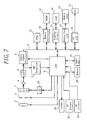
- the AF and AE functions performed by the AF, AE, AWB detection circuit 7 may be carried out by means of separate AF circuit 61 and AE circuit 62, respectively as shown in Fig. 7.
- the camera signal processing circuit 6 and CPU 8 are connected to a bus line 9, to which are also connected a DRAM 11 through a memory controller 10, said DRAM being used as a working memory upon processing color of the image data, and an image compressing circuit (JPEG) 12 for compressing the image data supplied from the camera signal processing circuit 6.
- a memory card I/F 14 for storing a compressed image signal data into a memory card 13, a liquid crystal display (LCD) 16 via a display circuit 15, and a PC I/F 18 for transferring the image data stored in the memory card 13 to a personal computer (PC) 17.
- Said LCD 16 displays an image stored in the memory card 13 and various image picking-up conditions.
- a stroboscopic flash device 19 To the CPU 8 are connected a stroboscopic flash device 19, a memory 20 storing an exposure control table denoting exposure control data values for controlling said stroboscopic flash device 19 in accordance with the AE information supplied from the AF, AE and AWB detection circuit 7 or the separate AF circuit 61 and AE circuit 62, and an input key 21 for setting various image pick-up modes and driving a trigger switch.
- the CCD image sensing element 1 is driven by a timing pulse from a timing generator (TG) 22 under the control of the CPU 8.
- Fig. 2 is a circuit diagram showing an embodiment of the stroboscopic flash device 19 shown in Fig. 1.
- the stroboscopic flash device 19 includes a booster circuit 31 having a primary side connected to a battery 33 via a main switch 32. Across a secondary side of the booster circuit 31, there is connected a parallel circuit consisting of a series circuit of light emission capacitance 34, resistor 35 and normally opened semiconductor switch 36 a series circuit of a discharge tube, in the present embodiment, a Xenon tube 37 and normally closed semiconductor switch 38. Across the switch 36, there is connected a primary winding of a trigger transformer 40 via a trigger capacitance. A secondary winding of the trigger transformer 40 has one end connected to a connecting point between the primary winding and the switch 36 and the other end connected to a triggering electrode of the Xenon tube 37.
- the light emission capacitance 34 is charged, and at the same time the trigger capacitance 39 is charged via the resistor 35.
- the switch 36 is closed for a short time period to discharge the trigger capacitance 39.
- a high voltage is applied to the triggering electrode 41 of the Xenon tube 37 to drive the Xenon tube into the excited condition.
- the light emission capacitance 34 is discharged through the Xenon tube 37 to emit excited light.
- a first exposure is performed.
- the switch 38 is temporarily opened by means of a light emission stop signal from the CPU 8.
- the excited light emission from the Xenon tube 37 is interrupted or stopped for a short time period, while the Xenon tube is kept still in the excited condition. Then, the switch 38 is closed and the excited light is emitted again from the Xenon tube 37 to conduct a second exposure.
- amounts of excited light emitted from the Xenon tube 37 during the first and second exposures are controlled in accordance with exposure control data stored in the memory 20 under the control of the CPU 8 such that an exposure amount of the second exposure corresponds to a correct exposure amount determined by the AE information or AF information supplied from the AF, AE, AWB detection circuit 7 or the separate AF circuit 61 or AE circuit 62, and an exposure amount of the first exposure is smaller than that of the second exposure by an amount corresponding to the predetermined exposure amount ratio with respect to the exposure amount of the second exposure. That is to say, in the present embodiment, the exposure amount of the first exposure is determined on the basis of the exposure amount of the second exposure.
- SE Short Exposure
- LE Long Exposure
- Figs. 3A-3F are timing charts for explaining the operation of the first embodiment.
- Fig. 3A denotes a vertical synchronizing signal for controlling a transfer from the operation of the CCD image sensing element 1
- Fig. 3B an exposure condition including an operation of the stop-shutter mechanism 3
- Fig. 3C the light emission start signal for initiating the excited light emission from the Xenon tube 37 in the stroboscopic flash device 19
- Fig. 3D the light emission stop signal for temporarily opening the switch 38 during the time interval between the first exposure and the second exposure
- Fig. 3E the excited light emission from the Xenon tube 37 of the stroboscopic flash device 19
- Fig. 3A denotes a vertical synchronizing signal for controlling a transfer from the operation of the CCD image sensing element 1
- Fig. 3B an exposure condition including an operation of the stop-shutter mechanism 3
- Fig. 3C the light emission start signal for initiating the excited light emission from the Xenon tube 37 in
- the light emission start signal i.e. trigger signal (Fig. 3C) having a duration of, for instance 20 ⁇ sec is generated from the CPU 8 in response to a release signal from the input key 21, and the excited light is emitted from the Xenon tube 37 to perform the first exposure.
- the stop-shutter mechanism 3 is operated prior to the first exposure. That is to say, the mechanical shutter is opened prior to the first exposure.
- the CPU 8 when the exposure time determined by the exposure control data for the first exposure has elapsed, the CPU 8 generates the light emission stop signal (Fig. 3D) having a duration of, for instance, 15 ⁇ sec to stop the excited light emission from the Xenon tube 37 temporarily, while the Xenon tube is kept in the excited condition. During this interval, electrostatic charges stored in the light receiving section of the CCD image sensing element 1 are transferred into the vertical transfer section of the CCD image sensing element. This transfer requires only a very short time period such as 5 ⁇ sec. Therefore, the time interval during which the excited light emission is interrupted may be set to a value within a range from about 5 ⁇ sec to about 30 ⁇ sec.
- the switch 38 when the switch 38 is closed again at the end of the light emission stop signal, the Xenon tube 37 initiates again to emit the excited flash light to conduct the second exposure. After elapsing a given exposure time, the CPU 8 produces again the light emission stop signal and the switch 38 is opened to stop the excited light emission from the Xenon tube 37.
- the light emission start signal is generated at such a timing that the light emission stop signal for stopping the emission of the excited light between the first exposure and the second exposure is generated within a time interval of the vertical blanking period of the vertical synchronizing signal VD.
- the stop-shutter mechanism 3 is opened in response to the actuation of the main switch 32 and is closed in response to the end of the second exposure.
- the electrostatic charges stored in the light receiving section of the CCD image sensing element 1 during the first exposure and transferred into the vertical transfer section during time interval during which the light emission is temporarily stopped is read out of the element during a period V 1 and the electrostatic charges stored in the light receiving section of the CCD image sensing element 1 during the second exposure are read out of the CCD image sensing element during a period V 2 . Therefore, the stop-shutter mechanism 3 is kept closed at least at the end of the period V 2 .
- the SE image signal obtained from the CCD image sensing element 1 by the first exposure and the LE image signal obtained by the second exposure are converted into SE digital image signal and LE digital image signal, respectively by the A/D converter 5, and the thus converted SE and LE digital image signals are processed by the camera signal processing circuit 6 and are stored in the DRAM 11 as SE image data and LE image data, respectively.
- image data of higher luminance regions of the object is extracted from the SE image data and image data of lower luminance regions is derived from the LE image data, and the thus extracted image data combined in accordance with a given image composition process to produce composed image data.
- the composed image data is compressed by the compressing circuit 12 and the compressed image data is stored in the memory card 13.
- the exposure control table stored in the memory 20 contains exposure control data values such that exposure control values for the first exposure are determined on the basis of a reference voltage which corresponds to a full charged voltage of the light emission capacitance 34 and exposure values are determined on the basis of the voltage across the light emission capacitance 35 at the end of the first exposure. It should be noted that as explained above, in the present embodiment, an amount of light of the second exposure corresponds to a correct amount of light determined by the light measurement data.
- the following table 1 denotes an example of the exposure control table containing exposure control data values.
- second exposure amounts of successive steps differ from each other by 0.1 EV.
- the light emitting times for the first exposure are determined on the basis of the reference voltage which appears across the fully charged light emission capacitance 34, and the light emitting times for the second exposure are determined on the basis of the voltage appearing across the light emission capacitance 34 at the end of the first exposure.
- the light emission from the stroboscopic flash device 19 is controlled in accordance with light emitting times for the first and second exposures in the selected step.
- Table 1 exposure control table considering voltage drop due to first exposure step first exposure time second exposure time step first exposure time second exposure time 1 23 79 18 48 273 2 25 85 19 52 352 3 26 105 20 55 382 4 27 107 21 56 412 5 28 110 22 58 420 6 29 115 23 60 486 7 30 120 24 62 544 8 31 125 25 64 635 9 32 130 26 66 660 10 33 134 27 70 900 11 34 144 28 73 989 12 35 169 29 78 1318 13 37 174 30 82 2142 14 39 195 31 86 4095 15 42 201 32 89 4095 16 42 215 33 94 4095 17 45 229
- the conventional stroboscopic flash device 19 in which the discharge tube is excited to emit flash light, and the discharge tube is kept in the excited condition from the start of the first exposure to the end of the second exposure, and therefore it is no more necessary to recharge the trigger capacitance 39 between the first and second exposures.
- the second exposure can be performed immediately after the first exposure, the first and second exposures can be performed with the predetermined exposure amount ratio, while the time interval between the first and second exposures can be very short. In this manner, even if the object contains a moving subject, it is always possible to obtain the composed image having a high quality.
- the SE image signal obtained by the first exposure is not affected by the stroboscopic flash light emission for the second exposure and can have a good S/N, and the time interval between the first and second exposures can be further shortened.
- the exposure control table is composed in such a manner that the exposure control data values for the first exposure are determined on the basis of the reference voltage produced across the fully charged light emission capacitance 34 and the exposure control values for the second exposure are determined taking into account of the voltage drop due to the first exposure. Therefore, the first and second exposures can be conducted accurately with the predetermined exposure amount ratio and the image quality of the composed image can be further improved.
- an exposure control table stored in the memory 20 is formed by a conventional exposure control table containing exposure control values for a conventional image pick-up operation with stroboscopic flash, and this table is commonly utilized for controlling the exposure amounts for the first and second exposures.
- the exposure control table contains steps denoting exposure control values for various exposure amounts at a given stop value with a step of 0.1 EV.
- a step for the second exposure is selected such that a relevant exposure amount corresponding to a correct exposure amount calculated prior to the actual exposure, and a step whose exposure amount is smaller than said exposure amount for the second exposure by the predetermined value, for instance 3 EV is selected for the first exposure.
- the stroboscopic flash is controlled in accordance with light emitting times denoted by the thus selected steps.
- the capacity of the memory 20 can be small and the whole camera can be less expensive. It should be noted that in the second embodiment, since the exposure control table is formed on the basis of the reference voltage appearing across the fully charged light emission capacitance 34, there is an small error in the exposure amount for the first exposure, but there is a few cases in which said error might affect the image composition.
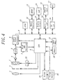
- Fig. 4 is a block diagram illustrating a third embodiment of the electronic camera according to the invention.
- a voltage detecting means 45 for detecting the voltage across the light emission capacitance 34. The detected voltage is compared in the CPU 8 with the reference voltage appearing across the fully charged light emission capacitance 34, and desired exposure control data values are selected from the table in accordance with a comparison result.
- Fig. 5 is a circuit diagram showing an embodiment of the voltage detecting means 45.
- the voltage detecting means 45 includes a series circuit of resistors 51 and 52 connected across the light emission capacitance 34, and a voltage detecting circuit 53 connected to a junction between these resistors.
- the voltage across the light emission capacitance 34 is divided by the voltage divider consisting of the resistors 51, 52 and the divided voltage is detected by the voltage detecting circuit 53.
- An analog signal representing the detected voltage value is converted by an A/D converter into digital data and the thus converted digital data is supplied to the
- an exposure amount of the stroboscopic flash is proportional to the charged voltage of the light emission capacitance 34. Therefore, a proportional constant is stored in the CPU 8, and a step in the exposure control table shifted from a step corresponding to a correct exposure amount in accordance with a comparison result between the voltage detected by the voltage detecting circuit 53 and the reference voltage is selected.
- the two image pick-up operations can be performed with the predetermined exposure amount ratio in accordance with much more accurate exposure control data values, and therefore the composed image having a higher quality can be obtained.
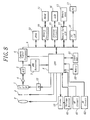
- the stop value of the stop-shutter mechanism 3 is controlled by means of the CPU 8 in accordance with an image picking-up condition determined by the AF information or AE information supplied from the AF, AE, AWB detection circuit 7 or separate AF circuit 61 or AE circuit 62 shown in Fig. 8.
- the memory 20 there are stored exposure control tables for respective stop values, and the first and second exposures are controlled in accordance with a step selected from a table corresponding to a stop value such that an exposure amount of the second exposure corresponds to a correct exposure amount determined by the AF information or AE information.
- the image signal (LE) obtained by the second exposure corresponds to the correct exposure amount determined by the AF information or AE information and the image signal (SE) is obtained by the first exposure whose exposure amount has the predetermined exposure amount ratio. Therefore, when the exposure control table which is formed under such a condition that the stop value is fixed, a distance range over which the image pick-up is possible is narrowed as compared with the conventional stroboscopic flash photography without the image composition.
- the stop value of the stop-shutter mechanism 3 is changed from F2.8 to F5.6, and a step is selected from an exposure control table corresponding to the stop value F5.6 in accordance with the AF information or AE information.
- the stop value When the stop value is changed in the manner explained above, the distance range toward the shorter distance can be widened and the image composition mode can be performed even in a close-up photography.
- an exposure amount of the first exposure and an exposure amount of the second exposure are determined in accordance with the predetermined exposure amount ratio.
- the exposure amount ratio between the first exposure and the second exposure is determined in accordance with the AF information or AE information supplied from the AF, AE, AWB detection circuit 7 or AF circuit 61 or AE circuit 62 shown in Fig. 8. Then, exposure control values for the first and second exposures are selected from the exposure control table stored in the memory 20 in accordance with the determined exposure amount ratio.
- the exposure amount ratio between the first and second exposures is fixed to, for instance 3 EV
- a usable distance range is narrowed by said exposure amount ratio as compared with the conventional stroboscopic flash photography, and the image picking-up could not be performed at such a short distance.
- the exposure amount ratio is changed to a smaller value such as 2 EV. Then, exposure control data values are selected from an exposure control table corresponding to the changed exposure amount ratio of 2 EV, and emission times of the stroboscopic flash for the first and second exposures are controlled in accordance with the selected exposure control data values.
- the exposure control table containing exposure control values calculated in accordance with the exposure amount ratio is used like as the first embodiment, a plurality of such tables each corresponding to respective exposure amount ratios are stored in the memory 20, At first, a desired table is selected from said plurality of tables in accordance with a desired exposure amount ratio, and then a desired step is selected from the selected table in accordance with the AF information or AE information.
- the stroboscopic flash emission can be controlled in accordance with exposure control data values contained in the selected step.
- a desired step corresponding to the AF information or AE information is first selected as the exposure control data value for the second exposure, and next a desired step which differs from said first exposure by an exposure amount ratio which is determined by the AF information is selected for the first exposure.
- the stroboscopic flash emission for the first and second exposures can be controlled in accordance with exposure control data values contained in the selected steps.
- a usable range for the shorter distance can be expanded, and like as the fourth embodiment, the image composition can be performed even for an object which is closer to the camera.
- the stroboscopic flash device 19 is operated such that the excited light is emitted continuously in each of the first and second exposures.
- the emission stop signal having a short repetition period is supplied from the CPU 8 to the switch 38 shown in Fig. 2 or Fig. 5 as depicted in Fig. 6D such that the stroboscopic flash is emitted repeatedly from the Xenon tube 27 of the stroboscopic flash device 19.
- Such a pulsatory light emission is generally called a flat emission.
- the Xenon tube 37 when the Xenon tube 37 is driven in the flat emission mode, an mount of light emitted during each of the first and second exposures can be controlled much more precisely. Therefore, the composed image can have a much higher quality.
- the present invention is not limited to the embodiments explained above, but many modifications and alternations may be conceived by a person skilled in the art within the scope of the invention.
- the light emitting times for the first and second exposures are controlled in accordance with exposure control data values in one or more exposure control tables, but the light emitting times for the first and second exposures may be calculated from the AE information as long as a linear relationship is existent between an amount of the excited emission light and the light emitting time.
- the first exposure is performed by emitting the flash light for a desired time period, the excited light emission is temporarily stopped at the end of the first exposure, and after a short time interval the excited light is again emitted to perform the second exposure for a desired time period. Since the light emitting means is kept in the excited condition even after the first exposure until the end of the second exposure, it is no more necessary to recharge the trigger capacitance prior to the second exposure, the time interval between the first exposure and the second exposure can be very short. Therefore, even if the object contains a moving subject, the composed image can have a very high quality.
- the composed image can have a very wide dynamic range.
- the image signal obtained by the first exposure can be read out without being affected by noise which might be produced during the excited light emission for the second exposure.
Landscapes
- Engineering & Computer Science (AREA)
- Multimedia (AREA)
- Signal Processing (AREA)
- Stroboscope Apparatuses (AREA)
- Studio Devices (AREA)
- Exposure Control For Cameras (AREA)
- Cameras In General (AREA)
Applications Claiming Priority (2)
| Application Number | Priority Date | Filing Date | Title |
|---|---|---|---|
| JP10243314A JP2000078462A (ja) | 1998-08-28 | 1998-08-28 | 電子カメラ |
| JP24331498 | 1998-08-28 |
Publications (2)
| Publication Number | Publication Date |
|---|---|
| EP0982938A1 EP0982938A1 (en) | 2000-03-01 |
| EP0982938B1 true EP0982938B1 (en) | 2007-04-11 |
Family
ID=17102001
Family Applications (1)
| Application Number | Title | Priority Date | Filing Date |
|---|---|---|---|
| EP99306838A Expired - Lifetime EP0982938B1 (en) | 1998-08-28 | 1999-08-27 | Electronic camera |
Country Status (4)
| Country | Link |
|---|---|
| US (1) | US6753920B1 (enExample) |
| EP (1) | EP0982938B1 (enExample) |
| JP (1) | JP2000078462A (enExample) |
| DE (1) | DE69935764T2 (enExample) |
Families Citing this family (33)
| Publication number | Priority date | Publication date | Assignee | Title |
|---|---|---|---|---|
| JPH1127575A (ja) * | 1997-06-30 | 1999-01-29 | Canon Inc | 撮像装置 |
| US6744471B1 (en) * | 1997-12-05 | 2004-06-01 | Olympus Optical Co., Ltd | Electronic camera that synthesizes two images taken under different exposures |
| JP3822393B2 (ja) * | 1999-08-10 | 2006-09-20 | 富士写真フイルム株式会社 | 撮像装置および撮像制御方法 |
| US7023479B2 (en) * | 2000-05-16 | 2006-04-04 | Canon Kabushiki Kaisha | Image input apparatus having addition and subtraction processing |
| DE10028240A1 (de) * | 2000-06-07 | 2001-12-13 | Bundesdruckerei Gmbh | Vorrichtung zur automatischen Auswertung von fluoreszierenden Echtheitsmerkmalen |
| DE10044746C5 (de) * | 2000-09-09 | 2004-02-19 | Basler Ag | Steuerung für ein elektronisches Gerät zum Empfang elektromagnetischer Wellen, insbesondere Licht |
| JP2002090864A (ja) * | 2000-09-12 | 2002-03-27 | Canon Inc | プリンタ付カメラ |
| US7050094B2 (en) * | 2000-10-26 | 2006-05-23 | Micron Technology, Inc. | Wide dynamic range operation for CMOS sensor with freeze-frame shutter |
| US7298402B2 (en) | 2000-10-26 | 2007-11-20 | Olympus Corporation | Image-pickup apparatus with expanded dynamic range capabilities |
| JP2002359774A (ja) * | 2001-03-30 | 2002-12-13 | Fuji Photo Film Co Ltd | 電子カメラ |
| JP2002298132A (ja) * | 2001-04-02 | 2002-10-11 | Fuji Mach Mfg Co Ltd | 撮像システム,撮像システム制御プログラムおよび電気部品装着システム |
| US20020191102A1 (en) * | 2001-05-31 | 2002-12-19 | Casio Computer Co., Ltd. | Light emitting device, camera with light emitting device, and image pickup method |
| FI111417B (fi) * | 2001-06-01 | 2003-07-15 | Nokia Corp | Digitaalikameran salamavalon ohjaus |
| JP4451583B2 (ja) * | 2001-12-27 | 2010-04-14 | 富士フイルム株式会社 | 撮像装置、撮像方法、及びプログラム |
| JP2003319255A (ja) * | 2002-02-20 | 2003-11-07 | Casio Comput Co Ltd | 閃光装置付撮像装置、閃光装置の制御方法及び撮像方法、並びに撮像装置制御プログラム |
| JP3680827B2 (ja) * | 2002-08-27 | 2005-08-10 | コニカミノルタフォトイメージング株式会社 | デジタルカメラ |
| KR100503040B1 (ko) * | 2002-12-14 | 2005-07-21 | 삼성테크윈 주식회사 | 한 번의 예비 발광이 수행되는 플레시 장치의 제어 방법 |
| JP2006033049A (ja) * | 2004-07-12 | 2006-02-02 | Konica Minolta Photo Imaging Inc | 撮像装置 |
| JP2006033749A (ja) * | 2004-07-21 | 2006-02-02 | Konica Minolta Photo Imaging Inc | 撮像装置 |
| JP4350616B2 (ja) | 2004-08-24 | 2009-10-21 | キヤノン株式会社 | 撮像装置及びその制御方法 |
| JP4604644B2 (ja) * | 2004-10-21 | 2011-01-05 | 株式会社ニコン | 撮影用照明装置およびカメラ |
| JP2007129751A (ja) * | 2006-12-18 | 2007-05-24 | Fujifilm Corp | 撮像装置、撮像方法、及びプログラム |
| CN101320194B (zh) * | 2007-06-07 | 2010-09-29 | 鸿富锦精密工业(深圳)有限公司 | 闪光灯控制系统及方法 |
| US20090059039A1 (en) * | 2007-08-31 | 2009-03-05 | Micron Technology, Inc. | Method and apparatus for combining multi-exposure image data |
| JP5138521B2 (ja) * | 2008-09-19 | 2013-02-06 | 富士フイルム株式会社 | 撮像装置及び撮像方法 |
| JP4934123B2 (ja) * | 2008-09-30 | 2012-05-16 | 富士フイルム株式会社 | 撮影装置および方法 |
| JP5858744B2 (ja) * | 2011-11-21 | 2016-02-10 | キヤノン株式会社 | 撮像装置及びカメラシステム |
| US9075566B2 (en) | 2012-03-02 | 2015-07-07 | Microsoft Technoogy Licensing, LLC | Flexible hinge spine |
| US9460029B2 (en) | 2012-03-02 | 2016-10-04 | Microsoft Technology Licensing, Llc | Pressure sensitive keys |
| US20130300590A1 (en) | 2012-05-14 | 2013-11-14 | Paul Henry Dietz | Audio Feedback |
| US8786767B2 (en) | 2012-11-02 | 2014-07-22 | Microsoft Corporation | Rapid synchronized lighting and shuttering |
| US10616463B2 (en) * | 2017-12-06 | 2020-04-07 | Rockwell Collins, Inc. | Synchronized camera and lighting system |
| CN108184075B (zh) * | 2018-01-17 | 2019-05-10 | 百度在线网络技术(北京)有限公司 | 用于生成图像的方法和装置 |
Family Cites Families (12)
| Publication number | Priority date | Publication date | Assignee | Title |
|---|---|---|---|---|
| US4647975A (en) * | 1985-10-30 | 1987-03-03 | Polaroid Corporation | Exposure control system for an electronic imaging camera having increased dynamic range |
| US5638118A (en) * | 1987-06-09 | 1997-06-10 | Canon Kabushiki Kaisha | Image sensing device with diverse storage times used in picture composition |
| EP0387817A3 (en) * | 1989-03-16 | 1991-12-11 | Konica Corporation | Electronic still camera |
| JP2938123B2 (ja) * | 1990-03-30 | 1999-08-23 | 株式会社東芝 | 多機能デジタルカメラ |
| JPH05191715A (ja) * | 1990-10-23 | 1993-07-30 | Ricoh Co Ltd | ストロボ制御方法 |
| JPH04207581A (ja) * | 1990-11-30 | 1992-07-29 | Canon Inc | 撮像装置 |
| EP0487332B1 (en) * | 1990-11-22 | 1997-10-08 | Canon Kabushiki Kaisha | Image pick up device |
| JP3627111B2 (ja) * | 1995-05-26 | 2005-03-09 | フジノン株式会社 | ストロボ内蔵カメラ |
| US6151073A (en) | 1996-03-28 | 2000-11-21 | Fotonation, Inc. | Intelligent camera flash system |
| US6278490B1 (en) * | 1996-05-23 | 2001-08-21 | Olympus Optical Co., Ltd. | Exposure control for an image pickup apparatus that uses an electronic flash |
| JP3203188B2 (ja) | 1996-09-03 | 2001-08-27 | 三洋電機株式会社 | 電子スチルカメラ |
| JPH10126663A (ja) | 1996-10-14 | 1998-05-15 | Ricoh Co Ltd | 画像入力装置及び画像入力システム |
-
1998
- 1998-08-28 JP JP10243314A patent/JP2000078462A/ja active Pending
-
1999
- 1999-08-27 US US09/384,414 patent/US6753920B1/en not_active Expired - Fee Related
- 1999-08-27 DE DE69935764T patent/DE69935764T2/de not_active Expired - Lifetime
- 1999-08-27 EP EP99306838A patent/EP0982938B1/en not_active Expired - Lifetime
Also Published As
| Publication number | Publication date |
|---|---|
| JP2000078462A (ja) | 2000-03-14 |
| US6753920B1 (en) | 2004-06-22 |
| EP0982938A1 (en) | 2000-03-01 |
| DE69935764D1 (de) | 2007-05-24 |
| DE69935764T2 (de) | 2007-12-27 |
Similar Documents
| Publication | Publication Date | Title |
|---|---|---|
| EP0982938B1 (en) | Electronic camera | |
| EP0280511B1 (en) | Still video camera | |
| JP3420405B2 (ja) | 撮像装置 | |
| US7064788B2 (en) | Electronic camera with repeating flash | |
| US8018498B2 (en) | Image pickup apparatus and exposure control method | |
| US7817910B2 (en) | Imaging apparatus | |
| JP2000111790A (ja) | オートフォーカス装置 | |
| EP0828383A2 (en) | Electronic camera and battery voltage controlling method employed therein | |
| US6864474B2 (en) | Focusing apparatus for adjusting focus of an optical instrument | |
| JP5196985B2 (ja) | カメラシステム及び撮像装置 | |
| US5019911A (en) | Image pickup apparatus with mode dependent light measurement | |
| US4901337A (en) | X-ray imaging apparatus | |
| US7801429B2 (en) | Image taking apparatus | |
| JP4000413B2 (ja) | 電子カメラ | |
| JP3957147B2 (ja) | 合焦装置 | |
| JP4412746B2 (ja) | 電子スチルカメラ | |
| US20070253694A1 (en) | Imaging apparatus | |
| JP4015260B2 (ja) | 電子カメラ | |
| JP2001313867A (ja) | デジタルカメラ | |
| JPH05167910A (ja) | 電子的撮像装置 | |
| JP2009055287A (ja) | 撮像装置及び撮像方法 | |
| JP3828822B2 (ja) | 撮像装置、画像処理システム、撮像方法、及びプログラム | |
| JP3135927B2 (ja) | 眼底カメラ | |
| JP3459519B2 (ja) | バッテリー残量検出装置 | |
| JP3123891B2 (ja) | 電子スチルカメラ |
Legal Events
| Date | Code | Title | Description |
|---|---|---|---|
| PUAI | Public reference made under article 153(3) epc to a published international application that has entered the european phase |
Free format text: ORIGINAL CODE: 0009012 |
|
| AK | Designated contracting states |
Kind code of ref document: A1 Designated state(s): DE |
|
| AX | Request for extension of the european patent |
Free format text: AL;LT;LV;MK;RO;SI |
|
| 17P | Request for examination filed |
Effective date: 20000419 |
|
| AKX | Designation fees paid |
Free format text: DE |
|
| RAP1 | Party data changed (applicant data changed or rights of an application transferred) |
Owner name: OLYMPUS CORPORATION |
|
| GRAP | Despatch of communication of intention to grant a patent |
Free format text: ORIGINAL CODE: EPIDOSNIGR1 |
|
| GRAS | Grant fee paid |
Free format text: ORIGINAL CODE: EPIDOSNIGR3 |
|
| GRAA | (expected) grant |
Free format text: ORIGINAL CODE: 0009210 |
|
| AK | Designated contracting states |
Kind code of ref document: B1 Designated state(s): DE |
|
| REF | Corresponds to: |
Ref document number: 69935764 Country of ref document: DE Date of ref document: 20070524 Kind code of ref document: P |
|
| PLBE | No opposition filed within time limit |
Free format text: ORIGINAL CODE: 0009261 |
|
| STAA | Information on the status of an ep patent application or granted ep patent |
Free format text: STATUS: NO OPPOSITION FILED WITHIN TIME LIMIT |
|
| 26N | No opposition filed |
Effective date: 20080114 |
|
| PGFP | Annual fee paid to national office [announced via postgrant information from national office to epo] |
Ref country code: DE Payment date: 20130821 Year of fee payment: 15 |
|
| REG | Reference to a national code |
Ref country code: DE Ref legal event code: R119 Ref document number: 69935764 Country of ref document: DE |
|
| REG | Reference to a national code |
Ref country code: DE Ref legal event code: R082 Ref document number: 69935764 Country of ref document: DE Representative=s name: HASELTINE LAKE LLP, DE |
|
| REG | Reference to a national code |
Ref country code: DE Ref legal event code: R119 Ref document number: 69935764 Country of ref document: DE Effective date: 20150303 |
|
| PG25 | Lapsed in a contracting state [announced via postgrant information from national office to epo] |
Ref country code: DE Free format text: LAPSE BECAUSE OF NON-PAYMENT OF DUE FEES Effective date: 20150303 |