EP0982536B1 - Ensemble d'éléments pour la formation de lampes - Google Patents
Ensemble d'éléments pour la formation de lampes Download PDFInfo
- Publication number
- EP0982536B1 EP0982536B1 EP99115681A EP99115681A EP0982536B1 EP 0982536 B1 EP0982536 B1 EP 0982536B1 EP 99115681 A EP99115681 A EP 99115681A EP 99115681 A EP99115681 A EP 99115681A EP 0982536 B1 EP0982536 B1 EP 0982536B1
- Authority
- EP
- European Patent Office
- Prior art keywords
- module
- kit according
- mounting
- bulb
- housing
- Prior art date
- Legal status (The legal status is an assumption and is not a legal conclusion. Google has not performed a legal analysis and makes no representation as to the accuracy of the status listed.)
- Expired - Lifetime
Links
Images


Classifications
-
- F—MECHANICAL ENGINEERING; LIGHTING; HEATING; WEAPONS; BLASTING
- F21—LIGHTING
- F21V—FUNCTIONAL FEATURES OR DETAILS OF LIGHTING DEVICES OR SYSTEMS THEREOF; STRUCTURAL COMBINATIONS OF LIGHTING DEVICES WITH OTHER ARTICLES, NOT OTHERWISE PROVIDED FOR
- F21V23/00—Arrangement of electric circuit elements in or on lighting devices
- F21V23/06—Arrangement of electric circuit elements in or on lighting devices the elements being coupling devices, e.g. connectors
-
- F—MECHANICAL ENGINEERING; LIGHTING; HEATING; WEAPONS; BLASTING
- F21—LIGHTING
- F21V—FUNCTIONAL FEATURES OR DETAILS OF LIGHTING DEVICES OR SYSTEMS THEREOF; STRUCTURAL COMBINATIONS OF LIGHTING DEVICES WITH OTHER ARTICLES, NOT OTHERWISE PROVIDED FOR
- F21V15/00—Protecting lighting devices from damage
- F21V15/01—Housings, e.g. material or assembling of housing parts
-
- F—MECHANICAL ENGINEERING; LIGHTING; HEATING; WEAPONS; BLASTING
- F21—LIGHTING
- F21V—FUNCTIONAL FEATURES OR DETAILS OF LIGHTING DEVICES OR SYSTEMS THEREOF; STRUCTURAL COMBINATIONS OF LIGHTING DEVICES WITH OTHER ARTICLES, NOT OTHERWISE PROVIDED FOR
- F21V17/00—Fastening of component parts of lighting devices, e.g. shades, globes, refractors, reflectors, filters, screens, grids or protective cages
- F21V17/10—Fastening of component parts of lighting devices, e.g. shades, globes, refractors, reflectors, filters, screens, grids or protective cages characterised by specific fastening means or way of fastening
- F21V17/12—Fastening of component parts of lighting devices, e.g. shades, globes, refractors, reflectors, filters, screens, grids or protective cages characterised by specific fastening means or way of fastening by screwing
-
- F—MECHANICAL ENGINEERING; LIGHTING; HEATING; WEAPONS; BLASTING
- F21—LIGHTING
- F21V—FUNCTIONAL FEATURES OR DETAILS OF LIGHTING DEVICES OR SYSTEMS THEREOF; STRUCTURAL COMBINATIONS OF LIGHTING DEVICES WITH OTHER ARTICLES, NOT OTHERWISE PROVIDED FOR
- F21V17/00—Fastening of component parts of lighting devices, e.g. shades, globes, refractors, reflectors, filters, screens, grids or protective cages
- F21V17/10—Fastening of component parts of lighting devices, e.g. shades, globes, refractors, reflectors, filters, screens, grids or protective cages characterised by specific fastening means or way of fastening
- F21V17/16—Fastening of component parts of lighting devices, e.g. shades, globes, refractors, reflectors, filters, screens, grids or protective cages characterised by specific fastening means or way of fastening by deformation of parts; Snap action mounting
- F21V17/164—Fastening of component parts of lighting devices, e.g. shades, globes, refractors, reflectors, filters, screens, grids or protective cages characterised by specific fastening means or way of fastening by deformation of parts; Snap action mounting the parts being subjected to bending, e.g. snap joints
-
- F—MECHANICAL ENGINEERING; LIGHTING; HEATING; WEAPONS; BLASTING
- F21—LIGHTING
- F21V—FUNCTIONAL FEATURES OR DETAILS OF LIGHTING DEVICES OR SYSTEMS THEREOF; STRUCTURAL COMBINATIONS OF LIGHTING DEVICES WITH OTHER ARTICLES, NOT OTHERWISE PROVIDED FOR
- F21V23/00—Arrangement of electric circuit elements in or on lighting devices
- F21V23/02—Arrangement of electric circuit elements in or on lighting devices the elements being transformers, impedances or power supply units, e.g. a transformer with a rectifier
-
- F—MECHANICAL ENGINEERING; LIGHTING; HEATING; WEAPONS; BLASTING
- F21—LIGHTING
- F21V—FUNCTIONAL FEATURES OR DETAILS OF LIGHTING DEVICES OR SYSTEMS THEREOF; STRUCTURAL COMBINATIONS OF LIGHTING DEVICES WITH OTHER ARTICLES, NOT OTHERWISE PROVIDED FOR
- F21V31/00—Gas-tight or water-tight arrangements
-
- F—MECHANICAL ENGINEERING; LIGHTING; HEATING; WEAPONS; BLASTING
- F21—LIGHTING
- F21Y—INDEXING SCHEME ASSOCIATED WITH SUBCLASSES F21K, F21L, F21S and F21V, RELATING TO THE FORM OR THE KIND OF THE LIGHT SOURCES OR OF THE COLOUR OF THE LIGHT EMITTED
- F21Y2103/00—Elongate light sources, e.g. fluorescent tubes
Definitions
- the present invention relates to a kit for lights, especially safety and escape sign lights.
- corresponding lamps have been constructed in practice, depending on the type of installation, such as wall, ceiling or pendulum mounting, from different components. It was used depending on the type of mounting a corresponding base plate, which was used both for fixing the lamp and for holding a corresponding lamp. With this base plate then appropriate housing had to be assembled from a variety of individual parts, with one side or two-sided in the housing illuminated by the lamp disk was used. On such a disk, for example, pictograms are applied, which point the way to the nearest emergency exit or the like. If the disc with the pictogram has a corresponding size as needed, so had the base plate in addition to the size of the appropriate size to be mounted.
- US-A-5,379,540 discloses a modular structure of a planar array illumination field, each module comprising a base portion, a lamp pan, and a disk array enclosure. The structure of each such module is fixed and the modules differ in size at most from each other.
- the present invention is therefore based on the object, starting from the known from practice lights to provide a kit for such lights by the lights in a quick and inexpensive way different light design and / or size can be produced.
- a kit for lights which is formed from at least one mounting module, a lamp module and a housing module.
- the mounting module is used to attach the lamp and has connectable with electrical leads terminals and their first associated plug contacts.
- the lamp module has sockets for holding and electrical supply of a lamp and second plug contacts on the lamp module and mounting module are detachably connected to each other, wherein at such a compound is simultaneously an electrical contacting of the first and second plug contacts.
- the kit has several housing modules.
- the respective housing module is characteristic of the respective lamp and with mounting module and / or lamp module connectable. In the housing module, a pane illuminated by the lamp is inserted in particular interchangeably.
- kits are at least components of the kit, wherein in other embodiments of the invention in addition to mounting module and lamp module and a plurality of housing modules or other modules can be used.
- all lamps that can be produced by the kit according to the invention are common mounting module and lamp module. These have always the same structure and are adaptable to different requirements for identifying, for example, an escape route through the different housing modules as different sized lights or through different panes in a housing module. If the mounting module is attached to a wall or ceiling or the like, provided at this attachment point electrical leads are connected to the terminals on the mounting module, which simultaneously takes place an electrical supply of the first plug contacts.
- the electrical supply of the lamp held by the sockets of the lamp module is effected by contacting the first and second plug contacts.
- a housing module or, as will be explained later, further modules can be detachably fastened to the mounting and / or lamp module.
- this has a substantially rectangular base plate, are formed in the mounting holes for mounting on a wall or ceiling. By means of the mounting hole and appropriate screws, the attachment to the wall or ceiling.
- spacers may protrude from a lamp module assigning the front of the base plate for abutment with a rear side of the lamp module. On this the lamp module is pressed with its back and then releasably attached to the mounting module.
- the spacers may be substantially cylindrical and have the lamp module open blind bore into which screws through holes in the lamp module can be screwed.
- the spacers may have at their free ends Ausrichtab arrangements that can be brought into abutment with a protruding from the back of the lamp module edge flange. Depending on the arrangement of the spacers can be done in this way an alignment of lamp and mounting module in the longitudinal and / or transverse direction.
- a circumferential sealing strip may be formed on the front of the base plate, which abuts sealingly attached to the mounting module at the lamp module. In this way, the entry of dust or water into the space between the mounting and lamp module is reliably prevented, so that ignition of an example, easily flammable gas is prevented by facilities of the lamp.
- latching or counter-locking elements can be formed on the mounting and lamp module, which can be brought into engagement with such a detachable connection of the modules.
- a simple embodiment of such a locking element on the mounting module may be an elastically deflectable, protruding from the front of the base plate latching hook.
- the lamp module can have a substantially rectangular holding plate, from the rear side of which the sealing wall protrudes and in which the latching openings are formed.
- holding plate and base plate may have substantially the same dimensions in the longitudinal and transverse directions.
- a front side of the retaining plate can be used to arrange the sockets.
- the sockets may be suitable for different types of lamps, with fluorescent tubes in particular being preferred.
- the second plug contacts and at least electrical supply lines to the sockets and to a releasably mounted on the backside electronic ballast are arranged. Further devices, for example, for remote monitoring of the lamp or the like can also be arranged on the lamp module on the front or back.
- the first and second plug contacts in addition to the electrical supply, for example, the query or control of such facilities from a central device.
- the arrangement of a cover is also prescribed, which according to the invention as a further module of the kit to the lamp module is releasably fastened.
- a protection corresponding to this seal can be done by the cover has a matching the sealing projection on the front of the lamp module encircling hood edge, which is attached to the lamp module cover with the sealing projection in sealing contact.
- a seal can also be arranged between the sealing projection and the hood edge.
- the hood edge mounting brackets can protrude outward in which holes are formed for screwing with the blind holes in the spacers or with corresponding holes in the retaining plate.
- lamp modules and / or mounting modules can also have latching openings for latching locking elements protruding from the housing module, at least for provisional fastening of the housing module to these modules.
- the latching openings can be arranged on the outside of the edge of the holding plate and / or on the outside of the sealing wall.
- the locking elements are inserted into the latching openings and finally engage behind this. Then, a further attachment of the housing module, for example by means of screws or the like.
- the housing module can have a disk opening in its front for receiving the disk and a module opening in its rear side Have mounting of mounting and / or lamp module.
- the front of the housing module may be convexly curved outwards.
- the disc may also have a corresponding curvature.
- an at least partially circumferential disc groove may be formed in the edge of the disc opening for receiving a corresponding disc edge.
- the disc can be locked, for example, from the front into the housing module ago.
- the disc opening may be at least wider than the module opening and between the longitudinal edges of these openings may longitudinal walls of the housing module extend, at the ends of side walls are arranged. Longitudinal walls and side walls border the module openings at their ends opposite the window opening and the overall result is an approximately frustoconical cross-section for the housing module.
- the longitudinal walls may have ventilation slots.
- sufficient heat exchange to prevent overheating of the lamp is ensured in a luminaire with cover as a module even with degrees of protection with seal.
- the latching elements provided on the housing module can, in a simple embodiment, be designed as latching hooks projecting from the edge of the module opening in the direction of the lamp module. These can each be arranged in pairs with mutually continuing latching lugs.
- Anschraubwinkel can be formed in corners of the module opening with holes for screwing with the blind holes of the spacer or with holes in the lamp module.
- the side walls may each have a circular segment-shaped recess at their undersides facing the lamp module into which substantially semicircular ends of a bridging module can be inserted, wherein the bridging module has longitudinal walls extending along the module opening and connecting these ends.
- the semicircular ends of the Bridging module can protrude more or less out of the recesses to the outside, resulting in optically different lights only by using different bridging modules.
- bridging module and housing module may have different colors.
- the longitudinal walls of the bridging module with its free ends may be in attached to the lamp module and / or mounting module housing module with a wall or ceiling in Appendix. As a result, assembly and lamp module are covered by the bridging module on all sides.
- two housing modules can be assembled with their module openings facing each other, wherein the lamp and / or mounting module are mounted substantially between the longitudinal walls of both housing modules.
- the mounting module may be attached to a ceiling and be connected in the manner already described with the lamp module.
- At least one intermediate module between the longitudinal walls of the housing modules is arranged to attach the housing modules, to which the housing modules are releasably fastened and which has a extending between the longitudinal walls insert opening into the assembly and / or Lamp module are releasably applicable.
- the intermediate module can be assembled, for example, from two mirror-inverted, identical submodules.
- Each of these sub-modules may have a substantially circular end plate for insertion into the recess of the side walls of the two housing modules and at least the two side walls of the housing modules assignable wedge walls or panels, which are connected via a along a longitudinal wall of a housing module extending rail.
- the rail can have an insertion groove for inserting a peripheral edge surrounding the retaining plate.
- the sub-modules are plugged with their Einstecknuten already attached to the ceiling by means of the mounting module lamp module and finally attached the two housing modules to the sub-modules.
- the insertion groove can be continued along the wedge walls.
- the sub-modules could, for example, also be detachably fastened to the lamp module by latching and counter-latching elements.
- bolting flanges for bolting to the lamp and / or mounting module may protrude substantially from upper ends of the wedge walls. The screwing can be done in this context by means of the aforementioned blind holes in the mounting module or other holes in the lamp module.
- each submodule opposite the track can have a web which can be assigned to an edge of the module openings in the housing modules, from which bolting tabs protrude in the direction of the module opening, which are provided with analogous screwing tabs the other sub-module and / or the Anschraubwinkeln the housing modules can be arranged overlapping.
- the overlapping arrangement is such that the corresponding holes are aligned with each other and can be screwed together.
- kit Due to the modular construction of the kit results in a further advantage that, for example, only the actual heatable by the lamp or the other electrical devices of the lamp modules, such as mounting module and lamp module and optionally cover are made of a heat-resistant, high-quality plastic.
- a plastic is for example polycarbonate.
- a wall or ceiling mounting was mentioned. It is also possible to carry out a pendulum mounting by means of this kit, wherein at least the mounting module is connectable on its back with a cover for pendulum mounting to a ceiling.
- a cover may, for example, be detachably connectable to the rear side of the mounting module on its side facing the mounting module, and on its opposite side may have the corresponding suspension device for pendulum mounting on the ceiling.
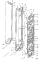
- Fig. 1 the inventive kit 1 with a mounting module 2, a lamp module 5 and a cover 36 is shown as a further module.
- the housing module 10 see for example Fig. 2
- the bridging module 66 see for example Fig. 6
- the intermediate module 69 see for example Fig. 8 described.
- the mounting module 2 has a substantially rectangular base plate 12, on the lamp module 5 assigning the front side 15 projects a substantially peripheral sealing strip 21 upwards. This has at its upper end a receiving groove 23 for receiving a seal, not shown. In bordered by the sealing strip 21 inner region four locking hooks 28 are arranged as locking elements 26, which protrude upward from the front side 15 and are arranged in pairs opposite one another along longitudinal sides of the base plate 12.
- terminals 3 are further arranged, which are passed to the rear side 82 of the base plate 12 and connectable to electrical leads, not shown.
- the terminals are assigned first plug contacts 4 and electrically connected thereto.
- essentially cylindrical spacers 14 are arranged which extend parallel to the latching hooks 28.
- blind holes 17 are formed, which corresponding holes 40 in a holding plate 30 of the lamp module 5 can be assigned.
- Ausrichtab arrangements 19 are arranged, on which an edge flange 20 of the holding plate 30 are arranged for relative alignment of the lamp module 5 to the mounting module 2.
- the Ausrichtab arrangements 19 are substantially stepped.
- mounting holes 13 Adjacent to the spacers 14 12 mounting holes 13 are arranged in the base plate. These are used to attach the mounting module 2 by means of, for example, screws on a wall or on a ceiling.
- the lamp module 5 has on a rear side 16, see Fig. 4 , the holding plate 30 and the lamp module 5 a protruding in the direction of the mounting module 2 sealing wall 24 which extends corresponding to the sealing strip 21 and from above on this and optionally arranged in the receiving groove 23 seal can be placed.
- a number of latching openings 41 are arranged in the latching elements 42, see FIGS. 5 and 6 a housing module 10 can be inserted and latched.
- a fluorescent tube On a front side 32 of the holding plate 30 are spaced apart sockets 6 and 7 for mounting and electrical supply of a fluorescent tube as a lamp. 8 arranged. Furthermore, 27 latching openings 29 are formed for latching with the latching hooks 28 of the mounting module 2 in the holding plate 30 as a counter-locking elements 27.
- a peripheral edge 31 surrounding the retaining plate 30 also has, in addition to the downwardly extending mounting flange 2 in the direction of mounting module 2, an outwardly projecting peripheral edge 77 which, in the manner of a tongue and groove connection in a corresponding insertion groove 76, see Fig. 10 , an intermediate module 69 can be inserted.
- a circumferential sealing projection 35 is arranged, which may be formed analogously to the sealing strip 21 of the mounting module 2 at its free end with a receiving groove for inserting a seal.
- this sealing projection 35 is a hood edge 37 of a patch on the lamp module 5 cover 36 as a further module sealing placed.
- the cover 36 has at its corners from the hood edge 37 outwardly projecting mounting bracket 38 with hole 39, which can be placed on the front side 32 of the support plate 30 in the bore 40.
- the bores 39 and 40 are cover and lamp module with each other and via the blind holes 17 with the mounting module 2 detachably connectable.
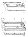
- Fig. 2 is a perspective top view of releasably connected assembly and lamp modules 2, 5 shown. These are by means of the holes 40 and the blind holes 17, see Fig. 1 , in the spacers 14 connected to each other. Furthermore, the latching hooks 28 with the corresponding latching openings 29 in latching engagement.
- the housing module 10 can be placed from above. This has on its the modules 2, 5 assigning back on a bridging module 66 with approximately semicircular in cross-section ends 65.
- the bridging module 66 covers the modules 2, 5 when the housing module 10 is attached and lies with its free ends 67, see Fig. 6 , on a wall or ceiling. Bridging module 66 and housing module 10 may also be formed optionally in one piece.
- a disc 11 made of clear plastic and / or opal translucent with a pictogram shown on the disc is arranged in the housing module 10.
- Fig. 3 is the bridging module 66 as compared to the embodiment of FIG Fig. 2 away.
- the housing module 10 has in lower sides 63 of its side walls 55, see FIGS. 5 and 6 , a downwardly open, circular segment-shaped recess 64 into which the bridging module 66, see Fig. 2 , is usable.
- Fig. 4 shows a bottom view of the lamp module 5.
- On the visible back 16 of the holding plate 30 are a number of supply lines 33 for the electrical supply of both the sockets 6, 7, see Fig. 1 , as well as further on the back of 16 arrangeable electronic components, such as an electronic ballast 34, respectively.
- Fig. 5 is a perspective top view of the housing module 10 after Fig. 2 without disc 11 shown.
- the housing module 10 has a disk opening 43, which is surrounded by an edge 48.
- a disc groove 47 for receiving a disc edge 49, see Fig. 3 be trained.
- the edge 48 is formed by extending between the side walls 55, 56 longitudinal edges 50, the longitudinal walls 52, see Fig. 6 are connected to corresponding longitudinal edges 51 of a module opening 45 in the housing module 10.
- the module opening 45 is in a rear side 46 of the housing module, see Fig. 6 , and the disc opening 43 in the front side 44, see Fig. 5 arranged.
- the longitudinal walls 52 extend obliquely from outside to inside to connect the corresponding longitudinal edges 50, 51.
- the front side 44 is convexly curved outward, see also the corresponding upper ends of the side walls 55, 56.
- the locking elements 42 are arranged by paired locking hooks 58 with mutually continuing latching lugs 59, see Fig. 6 , educated.
- Fig. 6 is a bottom perspective view of the housing module 10 with inserted therein or integrally formed therewith bridging module 66, see also Fig. 5 ,
- the bridging module 66 has the semi-circular ends 65 projecting outwardly beyond the side walls 55 of the housing module 10.
- the ends 65 are connected to one another via longitudinal walls 67.
- the longitudinal walls 67 extend in a curved manner away from the edge 22 of the module opening 45 in the direction of the lamp or mounting module 5, 2.
- the latching hooks 58 protrude within the longitudinal walls 67.
- the longitudinal walls 52 of the housing module 10 extend in the direction of the longitudinal edge 50 of the disc opening 43. Adjacent to the longitudinal edges 50 of the disc opening 43 52 ventilation slots 57 are formed in the longitudinal walls.
- Fig. 7 is a view analogous to Fig. 6 represented, wherein in the module opening 45, the lamp module 5 is inserted and the rear side 16, see also Fig. 4 , is visible.
- Fig. 8 is a perspective side view of a double-sided, constructed by the kit according to the invention light shown.
- the luminaire comprises two housing modules 10 and an intermediate module 69 arranged between them as a further module or as part of the housing module.
- the housing modules 10 are constructed according to the housing modules described above.
- corresponding slices 11 can be arranged on both front sides of the housing modules 10 .
- the housing modules are aligned with their backs to each other, wherein the module openings 45, see for example Fig. 5 , assign each other.
- mounting module 2 and lamp module 5 are not arranged in the module opening 45 of a housing module 10, but are in a corresponding insertion opening 70, see Fig. 10 , the intermediate module arranged.
- the lamp 8 extends between the longitudinal walls 52, see Fig. 6 , the two adjacently arranged housing modules 10, which is bounded by these longitudinal walls 52 in an approximately wedge-shaped space.
- the built-up of two sub-modules 71, 72 intermediate module 69 is used.
- Each sub-module 71, 72 is constructed the same and both sub-modules are arranged in mirror image to each other.
- Each sub-module 71, 72 has wedge surfaces 74 that can be assigned to the side surfaces 55, 56 of the housing module and a circular end plate 73 on one side. This is in the two mutually facing recesses 64, see Fig. 3 , the two adjacent housing modules 10 used.
- a sub-module 71 is alone with a housing module 10 in the FIGS. 9 and 10 and will be described below.
- each sub-module is connected to each other via a rail 75 which extends along the longitudinal wall 52 in the region of the ventilation slots 57, see Fig. 6 ,
- the rail 75 has on its side facing the other sub-module an insertion groove 76 into which the peripheral edge 77, see Fig. 1 , the lamp module 5, is pluggable.
- the Einstecknut 76 continues along the wedge walls 74 and forms together with the other sub-module 72, not shown, a closed border for the peripheral edge 77, so that the two sub-modules 71, 72 in a corresponding manner to a mounted on a ceiling by means of a mounting module 2 lamp module 5 are plugged.
- peripheral edge 77 and insertion 76 corresponds to a known tongue and groove connection.
- each sub-module 71, 72 has screw-on flanges 79 which protrude inwards perpendicular to the wedge surfaces 74. These are used for screwing with the holes 40 of the lamp module. 5
- each sub-module 71, 72 has a web 80 which extends along an edge of the mutually assigning module openings 45 of the two housing modules 10, see Fig. 8 , extends.
- the web 80 is curved perpendicular to its longitudinal direction corresponding to the end plate 73. From the web 80 are inwardly in the direction of module opening 45 Verschra lugs 81 from. These serve to screw the two sub-modules 71, 72, see Fig. 8 , It should be noted again that this is not in Fig. 10 shown further sub-module 72 of the same structure as sub-module 71 and is to be arranged in mirror image to this.
- the corresponding end plate 73 of the sub-module 72 is disposed opposite to the end plate 73 of the sub-module 71 in the corresponding recess of the two housing modules 10.
- connection between housing modules 10, see Fig. 8 and the two sub-modules 71, 72 also takes place via the Verschra flaps 81 and the Anschraubwinkel 60, see Fig. 6 ,
Landscapes
- Engineering & Computer Science (AREA)
- General Engineering & Computer Science (AREA)
- Power Engineering (AREA)
- Arrangement Of Elements, Cooling, Sealing, Or The Like Of Lighting Devices (AREA)
- Fastening Of Light Sources Or Lamp Holders (AREA)
- Non-Portable Lighting Devices Or Systems Thereof (AREA)
Claims (44)
- Ensemble de construction (1) de lampes d'éclairage de sécurité et de signalisations de secours, composé d'au moins- un module de montage (2) permettant de fixer la lampe d'éclairage, comprenant des lignes d'alimentation électrique et des borniers de raccordement (3) à brancher, et des premiers contacts à fiches (4) associés à ceux-ci, et- un module de lampe (5) comprenant des supports (6, 7) destinés à assurer le maintien et l'alimentation électrique d'une lampe (8), et des seconds contacts à fiches (9),caractérisé en ce que
le module de lampe (5) et le module de montage (2) peuvent être assemblés de façon démontable l'un avec l'autre en réalisant en même temps la mise en contact électrique entre les premiers et seconds contacts à fiches (4, 9), l'ensemble de construction (1) comprenant plusieurs modules de boîtiers (10) qui sont respectivement caractéristiques de chaque lampe, et qui peuvent être reliés chacun de façon démontable au module de montage (2) et/ou au module de lampe (5), une vitre (11) pouvant être éclairée par la lampe (8) pouvant être installée de façon démontable dans ledit module de boîtier (10). - Ensemble de construction selon la revendication 1, caractérisé en ce que le module de montage (2) présente une plaque d'embase essentiellement rectangulaire (12), dans laquelle sont aménagés des trous de fixation (13) pour son montage sur un mur ou un plafond.
- Ensemble de construction selon la revendication 2, caractérisé en ce que des entretoises (14) font saillie depuis une face avant (15) de la plaque d'embase (12), tournée vers le module de lampe (5), pour venir en contact avec une face arrière (16) du module de lampe.
- Ensemble de construction selon la revendication 3, caractérisé en ce que les entretoises (14) sont essentiellement cylindriques et comportent des trous borgnes (17) s'ouvrant en direction du module de lampe (5).
- Ensemble de construction selon l'une des revendications 3 ou 4, caractérisé en ce que les entretoises (14) comportent, à leurs extrémités libres (18), des talons d'alignement (19) qui peuvent être amenés en contact avec un rebord marginal (20) saillant depuis la face arrière (16) du module de lampe (5).
- Ensemble de construction selon l'une des revendications précédentes, caractérisé en ce qu'une barrette d'étanchéité périphérique (21) est formée sur la face avant (15) de la plaque d'embase (12), pour venir se plaquer de façon étanche sur le module de lampe (5) lorsque celui-ci est fixé sur le module de montage (2).
- Ensemble de construction selon la revendication 6, caractérisé en ce que la barrette d'étanchéité (21) comporte une rainure réceptrice (23) ouverte vers le haut, destinée à recevoir un joint d'étanchéité.
- Ensemble de construction selon l'une des revendications 6 ou 7, caractérisé en ce qu'une paroi d'étanchéité (24) s'étendant de façon analogue à la barrette d'étanchéité (21) fait saillie depuis la face arrière (6) du module de lampe (5).
- Ensemble de construction selon l'une des revendications précédentes, caractérisé en ce que des éléments d'enclenchement et des éléments d'enclenchement conjugués (26, 27) sont formés sur les modules de montage et de lampe (2, 5), qui peuvent être amenés en engagement mutuel de manière à réaliser un assemblage démontable des modules (2, 5) l'un avec l'autre.
- Ensemble de construction selon la revendication 9, caractérisé en ce que les éléments d'enclenchement (26) du module de montage (2) sont réalisés sous forme de crochets d'enclenchement (28) pouvant être élastiquement déviés et saillant depuis la face avant (15) de la plaque d'embase (12).
- Ensemble de construction selon l'une des revendications 9 ou 10, caractérisé en ce que les éléments d'enclenchement conjugués (27) du module de lampe (5) sont réalisés sous forme d'ouvertures d'enclenchement (29).
- Ensemble de construction selon la revendication 11, caractérisé en ce que le module de lampe (5) présente une plaque de maintien (30) essentiellement rectangulaire, depuis la face arrière (16) de laquelle s'étend la paroi d'étanchéité (24), et dans laquelle sont aménagées les ouvertures d'enclenchement (29).
- Ensemble de construction selon la revendication 12, caractérisé en ce que le rebord marginal (20) est réalisé sous forme d'un bord (31) entourant essentiellement toute la périphérie de la plaque de maintien (30).
- Ensemble de construction selon l'une des revendications 12 ou 13, caractérisé en ce que les supports (6, 7) notamment pour un tube fluorescent (8) sont disposés sur une face avant (32) de la plaque de maintien (30).
- Ensemble de construction selon l'une des revendications précédentes 12 à 14, caractérisé en ce que les seconds contacts à fiches (9) ainsi qu'au moins des lignes d'alimentation électrique (33) rejoignant les supports (6, 7) et un appareil électronique de ballast (34) pouvant être fixé de façon démontable à la face arrière, sont disposés à la face arrière (16) de la plaque de maintien (30).
- Ensemble de construction selon la revendication 14 ou 15, caractérisé en ce qu'une saillie d'étanchéité (35) essentiellement périphérique se projette depuis la face avant (32) de la plaque de maintien (30).
- Ensemble de construction selon l'une des revendications précédentes, caractérisé en ce qu'un module supplémentaire de l'ensemble de construction (1) est fixé de façon démontable sur le module de lampe (5), sous forme d'un capot de couverture (36).
- Ensemble de construction selon la revendication 17, caractérisé en ce que le capot (36) comporte un rebord de capot (37) périphérique correspondant à la saillie d'étanchéité (35) à la face avant (32) du module de lampe (5), rebord qui, lorsque le capot (36) est fixé sur le module de lampe (5), est en contact étanche avec la saillie d'étanchéité (35).
- Ensemble de construction selon la revendication 18, caractérisé en ce qu'un joint d'étanchéité peut être disposé entre la saillie d'étanchéité (35) et le bord du capot (37).
- Ensemble de construction selon la revendication 18 ou 19, caractérisé en ce que des équerres de fixation (38) font saillie vers l'extérieur depuis le bord du capot (37), des perçages (39) étant formés dans celles-ci pour permettre une fixation par vis dans les trous borgnes (17) ménagés dans les entretoises (14) ou les perçages correspondants (40) de la plaque de maintien (30).
- Ensemble de construction selon l'une des revendications précédentes, caractérisé en ce que le module de lampe (5) et/ou le module de montage (2) présentent des ouvertures d'enclenchement (41) permettant l'enclenchement des éléments d'enclenchement (42) saillant depuis le module de boîtier (10).
- Ensemble de construction selon la revendication 21, caractérisé en ce que les ouvertures d'enclenchement (41) sont disposées à l'extérieur, au bord (31) de la plaque de maintien et/ou à l'extérieur de la paroi d'étanchéité (24).
- Ensemble de construction selon l'une des revendications précédentes, caractérisé en ce que le module de boîtier (10) comporte une ouverture à vitre (43) ménagée dans sa face avant (44) destinée à recevoir la vitre (11), et une ouverture porte-module (45) ménagée dans sa face arrière (46), destinée à recevoir le module de montage et/ou de lampe (2, 5).
- Ensemble de construction selon la revendication 23, caractérisé en ce que la face avant (44) du module de boîtier (10) est incurvée de façon convexe vers l'extérieur.
- Ensemble de construction selon la revendication 23 ou 24, caractérisé en ce qu'une rainure (47) réceptrice de la vitre, au moins partiellement périphérique, est formée dans le bord (48) de l'ouverture à vitre (43) en vue de recevoir un bord de vitre (49) de la vitre (11), en particulier par enclenchement.
- Ensemble de construction selon l'une des revendications précédentes 23 à 25, caractérisé en ce que l'ouverture à vitre (43) est au moins plus large que l'ouverture porte-module (45), et que des parois longitudinales (52) du module de boîtier (10) s'étendent entre les bords longitudinaux (50, 51) de ces ouvertures (43, 45), des parois latérales (55, 56) étant disposées aux extrémités (53, 54) de ces parois longitudinales.
- Ensemble de construction selon la revendication 26, caractérisé en ce que les parois longitudinales (52) présentent des fentes de ventilation (57).
- Ensemble de construction selon l'une des revendications 23 à 27, caractérisé en ce que les éléments d'enclenchement (42) du module de boîtier (10) sont réalisés sous forme de crochets d'enclenchement (58) saillant depuis le bord (22) de l'ouverture porte-module (45) en direction du module de lampe (5).
- Ensemble de construction selon la revendication 28, caractérisé en ce que les crochets d'enclenchement (58) sont disposés par paires, avec des ergots d'enclenchement (59) dirigés dans des directions opposées.
- Ensemble de construction selon l'une des revendications précédentes 23 à 29, caractérisé en ce que des équerres de fixation par vis (60) sont disposées dans les coins (61) de l'ouverture porte-module (45), comportant des trous (62) permettant la fixation par vis dans les trous borgnes (17) des entretoises (14).
- Ensemble de construction selon l'une des revendications précédentes 26 à 30, caractérisé en ce que les parois latérales (55, 56) comportent, au niveau de leurs faces inférieures (63) dirigées vers le module de lampe (5), un évidement (64) en forme de segment de cercle, dans lequel peuvent être emboîtées les extrémités sensiblement semi-circulaires (65) d'un module de pontage (66), le module de pontage comprenant des parois longitudinales (67) s'étendant le long de l'ouverture porte-module (45), reliant ses extrémités (65) entre elles.
- Ensemble de construction selon la revendication 31, caractérisé en ce que le module de boîtier (10) et le module de pontage (66) sont réalisés d'un seul tenant.
- Ensemble de construction selon la revendication 31 ou 32, caractérisé en ce que les extrémités libres (68) des parois longitudinales (67) sont en contact avec une paroi ou un plafond lorsque le module de lampe (5) et/ou le module de montage (2) est fixé conjointement avec le module de boîtier (10).
- Ensemble de construction selon l'une des revendications précédentes 26 à 33, caractérisé en ce que, pour réaliser une lampe d'éclairage double face, deux modules de boîtiers (10) peuvent être assemblés en juxtaposant leurs ouvertures porte-modules (45), les modules de lampe et/ou de montage (5, 2) étant fixés de façon démontable essentiellement entre les parois longitudinales (52) des deux modules de boîtiers (10).
- Ensemble de construction selon l'une des revendications précédentes 26 à 34, caractérisé en ce qu'au moins un module intermédiaire (69) est disposé entre les parois longitudinales (52) des modules de boîtiers (10), module sur lequel les modules de boîtiers (10) peuvent être fixés de façon démontable, et qui comporte une ouverture d'insertion (70) s'étendant entre les parois longitudinales (52), dans laquelle peuvent être insérés les modules de montage ou de lampe (2, 5).
- Ensemble de construction selon la revendication 35, caractérisé en ce que le module de boîtier (10) et le module intermédiaire (69) sont formés d'un seul tenant.
- Ensemble de construction selon la revendication 35 ou 36, caractérisé en ce que le module intermédiaire (69) peut être assemblé à partir de deux sous-modules (71, 72) identiques, disposés de façon symétrique en miroir.
- Ensemble de construction selon la revendication 37, caractérisé en ce que chaque sous-module (71, 72) comporte une plaque terminale essentiellement circulaire (73) destinée à être insérée dans l'évidement (64) des parois latérales (55, 56) des deux modules de boîtiers (10), et des parois (74) en forme de coin pouvant être associées au moins aux deux parois latérales (55, 56), qui sont reliées les unes aux autres par l'intermédiaire d'un rail (75) s'étendant le long d'une paroi longitudinale (52) d'un module de boîtier (10).
- Ensemble de construction selon la revendication 38, caractérisé en ce que le rail (75) comprend une rainure d'emboîtement (76) permettant l'emboîtement d'un bord marginal périphérique (77) entourant la plaque de maintien (30).
- Ensemble de construction selon la revendication 39, caractérisé en ce que la rainure d'emboîtement (76) se prolonge le long des parois (74) en forme de coin.
- Ensemble de construction selon l'une des revendications précédentes 38 à 40, caractérisé en ce que des pattes de fixation par vis (79) permettant l'assemblage par vis avec les modules de lampe et/ou de montage (5, 2) se projettent essentiellement perpendiculairement depuis des extrémités supérieures (78) des parois en coin (74).
- Ensemble de construction selon l'une des revendications précédentes 37 à 41, caractérisé en ce que le sous-module (71, 72) comporte une nervure (80) placée en vis-à-vis du rail (75), pouvant être associée à un bord (22) des ouvertures porte-modules (45), d'où s'étendent des pattes de fixation par vis (81) en direction de l'ouverture porte-module (45), pattes qui peuvent être disposées en recouvrement avec des pattes de fixation par vis analogues (81) de l'autre sous-module (72, 71) et/ou avec les équerres de fixation par vis (60) du module de boîtier (10).
- Ensemble de construction selon l'une des revendications précédentes, caractérisé en ce que le module de montage (2) et/ou le module de lampe (5) et/ou le capot de couverture (36) sont réalisés en une matière plastique résistant à la chaleur.
- Ensemble de construction selon l'une des revendications précédentes, caractérisé en ce qu'au moins le module de montage (2) peut être relié, par sa face arrière (82), à un capot en vue de son montage pendulaire sur un plafond.
Applications Claiming Priority (2)
| Application Number | Priority Date | Filing Date | Title |
|---|---|---|---|
| DE29815480U DE29815480U1 (de) | 1998-08-28 | 1998-08-28 | Bausatz für Leuchten |
| DE29815480U | 1998-08-28 |
Publications (3)
| Publication Number | Publication Date |
|---|---|
| EP0982536A2 EP0982536A2 (fr) | 2000-03-01 |
| EP0982536A3 EP0982536A3 (fr) | 2002-04-03 |
| EP0982536B1 true EP0982536B1 (fr) | 2008-04-09 |
Family
ID=8061921
Family Applications (1)
| Application Number | Title | Priority Date | Filing Date |
|---|---|---|---|
| EP99115681A Expired - Lifetime EP0982536B1 (fr) | 1998-08-28 | 1999-08-09 | Ensemble d'éléments pour la formation de lampes |
Country Status (3)
| Country | Link |
|---|---|
| EP (1) | EP0982536B1 (fr) |
| AT (1) | ATE391886T1 (fr) |
| DE (2) | DE29815480U1 (fr) |
Families Citing this family (3)
| Publication number | Priority date | Publication date | Assignee | Title |
|---|---|---|---|---|
| GB0511331D0 (en) * | 2005-06-03 | 2005-07-13 | Ardent Products Ltd | Lighting system |
| TW201024607A (en) * | 2008-12-19 | 2010-07-01 | Crownmate Technology Co Ltd | Thin LED lamp structure |
| DE202012008802U1 (de) * | 2012-09-13 | 2014-01-09 | Ceag Notlichtsysteme Gmbh | Leuchte |
Family Cites Families (13)
| Publication number | Priority date | Publication date | Assignee | Title |
|---|---|---|---|---|
| US2617919A (en) * | 1947-09-17 | 1952-11-11 | Revere Copper & Brass Inc | Laterally expansible lighting fixture and part therefor |
| GB648426A (en) * | 1948-05-07 | 1951-01-03 | Wembley Electrical Appliances | Improvements in or relating to fluorescent and like lamp fittings |
| US2740885A (en) * | 1951-06-25 | 1956-04-03 | A L Smith Iron Company | Adjustable fluorescent light fixture |
| US3514590A (en) * | 1968-04-16 | 1970-05-26 | Calculations Inc | Fluorescent luminaire |
| DE7636602U1 (de) * | 1976-11-20 | 1977-05-18 | Hamacher, Martin, 4352 Herten | Leuchte |
| DE3442527A1 (de) * | 1983-11-23 | 1985-05-30 | Bösha GmbH & Co KG, 4780 Lippstadt | Langfeldleuchte fuer den einsatz in schlagwetter- und explosionsgeschuetzten bereichen |
| US5440470A (en) * | 1992-06-25 | 1995-08-08 | Peerless Lighting Corporation | Floating reflector assembly for a lighting fixture |
| IT1268521B1 (it) * | 1993-04-28 | 1997-03-04 | Marco Corazza | Plafoniera plurifunzionale di tipo protetto contro la penetrazione di spruzzi d'acqua, particolarmente applicabile a mensole di |
| US5379540A (en) * | 1993-11-17 | 1995-01-10 | The Howard Company | Modular sign system |
| DE4413316C2 (de) * | 1994-04-16 | 1998-07-16 | Reiss Int Gmbh | Leuchtenverschluß |
| DE4445164C2 (de) * | 1994-12-17 | 2002-03-07 | Ceag Sicherheitstechnik Gmbh | Sicherheits- und Rettungszeichenleuchte |
| IT241494Y1 (it) * | 1996-05-20 | 2001-05-09 | C F Srl | Struttura di astuccio modulare per assemblaggio di componentisticaelettrica, particolarmente per attrezzare mensole di mobili da bagno |
| DE29806792U1 (de) * | 1998-04-16 | 1998-06-25 | Norka Norddeutsche Kunststoff | Leuchte für langgestreckte Leuchtstofflampen, insbesondere in staub- und wasserdichter Ausführung |
-
1998
- 1998-08-28 DE DE29815480U patent/DE29815480U1/de not_active Expired - Lifetime
-
1999
- 1999-08-09 DE DE59914719T patent/DE59914719D1/de not_active Expired - Lifetime
- 1999-08-09 AT AT99115681T patent/ATE391886T1/de active
- 1999-08-09 EP EP99115681A patent/EP0982536B1/fr not_active Expired - Lifetime
Also Published As
| Publication number | Publication date |
|---|---|
| EP0982536A2 (fr) | 2000-03-01 |
| ATE391886T1 (de) | 2008-04-15 |
| DE59914719D1 (de) | 2008-05-21 |
| EP0982536A3 (fr) | 2002-04-03 |
| DE29815480U1 (de) | 2000-01-05 |
Similar Documents
| Publication | Publication Date | Title |
|---|---|---|
| EP1845396B1 (fr) | Eclairage doté d'au moins une couverture transparente | |
| DE19641835A1 (de) | Energiespar-Beleuchtungssystem | |
| DE2742334A1 (de) | Deckenanordnung sowie beleuchtungseinrichtungen fuer den einbau in derartige deckenanordnungen | |
| DE202016000122U1 (de) | Feuchtraumleuchte in Wannenbauform | |
| DE19953132A1 (de) | Fahrzeugleuchte | |
| DE8330300U1 (de) | Leuchte mit begleitender linearer lichtquelle | |
| EP1789724B1 (fr) | Lampe comportant des elements de fermeture destines a la fixation amovible d'un capot sur un boitier | |
| AT391616B (de) | Versorgungsbalken fuer die intensivpflege | |
| AT9599U1 (de) | Deckeneinbauleuchte | |
| EP0982536B1 (fr) | Ensemble d'éléments pour la formation de lampes | |
| DE102017203332B4 (de) | Leuchte | |
| DE102011083993A1 (de) | Lichtband | |
| WO2004020900A1 (fr) | Plafonnier comprenant un boitier allonge | |
| DE19721340A1 (de) | Leuchte | |
| EP0024580A1 (fr) | Lampe de signalisation ou feu de véhicule | |
| EP0616168A1 (fr) | Dispositif d'éclairage à cadre profilé | |
| DE3715559A1 (de) | Fluessigkristallanzeige | |
| EP1229288B1 (fr) | Lampe avec contrôle de l'alimentation de secours | |
| EP1337783A1 (fr) | Lampe dotee d'une plaque de recouvrement | |
| EP1132681B1 (fr) | Système de rails de support | |
| DE2757299A1 (de) | Anordnung zur befestigung von teilen in gehaeusen | |
| DE2330097A1 (de) | Anordnung von fassungen fuer leuchtstofflampen mit starter-fassungen | |
| DE2701620A1 (de) | Langfeldleuchte der schutzklasse ii | |
| DE2251972A1 (de) | Leistungsstrahler fuer halogenmetalldampf- oder dgl. lampen | |
| DE2619434A1 (de) | Innenleuchte fuer leuchtstofflampen |
Legal Events
| Date | Code | Title | Description |
|---|---|---|---|
| PUAI | Public reference made under article 153(3) epc to a published international application that has entered the european phase |
Free format text: ORIGINAL CODE: 0009012 |
|
| AK | Designated contracting states |
Kind code of ref document: A2 Designated state(s): AT BE CH CY DE DK ES FI FR GB GR IE IT LI LU MC NL PT SE Kind code of ref document: A2 Designated state(s): AT CH DE FR GB LI |
|
| AX | Request for extension of the european patent |
Free format text: AL;LT;LV;MK;RO;SI |
|
| PUAL | Search report despatched |
Free format text: ORIGINAL CODE: 0009013 |
|
| AK | Designated contracting states |
Kind code of ref document: A3 Designated state(s): AT BE CH CY DE DK ES FI FR GB GR IE IT LI LU MC NL PT SE |
|
| AX | Request for extension of the european patent |
Free format text: AL;LT;LV;MK;RO;SI |
|
| RIC1 | Information provided on ipc code assigned before grant |
Free format text: 7F 21V 15/00 A, 7G 09F 13/04 B |
|
| 17P | Request for examination filed |
Effective date: 20021002 |
|
| AKX | Designation fees paid |
Free format text: AT CH DE FR GB LI |
|
| RAP1 | Party data changed (applicant data changed or rights of an application transferred) |
Owner name: CEAG NOTLICHTSYSTEME GMBH |
|
| 17Q | First examination report despatched |
Effective date: 20050606 |
|
| 17Q | First examination report despatched |
Effective date: 20050606 |
|
| GRAP | Despatch of communication of intention to grant a patent |
Free format text: ORIGINAL CODE: EPIDOSNIGR1 |
|
| GRAS | Grant fee paid |
Free format text: ORIGINAL CODE: EPIDOSNIGR3 |
|
| GRAA | (expected) grant |
Free format text: ORIGINAL CODE: 0009210 |
|
| AK | Designated contracting states |
Kind code of ref document: B1 Designated state(s): AT CH DE FR GB LI |
|
| REG | Reference to a national code |
Ref country code: GB Ref legal event code: FG4D Free format text: NOT ENGLISH |
|
| REG | Reference to a national code |
Ref country code: CH Ref legal event code: NV Representative=s name: JACOBACCI & PARTNERS S.P.A. Ref country code: CH Ref legal event code: EP |
|
| REF | Corresponds to: |
Ref document number: 59914719 Country of ref document: DE Date of ref document: 20080521 Kind code of ref document: P |
|
| ET | Fr: translation filed | ||
| PLBE | No opposition filed within time limit |
Free format text: ORIGINAL CODE: 0009261 |
|
| STAA | Information on the status of an ep patent application or granted ep patent |
Free format text: STATUS: NO OPPOSITION FILED WITHIN TIME LIMIT |
|
| 26N | No opposition filed |
Effective date: 20090112 |
|
| REG | Reference to a national code |
Ref country code: CH Ref legal event code: PCAR Free format text: NEW ADDRESS: VIA LUGANETTO 3, 6962 LUGANO (CH) |
|
| REG | Reference to a national code |
Ref country code: FR Ref legal event code: PLFP Year of fee payment: 18 |
|
| REG | Reference to a national code |
Ref country code: FR Ref legal event code: PLFP Year of fee payment: 19 |
|
| REG | Reference to a national code |
Ref country code: FR Ref legal event code: PLFP Year of fee payment: 20 |
|
| PGFP | Annual fee paid to national office [announced via postgrant information from national office to epo] |
Ref country code: DE Payment date: 20180719 Year of fee payment: 20 Ref country code: FR Payment date: 20180720 Year of fee payment: 20 |
|
| PGFP | Annual fee paid to national office [announced via postgrant information from national office to epo] |
Ref country code: GB Payment date: 20180720 Year of fee payment: 20 Ref country code: AT Payment date: 20180723 Year of fee payment: 20 Ref country code: CH Payment date: 20180726 Year of fee payment: 20 |
|
| REG | Reference to a national code |
Ref country code: DE Ref legal event code: R071 Ref document number: 59914719 Country of ref document: DE |
|
| REG | Reference to a national code |
Ref country code: CH Ref legal event code: PL |
|
| REG | Reference to a national code |
Ref country code: GB Ref legal event code: PE20 Expiry date: 20190808 |
|
| REG | Reference to a national code |
Ref country code: AT Ref legal event code: MK07 Ref document number: 391886 Country of ref document: AT Kind code of ref document: T Effective date: 20190809 |
|
| PG25 | Lapsed in a contracting state [announced via postgrant information from national office to epo] |
Ref country code: GB Free format text: LAPSE BECAUSE OF EXPIRATION OF PROTECTION Effective date: 20190808 |