EP0982145B1 - Mécanisme support et dispositif de transport et appareil d'enregistrement - Google Patents
Mécanisme support et dispositif de transport et appareil d'enregistrement Download PDFInfo
- Publication number
- EP0982145B1 EP0982145B1 EP99116683A EP99116683A EP0982145B1 EP 0982145 B1 EP0982145 B1 EP 0982145B1 EP 99116683 A EP99116683 A EP 99116683A EP 99116683 A EP99116683 A EP 99116683A EP 0982145 B1 EP0982145 B1 EP 0982145B1
- Authority
- EP
- European Patent Office
- Prior art keywords
- sheet
- roller
- bearing
- pinching
- conveying
- Prior art date
- Legal status (The legal status is an assumption and is not a legal conclusion. Google has not performed a legal analysis and makes no representation as to the accuracy of the status listed.)
- Expired - Lifetime
Links
Images


Classifications
-
- B—PERFORMING OPERATIONS; TRANSPORTING
- B41—PRINTING; LINING MACHINES; TYPEWRITERS; STAMPS
- B41J—TYPEWRITERS; SELECTIVE PRINTING MECHANISMS, i.e. MECHANISMS PRINTING OTHERWISE THAN FROM A FORME; CORRECTION OF TYPOGRAPHICAL ERRORS
- B41J13/00—Devices or arrangements of selective printing mechanisms, e.g. ink-jet printers or thermal printers, specially adapted for supporting or handling copy material in short lengths, e.g. sheets
- B41J13/02—Rollers
- B41J13/076—Construction of rollers; Bearings therefor
Definitions
- the present invention relates to a roller supporting apparatus according to the first part of claim 1.
- Recording apparatuses having a function as a printer, a copying machine or a facsimile, or recording apparatuses used as output devices for composite electronic equipments including a computer or a word processor or as output devices for work stations are designed that an image is on a sheet to be recorded (recording medium) such as a paper sheet or a plastic thin sheet based on image information.
- Such recording apparatuses can be divided into an ink jet system, a wire dot system, a thermal system, a laser beam system and the like, in dependence upon a recording style.
- a serial type recording apparatus having a serial scanning system in which main scanning is effected along a direction transverse to a conveying direction (sub-scanning direction) of the sheet to be recorded, the entire image is recorded by recording means mounted on a carriage movable along the sheet to be recorded, by repeating one-line recording effected by the main scanning and a predetermined amount sheet feeding (pitch conveyance) alternately.
- the recording apparatus of ink jet type is designed to effecting the recording by discharging ink from recording means (a recording head) onto the sheet to be recorded.
- This recording apparatus has advantages that the recording means can easily be made compact, a fine image can be recorded at a high speed, the recording can be effected on a plain paper without special treatment, a running cost is inexpensive, noise can be suppressed due to non-impact recording and a color image can easily be recorded by using multi color inks.
- Fig. 13 is a front view of such a recording apparatus and Fig. 14 is a sectional view of the recording apparatus.
- a sheet feeding portion 503 is attached to a chassis 508 formed by bending a metal sheet.
- the sheet feeding portion 503 includes a conveying roller 536 for conveying a sheet P' and a PE sensor (sheet end detecting device) 532.
- the conveying roller 536 is constituted by wounding an elastic material such as rubber around a surface of a metal shaft and is attached to the chassis 508 by mounting both ends of the metal shaft within conductive bearings 538, 539.
- a conveying roller tension spring 681 is disposed between the bearing 538 and the conveying roller 536 to apply load to the conveying roller 536 on rotating thereby to provide stable conveyance. Namely, by biasing the conveying roller 536 through the spring 681, predetermined load is applied.
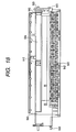
- the conveying roller 536 is attached as follows. First of all, one end of the metal shaft of the conveying roller 536 is inserted into the bearing 539 and then is attached to the chassis 508. Then, the other end of the metal shaft of the conveying roller 536 is passed through a cut out portion of the chassis 508. Then, the conveying roller tension spring 681 is attached and the bearing 538 is fitted into the chassis 508 while inserting the bearing 538 onto the shaft of the conveying roller 536 from outside. In this case, a pawl portion 686 of the bearing 538 enters into a groove portion 661 formed in the conveying roller 536, so that the conveying roller 536 is secured to the chassis 508. An assembled condition is shown in Fig. 15B.
- a plurality of driven pinch rollers 537 abut against the conveying roller 536.
- the pinch rollers 537 are held by a pinch roller guide 530 pivotally mounted on a shaft 530a and are biased by a pinch roller spring 531 to urge the pinch rollers 537 against the conveying roller 536, thereby providing a conveying force for the sheet P'.
- the pinch rollers 537 are arranged so that they do not cover the entire area of the sheet P' but divided to hold only predetermined ranges of the sheet.
- the rotation shaft 530a of the pinch roller guide 530 is attached to bearings of an upper guide 533 for rotation.
- an inlet of the sheet feeding portion 503 to which the sheet P' is conveyed is provided with the upper guide 533 and a platen 534 which guide the sheet P'.
- the upper guide 533 is provided with a PE sensor lever 535 for transmitting detection of leading and trailing ends of the sheet P' to the PE sensor 532.
- the platen 534 is positioned by a bearing portion 642 fitted and slidable on the conveying roller 536 to be attached to the chassis 508, and an attachment shaft 643 directly attached to the chassis 508. Further, a sheet holding-down portion 544 for conveying a side edge of the sheet P' is provided at a sheet reference side of the platen 534.
- the recording head 507 for forming an image based on image information is disposed at a downstream side of the conveying roller 536 in a conveying direction of the sheet P'.
- the sheet P' fed to the sheet feeding portion 503 is guided by the platen 534, pinch roller guide 530 and upper guide 533 to be sent to a pair of rollers (conveying roller 536 and pinch rollers 537).
- the PE sensor lever 535 detects the leading end of the sheet P' being conveyed, thereby determining a printing position of the sheet P'. Further, the sheet P' is conveyed on the platen 534 by rotating the pair of rollers 536, 537 by an LF motor (not shown).
- the recording head 507 is an easy exchangeable ink jet recording head integrally formed with an ink tank.
- heat can be applied to ink by a heater or the like.
- the ink is film-boiled by the heat to cause growth and contraction of a bubble to generate a change in pressure by which the ink is discharged from a nozzle 570 of the recording head 507, thereby forming the image on the sheet P'.
- a transmitting roller 540 abuts against the conveying roller 536 and further abuts against a sheet discharging roller 541. Accordingly, a driving force of the conveying roller 536 is transmitted to the sheet discharging roller 541 through the transmitting roller 540. Further, a spur roller 542 abuts against the sheet discharging roller 541 to be driven by rotation of the sheet discharging roller 541.
- the spur roller 542 is attached to a spur stay 641 of integral type provided on the platen 534.
- the spur stay 641 has a partially cut-away portion 641a.
- the carriage 550 is moved up to the cut-away portion 641a to create a space through which a hook lever 553 for mounting and dismounting the head 507 can be manipulated.
- the sheet P' on which the image was formed in a carriage portion 505 is pinched by a nip between the sheet discharging roller 541 and the spur roller 542 to be conveyed and discharged onto a sheet discharging tray (not shown).
- the groove portion 661 In the attachment of the conveying roller 536 to the chassis 508, as shown in Figs. 5A and 15B, the groove portion 661 must be formed in the metal shaft of the conveying roller 536 and the pawl portion 686 must be provided on the bearing 538 corresponding to the groove 661 (Fig. 15A). Thus, the number of manufacturing steps is increased, thereby making the manufacturing cost more expensive. In addition, when the pawl 686 is disengaged, the pawl may be damaged, thereby causing a problem regarding operability.
- the pinch rollers 537 do not hold down the entire area of the sheet P', as shown in Fig. 16, if the side edge of the sheet P' is warped, the sheet cannot enter below the sheet holding-down portion 644 but rides over the sheet holding-down portion 644, with the result that the side edge of the sheet P' may interfere with the carriage 550 or the recording head 507.
- a trailing end of the sheet P' may be floating after it was discharged.
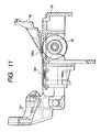
- the trailing end of the sheet P' is pinched between the spur roller 542 and a spur roller cleaner 543 or a spur roller attaching portion 641 of the platen 534, poor sheet discharging will occur or the sheet P' will be damaged by the spur roller 542 (Fig. 17).
- a roller supporting apparatus according to the first part of claim 1 is known from the document DE 38 34 564 A1. Means for a stabelized support of the roller shaft without play are not mentioned.
- the present invention aims to eliminate the above-mentioned conventional drawbacks, and an object of the present invention is to provide a roller supporting apparatus with a bearing mechanism in which a groove portion in a shaft and a pawl portion on a bearing corresponding to the groove portion are not required and which can improve production efficiency and operability, and a conveying apparatus which has such a bearing mechanism and an image forming apparatus having such a conveying apparatus.
- the present invention provides a roller supporting apparatus as defined in claim 1.
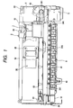
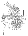
- a recording apparatus 1 having an auto sheet feeder comprises a sheet supplying portion 2, a sheet feeding portion 3, a sheet discharging portion 4, a carriage portion 5 and a cleaning portion 6. Now, these portions will be briefly described in order.
- Fig. 1 is a front view of the recording apparatus 1
- Fig. 2 is a sectional view of the recording apparatus 1.
- the sheet supplying portion 2 includes a base 20 to which a pressure plate 21 for stacking sheets P and a supply rotary member 22 for supplying the sheet P are attached.
- a movable side guide 23 is movably mounted on the pressure plate 21 to regulate a stacking position for the sheet P.
- the pressure plate 21 can be rotated around a rotary shaft connected to the base 20 and is biased toward the supply rotary member 22 by a pressure plate spring 24.
- a separating pad 25 formed from material having great coefficient of friction such as synthetic leather for preventing double-feed of the sheets P is provided on a portion of the pressure plate 21 opposed to the supply rotary member 22.
- the base 20 is provided with a separation pawl 26 for covering one corner of the sheet stack and for separating the sheets P one by one, a bank portion 27 integrally formed with the base 20 to separate sheets (which cannot be separated by the separation pawl 26) such as thick sheets, and a release cam 29 for releasing abutment between the pressure plate 21 and the supply rotary member 22.
- the separation pawl 26 is fixed while serving to separate the sheets one by one.
- the sheets are separated one by one while moving the separation pawl 26.
- the supply rotary member 22 and the release cam 29 are rotated until the sheet P is fed into the sheet feeding portion 3. Thereafter, the waiting condition in which the abutment between the sheet P and the supply rotary member 22 is released is established again, and the driving force from the conveying roller 36 is not transmitted.
- the sheet feeding portion 3 is attached to a chassis 8 formed by bending a metal sheet.
- the sheet feeding portion 3 includes the conveying roller 36 for conveying the sheet P and a PE sensor 32.
- the conveying roller 36 is constituted by wounding an elastic material such as rubber around a surface of a metal shaft and is attached to the chassis 8 by mounting both ends of the metal shaft within conductive bearings 38, 39.
- a conveying roller tension spring (elastic member) 381 is disposed between the bearing 38 and the conveying roller 36 to apply load to the conveying roller 36 on rotating thereby to provide stable conveyance. Namely, by biasing the conveying roller 36 by the spring 38, predetermined load is applied.
- a plurality of driven pinch rollers 37 abut against the conveying roller 36.
- the pinch rollers 37 are held by a pinch roller guide 30 and are biased by a pinch roller spring 31 to urge the pinch rollers 37 against the conveying roller 36, thereby providing a conveying force for the sheet P.
- the pinch rollers 37 are arranged so that they do not cover the entire area of the sheet P but cover only predetermined divided ranges of the sheet.
- a rotation shaft 30a of the pinch roller guide 30 is attached to bearings of an upper guide 33 for rotation.
- an inlet of the sheet feeding portion 3 to which the sheet P is conveyed is provided with the upper guide 33 and a platen 34 which guide the sheet P.
- the upper guide 33 is provided with a PE sensor lever 35 for transmitting detection of leading and trailing ends of the sheet P to the PE sensor 32.
- the platen 34 is positioned by bearing portions 342 fitted and slidable on the conveying roller 36 to be attached to the chassis 8, and an attachment shaft 343 directly attached to the chassis 8.
- a sheet holding-down portion 344 for covering a side edge of the sheet P is provided at a sheet reference side of the platen 34.
- the sheet P fed to the sheet feeding portion 3 is guided by the platen 34, pinch roller guide 30 and upper guide 33 to be sent to a pair of rollers (conveying roller 36 and pinch rollers 37).
- the PE sensor lever 35 detects the leading end of the sheet P being conveyed, thereby determining a printing position of the sheet P.
- the sheet P is conveyed on the platen 34 by rotating the pair of rollers 36, 37 by an LF motor (driving means) LFM.
- the recording head 7 is an easy exchangeable ink jet recording head integrally formed with an ink tank.
- heat can be applied to ink by a heater or the like.
- the ink is film-boiled by the heat to cause growth and contraction of a bubble to generate a change in pressure by which the ink is discharged from a nozzle 70 of the recording head 7, thereby forming the image on the sheet P.
- the carriage portion 5 includes the carriage 50 on which the recording head 7 is mounted.
- the carriage 50 is supported by a guide shaft 81 for causing reciprocal scanning of the carriage along a direction perpendicular to the conveying direction of the sheet P, and a guide rail 82 for holding a rear end of the carriage 50 to maintain a gap between the recording head 7 and the sheet P.
- the guide shaft 81 is attached to the chassis 8.
- the guide rail 82 is integrally formed with the chassis 8.
- chassis 8 since rigidity of the chassis 8 is increased by the bending of the guide rail 82, reliability regarding strength is enhanced. Incidentally, if the conventional strength is adequate, since a thickness of the metal sheet forming the chassis 8 can be reduced, the cost of the apparatus can be further reduced.
- the carriage 50 is driven by a carriage motor 80 attached to the chassis 8, via a timing belt 83.
- the timing belt 83 is supported by an idle pulley 84, and tension is maintained in the timing belt by this idle pulley.
- the carriage 50 is provided with a flexible substrate 56 for transmitting a head signal from an electric substrate 9 to the recording head 7.
- the sheet P when the image is formed on the sheet P, the sheet P is conveyed to an image forming row position (position in the conveying direction of the sheet P) by the pair of rollers 36, 37 and the carriage 50 is shifted to an image forming column position (position in the direction perpendicular to the conveying direction of the sheet P) by the carriage motor 80, so that the recording head 7 is opposed to an image forming position. Thereafter, based on the signal from the electric substrate 9, the recording head 7 discharges the ink toward the sheet P, thereby forming the image.
- a transmitting roller 40 abuts against the conveying roller 36 and further abuts against a sheet discharging roller 41. Accordingly, a driving force of the conveying roller 36 is transmitted to the sheet discharging roller 41 through the transmitting roller 40. Further, spurs 42 abut against the sheet discharging roller 41 to be driven by rotation of the sheet discharging roller.
- the spurs 42 are attached to a spur stay 341 of integral type provided on the platen 34.
- a spur stay 341 integral with the platen 34 in this way, since dimensions of the spurs 42 and the sheet discharging roller 41 can be controlled within the same part, a dimensional relationship can be kept stably.
- the spur stay 341 has a partially cut-away portion 346.
- the carriage 50 is moved up to the cut-away portion to create a space through which a hook lever 53 for mounting and dismounting the head 7 can be manipulated.
- the sheet P on which the image was formed in a carriage portion 5 is pinched by a nip between the sheet discharging roller 41 and the spurs 42 to be conveyed and discharged onto a sheet discharging tray (not shown).
- the cleaning portion 6 includes a pump for cleaning the recording head 7, a cap for avoiding a dry of the recording head 7, and a drive switching arm for switching the driving force from the conveying roller 36 between the sheet supplying portion 2 and the pump.
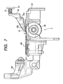
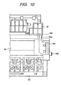
- Figs. 3A to 3C and Figs. 4A and 4B show a method for attaching the conveying roller 36 using the bearing mechanism according to the present invention.
- Fig. 3A is a left side view of the bearing
- Fig. 3B is a front view of the bearing
- Fig. 3C is a right side view of the bearing
- Fig. 4A is a view showing a condition that the bearing is fitted in a supporting plate
- Fig. 4B is a view showing a condition that the bearing is rotated and fixed after the fitting.
- one end of the metal shaft of the conveying roller 36 is inserted into the bearing 39 and then is attached to the chassis (supporting plate) 8. Then, the other end of the metal shaft of the conveying roller 36 is passed through a cut out portion (8a) of the chassis 8.
- the conveying roller tension spring 381 is attached and a fitting portion 387 (hatched portion in Fig. 3B) of the bearing 38 is fitted into the chassis 8 while inserting the bearing 38 onto the shaft of the conveying roller 36 from outside (Fig. 4A).
- the pinching portion 382 for receiving the inner side of the chassis 8 passes through the cut out portion 8a of the chassis 8.
- the chassis 8 is pinched between the two pinching portions 382, 388 of the bearing 38 at a position where the inner side and the outer side of the chassis 8 are opposed, thereby preventing dislodgment in the axial direction. Further, the chassis receives the biasing force of the conveying roller tension spring 381.
- a regulating portion (detent) 384 as fixing means is provided on the bearing 38, and a corresponding regulating portion 89 is provided on the chassis 8.
- the regulating portion or protrusion (detent) 384 of the bearing 38 enters into the regulating portion or hole (detent) 89 of the chassis 8, thereby preventing the bearing 38 from removing from the chassis 8.
- the biasing force of the conveying roller tension spring 381 acts on a portion of the pinching portion 382 of the bearing 38 receiving the inner side of the chassis 8. Since the portion of the first pinching portion 382 of the bearing 38 receiving the inner side of the chassis 8 is offset, a force for inclining the bearing 38 around a point P1 acts along a direction shown by the arrow A. This force can be supported by a surface (abutting portion) 388a of the second pinching portion 388 of the bearing 38 receiving the outer side of the chassis 8 in a direction shown by the arrow B. In this way, the conveying roller 36 is positioned and stabilized.
- the pinch rollers 37 do not hold-down the entire conveying area of the sheet P but only hold down predetermined four widths on the sheet. By making the pinch rollers 37 smaller and shorter, the cost can be reduced.
- the pinch roller guide 30 for holding the pinch rollers 37 and for urging the pinch rollers against the conveying roller 36 is formed from one-piece member which has certain rigidity at areas where the pinch rollers 37 exist and substantially no rigidity at areas where the pinch rollers 37 do not exist.
- the force of the pinch roller spring 31 effectively acts on the pinch rollers 37. Further, at the areas where the pinch rollers 37 do not exist, there are provided guide ribs 302 for preventing the sheet P from floating.
- a guide portion 303 for directing the side edge of the sheet P under the sheet holding-down portion 344.
- the guide portion 303 has a section corresponding to a part of the configuration of the pinch roller 37.
- the guide portion has a smooth tapered surface extending from the outer periphery of the pinch roller 37 toward an upstream side of the sheet P conveying direction.
- ribs 345 as protection members for preventing the sheet P from being caught up provided on a spur roller attaching portion 341 of the spur stay of the platen 34 are arranged on both sides of all of the spurs 42.
- one of the pinching portions may have a hole configuration 385 greater than a configuration of the corresponding other pinching portion.
- any slide portion can be eliminated from a mold, so that parts can be molded with a simple construction, thereby stabilizing performance and reducing cost.
- the guide portion 303 may be provided on the sheet holding-down portion 344 itself.
- the sheet holding-down portion 344 has an extension 344a extending up to the upstream of the pinch rollers 37 in the conveying direction of the sheet P so that the extension 344a is overlapped with the pinch roller guide 30.
- the sheet P is directed under the sheet holding-down portion 344 more positively.
- the ribs provided on the spur attaching portion 341 of the spur stay of the platen 34 are arranged on both sides of all of the spurs 42 was explained, such ribs may be arranged only outside of outermost spurs 42.
- the ribs (protection members) 345 are provided only outside of the outermost spurs 42. Also in this case, since both side edges of the trailing end of the sheet P can be received, sheet catching preventing effect can be achieved.
- the present invention has the above-mentioned construction and function, it is not required that any groove portion be formed in the shaft portion and any pawl be formed on the bearing, with the result that the number of manufacturing steps is reduced, production efficiency can be improved and the cost can be reduced. Further, since there is no damage of the pawl on the bearing, operability is also improved.
Landscapes
- Delivering By Means Of Belts And Rollers (AREA)
- Ink Jet (AREA)
Claims (7)
- Dispositif de support de rouleau comprenant :un rouleau (36) comportant un arbre ;des paliers (38) destinés à supporter avec possibilité de rotation ledit arbre aux deux extrémités dudit rouleau (36),une plaque de support (8) comportant une partie d'ouverture (8a) destinée à maintenir l'un desdits paliers (38) ; oùledit un desdits paliers (38) comporte une paire de parties de pincement (382, 388) destinées à pincer ladite plaque de support (8) des deux côtés pour maintenir ledit palier (38) sur ladite plaque de support (8),caractérisé en ce que
la paire de parties de pincement (382, 388) s'étend dans une première direction radiale dudit arbre afin d'être supportées,
le dispositif de support de rouleau comprend en outre un élément élastique (381) disposé entre ledit au moins un desdits paliers (38) et ledit rouleau (36) en vue de solliciter ledit rouleau et ledit palier (38) pour qu'ils se séparent l'un de l'autre ; et
une seconde partie de pincement (388) desdites parties de pincement (382, 388), éloignée dudit rouleau (36) par rapport à ladite plaque de support (8), est dotée d'une partie de butée qui bute contre ladite plaque de support (8) de manière à régler l'inclinaison dudit palier (38) vis-à-vis d'un moment généré par une première partie de pincement (382) desdites parties de pincement à proximité dudit rouleau (38) par rapport à ladite plaque de support (8) et d'une force de sollicitation dudit élément élastique (381). - Dispositif de support de rouleau selon la revendication 1, dans lequel ladite seconde partie de pincement (388) est plus longue que ladite première partie de pincement (382).
- Dispositif de support de rouleau selon la revendication 1, dans lequel ladite seconde partie de pincement (388) est dotée d'une partie de réglage (384) destinée à régler la rotation dudit palier (38) autour dudit arbre.
- Dispositif de support de rouleau selon la revendication 1, comprenant en outre un moyen d'entraînement destiné à entraîner par rotation ledit rouleau.
- Dispositif de transport de feuille comprenant un dispositif de support de rouleau présentant les caractéristiques selon l'une quelconque des revendications précédentes, comprenant en outre :un rouleau de pincement (37) coopérant avec ledit rouleau (36) pour pincer et transporter une feuille (P).
- Dispositif de formation d'image comprenant un dispositif de transport de feuille présentant les caractéristiques de la revendication 5, comprenant en outre :un moyen de formation d'image destiné à former une image sur la feuille (P) transportée par ledit rouleau (36).
- Dispositif de formation d'image selon la revendication 6, dans lequel ledit moyen de formation d'image forme l'image en déchargeant une gouttelette d'encre sur une surface de la feuille (P).
Applications Claiming Priority (2)
| Application Number | Priority Date | Filing Date | Title |
|---|---|---|---|
| JP25756998 | 1998-08-27 | ||
| JP25756998 | 1998-08-27 |
Publications (3)
| Publication Number | Publication Date |
|---|---|
| EP0982145A2 EP0982145A2 (fr) | 2000-03-01 |
| EP0982145A3 EP0982145A3 (fr) | 2001-09-26 |
| EP0982145B1 true EP0982145B1 (fr) | 2006-12-13 |
Family
ID=17308102
Family Applications (1)
| Application Number | Title | Priority Date | Filing Date |
|---|---|---|---|
| EP99116683A Expired - Lifetime EP0982145B1 (fr) | 1998-08-27 | 1999-08-26 | Mécanisme support et dispositif de transport et appareil d'enregistrement |
Country Status (4)
| Country | Link |
|---|---|
| US (1) | US6382857B1 (fr) |
| EP (1) | EP0982145B1 (fr) |
| CN (1) | CN1177262C (fr) |
| DE (1) | DE69934367T2 (fr) |
Families Citing this family (10)
| Publication number | Priority date | Publication date | Assignee | Title |
|---|---|---|---|---|
| US6824132B2 (en) | 2001-05-10 | 2004-11-30 | Canon Kabushiki Kaisha | Sheet feeding apparatus and recording apparatus |
| US7040614B2 (en) * | 2002-02-18 | 2006-05-09 | Canon Kabushiki Kaisha | Sheet feeding device and recording apparatus |
| US7165765B2 (en) * | 2002-06-07 | 2007-01-23 | Canon Kabushiki Kaisha | Sheet feeding apparatus and recording apparatus |
| KR100485782B1 (ko) * | 2003-01-04 | 2005-04-28 | 삼성전자주식회사 | 화상형성장치의 용지배출장치 |
| US7401915B2 (en) * | 2004-07-28 | 2008-07-22 | Brother Kogyo Kabushiki Kaisha | Image-recording apparatus |
| JP4769438B2 (ja) * | 2004-08-12 | 2011-09-07 | キヤノン株式会社 | 記録装置、データ生成方法、プログラムおよび記録方法 |
| US7128317B2 (en) * | 2004-09-10 | 2006-10-31 | Lexmark International, Inc. | Moveable media dam |
| EP1820656B1 (fr) * | 2006-02-20 | 2010-04-28 | Canon Kabushiki Kaisha | Appareil d'enregistrement |
| US10647132B2 (en) | 2016-06-23 | 2020-05-12 | Hewlett-Packard Development Company, L. P. | Partially dried inkjet media output management |
| CN110159661B (zh) * | 2019-04-16 | 2021-11-30 | 深圳市速腾聚创科技有限公司 | 机械式激光雷达的轴承预紧结构 |
Family Cites Families (21)
| Publication number | Priority date | Publication date | Assignee | Title |
|---|---|---|---|---|
| DE2941172C2 (de) | 1979-10-11 | 1982-09-09 | Triumph-Adler Aktiengesellschaft für Büro- und Informationstechnik, 8500 Nürnberg | Lagerteil, z.B. für die Achse einer Schreibwalze in Büromaschinen |
| JPS618852A (ja) | 1984-06-22 | 1986-01-16 | Sanyo Electric Co Ltd | 非水電解液電池 |
| FR2566857B1 (fr) * | 1984-06-28 | 1986-12-26 | Sagem | Agencement de palier d'arbre monobloc a montage par encliquetage |
| DE3834564A1 (de) | 1988-10-11 | 1990-04-12 | Olympia Aeg | Lagerung fuer wellen und/oder achsen |
| US5648808A (en) | 1991-06-10 | 1997-07-15 | Canon Kabushiki Kaisha | Automatic sheet feeding apparatus |
| JP2925368B2 (ja) | 1991-07-25 | 1999-07-28 | キヤノン株式会社 | シート給送装置及び画像形成装置 |
| JP2872452B2 (ja) | 1991-07-30 | 1999-03-17 | キヤノン株式会社 | 自動給紙装置及び記録装置 |
| ATE208279T1 (de) | 1992-07-31 | 2001-11-15 | Canon Kk | Blattfördervorrichtung |
| JP3197960B2 (ja) | 1992-09-30 | 2001-08-13 | キヤノン株式会社 | 自動給送装置及び画像形成装置 |
| JP3098369B2 (ja) | 1993-12-15 | 2000-10-16 | キヤノン株式会社 | シート給送装置及び記録装置 |
| US5534902A (en) | 1994-04-01 | 1996-07-09 | Xerox Corporation | Holddown structures for recording medium having curl |
| JP3437319B2 (ja) | 1994-04-05 | 2003-08-18 | キヤノン株式会社 | インクジェット記録装置およびインクジェット画像形成方法 |
| DE69609217T2 (de) | 1995-02-28 | 2000-11-30 | Hewlett-Packard Co., Palo Alto | Medientransport bei einem Tintenstrahldrucker |
| US5527123A (en) * | 1995-02-28 | 1996-06-18 | Hewlett-Packard Company | Media handling in an ink-jet printer |
| US5918873A (en) | 1995-03-30 | 1999-07-06 | Canon Kabushiki Kaisha | Sheet supplying apparatus which regulates tip end of sheet by first and second abutment means |
| JP3584085B2 (ja) * | 1995-06-09 | 2004-11-04 | セイコーエプソン株式会社 | プリンタ |
| US5807003A (en) * | 1995-05-24 | 1998-09-15 | Seiko Epson Corporation | Sheet discharge section for a printer |
| JPH09142712A (ja) * | 1995-11-20 | 1997-06-03 | Brother Ind Ltd | プリンタ |
| KR100209519B1 (ko) * | 1996-08-30 | 1999-07-15 | 윤종용 | 잉크젯프린팅헤드를 이용한 기기에 있어서 용지급지장치 |
| JP3666139B2 (ja) * | 1996-09-26 | 2005-06-29 | ブラザー工業株式会社 | 印字装置 |
| JP3767061B2 (ja) * | 1997-02-05 | 2006-04-19 | ブラザー工業株式会社 | 印字装置 |
-
1999
- 1999-08-23 US US09/379,356 patent/US6382857B1/en not_active Expired - Fee Related
- 1999-08-26 DE DE69934367T patent/DE69934367T2/de not_active Expired - Lifetime
- 1999-08-26 EP EP99116683A patent/EP0982145B1/fr not_active Expired - Lifetime
- 1999-08-27 CN CNB991181603A patent/CN1177262C/zh not_active Expired - Fee Related
Also Published As
| Publication number | Publication date |
|---|---|
| US6382857B1 (en) | 2002-05-07 |
| DE69934367D1 (de) | 2007-01-25 |
| DE69934367T2 (de) | 2007-09-27 |
| EP0982145A2 (fr) | 2000-03-01 |
| EP0982145A3 (fr) | 2001-09-26 |
| CN1246661A (zh) | 2000-03-08 |
| CN1177262C (zh) | 2004-11-24 |
Similar Documents
| Publication | Publication Date | Title |
|---|---|---|
| EP0581276B1 (fr) | Dispositif pour le transport de feuilles | |
| US6659444B2 (en) | Sheet feed apparatus, and recording apparatus having sheet feed apparatus | |
| EP1731316B1 (fr) | Appareil thermique de formation d'image | |
| JP3372800B2 (ja) | 記録装置 | |
| EP0982145B1 (fr) | Mécanisme support et dispositif de transport et appareil d'enregistrement | |
| KR970004230B1 (ko) | 잉크제트프린터 | |
| JP4817878B2 (ja) | 記録装置 | |
| US6170817B1 (en) | Sheet feeding apparatus | |
| EP0927640B1 (fr) | Imprimante avec mécanisme amélioré pour la manipulation du support d'impression | |
| JP4174534B2 (ja) | 記録装置 | |
| JP2007160879A (ja) | 画像記録装置 | |
| JP3495932B2 (ja) | シート給送装置及び記録装置 | |
| JP3322052B2 (ja) | インクジェットプリンタ | |
| KR100919067B1 (ko) | 기록 장치 | |
| JPH1179470A (ja) | インクジェット記録装置 | |
| US6851801B2 (en) | Recording material conveying device and ink jet recording apparatus using such device | |
| JP3679652B2 (ja) | 自動給紙装置及び記録装置 | |
| JPH09109508A (ja) | 記録装置 | |
| JP3697076B2 (ja) | シート搬送装置及び記録装置 | |
| EP0862314B1 (fr) | Appareil d'enregistrement et procédé de commande d'un tel appareil d'enregistrement | |
| JP4069368B2 (ja) | 用紙浮き上がり防止装置及び該装置を備える記録装置 | |
| JP3507236B2 (ja) | 記録装置 | |
| JP2948702B2 (ja) | シート搬送装置 | |
| JP2000136823A (ja) | 軸受け機構及びロ―ラ保持装置及び搬送装置及び記録装置 | |
| MXPA99007918A (en) | Mechanism of bearing and device transporter and device of regis |
Legal Events
| Date | Code | Title | Description |
|---|---|---|---|
| PUAI | Public reference made under article 153(3) epc to a published international application that has entered the european phase |
Free format text: ORIGINAL CODE: 0009012 |
|
| AK | Designated contracting states |
Kind code of ref document: A2 Designated state(s): AT BE CH CY DE DK ES FI FR GB GR IE IT LI LU MC NL PT SE Kind code of ref document: A2 Designated state(s): DE ES FR GB IT NL |
|
| AX | Request for extension of the european patent |
Free format text: AL;LT;LV;MK;RO;SI |
|
| RIC1 | Information provided on ipc code assigned before grant |
Free format text: 7F 16C 13/02 A, 7F 16C 35/00 B |
|
| PUAL | Search report despatched |
Free format text: ORIGINAL CODE: 0009013 |
|
| AK | Designated contracting states |
Kind code of ref document: A3 Designated state(s): AT BE CH CY DE DK ES FI FR GB GR IE IT LI LU MC NL PT SE |
|
| AX | Request for extension of the european patent |
Free format text: AL;LT;LV;MK;RO;SI |
|
| 17P | Request for examination filed |
Effective date: 20020205 |
|
| AKX | Designation fees paid |
Free format text: DE ES FR GB IT NL |
|
| 17Q | First examination report despatched |
Effective date: 20020612 |
|
| GRAP | Despatch of communication of intention to grant a patent |
Free format text: ORIGINAL CODE: EPIDOSNIGR1 |
|
| GRAS | Grant fee paid |
Free format text: ORIGINAL CODE: EPIDOSNIGR3 |
|
| GRAA | (expected) grant |
Free format text: ORIGINAL CODE: 0009210 |
|
| AK | Designated contracting states |
Kind code of ref document: B1 Designated state(s): DE ES FR GB IT NL |
|
| PG25 | Lapsed in a contracting state [announced via postgrant information from national office to epo] |
Ref country code: NL Free format text: LAPSE BECAUSE OF FAILURE TO SUBMIT A TRANSLATION OF THE DESCRIPTION OR TO PAY THE FEE WITHIN THE PRESCRIBED TIME-LIMIT Effective date: 20061213 Ref country code: IT Free format text: LAPSE BECAUSE OF FAILURE TO SUBMIT A TRANSLATION OF THE DESCRIPTION OR TO PAY THE FEE WITHIN THE PRESCRIBED TIME-LIMIT;WARNING: LAPSES OF ITALIAN PATENTS WITH EFFECTIVE DATE BEFORE 2007 MAY HAVE OCCURRED AT ANY TIME BEFORE 2007. THE CORRECT EFFECTIVE DATE MAY BE DIFFERENT FROM THE ONE RECORDED. Effective date: 20061213 |
|
| REG | Reference to a national code |
Ref country code: GB Ref legal event code: FG4D |
|
| REF | Corresponds to: |
Ref document number: 69934367 Country of ref document: DE Date of ref document: 20070125 Kind code of ref document: P |
|
| PG25 | Lapsed in a contracting state [announced via postgrant information from national office to epo] |
Ref country code: ES Free format text: LAPSE BECAUSE OF FAILURE TO SUBMIT A TRANSLATION OF THE DESCRIPTION OR TO PAY THE FEE WITHIN THE PRESCRIBED TIME-LIMIT Effective date: 20070324 |
|
| NLV1 | Nl: lapsed or annulled due to failure to fulfill the requirements of art. 29p and 29m of the patents act | ||
| EN | Fr: translation not filed | ||
| PLBE | No opposition filed within time limit |
Free format text: ORIGINAL CODE: 0009261 |
|
| STAA | Information on the status of an ep patent application or granted ep patent |
Free format text: STATUS: NO OPPOSITION FILED WITHIN TIME LIMIT |
|
| 26N | No opposition filed |
Effective date: 20070914 |
|
| PG25 | Lapsed in a contracting state [announced via postgrant information from national office to epo] |
Ref country code: FR Free format text: LAPSE BECAUSE OF FAILURE TO SUBMIT A TRANSLATION OF THE DESCRIPTION OR TO PAY THE FEE WITHIN THE PRESCRIBED TIME-LIMIT Effective date: 20070803 |
|
| PG25 | Lapsed in a contracting state [announced via postgrant information from national office to epo] |
Ref country code: FR Free format text: LAPSE BECAUSE OF FAILURE TO SUBMIT A TRANSLATION OF THE DESCRIPTION OR TO PAY THE FEE WITHIN THE PRESCRIBED TIME-LIMIT Effective date: 20061213 |
|
| PGFP | Annual fee paid to national office [announced via postgrant information from national office to epo] |
Ref country code: DE Payment date: 20130831 Year of fee payment: 15 |
|
| PGFP | Annual fee paid to national office [announced via postgrant information from national office to epo] |
Ref country code: GB Payment date: 20130822 Year of fee payment: 15 |
|
| REG | Reference to a national code |
Ref country code: DE Ref legal event code: R119 Ref document number: 69934367 Country of ref document: DE |
|
| GBPC | Gb: european patent ceased through non-payment of renewal fee |
Effective date: 20140826 |
|
| REG | Reference to a national code |
Ref country code: DE Ref legal event code: R119 Ref document number: 69934367 Country of ref document: DE Effective date: 20150303 |
|
| PG25 | Lapsed in a contracting state [announced via postgrant information from national office to epo] |
Ref country code: DE Free format text: LAPSE BECAUSE OF NON-PAYMENT OF DUE FEES Effective date: 20150303 Ref country code: GB Free format text: LAPSE BECAUSE OF NON-PAYMENT OF DUE FEES Effective date: 20140826 |