EP0982018B1 - Dispositif de levage de préfèrence pour le réglage en hauteur de lits de malades ou de soins - Google Patents
Dispositif de levage de préfèrence pour le réglage en hauteur de lits de malades ou de soins Download PDFInfo
- Publication number
- EP0982018B1 EP0982018B1 EP99100434A EP99100434A EP0982018B1 EP 0982018 B1 EP0982018 B1 EP 0982018B1 EP 99100434 A EP99100434 A EP 99100434A EP 99100434 A EP99100434 A EP 99100434A EP 0982018 B1 EP0982018 B1 EP 0982018B1
- Authority
- EP
- European Patent Office
- Prior art keywords
- lifting
- lifting cylinder
- cylinder
- pulling mechanism
- spindle
- Prior art date
- Legal status (The legal status is an assumption and is not a legal conclusion. Google has not performed a legal analysis and makes no representation as to the accuracy of the status listed.)
- Expired - Lifetime
Links
Images

Classifications
-
- A—HUMAN NECESSITIES
- A61—MEDICAL OR VETERINARY SCIENCE; HYGIENE
- A61G—TRANSPORT, PERSONAL CONVEYANCES, OR ACCOMMODATION SPECIALLY ADAPTED FOR PATIENTS OR DISABLED PERSONS; OPERATING TABLES OR CHAIRS; CHAIRS FOR DENTISTRY; FUNERAL DEVICES
- A61G7/00—Beds specially adapted for nursing; Devices for lifting patients or disabled persons
- A61G7/002—Beds specially adapted for nursing; Devices for lifting patients or disabled persons having adjustable mattress frame
- A61G7/012—Beds specially adapted for nursing; Devices for lifting patients or disabled persons having adjustable mattress frame raising or lowering of the whole mattress frame
-
- F—MECHANICAL ENGINEERING; LIGHTING; HEATING; WEAPONS; BLASTING
- F16—ENGINEERING ELEMENTS AND UNITS; GENERAL MEASURES FOR PRODUCING AND MAINTAINING EFFECTIVE FUNCTIONING OF MACHINES OR INSTALLATIONS; THERMAL INSULATION IN GENERAL
- F16H—GEARING
- F16H19/00—Gearings comprising essentially only toothed gears or friction members and not capable of conveying indefinitely-continuing rotary motion
- F16H19/02—Gearings comprising essentially only toothed gears or friction members and not capable of conveying indefinitely-continuing rotary motion for interconverting rotary or oscillating motion and reciprocating motion
- F16H19/06—Gearings comprising essentially only toothed gears or friction members and not capable of conveying indefinitely-continuing rotary motion for interconverting rotary or oscillating motion and reciprocating motion comprising flexible members, e.g. an endless flexible member
Definitions
- the present invention relates to a lifting device preferably for the height adjustment of a hospital or nursing bed having the features of the preamble of claim 1.
- Lifting devices preferably for the height adjustment of a hospital or nursing bed are known from the prior art.
- DE 195 28 179 A1 describes such a lifting device, in which, when the lifting drive covers a smaller stroke for the telescopic lifting column can reach a total of a larger stroke, for example, the double stroke of that, the Hubantrieb covers.
- this known lifting device has the disadvantage that the lifting drive via a truck, which includes a cross member, engages the inner lifting cylinder. At the beginning of the startup so only the inner lift cylinder is initially raised. This inner lifting cylinder is coupled via extension and limit stops with the middle lifting cylinder, so that the middle lifting cylinder is only taken when the position is reached at which the respective stops abut each other.
- Another lifting device namely a lifting device for a camera tripod, is known from the publication with the publication number CH 670 899 A5.
- This lifting device has the features of the preamble of claim 1 and has a plurality of lifting spindles over Spindle nuts in each case interact with the middle lifting cylinder.
- An electric motor drives the lifting spindles with the interposition of toothed belt and is immersed in the outer lifting cylinder when retracting the lifting column in the inner lifting cylinder.
- a plurality of first and a plurality of second cylinder members are provided which cause the movement coupling of the three lifting cylinders during retraction and extension of the lifting column.
- the lifting device according to the latter document is designed very complex overall. A variety of moving spindles, tension members and timing belt are necessary. If one of these parts fails, the function of the lifting column can be considerably impaired. This is where the present invention begins.
- the object of the present invention is to improve a lifting device preferably for the height adjustment of a hospital or nursing bed of the type mentioned constructively, so that the telescoping Hubchulenanordung is preferably formed so that it has a smaller cross-section and the lifting device constructed a whole simpler and is more robust in the application.
- a lifting device preferably for the height adjustment of a hospital or nursing bed of the aforementioned type with the characterizing features of the main claim.
- at least one further tension member is provided, which is fixed at one end to the outer lifting cylinder and which is fixed at the other end to the inner lifting cylinder and which is deflected by at least one deflection roller or the like by about 180 °, so that upon downward movement of the lifting drive on the inner lifting cylinder via the tension member is exerted a tensile force, at the same time exerts a force on the middle lifting cylinder during the downward movement of the lifting drive.
- the lifting drive thus engages in the downward movement and in the upward movement of the telescoping lifting column arrangement on the middle lifting cylinder.
- a lowering of the hospital or nursing bed by hand is therefore not required any more than disengaging the linear actuator for this purpose.
- About the lifting drive of the middle lifting cylinder is already at the beginning of height adjustment with extended, over the first tension member during startup of the inner lifting cylinder on the middle lifting cylinder is pulled out so that the inner lifting cylinder preferably covers approximately twice the stroke in each stroke position as the middle lifting cylinder driven by the lifting drive.
- the lowering of the lifting device according to the invention is not powerless, but in turn on the attacking the middle lifting cylinder lifting drive, which is attacked on the further tension member in the downward movement in turn on the inner lifting cylinder and this is then pulled down and retracted into the middle lifting cylinder , wherein the latter is in turn retracted into the outer lifting cylinder.
- the lowering of the telescoping Hubklalenan nie is thus carried out according to the invention in principle in a movement analogous to startup.
- both the first tension member and the further tension member are preferably deflected only via a respective deflection roller.
- the pulley for the first tension member is dimensioned so that it is housed in the cross section of the inner lift cylinder, so that the Hubchulenan ever can be built with a relatively small overall cross section.
- the individual lifting cylinders preferably have a round cross-section.
- the deflection roller for the second tension member is brought off-center near the peripheral region of the middle lifting cylinder, preferably in its lower end region or below it.
- the first tension member is preferably a chain or the like which can slide over the deflection roller.
- the second tension member is preferably a cable or the like.
- the lifting drive is a lifting spindle, which acts on the middle lifting cylinder.
- This lifting spindle is associated with a spindle nut which is fastened in the lower end region to the middle lifting cylinder.
- the first tension member is fixed in the lower end region at an attachment point on the inner lifting cylinder, said first tension member is guided over a guide roller and deflected there by about 180 ° and at its other end of this first Tension member is preferably fixed to a rod which is fixedly connected to the outer lifting cylinder.
- the pulley for the first tension member is attached to the middle lift cylinder and moves up already at the beginning of the lifting movement with the middle lift cylinder.
- the deflection roller over which the second tension member is guided is preferably also fastened to the middle lifting cylinder. This deflection roller for the second tension member is preferably fastened in the lower end region to the middle lifting cylinder.
- the lifting column according to the invention is telescoping and is preferably used for a hospital or nursing bed for the height adjustment.
- the application is not necessarily limited to this application.
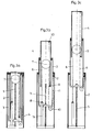
- a telescoping lifting column according to the invention comprises an outer lifting cylinder 2 concentrically held in this and axially displaceable from the position shown in FIG. 1 upwardly extendable middle lifting cylinder 3 and another concentrically held in the middle lifting cylinder 3 and axially displaceable in this guided inner lifting cylinder 4, which in turn from the middle lifting cylinder from the position shown in FIG. 1 can be moved upwards, so that a telescoping arrangement with the 3 lifting cylinders, namely the outer Lifting cylinder 2, the middle lifting cylinder 3 and the inner lifting cylinder 4 results.
- the lifting drive which is intended to drive out the middle lifting cylinder 3 from the outer lifting cylinder 2, is formed via a centrally arranged in the embodiment of the lifting spindle 5, which is driven for example by a recognizable in Fig. 2 electric motor 14.
- This lifting spindle engages in the lower region of the middle lifting cylinder 3, acts together with a spindle nut and drives the middle lifting cylinder 3 upon rotation in a drive direction upwards into a position, as can be seen for example in Fig. 3b.
- a tension member in the form of a chain 6 is provided, on the one hand in the lower region of the inner lifting cylinder. 4 is secured on the inside and that at the attachment point 9, which can be seen in Fig. 1 and also in Fig. 3b. Starting from there, this chain 6 is guided over a deflecting roller 7 located further upwards and deflected there by 180 ° and is then fixed at its other lower end to the attachment point 8, which can be seen in FIG.
- FIG. 3b which moves the inner lifting cylinder 4 synchronously downwards
- another tension member is for example in the form of a cable pull 11 provided, which also has a Guide roller 10 is guided and is deflected by 180 ° there, as can be seen from Fig. 3b in conjunction with Fig. 2.
- the position of this second lower guide roller 10 is, as seen in Fig. 2, off-center in the outer region in such a way that the guide roller 10 is located in the central vertical section of FIG. 1 behind the lifting spindle 5, so that it is not recognizable there , Furthermore, the lower guide roller 10 is located below the lower end of the middle lifting cylinder 3, as can be seen in Fig. 3b.
- This cable 11, which is guided over this lower guide roller 10, is now attached at its one end to the attachment point 12, which can be seen in Fig. 3b in the upper region attached to the outer lifting cylinder 2.
- the cable 11 is fixed to the inner lifting cylinder 4 after deflection at the deflection roller 10 by 180 ° at the upper end in the inner region at the fixing point 13 recognizable in FIG. 3b. If the middle lifting cylinder 3 is now shut down when the lifting spindle 5 is reversed, then the deflection roller 10 moves downwards therewith and since the length of the cable pull 11 is fixed and this is fixed at its upper end to the outer lifting cylinder 2, the cable pulls 11 at the attachment point 13, the inner lifting cylinder 4 corresponding to the stroke of the middle lifting cylinder 3 down.
Landscapes
- Health & Medical Sciences (AREA)
- Nursing (AREA)
- Life Sciences & Earth Sciences (AREA)
- Animal Behavior & Ethology (AREA)
- General Health & Medical Sciences (AREA)
- Public Health (AREA)
- Veterinary Medicine (AREA)
- Invalid Beds And Related Equipment (AREA)
Claims (7)
- Dispositif de levage, de préférence pour le réglage en hauteur d'un lit de malade ou de soins, comportant une colonne télescopique de levage comprenant un vérin extérieur de levage (2), un vérin central de levage (3) pouvant sortir et disposé concentriquement dans celui-ci et un vérin intérieur de levage (4) maintenu à son tour concentriquement dans celui-ci et pouvant sortir axialement,
comportant une propulsion de levage (5) pour faire sortir le vérin central de levage (3) et le vérin intérieur de levage (4) du vérin extérieur de levage (2),
un premier élément de traction (6) qui est fixé par une de ses extrémités dans la zone inférieure du vérin intérieur de levage (4) et est fixé par son autre extrémité sur le vérin extérieur de levage (2),
de sorte qu'en cas d'actionnement de la propulsion de levage (5), le vérin intérieur de levage (4) parcourt respectivement le double de la course de levage de la propulsion de levage (5),
au moins un deuxième élément de traction (11) qui est fixé par une de ses extrémités sur le vérin extérieur de levage (2) et qui est fixé par son autre extrémité sur le vérin intérieur de levage (4), de sorte qu'en cas de mouvement vers le bas de la propulsion de levage (5), une force de traction est exercée sur le vérin intérieur de levage (4) par le deuxième élément de traction (11) tandis qu'en même temps, lors du mouvement vers le bas, la propulsion de levage (5) exerce une force sur le vérin central de levage (3), la propulsion de levage (5) étant une broche de levage et à cette broche de levage étant associé un écrou de levage qui est fixé dans la zone terminale inférieure du vérin central de levage (3),
caractérisé en ce
que le premier élément de traction (6) est dévié par au moins un premier cylindre d'inversion (7), que le deuxième élément de traction (11) est dévié par au moins un deuxième cylindre d'inversion (10) d'environ 180°,
que la broche de levage (5), lorsqu'une colonne de levage est rentrée, plonge dans le vérin intérieur de levage (4),
et que le premier cylindre d'inversion (7) pour le premier élément de traction (6) est disposé au centre du vérin intérieur de levage (4) et au dessus de la broche de levage (5) et est fixé sur le vérin central de levage (3). - Dispositif de levage selon la revendication 1, caractérisé en ce que le deuxième cylindre d'inversion (10) par lequel est guidé le deuxième élément de traction (11) est fixé sur le vérin central de levage (3).
- Dispositif de levage selon l'une quelconque des revendications 1 ou 2, caractérisé en ce que le deuxième cylindre d'inversion (10) pour le deuxième élément de traction (11) est fixé dans la zone terminale inférieure sur le vérin central de levage (3).
- Dispositif de levage selon l'une quelconque des revendications 1 à 3, caractérisé en ce que le deuxième élément de traction (11) est un câble ou similaire.
- Dispositif de levage selon l'une quelconque des revendications 1 à 4, caractérisé en ce que le premier élément de traction (6) est fixé dans la zone terminale inférieure à un point de fixation (9) sur le vérin intérieur de levage (4), ce premier élément de traction (6) étant guidé par le premier cylindre d'inversion (7) et y étant dévié d'environ 180° et ce premier élément de traction (6) étant fixé par son autre extrémité à une barre (15) qui est reliée fixement au vérin extérieur de levage (2).
- Dispositif de levage, de préférence pour lit de malade ou de soins, selon l'une quelconque des revendications 1 à 5, caractérisé en ce que le premier élément de traction (6) est une chaîne.
- Dispositif de levage, de préférence pour lit de malade ou de soins, selon l'une quelconque des revendications 1 à 6, caractérisé en ce que le deuxième cylindre d'inversion (10) pour le deuxième élément de traction (11) est disposé à l'extérieur du centre à proximité de la zone circonférentielle du vérin central de levage (3).
Applications Claiming Priority (2)
| Application Number | Priority Date | Filing Date | Title |
|---|---|---|---|
| DE1998138326 DE19838326A1 (de) | 1997-09-09 | 1998-08-24 | Hubvorrichtung vorzugsweise für die Höhenverstellung eines Kranken- oder Pflegebetts |
| DE19838326 | 1998-08-24 |
Publications (3)
| Publication Number | Publication Date |
|---|---|
| EP0982018A2 EP0982018A2 (fr) | 2000-03-01 |
| EP0982018A3 EP0982018A3 (fr) | 2000-11-15 |
| EP0982018B1 true EP0982018B1 (fr) | 2006-06-07 |
Family
ID=7878481
Family Applications (1)
| Application Number | Title | Priority Date | Filing Date |
|---|---|---|---|
| EP99100434A Expired - Lifetime EP0982018B1 (fr) | 1998-08-24 | 1999-01-11 | Dispositif de levage de préfèrence pour le réglage en hauteur de lits de malades ou de soins |
Country Status (3)
| Country | Link |
|---|---|
| EP (1) | EP0982018B1 (fr) |
| AT (1) | ATE328563T1 (fr) |
| DE (1) | DE59913506D1 (fr) |
Cited By (8)
| Publication number | Priority date | Publication date | Assignee | Title |
|---|---|---|---|---|
| JP2009191987A (ja) * | 2008-02-15 | 2009-08-27 | Hiwin Mikrosystem Corp | リニアアクチュエータ |
| JP2009191989A (ja) * | 2008-02-15 | 2009-08-27 | Hiwin Mikrosystem Corp | リニアアクチュエータ |
| JP2009191988A (ja) * | 2008-02-15 | 2009-08-27 | Hiwin Mikrosystem Corp | リニアアクチュエータ |
| DE102008000666B3 (de) * | 2008-03-13 | 2010-01-28 | Hiwin Mikrosystem Corp. | Linearantrieb |
| US7752932B2 (en) | 2008-04-06 | 2010-07-13 | Hiwin Mikrosystem Corp. | Linear actuator |
| US8074309B2 (en) | 2009-03-04 | 2011-12-13 | Hill-Rom Services, Inc. | Height adjustable bed with a lift chain assembly and components thereof |
| US8104120B2 (en) | 2010-02-18 | 2012-01-31 | Hill-Rom Services, Inc. | Height adjustable bed with a push chain assembly |
| WO2021093922A1 (fr) | 2019-11-13 | 2021-05-20 | Linak A/S | Colonne élévatrice |
Families Citing this family (10)
| Publication number | Priority date | Publication date | Assignee | Title |
|---|---|---|---|---|
| EP1686943A1 (fr) * | 2003-11-18 | 2006-08-09 | Linak A/S | Lit d'hopital ou de soins |
| WO2006053559A2 (fr) | 2004-11-17 | 2006-05-26 | Linak A/S | Actionneur lineaire |
| CZ16500U1 (cs) * | 2006-03-31 | 2006-05-11 | Linet, Spol. S R. O. | Teleskopický zvedák, zejména pro výskové prestavení nemocnicního luzka |
| JP5236734B2 (ja) * | 2007-09-13 | 2013-07-17 | リナック エー/エス | 治療台、病院用ベッド、および介護用ベッドのための昇降支柱 |
| DE102011004337A1 (de) * | 2011-02-17 | 2012-08-23 | Schaeffler Technologies Gmbh & Co. Kg | Hubelement |
| DE202016107514U1 (de) * | 2016-12-30 | 2018-04-05 | Wissner-Bosserhoff Gmbh | Anordnung zur Sicherung eines Bettinsassen gegen ein Herausfallen aus einem Bett, insbesondere einem Pflegebett, und Bett, insbesondere Pflegebett mit einer Sicherungsanordnung |
| US11007638B2 (en) * | 2018-12-20 | 2021-05-18 | Honda Motor Co., Ltd. | Telescoping support robot and methods of use thereof |
| CN110017886A (zh) * | 2019-05-22 | 2019-07-16 | 成都大学附属医院 | 一种滚轮式体重秤 |
| CN110953315A (zh) * | 2019-12-27 | 2020-04-03 | 福州大学 | 一种行程倍增的双机械手同步升降机构及其工作方法 |
| CN114392114A (zh) * | 2022-02-15 | 2022-04-26 | 昆霖科技(深圳)有限公司 | 牙科治疗椅升降结构 |
Family Cites Families (5)
| Publication number | Priority date | Publication date | Assignee | Title |
|---|---|---|---|---|
| US1700741A (en) * | 1926-05-17 | 1929-02-05 | Ritter Dental Mfg Company Inc | Extensible chair |
| BE899228A (nl) * | 1984-03-23 | 1984-07-16 | Tecnomatix N V | Telescoop voor een portaalrobot en andere. |
| DE8523224U1 (de) * | 1985-08-13 | 1986-01-16 | Bosserhoff, Gerd, 4795 Delbrück | Krankenbett |
| CH670899A5 (en) * | 1986-09-04 | 1989-07-14 | Peter Huerlimann | Telescopic camera stand with motorised drive - has carbon fibre bands for drive to successive telescopic sections |
| DE19528179B4 (de) * | 1995-08-01 | 2004-04-22 | Vauth-Sagel GmbH & Co. Grundstücksverwaltung | Kranken- oder Pflegebett |
-
1999
- 1999-01-11 AT AT99100434T patent/ATE328563T1/de not_active IP Right Cessation
- 1999-01-11 EP EP99100434A patent/EP0982018B1/fr not_active Expired - Lifetime
- 1999-01-11 DE DE59913506T patent/DE59913506D1/de not_active Expired - Lifetime
Cited By (8)
| Publication number | Priority date | Publication date | Assignee | Title |
|---|---|---|---|---|
| JP2009191987A (ja) * | 2008-02-15 | 2009-08-27 | Hiwin Mikrosystem Corp | リニアアクチュエータ |
| JP2009191989A (ja) * | 2008-02-15 | 2009-08-27 | Hiwin Mikrosystem Corp | リニアアクチュエータ |
| JP2009191988A (ja) * | 2008-02-15 | 2009-08-27 | Hiwin Mikrosystem Corp | リニアアクチュエータ |
| DE102008000666B3 (de) * | 2008-03-13 | 2010-01-28 | Hiwin Mikrosystem Corp. | Linearantrieb |
| US7752932B2 (en) | 2008-04-06 | 2010-07-13 | Hiwin Mikrosystem Corp. | Linear actuator |
| US8074309B2 (en) | 2009-03-04 | 2011-12-13 | Hill-Rom Services, Inc. | Height adjustable bed with a lift chain assembly and components thereof |
| US8104120B2 (en) | 2010-02-18 | 2012-01-31 | Hill-Rom Services, Inc. | Height adjustable bed with a push chain assembly |
| WO2021093922A1 (fr) | 2019-11-13 | 2021-05-20 | Linak A/S | Colonne élévatrice |
Also Published As
| Publication number | Publication date |
|---|---|
| DE59913506D1 (de) | 2006-07-20 |
| EP0982018A2 (fr) | 2000-03-01 |
| EP0982018A3 (fr) | 2000-11-15 |
| ATE328563T1 (de) | 2006-06-15 |
Similar Documents
| Publication | Publication Date | Title |
|---|---|---|
| EP0982018B1 (fr) | Dispositif de levage de préfèrence pour le réglage en hauteur de lits de malades ou de soins | |
| EP2152120A1 (fr) | Colonne réglable en hauteur, en particulier pour tables | |
| EP2974623A1 (fr) | Dispositif d'appui reglable a moteur electrique | |
| WO2000056259A1 (fr) | Lit pour malade et/ou d'infirmerie et element support reglable en longueur pour ce lit | |
| DE3415930A1 (de) | Kraftfahrzeugfensterrollo | |
| EP2878230A1 (fr) | Mécanisme de fixation à leviers doté de câble Bowden | |
| EP1584264B1 (fr) | Système d'entrainement réglable en hauteur notamment pour meubles | |
| EP3009052A1 (fr) | Dispositif de réglage à moteur électrique | |
| EP3620425A1 (fr) | Ascenseur déplaçable pour personnes | |
| EP3354817B1 (fr) | Store comprenant des supports verticaux modifiables en longueur et palier coulissant latéral | |
| EP0733021B1 (fr) | Fleche telescopique a verin hydraulique a plusieurs etages | |
| EP3771600A1 (fr) | Manivelle pour une béquille | |
| DE4105482A1 (de) | Schwenktuere fuer kundenfuehrungsanlagen | |
| EP0496994B1 (fr) | Support | |
| DE19838326A1 (de) | Hubvorrichtung vorzugsweise für die Höhenverstellung eines Kranken- oder Pflegebetts | |
| EP0736642A1 (fr) | Marquise avec moyens de tension élastiques | |
| DE102017127700A1 (de) | Hubaggregat | |
| DE10216774A1 (de) | Höhenverstellbarer Tisch | |
| EP2325429A2 (fr) | Entraînement de capote | |
| DE2318993A1 (de) | Teleskopierbarer ausleger oder druckstempel mit rueckholung | |
| EP1543744B1 (fr) | Dispositif de levage pour lits | |
| EP3738462A1 (fr) | Parapluie bras libre, en particulier pour la protection contre le soleil et la pluie | |
| CH707352A2 (de) | Teleskopierbarer Spindelantrieb und Tischmöbel mit einem teleskopierbaren Spindelantrieb. | |
| DE102007057113A1 (de) | Hubsäulen-Antrieb | |
| EP0040289B1 (fr) | Dispositif tendeur pour convoyeur vertical, notamment pour transporteur à godets |
Legal Events
| Date | Code | Title | Description |
|---|---|---|---|
| PUAI | Public reference made under article 153(3) epc to a published international application that has entered the european phase |
Free format text: ORIGINAL CODE: 0009012 |
|
| AK | Designated contracting states |
Kind code of ref document: A2 Designated state(s): AT CH DE FR GB IT LI NL |
|
| AX | Request for extension of the european patent |
Free format text: AL;LT;LV;MK;RO;SI |
|
| PUAL | Search report despatched |
Free format text: ORIGINAL CODE: 0009013 |
|
| AK | Designated contracting states |
Kind code of ref document: A3 Designated state(s): AT BE CH CY DE DK ES FI FR GB GR IE IT LI LU MC NL PT SE |
|
| AX | Request for extension of the european patent |
Free format text: AL;LT;LV;MK;RO;SI |
|
| 17P | Request for examination filed |
Effective date: 20010515 |
|
| AKX | Designation fees paid |
Free format text: AT CH DE FR GB IT LI NL |
|
| 17Q | First examination report despatched |
Effective date: 20041222 |
|
| GRAP | Despatch of communication of intention to grant a patent |
Free format text: ORIGINAL CODE: EPIDOSNIGR1 |
|
| GRAS | Grant fee paid |
Free format text: ORIGINAL CODE: EPIDOSNIGR3 |
|
| GRAA | (expected) grant |
Free format text: ORIGINAL CODE: 0009210 |
|
| AK | Designated contracting states |
Kind code of ref document: B1 Designated state(s): AT CH DE FR GB IT LI NL |
|
| PG25 | Lapsed in a contracting state [announced via postgrant information from national office to epo] |
Ref country code: IT Free format text: LAPSE BECAUSE OF FAILURE TO SUBMIT A TRANSLATION OF THE DESCRIPTION OR TO PAY THE FEE WITHIN THE PRESCRIBED TIME-LIMIT;WARNING: LAPSES OF ITALIAN PATENTS WITH EFFECTIVE DATE BEFORE 2007 MAY HAVE OCCURRED AT ANY TIME BEFORE 2007. THE CORRECT EFFECTIVE DATE MAY BE DIFFERENT FROM THE ONE RECORDED. Effective date: 20060607 |
|
| REG | Reference to a national code |
Ref country code: GB Ref legal event code: FG4D Free format text: NOT ENGLISH |
|
| REG | Reference to a national code |
Ref country code: CH Ref legal event code: EP |
|
| REF | Corresponds to: |
Ref document number: 59913506 Country of ref document: DE Date of ref document: 20060720 Kind code of ref document: P |
|
| GBT | Gb: translation of ep patent filed (gb section 77(6)(a)/1977) |
Effective date: 20060927 |
|
| ET | Fr: translation filed | ||
| PG25 | Lapsed in a contracting state [announced via postgrant information from national office to epo] |
Ref country code: LI Free format text: LAPSE BECAUSE OF NON-PAYMENT OF DUE FEES Effective date: 20070131 Ref country code: CH Free format text: LAPSE BECAUSE OF NON-PAYMENT OF DUE FEES Effective date: 20070131 |
|
| PLBI | Opposition filed |
Free format text: ORIGINAL CODE: 0009260 |
|
| 26 | Opposition filed |
Opponent name: LINAK A/S Effective date: 20070306 |
|
| PLAX | Notice of opposition and request to file observation + time limit sent |
Free format text: ORIGINAL CODE: EPIDOSNOBS2 |
|
| NLR1 | Nl: opposition has been filed with the epo |
Opponent name: LINAK A/S |
|
| REG | Reference to a national code |
Ref country code: CH Ref legal event code: PL |
|
| PLBB | Reply of patent proprietor to notice(s) of opposition received |
Free format text: ORIGINAL CODE: EPIDOSNOBS3 |
|
| PG25 | Lapsed in a contracting state [announced via postgrant information from national office to epo] |
Ref country code: AT Free format text: LAPSE BECAUSE OF NON-PAYMENT OF DUE FEES Effective date: 20070111 |
|
| PLCK | Communication despatched that opposition was rejected |
Free format text: ORIGINAL CODE: EPIDOSNREJ1 |
|
| APBM | Appeal reference recorded |
Free format text: ORIGINAL CODE: EPIDOSNREFNO |
|
| APBP | Date of receipt of notice of appeal recorded |
Free format text: ORIGINAL CODE: EPIDOSNNOA2O |
|
| APAH | Appeal reference modified |
Free format text: ORIGINAL CODE: EPIDOSCREFNO |
|
| APBU | Appeal procedure closed |
Free format text: ORIGINAL CODE: EPIDOSNNOA9O |
|
| PLBN | Opposition rejected |
Free format text: ORIGINAL CODE: 0009273 |
|
| STAA | Information on the status of an ep patent application or granted ep patent |
Free format text: STATUS: OPPOSITION REJECTED |
|
| 27O | Opposition rejected |
Effective date: 20081111 |
|
| NLR2 | Nl: decision of opposition |
Effective date: 20081111 |
|
| REG | Reference to a national code |
Ref country code: FR Ref legal event code: PLFP Year of fee payment: 18 |
|
| REG | Reference to a national code |
Ref country code: FR Ref legal event code: PLFP Year of fee payment: 19 |
|
| REG | Reference to a national code |
Ref country code: FR Ref legal event code: PLFP Year of fee payment: 20 |
|
| PGFP | Annual fee paid to national office [announced via postgrant information from national office to epo] |
Ref country code: NL Payment date: 20180119 Year of fee payment: 20 |
|
| PGFP | Annual fee paid to national office [announced via postgrant information from national office to epo] |
Ref country code: GB Payment date: 20180119 Year of fee payment: 20 Ref country code: DE Payment date: 20180131 Year of fee payment: 20 |
|
| PGFP | Annual fee paid to national office [announced via postgrant information from national office to epo] |
Ref country code: FR Payment date: 20180119 Year of fee payment: 20 Ref country code: IT Payment date: 20180129 Year of fee payment: 20 |
|
| REG | Reference to a national code |
Ref country code: DE Ref legal event code: R071 Ref document number: 59913506 Country of ref document: DE |
|
| REG | Reference to a national code |
Ref country code: NL Ref legal event code: MK Effective date: 20190110 |
|
| REG | Reference to a national code |
Ref country code: GB Ref legal event code: PE20 Expiry date: 20190110 |
|
| PG25 | Lapsed in a contracting state [announced via postgrant information from national office to epo] |
Ref country code: GB Free format text: LAPSE BECAUSE OF EXPIRATION OF PROTECTION Effective date: 20190110 |