US8074309B2 - Height adjustable bed with a lift chain assembly and components thereof - Google Patents
Height adjustable bed with a lift chain assembly and components thereof Download PDFInfo
- Publication number
- US8074309B2 US8074309B2 US12/397,511 US39751109A US8074309B2 US 8074309 B2 US8074309 B2 US 8074309B2 US 39751109 A US39751109 A US 39751109A US 8074309 B2 US8074309 B2 US 8074309B2
- Authority
- US
- United States
- Prior art keywords
- bed
- magazine
- frame
- segment
- chain
- Prior art date
- Legal status (The legal status is an assumption and is not a legal conclusion. Google has not performed a legal analysis and makes no representation as to the accuracy of the status listed.)
- Active, expires
Links
Images


Classifications
-
- A—HUMAN NECESSITIES
- A61—MEDICAL OR VETERINARY SCIENCE; HYGIENE
- A61G—TRANSPORT, PERSONAL CONVEYANCES, OR ACCOMMODATION SPECIALLY ADAPTED FOR PATIENTS OR DISABLED PERSONS; OPERATING TABLES OR CHAIRS; CHAIRS FOR DENTISTRY; FUNERAL DEVICES
- A61G7/00—Beds specially adapted for nursing; Devices for lifting patients or disabled persons
- A61G7/002—Beds specially adapted for nursing; Devices for lifting patients or disabled persons having adjustable mattress frame
- A61G7/012—Beds specially adapted for nursing; Devices for lifting patients or disabled persons having adjustable mattress frame raising or lowering of the whole mattress frame
-
- B—PERFORMING OPERATIONS; TRANSPORTING
- B66—HOISTING; LIFTING; HAULING
- B66F—HOISTING, LIFTING, HAULING OR PUSHING, NOT OTHERWISE PROVIDED FOR, e.g. DEVICES WHICH APPLY A LIFTING OR PUSHING FORCE DIRECTLY TO THE SURFACE OF A LOAD
- B66F3/00—Devices, e.g. jacks, adapted for uninterrupted lifting of loads
- B66F3/02—Devices, e.g. jacks, adapted for uninterrupted lifting of loads with racks actuated by pinions
- B66F3/06—Devices, e.g. jacks, adapted for uninterrupted lifting of loads with racks actuated by pinions with racks comprising pivotable toothed sections or segments, e.g. arranged in pairs
Definitions
- the subject matter described herein relates to height adjustable beds and particularly to a bed whose height adjustment system employs a lift chain assembly.
- Lift systems used in health care facilities and home care settings often include a lift system allowing a patient or caregiver to adjust the height of the bed.
- the lift system must satisfy a number of potentially conflicting constraints.
- the lift system should be quiet, dependable, safe and damage resistant. It should also be inexpensive to manufacture and should be adaptable to different bed models with no more than simple, inexpensive modifications. Because the lift system typically resides underneath the elevateable components of the bed, it must be compact enough to allow the bed to be positioned at very low elevations and yet must also have enough reach to position the bed at elevations high enough to be satisfactory for the caregiver. Compactness also makes space available for other under-bed components.
- a bed as disclosed herein has a base frame, an elevateable frame and at least one telescopable column. Each column circumscribes a lift chain assembly which includes a magazine and a lift chain with a terminal link.
- the magazine is connected to either the base frame or the elevateable frame and the terminal link is connected to the other of the base frame and the elevateable frame.
- the magazine comprises left and right magazine covers each having an outer face and an inner face with grooves.
- the lift chain has left and right rollers that project into the grooves.
- the lift assembly also includes a gear train extending from a gear train drive shaft to a gear train output shaft and a motor having an output shaft connected to the gear train drive shaft.
- the lift chain is made of left, right and medial link arrays comprised of left, right and medial links that are substantially identical to each other. Longitudinally opposite ends of the links are configured so that the chain resists bending about a lateral axis in one of two opposite rotational directions.
- a terminal link is connected to one extremity of the chain so that the center of action of the link is transversely offset from the chain meanline in a direction that would urge the chain to bend in the bend resistant direction.
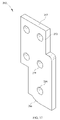
- a link for the lift chain is a flat plate having a simple end and a compound end.
- the simple end includes a first convex circular arc and a ledge that form a first angle of less than 180 degrees.
- the compound end includes a second convex circular arc, a concave circular arc and a tooth with a crown. The concave arc and the crown form a second angle of no more than about 90 degrees.
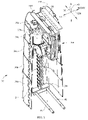
- FIG. 1 is a perspective view of the framework of a height adjustable bed having two canister assemblies defining telescoping columns, each of which circumscribes a lift chain assembly, not visible, for changing the height of an elevateable portion of the framework.
- FIG. 2 is a view similar to FIG. 1 with the telescoping columns broken away to reveal the lift chain assemblies.
- FIG. 3 is an enlarged view of one of the telescoping columns of FIG. 2 .
- FIG. 4 is a side elevation view of the bed of FIGS. 1 and 2 .
- FIG. 5 is a perspective views of the upper portions of the head end canister assembly showing hinge pins allowing the head end of the elevateable frame to pivot relative to the canister.
- FIG. 6 is a perspective view of the upper portions of the foot end canister assembly showing hinge pins allowing the foot end of the elevateable frame to pivot relative to the canister and also showing slider blocks trapped in a track for allowing translation of the elevateable frame relative to the canister assembly.
- FIG. 7 is a perspective view of a lift chain assembly partially exploded to show components of a gear train.
- FIGS. 8 and 9 are exploded perspective views of the lift chain assembly as seen by observers looking in opposite directions.
- FIGS. 10 and 11 are a perspective view and a side elevation view of a chain used in the lift chain assembly as the chain would appear if partially extended from the lift chain assembly.
- FIG. 12 is a perspective view similar to that of FIG. 9 showing the chain as it would appear if retracted into and coiled up inside the lift chain assembly.
- FIGS. 13 and 14 are exploded perspective views of the chain as seen by observers looking in opposite directions.
- FIGS. 15 and 16 are a side elevation view and a perspective view of a representative link of the chain.
- FIG. 17 is a side elevation view of a medial terminal link of the chain.
- FIG. 18 is a perspective view of a portion of the lift chain assembly showing a switch and a switch contact element for limiting extension and retraction of the chain.
- FIGS. 1-4 show components of a hospital bed 14 with a lift system as described herein.
- the bed has a head end 16 , a foot end, 18 a left side 20 and a right side 22 .
- the illustration also depicts longitudinal, lateral and vertical directional axes 24 , 26 , 28 .
- the bed includes a base frame 32 , an elevateable frame 34 and a pair of canister assemblies 36 each comprising two or more canister segments.
- the illustrated embodiment has a bottom-most or base canister segment 36 a , three intermediate segments 36 b , 36 c , 36 d and an upper-most or terminal segment 36 e fitted together to define head end and foot end telescopable columns 36 .
- Each canister segment comprises two semi-segments joined together along two dovetail seams 42 .
- the upper-most or terminal segment 36 e of each column includes an upper cover plate 44 at its vertically upper end.
- the bottom-most or base segment 36 a of each column includes laterally extending mounting bars 46 joined to the base segment. The bars extend through and are secured to a mounting block 48 near one lateral side of the segment.
- the mounting block 48 serves as a mounting location for a chain as described more completely hereinafter. Alternatively, the mounting location could be a plate similar to cover plate 44 .
- Each base segment 36 a is securely connected to the base frame by brackets 50 or in any other suitable way to anchor the base segment to the base frame.
- a head end crossbar 52 is secured to the terminal segment 36 e of the head end column.
- Left and right hinge pins 54 connect the head end of the elevateable frame 34 to the crossbar to provide for pivotal motion therebetween about axis 56 .
- a foot end crossbar 58 is secured to the terminal segment 36 e of the foot end column.
- Left and right hinge pins 60 connect the crossbar 58 to respective left and right slider blocks 62 .
- the slider blocks are trapped in a track 64 at the foot end of the elevateable frame 34 , but can slide longitudinally in the track.
- the hinge thus formed provides for pivotal motion of the elevateable frame relative to the crossbar about a longitudinally translatable pivot axis 66 .
- the rotational freedom at the head end in combination with the rotational and translational freedom at the foot end, allows the columns to be telescoped to different heights to place the upper frame at a positive or negative pitch orientation ⁇ ( FIG. 3 ) relative to horizontal.
- Other mechanical arrangements could also be used to achieve the angular orientation ⁇ .
- each column is non-rotationally secured to the base frame by the brackets 50 .
- the segment 36 a is secured to the base frame in a way that allows the segment 36 a , and therefore the entire column and the elevateable frame, to pivot about a longitudinally extending pivot axis 70 ( FIGS. 1 and 2 ).
- each telescopable column 36 circumscribes a lift chain assembly 100 .
- Each lift chain assembly includes a magazine 102 comprised of magazine covers 104 , 106 .
- Each cover has a mounting flange 108 , an outer face 112 and an inner face 114 .
- the covers are secured together by five bolts 116 but spaced from each other to define an inter-cover space 118 .
- the inner faces 114 each include a coil shaped groove 120 having a terminal leg 122 seen best in FIGS. 8 and 9 .
- the groove has a laterally deeper trench portion 121 ( FIG. 18 ).
- the covers, including one end of each groove cooperate with each other to define a window 124 .
- Each cover includes a low friction bushing 126 .
- a coupler 128 nests in the bushings and is rotatable relative thereto. As seen best in FIG. 9 , the coupler has an input side 132 and an output side 134 .
- the covers 104 , 106 are referred to as laterally left and right covers even though in the illustrated embodiment they are oriented at 90 degrees to the left and right (lateral) direction 26 depicted on FIG. 1 for describing the bed as a whole.
- the local longitudinal direction 138 is the direction parallel to the planes defined by the inner faces 114 of the magazine covers.
- the local vertical or transverse direction 140 is a direction mutually perpendicular to the local lateral and longitudinal directions and is the same as the vertical direction of FIG. 1 . It should be appreciated that the name of the directional axes are chosen for convenience in referring to the Figures and in no way constrain the actual orientation of the lift chain assembly relative to the other components of the bed.
- the lift chain assembly also includes a chain 160 retractable into and extendible out of the magazine.
- the chain is made of left, right and medial chain link arrays 162 , 164 , 166 each comprised of respective left, right and medial links 168 , 170 , 172 . Except for terminal links described below, all the links are substantially identical and are in the form of small flat plates as seen in FIGS. 15-16 having a length L, a width W and a thickness T.
- Each link has a simple end 174 and a compound end 176 .
- the simple end of a representative link includes a convex circular arc 180 and a ledge 182 .
- the ledge and a line 184 tangent to the arc at the juncture of the ledge and the arc form an angle ⁇ of less than 180 degrees.
- the arc 180 has a center C S on the lengthwise meanline 186 of the link
- the compound end 176 of a representative link includes a convex circular arc 200 , a concave circular arc 202 and a tooth 204 with a crown 206 .
- One end of concave arc 202 blends with an end of convex arc 200 .
- a line 210 tangent to the concave arc 202 at the juncture of the arc and the crown 206 forms an angle ⁇ of no more than about 90 degrees with the crown.
- the arc 200 has a center C C on the lengthwise meanline 186 of the link. Holes 212 , 214 centered on arc centers C S , C C penetrate through each link.
- the chain also includes link connector pins 230 having a head 233 and a shank 234 ( FIG. 14 ). The end of the shank remote from the head is deformable.
- Each pin 230 extends laterally through the holes 212 , 214 and through a pair of rollers 238 to pivotably connect the links together so that the medial link array 166 laterally abuts the left and right link arrays 162 , 164 and so that the links of the medial array are lengthwisely offset from the links of the left and right arrays by one-half pitch, where pitch is the lengthwise distance P ( FIGS. 11 and 13 ) from a feature on the chain to the next adjacent occurrence of the same feature (e.g. between successive occurrences of holes 212 ).
- the lengthwise meanlines 186 of the individual links define a chain meanline 232 FIG. 11 .
- the configuration of the link ends allows the chain to flex about a laterally extending axis in only one of two opposite directions and to resist flexing in the other of the two directions.
- contact between the ledge 182 of one link and the tooth crown 206 of the neighboring link, along with the interaction of the circular arcs 180 , 202 prohibits the chain from flexing in rotational sense S L (e.g. about an axis L).
- circular arc 180 is able to roll relative to circular arc 200 thereby allowing the chain to flex in rotational sense S R (e.g. about an axis R).
- each pin carries a pair of rollers 238 .
- the head of the pin traps one roller of the pair, e.g. the right roller, against a right link.
- the other end of the pin is deformed so that it traps the other roller against the opposite (e.g. left) link.
- the rollers 238 project laterally into the grooves 120 in the magazine covers 104 , 106 to support the chain and cause it to coil inside the magazine when the chain is retracted.
- the chain also includes left and right outboard terminal links 240 each having a leg portion 242 and a foot portion 244 which serves as a mounting flange.
- each outboard terminal link has a simple profile comprising a circular arc 252 and a ledge 254 not unlike the circular arc 180 and ledge 182 of links 168 , 170 , 172 except that the arc 252 subtends a smaller angle.
- Holes 256 , 258 FIGS. 13-14 ) penetrate through the leg to accommodate connector pins 230 Hole 256 is centered on the center of the circular arc 252 .
- the chain also includes a medial or inboard terminal link 262 seen best in FIG. 17 .
- One end 264 of the medial terminal link is squared off.
- the other end 266 has a profile similar to that of the simple end 174 of a link 168 , 170 , 172 thereby allowing that end 266 to engage the compound end 176 of the adjacent medial link.
- Holes 268 , 270 , 272 penetrate the medial terminal link.
- Connector pins 230 of the type already described are used to attach the terminal links to each other and to the outboard non-terminal links 168 , 170 at one end of the chain.
- one of the pins 230 designated as 230 a , extends through holes 214 in a pair of outboard, non-terminal links 168 , 170 and through hole 268 in the medial terminal link 262 .
- Pin designated 230 b extends through holes 256 in the outboard terminal links and through hole 270 in the medial terminal link.
- Pin designated 230 c extends through holes 258 in the outboard terminal links and through hole 272 in the medial terminal link.
- a pin 231 extends through the holes 212 of the outboard links most remote from the terminal links. As seen best in FIG. 18 , pin 231 is laterally longer than pins 230 so that the ends of the pin extend past the rollers 238 and into the trench portion 121 of each groove 120 .
- a contact element 127 of a retraction stop switch 129 ( FIG. 18 ) and an extension stop switch 130 ( FIGS. 7 and 9 ) also project into the trench. The switches are electrically connected to the motor to limit extension and retraction of the chain as described below.
- the lift chain assembly also includes an electric motor 278 and gearbox 280 assembly and a mounting plate 282 with motor mount bolt holes 284 .
- the motor and mounting plate are secured to each other by motor mount bolts 286 extending through the holes 284 from the unexposed side of the mounting plate and into motor mount sockets 288 in the motor and gearbox assembly.
- the mounting plate 282 is secured to magazine cover 104 by plate mounting bolts 302 (not all of which are visible) extending through plate holes 304 and into bolt holes 306 (some of which are visible in FIG. 9 ) in the magazine cover 104 .
- the motor has a primary shaft, not visible, rotatable about axis 312 .
- Gearbox 280 attached to one end of the motor includes gears that mesh with a worm on the primary shaft to convey the torque and rotary motion of the primary shaft to a motor output shaft 314 oriented 90 degrees to the primary shaft.
- the motor output shaft has a spline drive 316 at its tip, although other configurations, such as square and hex drives, could also be used.
- the spline drive mates with the input side 132 of coupler 128 .
- the lift chain assembly also includes a gear train 320 having a pinion 322 , a combination gear 324 , an idler 328 and a driving gear 330 .
- the gears reside between the magazine cover 106 and a gear train cover 332 secured to the magazine cover.
- a pinion drive shaft 334 which serves as a gear train drive shaft, extends from pinion and into the output side 134 of the coupler 128 to connect the pinion to the coupler.
- the pinion and stacked gear 324 effect a speed reduction of about 3.5:1.
- the stacked gear and the idler 328 effect another speed reduction of about 3.5:1.
- the driving gear 330 is mounted on a gear train output shaft or sprocket shaft 338 .
- the sprocket shaft is non-coaxial with the pinion drive shaft 334 and is operatively connected to the lift chain by left and right sprockets 340 ( FIG. 9 ) also mounted on the sprocket shaft in the space between the magazine covers.
- the teeth of the sprockets engage the chain rollers 238 near the outboard flanks of the left and right chain arrays.
- the illustrated bed 14 includes two of the above described lift chain assemblies, each circumscribed by one of the telescopable columns 36 .
- the mounting flanges 108 of the magazine are secured to the interior surface of upper segment cover plate 44 ; the feet 244 of the outboard terminal links 240 are secured to the mounting block 48 ( FIGS. 2-3 ).
- the feet may be secured to a lower segment mounting cover similar to upper cover plate 44 if such a cover is provided.
- the orientation of the entire lift chain assembly could be reversed (accompanied by appropriate changes to the mounting arrangements) so that the magazine flanges 108 are vertically lower than the feet 244 rather than vertically higher than the feet. As seen in FIG.
- the head end lift chain assembly is oriented so that the lift chain 160 emerges from the magazine closer to the right side of its telescoping column.
- the lift chain of the foot end lift chain assembly emerges from its magazine closer the left side of its telescoping column.
- the mounting feet 244 are equidistantly and oppositely offset by a distance d from the longitudinal centerplane (the plane defined by axes 24 , 28 ) of the bed. Non-equidistant offsets may also be used if desired.
- the mounting flanges 108 of the magazine although directly connected to the interior surface of upper segment cover plate 44 , are indirectly connected to the elevateable frame 34 by way of crossbar 52 or 58 .
- the feet 244 of the outboard terminal links 240 although directly secured to the mounting block 48 , are indirectly connected to the base frame 32 by way of the mounting bars 46 , base segment 36 a and brackets 50 .
- the mounting flanges 108 and feet 244 may each be connected directly to one of the frames rather than indirectly by way of intermediate components.
- An operator's switch is used by an operator to operate the lift system.
- the switch has “extend”, “off” and “retract” positions.
- the torque and rotary motion of the motor are conveyed to the sprockets by way of the motor output shaft 314 , the gear train 320 , and the sprocket shaft 338 .
- the motor is rotated in an “extend” direction the sprockets push the chain causing the rollers, and therefore the entire chain, to move along the grooves 120 in the magazine covers.
- the terminal leg 122 of the groove guides the chain into a linear shape as seen at the left side of FIGS. 10-11 .
- the chain progressively exits the magazine by way of the window 124 ( FIG.
- the sprockets push the chain in the opposite direction, once again causing the rollers, and therefore the entire chain, to move along the grooves 120 in the magazine covers.
- the chain progressively enters the magazine by way of the window 124 , thereby moving the magazine vertically downwardly, collapsing the telescoping column, and lowering the elevateable bed frame.
- the linear portion of the chain continues to support the loads applied to the chain.
- the portion of the chain inside the magazine is free to flex as necessary in the direction that allows the chain to follow the shape of the groove 120 and to coil up inside the magazine thereby minimizing the amount of space required to house it.
- Such operation continues until the operator moves the operator's switch off the “retract” position or until pin 231 acts on the retraction stop switch 129 .
- the system can, of course, be used to elevate the head and foot ends of the bed unequally to place the elevateable frame in a positive (head up) or a negative (head down) angular orientation ⁇ as seen in FIG. 4 .
- the column segments 36 a - 36 e resist rotation relative to each other about a vertical axis 344 extending through the interior of the column.
- Rotational resistance may be imparted easily and inexpensively by employing segments having a non-circular shape when viewed in the vertical direction.
- the specific variant shown in the illustrations is approximately rectangular with rounded corners.
- the feet of the terminal links have a center of loading 346 offset from the meanline 232 of the erect portion of the chain by a distance D.
- the offset imposes a moment on the aligned links.
- the direction of the offset is chosen so that the sense of the resulting moment is in the flex-resistant direction of the chain i.e. in direction S L . If the load were centered on the chain meanline 232 , the aligned links would be susceptible to collective flexure.
- gear train 320 allows the designer to use an inexpensive, off the shelf motor whose torque-speed characteristics differ from those required at the sprocket. Without the gear train, the designer may find it necessary to bear the expense of designing a custom made motor and having it manufactured.
- the links are identical, the only exceptions being the outboard terminal links 240 and the medial or inboard terminal link 262 .
- the non-terminal links 168 , 170 , 172 are simple in design and therefore easy to manufacture. The link identicality and ease of manufacture contribute to low cost manufacture.
- the compression chain unit is also compact enough to fit comfortably in the confined space underneath the elevateable deck frame, a space that becomes increasingly confined as the elevateable frame is lowered. As a result of the compactness, the elevateable frame can be lowered to a particularly low elevation, which improves the clinical attractiveness of the bed.
- the motor and mounting plate are secured to each other by motor mount bolts 286 extending through motor mount holes 284 .
- the mounting plate with the motor/gearbox assembly attached thereto as just described, is secured to one of the magazine covers by plate mounting bolts 302 extending through the plate holes 304 and into the bolt holes 306 in the magazine cover.
- the mounting plate is standardized to be interchangeable with respect to the magazine cover, i.e. the plate holes 304 are in the same place on all mounting plates produced by the manufacturer.
- the mounting plate is customized with respect to the motor. That is, the holes 284 for bolts 286 are custom positioned depending on the model of motor to be used.
- the coupler 128 is standardized to be interchangeable with respect to the pinion shaft 334 , i.e. the shaft 334 is designed to mate exclusively with the output side 134 of the coupler.
- the input side 132 of the coupler is customized to be compatible with the motor output shaft 314 depending on the model of motor to be used. If a bed manufacturer wishes to offer a different motor for different model beds, this can be easily done by changing only two other components of the compression chain assembly—the mounting plate and the coupler.
- the substituted mounting plate would differ from the baseline plate by having motor mount bolt holes 284 positioned to accommodate the different motor.
- the substitute coupler would differ from the baseline coupler by having a bore sized and shaped to receive the drive tip of the motor output shaft. As a result, the manufacturer can meet different customer needs while taking advantage of a high degree of parts commonality.
- the innovative lift system is employed at both ends of the bed. However it is also possible to use the lift system at only one end of the bed and to use a conventional lift system at the other end.
Landscapes
- Health & Medical Sciences (AREA)
- Life Sciences & Earth Sciences (AREA)
- Nursing (AREA)
- Animal Behavior & Ethology (AREA)
- General Health & Medical Sciences (AREA)
- Public Health (AREA)
- Veterinary Medicine (AREA)
- Engineering & Computer Science (AREA)
- Geology (AREA)
- Mechanical Engineering (AREA)
- Structural Engineering (AREA)
- Invalid Beds And Related Equipment (AREA)
Abstract
Description
Claims (8)
Priority Applications (4)
| Application Number | Priority Date | Filing Date | Title |
|---|---|---|---|
| US12/397,511 US8074309B2 (en) | 2009-03-04 | 2009-03-04 | Height adjustable bed with a lift chain assembly and components thereof |
| JP2010026226A JP2010201162A (en) | 2009-03-04 | 2010-02-09 | Height adjustable bed with lift chain assembly and components thereof |
| AU2010200698A AU2010200698A1 (en) | 2009-03-04 | 2010-02-25 | Height adjustable bed with a lift chain assembly and components thereof |
| EP10250374.5A EP2226050A3 (en) | 2009-03-04 | 2010-03-03 | Height adjustable bed with a lift chain assembly and components thereof |
Applications Claiming Priority (1)
| Application Number | Priority Date | Filing Date | Title |
|---|---|---|---|
| US12/397,511 US8074309B2 (en) | 2009-03-04 | 2009-03-04 | Height adjustable bed with a lift chain assembly and components thereof |
Publications (2)
| Publication Number | Publication Date |
|---|---|
| US20100223728A1 US20100223728A1 (en) | 2010-09-09 |
| US8074309B2 true US8074309B2 (en) | 2011-12-13 |
Family
ID=42236897
Family Applications (1)
| Application Number | Title | Priority Date | Filing Date |
|---|---|---|---|
| US12/397,511 Active 2030-04-28 US8074309B2 (en) | 2009-03-04 | 2009-03-04 | Height adjustable bed with a lift chain assembly and components thereof |
Country Status (4)
| Country | Link |
|---|---|
| US (1) | US8074309B2 (en) |
| EP (1) | EP2226050A3 (en) |
| JP (1) | JP2010201162A (en) |
| AU (1) | AU2010200698A1 (en) |
Cited By (12)
| Publication number | Priority date | Publication date | Assignee | Title |
|---|---|---|---|---|
| US20120060276A1 (en) * | 2010-09-10 | 2012-03-15 | Heidlage John K | Height Adjustable Bed Framework with a Lift Chain and a Planetary Gear Train |
| US8763178B1 (en) * | 2009-08-19 | 2014-07-01 | Martin Manufacturing Co., Llc | Low profile patient examination table |
| US9101516B2 (en) | 2003-03-11 | 2015-08-11 | Stryker Corporation | Steerable ultra-low patient bed |
| US10130536B2 (en) | 2013-09-06 | 2018-11-20 | Stryker Corporation | Patient support usable with bariatric patients |
| US10188569B2 (en) | 2013-09-06 | 2019-01-29 | Stryker Corporation | Patient support usable with bariatric patients |
| US10736803B2 (en) | 2016-02-26 | 2020-08-11 | Stryker Corporation | Lift assembly for patient support apparatus |
| US10842701B2 (en) | 2016-10-14 | 2020-11-24 | Stryker Corporation | Patient support apparatus with stabilization |
| US10987268B2 (en) | 2017-04-21 | 2021-04-27 | Stryker Corporation | Emergency cot with a litter height adjustment mechanism |
| US10987260B2 (en) | 2017-04-21 | 2021-04-27 | Stryker Corporation | Patient handling apparatus with hydraulic control system |
| US11583455B2 (en) | 2019-10-28 | 2023-02-21 | Stryker Corporation | Hydraulic valve and system |
| US11730650B2 (en) | 2019-12-30 | 2023-08-22 | Stryker Corporation | Patient support apparatus with hydraulic oscillation dampening |
| US11896531B2 (en) | 2019-10-28 | 2024-02-13 | Stryker Corporation | Hydraulic circuit for a patient handling apparatus |
Families Citing this family (27)
| Publication number | Priority date | Publication date | Assignee | Title |
|---|---|---|---|---|
| US9295433B2 (en) | 2005-02-22 | 2016-03-29 | Roger P. Jackson | Synchronized patient elevation and positioning apparatus for use with patient positioning support systems |
| US7739762B2 (en) | 2007-10-22 | 2010-06-22 | Mizuho Orthopedic Systems, Inc. | Surgery table apparatus |
| US9849054B2 (en) | 2005-02-22 | 2017-12-26 | Roger P. Jackson | Patient positioning support structure |
| US9186291B2 (en) | 2005-02-22 | 2015-11-17 | Roger P. Jackson | Patient positioning support structure with trunk translator |
| US7565708B2 (en) | 2005-02-22 | 2009-07-28 | Jackson Roger P | Patient positioning support structure |
| US9744087B2 (en) | 2005-02-22 | 2017-08-29 | Roger P. Jackson | Patient support apparatus with body slide position digitally coordinated with hinge angle |
| US9468576B2 (en) | 2005-02-22 | 2016-10-18 | Roger P. Jackson | Patient support apparatus with body slide position digitally coordinated with hinge angle |
| US20150059094A1 (en) | 2005-02-22 | 2015-03-05 | Roger P. Jackson | Patient positioning support structure |
| US10869798B2 (en) | 2006-05-05 | 2020-12-22 | Warsaw Orthopedic, Inc. | Patient positioning support apparatus with virtual pivot-shift pelvic pads, upper body stabilization and fail-safe table attachment mechanism |
| US9642760B2 (en) | 2006-05-05 | 2017-05-09 | Roger P. Jackson | Patient positioning support apparatus with virtual pivot-shift pelvic pads, upper body stabilization and fail-safe table attachment mechanism |
| US8104120B2 (en) * | 2010-02-18 | 2012-01-31 | Hill-Rom Services, Inc. | Height adjustable bed with a push chain assembly |
| KR101146305B1 (en) | 2010-12-01 | 2012-05-21 | 이진국 | Mattress multiple-stage structure bed |
| TWI417464B (en) * | 2011-04-15 | 2013-12-01 | Univ Nat Cheng Kung | Telescopic lifting device |
| US9561145B2 (en) | 2012-02-07 | 2017-02-07 | Roger P. Jackson | Fail-safe release mechanism for use with patient positioning support apparati |
| US9265680B2 (en) * | 2012-03-06 | 2016-02-23 | Operating Room Safety Enterprises, LLC | Surgical table |
| US9474671B2 (en) * | 2012-03-06 | 2016-10-25 | Operating Room Safety Enterprises, LLC | Surgical table |
| US9572735B2 (en) | 2013-03-15 | 2017-02-21 | Kap Medical, Inc. | Bed systems and method |
| US12011399B2 (en) | 2013-08-28 | 2024-06-18 | Warsaw Orthopedic, Inc. | Patient positioning support apparatus with fail-safe connector attachment mechanism |
| US9549863B2 (en) | 2014-07-07 | 2017-01-24 | Roger P. Jackson | Surgical table with pivoting and translating hinge |
| US9402775B2 (en) | 2014-07-07 | 2016-08-02 | Roger P. Jackson | Single and dual column patient positioning and support structure |
| US10507148B2 (en) | 2014-11-13 | 2019-12-17 | Kap Medical, Inc. | Powered drive bed systems and methods |
| DE202015101357U1 (en) * | 2015-03-17 | 2016-06-22 | Hermann Bock Gmbh | Height adjustable bed |
| US9457904B1 (en) * | 2016-01-07 | 2016-10-04 | Robert Karl Fey | Sleeping platform for use on aircraft |
| ES2572633B1 (en) * | 2016-01-16 | 2017-03-17 | Gerinet, S.L.U. | Bed with mobile frame |
| CN208114761U (en) * | 2016-11-11 | 2018-11-20 | 通快医疗系统两合公司 | Sealing device for an operating table |
| CN111467138A (en) * | 2020-03-31 | 2020-07-31 | 中南大学湘雅医院 | Flexible-to-operate and convenient-to-use thoracic surgery disease examination device |
| CN111789722A (en) * | 2020-07-08 | 2020-10-20 | 秦美丽 | Novel neurosurgery nursing bed |
Citations (30)
| Publication number | Priority date | Publication date | Assignee | Title |
|---|---|---|---|---|
| US980181A (en) | 1909-08-19 | 1911-01-03 | Dorsey F Asbury | Chain rammer. |
| US2770371A (en) * | 1954-04-15 | 1956-11-13 | Joseph A Soden | Garment carrying rack |
| US2818189A (en) | 1954-12-07 | 1957-12-31 | Irvin F Schreck | Die handling unit for lift trucks |
| US3021024A (en) | 1960-04-18 | 1962-02-13 | Nagin Tony | Fork lift truck pusher mechanism |
| US3082893A (en) | 1959-02-27 | 1963-03-26 | Rolls Royce & Associates Ltd | Handling apparatus |
| US3153940A (en) | 1961-05-18 | 1964-10-27 | Ct D Etudes Et D Applic Des Te | Transmission device |
| US3672237A (en) | 1969-09-29 | 1972-06-27 | Tony Nagin | Load supporting chain and sprocket supporting structure therefor |
| US3820176A (en) * | 1972-11-15 | 1974-06-28 | Gen Electric | Patient handling table |
| US3831455A (en) * | 1971-04-26 | 1974-08-27 | Mfg De Machines Du Haut Rhin | Chain-type jack for handling tensile and compressive loads |
| US4014136A (en) | 1974-07-18 | 1977-03-29 | Teleflex Morse Limited | Means for the opening and closing of angularly movable panels |
| US4037744A (en) | 1976-05-10 | 1977-07-26 | Nagin Jr Tony | Lift truck pusher device |
| US4299585A (en) | 1975-02-27 | 1981-11-10 | Nagin Jr Tony | Chain guide and mounting means |
| US4406096A (en) | 1980-04-30 | 1983-09-27 | Keinosuke Matsutani | Articular pole assembly capable of winding |
| US4644595A (en) | 1985-10-29 | 1987-02-24 | Daniel R A | Portable motorized bed lift apparatus |
| US4830337A (en) * | 1984-02-17 | 1989-05-16 | Aioi Seiki Kabushiki Kaisha | Device for pushing and pulling an accessory instrument of manufacturing plant |
| US5156574A (en) | 1990-11-06 | 1992-10-20 | Ultraflex S.R.L. | Power-assisted chain drive actuator for opening and closing gating fixtures |
| US5273392A (en) | 1986-01-02 | 1993-12-28 | Computer Aided Systems, Inc. | Automated work center and method |
| US5402543A (en) * | 1993-07-26 | 1995-04-04 | Hausted, Inc. | Patient support apparatus including stabilizing mechanism |
| US5425442A (en) | 1993-01-13 | 1995-06-20 | Howard M. Lawn | Drive system for a vertical storage conveyor |
| US5896702A (en) | 1995-12-01 | 1999-04-27 | V. Kann Rasmussen Industri A/S | Operator with at least two linkage mechanisms for opening and closing pivotal windows |
| US6109424A (en) | 1997-03-20 | 2000-08-29 | Fori Automation, Inc. | Chassis/body marriage lift machine |
| US6224037B1 (en) * | 1998-11-30 | 2001-05-01 | Serapid France | Column for lifting loads |
| US20020111236A1 (en) | 2001-02-14 | 2002-08-15 | Prince Jeffrey Theorin | Chain with selectively engaged links |
| US6505365B1 (en) * | 1998-12-11 | 2003-01-14 | Hill-Rom Services, Inc. | Hospital bed mechanisms |
| US6684419B1 (en) | 2002-01-08 | 2004-02-03 | Frank W. Perla | Bedside lower extremity lifting apparatus |
| US20040177934A1 (en) | 2003-03-10 | 2004-09-16 | The Chamberlain Group, Inc. | Garage door movement apparatus |
| EP0982018B1 (en) | 1998-08-24 | 2006-06-07 | Linet Spol. S.R.O. | Lifting device preferably for the height adjustment for patient beds or care beds |
| US20060219144A1 (en) | 2005-01-20 | 2006-10-05 | Michael Phelan | Telescoping mast having variable height locking and a chain erection mechanism with a cable management system |
| US20070107125A1 (en) | 2005-11-14 | 2007-05-17 | Maquet Gmbh & Co. Kg | Operating table |
| US7647659B2 (en) * | 2006-03-31 | 2010-01-19 | Linet Spol. S R.O. | Telescopic lifter mainly designed for height adjustment of a hospital bed |
Family Cites Families (3)
| Publication number | Priority date | Publication date | Assignee | Title |
|---|---|---|---|---|
| FR2780639B1 (en) * | 1998-07-03 | 2000-11-10 | Hill Rom Sas | CARE BED WITH TELESCOPIC ELEMENTS IN THE FORM OF RODS |
| JP2004129932A (en) * | 2002-10-11 | 2004-04-30 | Paramount Bed Co Ltd | Lifting device for fixtures |
| JP4723538B2 (en) * | 2007-06-21 | 2011-07-13 | 株式会社椿本チエイン | Engagement chain type lifting device |
-
2009
- 2009-03-04 US US12/397,511 patent/US8074309B2/en active Active
-
2010
- 2010-02-09 JP JP2010026226A patent/JP2010201162A/en active Pending
- 2010-02-25 AU AU2010200698A patent/AU2010200698A1/en not_active Abandoned
- 2010-03-03 EP EP10250374.5A patent/EP2226050A3/en not_active Withdrawn
Patent Citations (30)
| Publication number | Priority date | Publication date | Assignee | Title |
|---|---|---|---|---|
| US980181A (en) | 1909-08-19 | 1911-01-03 | Dorsey F Asbury | Chain rammer. |
| US2770371A (en) * | 1954-04-15 | 1956-11-13 | Joseph A Soden | Garment carrying rack |
| US2818189A (en) | 1954-12-07 | 1957-12-31 | Irvin F Schreck | Die handling unit for lift trucks |
| US3082893A (en) | 1959-02-27 | 1963-03-26 | Rolls Royce & Associates Ltd | Handling apparatus |
| US3021024A (en) | 1960-04-18 | 1962-02-13 | Nagin Tony | Fork lift truck pusher mechanism |
| US3153940A (en) | 1961-05-18 | 1964-10-27 | Ct D Etudes Et D Applic Des Te | Transmission device |
| US3672237A (en) | 1969-09-29 | 1972-06-27 | Tony Nagin | Load supporting chain and sprocket supporting structure therefor |
| US3831455A (en) * | 1971-04-26 | 1974-08-27 | Mfg De Machines Du Haut Rhin | Chain-type jack for handling tensile and compressive loads |
| US3820176A (en) * | 1972-11-15 | 1974-06-28 | Gen Electric | Patient handling table |
| US4014136A (en) | 1974-07-18 | 1977-03-29 | Teleflex Morse Limited | Means for the opening and closing of angularly movable panels |
| US4299585A (en) | 1975-02-27 | 1981-11-10 | Nagin Jr Tony | Chain guide and mounting means |
| US4037744A (en) | 1976-05-10 | 1977-07-26 | Nagin Jr Tony | Lift truck pusher device |
| US4406096A (en) | 1980-04-30 | 1983-09-27 | Keinosuke Matsutani | Articular pole assembly capable of winding |
| US4830337A (en) * | 1984-02-17 | 1989-05-16 | Aioi Seiki Kabushiki Kaisha | Device for pushing and pulling an accessory instrument of manufacturing plant |
| US4644595A (en) | 1985-10-29 | 1987-02-24 | Daniel R A | Portable motorized bed lift apparatus |
| US5273392A (en) | 1986-01-02 | 1993-12-28 | Computer Aided Systems, Inc. | Automated work center and method |
| US5156574A (en) | 1990-11-06 | 1992-10-20 | Ultraflex S.R.L. | Power-assisted chain drive actuator for opening and closing gating fixtures |
| US5425442A (en) | 1993-01-13 | 1995-06-20 | Howard M. Lawn | Drive system for a vertical storage conveyor |
| US5402543A (en) * | 1993-07-26 | 1995-04-04 | Hausted, Inc. | Patient support apparatus including stabilizing mechanism |
| US5896702A (en) | 1995-12-01 | 1999-04-27 | V. Kann Rasmussen Industri A/S | Operator with at least two linkage mechanisms for opening and closing pivotal windows |
| US6109424A (en) | 1997-03-20 | 2000-08-29 | Fori Automation, Inc. | Chassis/body marriage lift machine |
| EP0982018B1 (en) | 1998-08-24 | 2006-06-07 | Linet Spol. S.R.O. | Lifting device preferably for the height adjustment for patient beds or care beds |
| US6224037B1 (en) * | 1998-11-30 | 2001-05-01 | Serapid France | Column for lifting loads |
| US6505365B1 (en) * | 1998-12-11 | 2003-01-14 | Hill-Rom Services, Inc. | Hospital bed mechanisms |
| US20020111236A1 (en) | 2001-02-14 | 2002-08-15 | Prince Jeffrey Theorin | Chain with selectively engaged links |
| US6684419B1 (en) | 2002-01-08 | 2004-02-03 | Frank W. Perla | Bedside lower extremity lifting apparatus |
| US20040177934A1 (en) | 2003-03-10 | 2004-09-16 | The Chamberlain Group, Inc. | Garage door movement apparatus |
| US20060219144A1 (en) | 2005-01-20 | 2006-10-05 | Michael Phelan | Telescoping mast having variable height locking and a chain erection mechanism with a cable management system |
| US20070107125A1 (en) | 2005-11-14 | 2007-05-17 | Maquet Gmbh & Co. Kg | Operating table |
| US7647659B2 (en) * | 2006-03-31 | 2010-01-19 | Linet Spol. S R.O. | Telescopic lifter mainly designed for height adjustment of a hospital bed |
Non-Patent Citations (11)
| Title |
|---|
| http://motionsystemdesign.com/mag/choosing-rigid-chain/, Motion System Design, Choosing rigid chain for power, By Greg Dettloff Serapid USA Inc. Sterling Heights, MI, Oct. 1, 2008. |
| http://motionsystemdesign.com/mag/PTRAN-PIC2b-serapid-full.jpg, Date Unknown. |
| http://www.concisemotion.com/chain.htm, Innovative Compact Motion Solutions, PushPull Chain/LinearChain, Date Unknown, Concise Motion Systems 9440-L San Mateo NE Albuquerque, NM 87113 USA. |
| http://www.framo-morat.com/e/LinearChain/LinearChain.html, Framo Morat-LinearChain, Jan. 25, 2008. |
| http://www.motioncontrol.com/products/index.cfm/Serapid-Lift-Chain-Catalog, New Lift Chain Catalog Available from Serapid, Jul. 1, 2008, Filed Under: Linear Motion Mechanical Components, Serapid 5400 18 Mile Road Sterling Heights, MI 48314 US Phone: 586-274-0774 Website: www.serapid.com. |
| http://www.serapid.com/gb/new-products/chainlift.html, Chain Lift, Date Unknown. |
| http://www.serapid.com/gb/new-products/hdlift.html, Heavy Duty Lift Systems, Date Unknown. |
| http://www.serapid.com/gb/new-products/housing-chains.html, Serapid Mechanical Actuators: Housing and Chains, Date Unknown. |
| http://www.serapid.com/gb/theatre/th-app-av-gb.html, Serapid Lift Products Applications and Advantages, Date Unknown. |
| Linear Chain, D5-239e2/09.05, Drive housing 25, 40, 60, Frame Morat GmbH & Co. KG, Hochst 7 D-79871 Eisenbach Telephone: +49 (0) 7657 / 88-0. |
| Linear Chain, D5-247e2/09.05, Magazine Covers, Frame Morat GmbH & Co. KG, Hochst 7 D-79871 Eisenbach Telephone: +49 (0) 7657 / 88-0. |
Cited By (24)
| Publication number | Priority date | Publication date | Assignee | Title |
|---|---|---|---|---|
| US9101516B2 (en) | 2003-03-11 | 2015-08-11 | Stryker Corporation | Steerable ultra-low patient bed |
| US8763178B1 (en) * | 2009-08-19 | 2014-07-01 | Martin Manufacturing Co., Llc | Low profile patient examination table |
| US20120060276A1 (en) * | 2010-09-10 | 2012-03-15 | Heidlage John K | Height Adjustable Bed Framework with a Lift Chain and a Planetary Gear Train |
| US9737149B2 (en) * | 2010-09-10 | 2017-08-22 | Hill-Rom Services, Inc. | Height adjustable bed framework with a lift chain and a planetary gear train |
| US10130536B2 (en) | 2013-09-06 | 2018-11-20 | Stryker Corporation | Patient support usable with bariatric patients |
| US10188569B2 (en) | 2013-09-06 | 2019-01-29 | Stryker Corporation | Patient support usable with bariatric patients |
| US10716722B2 (en) | 2013-09-06 | 2020-07-21 | Stryker Corporation | Patient support usable with bariatric patients |
| US11980580B2 (en) | 2013-09-06 | 2024-05-14 | Stryker Corporation | Patient support usable with bariatric patients |
| US11865056B2 (en) | 2013-09-06 | 2024-01-09 | Stryker Corporation | Patient support usable with bariatric patients |
| US10842694B2 (en) | 2013-09-06 | 2020-11-24 | Stryker Corporation | Patient support usable with bariatric patients |
| US11419776B2 (en) | 2013-09-06 | 2022-08-23 | Stryker Corporation | Patient support usable with bariatric patients |
| US11285061B2 (en) | 2013-09-06 | 2022-03-29 | Stryker Corporation | Patient support usable with bariatric patients |
| US11116683B2 (en) | 2016-02-26 | 2021-09-14 | Stryker Corporation | Lift assembly for patient support apparatus |
| US11723825B2 (en) | 2016-02-26 | 2023-08-15 | Stryker Corporation | Lift assembly for patient support apparatus |
| US10736803B2 (en) | 2016-02-26 | 2020-08-11 | Stryker Corporation | Lift assembly for patient support apparatus |
| US10842701B2 (en) | 2016-10-14 | 2020-11-24 | Stryker Corporation | Patient support apparatus with stabilization |
| US10987260B2 (en) | 2017-04-21 | 2021-04-27 | Stryker Corporation | Patient handling apparatus with hydraulic control system |
| US10987268B2 (en) | 2017-04-21 | 2021-04-27 | Stryker Corporation | Emergency cot with a litter height adjustment mechanism |
| US11666494B2 (en) | 2017-04-21 | 2023-06-06 | Stryker Corporation | Patient handling apparatus with hydraulic control system |
| US11583455B2 (en) | 2019-10-28 | 2023-02-21 | Stryker Corporation | Hydraulic valve and system |
| US11865051B2 (en) | 2019-10-28 | 2024-01-09 | Stryker Corporation | Hydraulic valve and system |
| US11896531B2 (en) | 2019-10-28 | 2024-02-13 | Stryker Corporation | Hydraulic circuit for a patient handling apparatus |
| US11730650B2 (en) | 2019-12-30 | 2023-08-22 | Stryker Corporation | Patient support apparatus with hydraulic oscillation dampening |
| US12090104B2 (en) | 2019-12-30 | 2024-09-17 | Stryker Corporation | Patient support apparatus with hydraulic oscillation dampening |
Also Published As
| Publication number | Publication date |
|---|---|
| JP2010201162A (en) | 2010-09-16 |
| EP2226050A3 (en) | 2013-12-04 |
| EP2226050A2 (en) | 2010-09-08 |
| US20100223728A1 (en) | 2010-09-09 |
| AU2010200698A1 (en) | 2010-09-23 |
Similar Documents
| Publication | Publication Date | Title |
|---|---|---|
| US8074309B2 (en) | Height adjustable bed with a lift chain assembly and components thereof | |
| US10813807B2 (en) | Patient support systems with hollow rotary actuators | |
| US8104120B2 (en) | Height adjustable bed with a push chain assembly | |
| EP3536891B1 (en) | Automatic ladder having length adjustable by electric driver | |
| JP2011036682A (en) | Bed side-rail having flexible portion | |
| JP3384555B2 (en) | Elevating mechanism for elevating side fences on a supine table such as a bed | |
| CN103767847B (en) | Lifting system | |
| CN114408493B (en) | Portable environmental index monitoring robot conveyor of hanger rail in medical treatment room | |
| JP3129434U (en) | Medical transporter | |
| JP2010001129A (en) | Meshing chain type lifting device | |
| CA1125952A (en) | Stabilized elevator for stretcher or the like | |
| CN111910855A (en) | Assembled stair for building | |
| CN117342497A (en) | Lifting platform for electric power overhaul and operation method thereof | |
| JP2004129932A (en) | Lifting device for fixtures | |
| EP3067032B1 (en) | Lifting mechanism | |
| CN116439933A (en) | Electric bed | |
| US20200405068A1 (en) | Modular adjustable bed system facilitating assembly in a manual, partially-electric, or fully-electric configuration | |
| EP1676505B1 (en) | Positional adjustment mechanism for beds | |
| JP2008049069A (en) | Elevating mechanism and elevating chair | |
| JP2873370B1 (en) | lift device | |
| CN114368710B (en) | Folding upright post guide rail | |
| CN219501389U (en) | Push-pull mechanism and nursing bed | |
| CN219989304U (en) | Medical device | |
| CN219230422U (en) | Stretcher with function of running | |
| CN220213273U (en) | Pushing structure |
Legal Events
| Date | Code | Title | Description |
|---|---|---|---|
| AS | Assignment |
Owner name: HILL-ROM SERVICES, INC., DELAWARE Free format text: ASSIGNMENT OF ASSIGNORS INTEREST;ASSIGNORS:HUTCHISON, STEPHEN E;HORNBACH, DAVID W;METZ, DARRELL L;REEL/FRAME:022355/0498 Effective date: 20090304 |
|
| STCF | Information on status: patent grant |
Free format text: PATENTED CASE |
|
| FPAY | Fee payment |
Year of fee payment: 4 |
|
| AS | Assignment |
Owner name: JPMORGAN CHASE BANK, N.A., AS COLLATERAL AGENT, ILLINOIS Free format text: SECURITY INTEREST;ASSIGNORS:ALLEN MEDICAL SYSTEMS, INC.;HILL-ROM SERVICES, INC.;ASPEN SURGICAL PRODUCTS, INC.;AND OTHERS;REEL/FRAME:036582/0123 Effective date: 20150908 Owner name: JPMORGAN CHASE BANK, N.A., AS COLLATERAL AGENT, IL Free format text: SECURITY INTEREST;ASSIGNORS:ALLEN MEDICAL SYSTEMS, INC.;HILL-ROM SERVICES, INC.;ASPEN SURGICAL PRODUCTS, INC.;AND OTHERS;REEL/FRAME:036582/0123 Effective date: 20150908 |
|
| AS | Assignment |
Owner name: JPMORGAN CHASE BANK, N.A., AS COLLATERAL AGENT, ILLINOIS Free format text: SECURITY AGREEMENT;ASSIGNORS:HILL-ROM SERVICES, INC.;ASPEN SURGICAL PRODUCTS, INC.;ALLEN MEDICAL SYSTEMS, INC.;AND OTHERS;REEL/FRAME:040145/0445 Effective date: 20160921 Owner name: JPMORGAN CHASE BANK, N.A., AS COLLATERAL AGENT, IL Free format text: SECURITY AGREEMENT;ASSIGNORS:HILL-ROM SERVICES, INC.;ASPEN SURGICAL PRODUCTS, INC.;ALLEN MEDICAL SYSTEMS, INC.;AND OTHERS;REEL/FRAME:040145/0445 Effective date: 20160921 |
|
| MAFP | Maintenance fee payment |
Free format text: PAYMENT OF MAINTENANCE FEE, 8TH YEAR, LARGE ENTITY (ORIGINAL EVENT CODE: M1552); ENTITY STATUS OF PATENT OWNER: LARGE ENTITY Year of fee payment: 8 |
|
| AS | Assignment |
Owner name: ANODYNE MEDICAL DEVICE, INC., FLORIDA Free format text: RELEASE BY SECURED PARTY;ASSIGNOR:JPMORGAN CHASE BANK, N.A.;REEL/FRAME:050254/0513 Effective date: 20190830 Owner name: WELCH ALLYN, INC., NEW YORK Free format text: RELEASE BY SECURED PARTY;ASSIGNOR:JPMORGAN CHASE BANK, N.A.;REEL/FRAME:050254/0513 Effective date: 20190830 Owner name: HILL-ROM SERVICES, INC., ILLINOIS Free format text: RELEASE BY SECURED PARTY;ASSIGNOR:JPMORGAN CHASE BANK, N.A.;REEL/FRAME:050254/0513 Effective date: 20190830 Owner name: HILL-ROM, INC., ILLINOIS Free format text: RELEASE BY SECURED PARTY;ASSIGNOR:JPMORGAN CHASE BANK, N.A.;REEL/FRAME:050254/0513 Effective date: 20190830 Owner name: VOALTE, INC., FLORIDA Free format text: RELEASE BY SECURED PARTY;ASSIGNOR:JPMORGAN CHASE BANK, N.A.;REEL/FRAME:050254/0513 Effective date: 20190830 Owner name: HILL-ROM COMPANY, INC., ILLINOIS Free format text: RELEASE BY SECURED PARTY;ASSIGNOR:JPMORGAN CHASE BANK, N.A.;REEL/FRAME:050254/0513 Effective date: 20190830 Owner name: ALLEN MEDICAL SYSTEMS, INC., ILLINOIS Free format text: RELEASE BY SECURED PARTY;ASSIGNOR:JPMORGAN CHASE BANK, N.A.;REEL/FRAME:050254/0513 Effective date: 20190830 Owner name: MORTARA INSTRUMENT, INC., WISCONSIN Free format text: RELEASE BY SECURED PARTY;ASSIGNOR:JPMORGAN CHASE BANK, N.A.;REEL/FRAME:050254/0513 Effective date: 20190830 Owner name: MORTARA INSTRUMENT SERVICES, INC., WISCONSIN Free format text: RELEASE BY SECURED PARTY;ASSIGNOR:JPMORGAN CHASE BANK, N.A.;REEL/FRAME:050254/0513 Effective date: 20190830 |
|
| AS | Assignment |
Owner name: JPMORGAN CHASE BANK, N.A., ILLINOIS Free format text: SECURITY AGREEMENT;ASSIGNORS:HILL-ROM HOLDINGS, INC.;HILL-ROM, INC.;HILL-ROM SERVICES, INC.;AND OTHERS;REEL/FRAME:050260/0644 Effective date: 20190830 |
|
| AS | Assignment |
Owner name: HILL-ROM HOLDINGS, INC., ILLINOIS Free format text: RELEASE OF SECURITY INTEREST AT REEL/FRAME 050260/0644;ASSIGNOR:JPMORGAN CHASE BANK, N.A.;REEL/FRAME:058517/0001 Effective date: 20211213 Owner name: BARDY DIAGNOSTICS, INC., ILLINOIS Free format text: RELEASE OF SECURITY INTEREST AT REEL/FRAME 050260/0644;ASSIGNOR:JPMORGAN CHASE BANK, N.A.;REEL/FRAME:058517/0001 Effective date: 20211213 Owner name: VOALTE, INC., FLORIDA Free format text: RELEASE OF SECURITY INTEREST AT REEL/FRAME 050260/0644;ASSIGNOR:JPMORGAN CHASE BANK, N.A.;REEL/FRAME:058517/0001 Effective date: 20211213 Owner name: HILL-ROM, INC., ILLINOIS Free format text: RELEASE OF SECURITY INTEREST AT REEL/FRAME 050260/0644;ASSIGNOR:JPMORGAN CHASE BANK, N.A.;REEL/FRAME:058517/0001 Effective date: 20211213 Owner name: WELCH ALLYN, INC., NEW YORK Free format text: RELEASE OF SECURITY INTEREST AT REEL/FRAME 050260/0644;ASSIGNOR:JPMORGAN CHASE BANK, N.A.;REEL/FRAME:058517/0001 Effective date: 20211213 Owner name: ALLEN MEDICAL SYSTEMS, INC., ILLINOIS Free format text: RELEASE OF SECURITY INTEREST AT REEL/FRAME 050260/0644;ASSIGNOR:JPMORGAN CHASE BANK, N.A.;REEL/FRAME:058517/0001 Effective date: 20211213 Owner name: HILL-ROM SERVICES, INC., ILLINOIS Free format text: RELEASE OF SECURITY INTEREST AT REEL/FRAME 050260/0644;ASSIGNOR:JPMORGAN CHASE BANK, N.A.;REEL/FRAME:058517/0001 Effective date: 20211213 Owner name: BREATHE TECHNOLOGIES, INC., CALIFORNIA Free format text: RELEASE OF SECURITY INTEREST AT REEL/FRAME 050260/0644;ASSIGNOR:JPMORGAN CHASE BANK, N.A.;REEL/FRAME:058517/0001 Effective date: 20211213 |
|
| MAFP | Maintenance fee payment |
Free format text: PAYMENT OF MAINTENANCE FEE, 12TH YEAR, LARGE ENTITY (ORIGINAL EVENT CODE: M1553); ENTITY STATUS OF PATENT OWNER: LARGE ENTITY Year of fee payment: 12 |