EP0981995B1 - Computertomograph mit kegelförmigem Strahlenbündel und helixförmiger Abtastbahn - Google Patents
Computertomograph mit kegelförmigem Strahlenbündel und helixförmiger Abtastbahn Download PDFInfo
- Publication number
- EP0981995B1 EP0981995B1 EP99202483A EP99202483A EP0981995B1 EP 0981995 B1 EP0981995 B1 EP 0981995B1 EP 99202483 A EP99202483 A EP 99202483A EP 99202483 A EP99202483 A EP 99202483A EP 0981995 B1 EP0981995 B1 EP 0981995B1
- Authority
- EP
- European Patent Office
- Prior art keywords
- detector
- rotation
- axis
- radiation source
- computer tomograph
- Prior art date
- Legal status (The legal status is an assumption and is not a legal conclusion. Google has not performed a legal analysis and makes no representation as to the accuracy of the status listed.)
- Expired - Lifetime
Links
- 230000005855 radiation Effects 0.000 claims description 62
- 238000010521 absorption reaction Methods 0.000 claims description 11
- 238000001914 filtration Methods 0.000 claims description 5
- 238000005259 measurement Methods 0.000 description 18
- 238000000034 method Methods 0.000 description 11
- 238000011161 development Methods 0.000 description 10
- 238000012545 processing Methods 0.000 description 8
- 238000002591 computed tomography Methods 0.000 description 7
- 238000004804 winding Methods 0.000 description 3
- 238000011835 investigation Methods 0.000 description 2
- 238000012952 Resampling Methods 0.000 description 1
- 230000001154 acute effect Effects 0.000 description 1
- 230000008859 change Effects 0.000 description 1
- 230000002596 correlated effect Effects 0.000 description 1
- 230000003247 decreasing effect Effects 0.000 description 1
- 230000001419 dependent effect Effects 0.000 description 1
- 238000013461 design Methods 0.000 description 1
- 230000000694 effects Effects 0.000 description 1
- 230000002349 favourable effect Effects 0.000 description 1
- 230000006872 improvement Effects 0.000 description 1
- 238000007689 inspection Methods 0.000 description 1
- 230000008569 process Effects 0.000 description 1
- 229910052704 radon Inorganic materials 0.000 description 1
- SYUHGPGVQRZVTB-UHFFFAOYSA-N radon atom Chemical compound [Rn] SYUHGPGVQRZVTB-UHFFFAOYSA-N 0.000 description 1
- 230000035945 sensitivity Effects 0.000 description 1
- QERYCTSHXKAMIS-UHFFFAOYSA-M thiophene-2-carboxylate Chemical compound [O-]C(=O)C1=CC=CS1 QERYCTSHXKAMIS-UHFFFAOYSA-M 0.000 description 1
- 238000012546 transfer Methods 0.000 description 1
- 230000009466 transformation Effects 0.000 description 1
Images


Classifications
-
- A—HUMAN NECESSITIES
- A61—MEDICAL OR VETERINARY SCIENCE; HYGIENE
- A61B—DIAGNOSIS; SURGERY; IDENTIFICATION
- A61B6/00—Apparatus or devices for radiation diagnosis; Apparatus or devices for radiation diagnosis combined with radiation therapy equipment
- A61B6/02—Arrangements for diagnosis sequentially in different planes; Stereoscopic radiation diagnosis
- A61B6/03—Computed tomography [CT]
- A61B6/032—Transmission computed tomography [CT]
-
- A—HUMAN NECESSITIES
- A61—MEDICAL OR VETERINARY SCIENCE; HYGIENE
- A61B—DIAGNOSIS; SURGERY; IDENTIFICATION
- A61B6/00—Apparatus or devices for radiation diagnosis; Apparatus or devices for radiation diagnosis combined with radiation therapy equipment
- A61B6/02—Arrangements for diagnosis sequentially in different planes; Stereoscopic radiation diagnosis
- A61B6/027—Arrangements for diagnosis sequentially in different planes; Stereoscopic radiation diagnosis characterised by the use of a particular data acquisition trajectory, e.g. helical or spiral
-
- G—PHYSICS
- G01—MEASURING; TESTING
- G01N—INVESTIGATING OR ANALYSING MATERIALS BY DETERMINING THEIR CHEMICAL OR PHYSICAL PROPERTIES
- G01N23/00—Investigating or analysing materials by the use of wave or particle radiation, e.g. X-rays or neutrons, not covered by groups G01N3/00 – G01N17/00, G01N21/00 or G01N22/00
- G01N23/02—Investigating or analysing materials by the use of wave or particle radiation, e.g. X-rays or neutrons, not covered by groups G01N3/00 – G01N17/00, G01N21/00 or G01N22/00 by transmitting the radiation through the material
- G01N23/04—Investigating or analysing materials by the use of wave or particle radiation, e.g. X-rays or neutrons, not covered by groups G01N3/00 – G01N17/00, G01N21/00 or G01N22/00 by transmitting the radiation through the material and forming images of the material
- G01N23/046—Investigating or analysing materials by the use of wave or particle radiation, e.g. X-rays or neutrons, not covered by groups G01N3/00 – G01N17/00, G01N21/00 or G01N22/00 by transmitting the radiation through the material and forming images of the material using tomography, e.g. computed tomography [CT]
-
- G—PHYSICS
- G01—MEASURING; TESTING
- G01N—INVESTIGATING OR ANALYSING MATERIALS BY DETERMINING THEIR CHEMICAL OR PHYSICAL PROPERTIES
- G01N2223/00—Investigating materials by wave or particle radiation
- G01N2223/40—Imaging
- G01N2223/419—Imaging computed tomograph
Definitions
- Such a computer tomograph (also referred to below as the CT apparatus) is known from WO 98/30980 known.
- Computed tomographs become the reconstruction of the absorption distribution only those measured data which are located within a detector window, the in the direction of the z-axis by the projection of two successive turns the helix is defined (as the detector window here and in the following part of the Measuring surface of the detector unit referred to, which required for the reconstruction Data - and only this).
- the radiation source of each voxel in the examination area at his Entry and at its exit from the beam of exactly 180 ° offset Positions (relative to the respective voxel) is projected onto the detector window.
- the Measurement data obtained in this way allow an exact reconstruction of the Absorption distribution in the examination area, even if that is in it contained object is longer than the part of the conical beam detected by the Examination zone.
- Object of the present invention is to provide a computed tomography of the above be further improved.
- This object is achieved according to the invention solved that the connecting line of the radiation source with the two in the direction of Rotation axis offset from each other edges of the detector window two in the direction intersecting the helix with the axis of rotation by the distance (2n + 1) p, where n is an integer ⁇ 1 and p is the axial offset of two adjacent ones Turns of the helix corresponds.
- the signal-to-noise ratio in individual points is more uniform over the Scope distributed as in the known computed tomography, because the Periods during which a point is projected onto the detector window less vary greatly depending on location.
- the Derektörfehster invention can be realized that the Detector unit and / or from the radiation source through a collimator Hidden cone-shaped beams are shaped accordingly. If the Detector unit a circular arc around the axis of rotation, the settlement of the Detector windows have the shape of a parallelogram; a distorted parallelogram would be necessary if the detector unit (in a plane perpendicular to the axis of rotation) defines a circular arc around the radiation source. Detector units with such shapes the processing are complex to realize.
- the embodiment of the invention described in claim 5 makes it possible between a Select (first) mode of operation in which the radiation source around each Inspection point during its passage through the cone of rays around the angle ⁇ turns and a (second) loading mode in which this rotation is (2n + 1) ⁇ .
- a Select (first) mode of operation in which the radiation source around each Inspection point during its passage through the cone of rays around the angle ⁇ turns
- a (second) loading mode in which this rotation is (2n + 1) ⁇ .
- a preferred embodiment for the reconstruction of the absorption distribution in the Examination area from the measurement data acquired within the detector window is in Claim 6 described.
- the absorption distribution indeed also reconstruct in other ways, however arise with the specified means particularly simple reconstruction steps and a particularly good quality of Reconstruction or a particularly good picture quality.
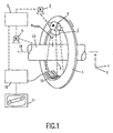
- the computer tomograph shown in Fig. 1 comprises a gantry 1, which is parallel to a can rotate to the z-direction axis of rotation 14. This is the gantry of a motor 2 with a preferably constant, but adjustable Angular velocity driven.
- a radiation source S for example an x-ray tube attached.
- a collimator 3 consisting of the radiation generated by the radiation source S a conical beam 4 hides, i. a beam that is both in the direction of the z-axis and in a to the vertical direction (i.e., in the x-y plane of the one shown in FIG Coordinate system) has a non-zero, finite extent.
- the beam 4 penetrates an unspecified object, which is in a Examination area 13 is located.
- the examination area 13 has the form of a Cylinder, which is also referred to below as an object cylinder.
- the object cylinder 13 strikes the X-ray beam 4 to a on the Gantry 1 attached two-dimensional detector unit 16, which has a number of Detector lines each having a plurality of detector elements. each Detector element detects in each radiation source position a beam from the Beam 4.
- the detector unit 16 may be on a circular arc around the Rotation axis 14 may be arranged, but other detector geometries are possible, e.g. the arrangement on a circular arc around the radiation source S.
- the opening angle of the radiation beam 4 denoted by ⁇ max (the opening angle is defined as the angle which a ray of the bundle 4 bordering in the xy plane encloses with a plane defined by the radiation source S and the axis of rotation 14) determines the diameter of the beam Object cylinder 13, within which the object to be examined must be in the acquisition of the measured values.
- the examination area 13 - or an object located therein, for example a patient located on a patient table - can be displaced parallel to the direction of the rotation axis 14 or the z axis by means of a motor 5.
- The, speed of this feed in the z-direction is constant and preferably adjustable.
- the measurement data acquired by the detector unit 16 become a Image processing computer 10 supplied, from which the absorption distribution in the of Reconstructed beam cone 4 detected part of the examination area 13 and, for. on a monitor 11 reproduces.
- the two engines 2 and 5, the Image processing computer 10, the radiation source S and the transfer of the measurement data from the Detector unit 16 to the image processing computer 10 are of a suitable Control unit 7 controlled.
- the Control unit 7 can also control the motors 2 and 5 so that the ratio of Feed rate v of the examination area 13 and the angular velocity ⁇ of the gantry are in a constant ratio.
- the move Radiation source S and the examination area relative to each other on a helical Train In the following, only this helical scanning movement will be considered. in the Principle it is the case in a helical scanning movement whether the scanning unit S, 16 and the examination area 13 perform the rotational or feed movement; only the relative movement is essential.
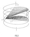
- this Beam bundles in other planes contains fan-shaped grouped rays, should in the following only such Stiahlenkombinationen be referred to as fan beams, the - As the fan beam 400 - lie in a direction parallel to the axis of rotation 14 level.
- the Measurement data of each fan beam can from a parallel to the axis of rotation 14th extending column of detector elements of the detector unit to be detected.
- the opening of the collimator assembly 3 is designed so that two of the radiation source opposite, by the distance 3p staggered (p corresponds the advance in the z-direction during a complete rotation of the radiation source S) windings of the helix 17 coincide with the rays at the upper and lower edge (with reference to the illustration in FIG. 2) of the beam 4.
- the upper and lower edge of the detector window according to the invention coincides with the Projection of the turns of the helix (or their opposite the radiation source Sections) to the detector unit together, i. that from the radiation source outgoing connecting lines with the mentioned edges intersect these Turns.
- the detector window is not on a through the Helix defined arc of a circle located about the axis of rotation, but e.g. on one Arc around the radiation source S, which gives special advantages.
- that has Detector window no longer the shape of a regular parallelogram shown in Fig. 3, but forms a distorted parallelogram whose upper and lower sides are curved are.
- FIG. 3 illustrates the development of the detector window 160 from the cylinder defined by the helix 17 into the plane of the drawing.
- the development takes the form of a parallelogram with sides 161, 162 which are parallel to the z-direction (the larger the distance from one another the opening angle ⁇ max of the beam is).
- h 3p.
- Fig. 3 also the center 165 of the detector window is also drawn, and with the dashed lines 166 and 167, the projection of the two turns is referred to, which lie between the turns of the helix, with the upper edge 163 and the lower edge 164th fall together.
- Each point in the examination area becomes at its entrance into the conical Beam 4 on the lower edge 164 and on its exit from the beam projected onto the upper edge 163. It can be shown that the radiation source around the The point in question performs a rotation of exactly 3 ⁇ , while its projection itself from the lower edge 164 of the detector window has moved to the upper edge 163. Relative to the rotation axis, the one executed by the radiation source Rotational motion but be greater or less than 3 ⁇ .
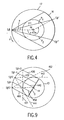
- FIG. 4 illustrates the geometric relationships in a view parallel to the z-axis or to the axis of rotation 14.
- the helix 17 goes into a circle and the axis of rotation 14 into a point, the center of this circle.
- the radiation source moves on the path 17 in the direction of the arrow s, and a beam 411 is shown, which radiates through a point P 1 at the moment when it enters the beam cone.
- the radiation source After the radiation source has rotated from its position ⁇ by one complete revolution and additionally by the angle ⁇ + 2 ⁇ (in total by the angle 3 ⁇ + ⁇ ), it is in a position S ⁇ in which the projection of the upper point P 1 passes just the upper edge 163 of the detector window and which - with respect to the point P 1 - is rotated by exactly 3 ⁇ (relative to the initial position of the radiation source).
- a point P 2 is shown, at its entry into the beam, the radiation source is also in the position S ⁇ , but when they exit it, the position S ⁇ . occupies.
- the radiation source has rotated by exactly 3 ⁇ around the point P 2, but only by the angle 3 ⁇ -2 ⁇ around the axis of rotation.
- the point P 1 is therefore proportional to the rotation angle (3 ⁇ + 2 ⁇ ) longer than the point P 2 (with the rotation angle 3 ⁇ -2 ⁇ ) in the kegekförmigen beam.
- FIG. 5 shows a detector unit whose Settlement corresponds to a rectangle and whose dimensions in the z-direction so chosen are that they include at least the detector window 160. There then remain the in 5 hatched areas 168, 169 at the upper and lower detector edge, which taper to the left or to the right.
- the rectangle shown in FIG. 5 is larger than for the reception of the detector window 160 required; i.e. a part of its detector elements is not exploited.
- This Unused portion can be reduced if the detector unit from a first Position (for a circular scanning movement), in which its axis of symmetry parallel to Rotational axis 14 runs, in a second position (for a helical scanning movement) is tilted, in which its axis of symmetry with the axis of rotation 14 an acute angle forms.
- the upper and lower edges 168, 169 are then so with respect to the axis of rotation inclined like the turns of the helix.
- FIG. 6 shows the development of the detector window 160 '(or the Detector unit 16) used in the aforementioned known CT apparatus, at the same, rectangular detector unit 16 as in Fig. 5. It can be seen that the Slope of the top and bottom of the resulting detector window 160 'one order have a factor of about 3 greater slope than in Fig. 5 and Fig. 3. In addition it can be seen that the stripes 168 'and 169' necessary for the rectangle, which are the Contain detector elements whose measured values are not required during the reconstruction are wider than the strips 168, 169 in Fig. 5. The invention uses the Detector surface so better.
- Fig. 7 shows an advantageous embodiment of the detector unit 16.
- the detector element D 01 is located in the middle row and in the middle column.
- its center 165 'does not coincide with the center 165 of the detector window, which is defined by the piercing point of a straight line originating from the radiation source S and perpendicularly intersecting the axis of rotation 14. Rather, there is an offset between these points, which is in the column direction (or in the direction of the axis of rotation 14) and in the line direction d / 4, where d corresponds to the width or length of a detector element.
- measurement data is acquired in block 101, wherein the User can specify whether during a feed in the z-direction according to the Height h of the detector window, the radiation source by the angle 3 ⁇ (5 ⁇ , 7 ⁇ ...) or to to rotate the angle ⁇ .
- This choice has - as explained above - on the Data acquisition and the quality of the reconstruction, although a significant influence, however, the actual reconstruction process need only be slightly modified. Reference is therefore made to the description of the reconstruction method in FIG WO 98/30980.
- a rebinning first takes place in which, in a first step, Groups of fan beams lying in parallel planes are formed.
- Fan compartments - such as the compartments 400 in Fig. 2 - composed think that in the Rotationsache 14 parallel planes lie.
- these go Layers or fan beams in straight lines.
- Fig. 9 shows a single group of such fan beams, wherein the plane of the drawing perpendicular to the axis of rotation 14 - as well as in Fig. 4.
- successive positions of the radiation source are denoted by S ⁇ -2 ... S ⁇ 0 ... S ⁇ 2 . From each of these radiation source positions, a fan beam 420... 440...
- the 460 passes through the examination region 13 and lies in a plane which is parallel to the plane defined by the mean detector position S ⁇ 0 and the axis of rotation 14 ,
- the sum of the fan angle a that is the angle enclosed by the plane of the fan beam with the plane defined by the associated beam source position and the axis of rotation 14
- the angle the beam source makes with the axis of rotation 14 is constant. If, in a radiation source position, no fan beam exactly fulfills this condition, a beam fan located in this plane is determined by interpolation from beam compartments lying on both sides of the plane with the sought-after orientation and generated in the relevant beam source position.
- fan beams e.g. 421, 441 and 442, 462, respectively each lie on the edge of a beam cone (and thus the examination area tangent).
- these fan beams do not belong to that shown in FIG. 9 Group and are therefore shown in dashed lines - and not in solid lines like the belonging to the group fan beams.
- FIG. 9 also shows a virtual detector window D belonging to the illustrated group, which is perpendicular to the planes of the fan beams and through the axis of rotation 14.
- the virtual detector window D is rectangular and has the height h / 2 and 1.5p, respectively, with the center of the virtual detector window defined by the perpendicular from the central radiation source position S ⁇ 0 on the axis of rotation.
- the radiation source position S ⁇ -2 and S ⁇ 2 are offset in the z-direction from the central radiation source position S ⁇ 0 in the z-direction, it can be shown that the upper and lower Rasdstrahlen the fan beams 420 and 460 exactly with the upper and lower edge of the virtual detector window D coincide.
- step 102 the (parallel to the rotation axis planes) are Fan beams each assigned to one of the different groups. If one of the Radial source positions at the beginning and at the end of the helical scan path 17 There is one group for each radiation source position. Each group includes one virtual detector D whose plane rectangular surface is perpendicular to the planes, in which the fan beams belonging to this group are located.
- the second part of the rebinning namely the Uminterpolation or resampling.
- the distance of the parallel takes Layers, in which there are the street fans located to a group, from the Center outwards. Therefore, in step 103, for a regular Cartesian Grid on the virtual detector window D the associated measurement data from the in step Determined 102 the individual groups of measured data, preferably by Interpolation.
- This is a rebinning of a parallel fan geometry to a rectangular area with regularly distributed grid points is what the following Processing much easier.
- step 104 a one-dimensional filtering.
- Steps 102 and 103 for rebinning are just a simple one one-dimensional location-independent filter is required, which the measurement data in the virtual Detector window D in the line direction, i. perpendicular to the axis of rotation 14, filters.
- This Filter has a linear decreasing attenuation with frequency.
- the filtering can be done in Principle effected by the fact that resulting from the rebinning measurement data of a Convolution with a suitable one-dimensional filter kernel become.
- step 104 first provides a Fourier transformation, according to which in this way in the spatial frequency space transposed data subjected to a ramped filtering in the row direction are then returned to the spatial domain by an inverse Fourier transform to be transformed back.
- step 105 the filtered data of each group or each of the virtual detector window re-projected back into the examination area, i. the Filtered data are groupwise and along the same (by the step 103 possibly slightly modified) radiation paths into the examination area backprojected, along which they were acquired.
- the Absoptions uncomfortable for the individually Voxels of the examination area result from the superimposition of all (filtered) measurement data, upon acquisition of the relevant voxel on the detector window 160 was projected.
- the absorption distribution in the examination area can be determined from the with the Detector according to the invention acquired measured data reconstructed in other ways become.
- a suitable other reconstruction method is from Phys. Med. Biol. 43 (1998) 1015-1024.
Landscapes
- Health & Medical Sciences (AREA)
- Life Sciences & Earth Sciences (AREA)
- Engineering & Computer Science (AREA)
- Medical Informatics (AREA)
- Nuclear Medicine, Radiotherapy & Molecular Imaging (AREA)
- General Health & Medical Sciences (AREA)
- Physics & Mathematics (AREA)
- Radiology & Medical Imaging (AREA)
- Pathology (AREA)
- Heart & Thoracic Surgery (AREA)
- Pulmonology (AREA)
- High Energy & Nuclear Physics (AREA)
- Biophysics (AREA)
- Biomedical Technology (AREA)
- Theoretical Computer Science (AREA)
- Molecular Biology (AREA)
- Surgery (AREA)
- Animal Behavior & Ethology (AREA)
- Optics & Photonics (AREA)
- Public Health (AREA)
- Veterinary Medicine (AREA)
- Chemical & Material Sciences (AREA)
- Analytical Chemistry (AREA)
- Biochemistry (AREA)
- General Physics & Mathematics (AREA)
- Immunology (AREA)
- Apparatus For Radiation Diagnosis (AREA)
- Analysing Materials By The Use Of Radiation (AREA)
Description
- einer Abtasteinheit, die eine Strahlenquelle und eine damit verbundene Detektoreinheit zur Erfassung eines von der Strahlenquelle emittierten, kegelförmigen Strahlenbündels nach dem Durchgang durch einen Untersuchungsbereich bzw. durch ein darin befindliches Objekt umfaßt,
- einer Antriebsanordnung zur Erzeugung einer eine Rotation um eine Rotationsachse (14) und einen Vorschub in Richtung parallel zur Rotationsachse umfassenden Relativbewegung zwischen der Abtasteinheit und dem Untersuchungsbereich bzw. dem Objekt in Form einer Helix (17)
- und mit einer Rekonstruktionseinheit zur Rekonstruktion der räumlichen Verleitung der Absorption innerhalb des Untersuchungsbereiches aus den von der Detektoreinheit innerhalb eines durch die Helix definierten Detektorfensters akquirierten Meßdaten.
In diesem Fall gibt es keine Information, weil die zu rekonstruierende Ebene das Objekt nicht schneidet.
In diesem Fall werden bei dem bekannten Verfahren ebenso wie bei der Erfindung die gleichen Meßdaten akquiriert.
In diesem Fall wird die Rekonstruktion wie bei dem bekannten Verfahren durchgeführt und das Ergebnis wird durch 3 dividiert (wenn die Dptektorabmessung h dem Dreifachen des Abstandes der Detektorwindungen entspricht).
Claims (6)
- Computertomograph mitdadurch gekennzeichnet, daß die Verbindungsgeraden der Strahlenquelle (S) mit den beiden in Richtung der Rotationsachse (14) gegeneinander versetzten Rändern (163, 164) des Detektorfensters (160) zwei in Richtung der Rotationsachse um die Strecke (2n+1)p versetzte Abschnitte der Helix (17) schneiden, wobei n eine ganze Zahl ≥ 1 ist und p dem achsialen Versatz zweier benachbarter Windungen der Helix entspricht.einer Abtasteinheit, die eine Strahlenquelle (S) und eine damit verbundene Detektoreinheit (16) zur Erfassung eines von der Strahlenquelle emittierten, kegelförmigen Strahlenbündels nach dem Durchgang durch einen Untersuchungsbereich (13) bzw. durch ein darin befindliches Objekt umfaßt,einer Antriebsanordnung (2,5) zur Erzeugung einer eine Rotation um eine Rotationsachse (14) und einen Vorschub in Richtung parallel zur Rotationsachse umfassenden Relativbewegung in Form einer Helix (17) zwischen der Abtasteinheit (S,16) und dem Untersuchungsbereich (13) bzw. dem Objektund mit einer Rekonstruktionseinheit (10) zur Rekonstruktion der räumlichen Verteilung der Absorption innerhalb des Untersuchungsbereiches (13) aus den von der Detektoreinheit (16) innerhalb eines durch die Helix (17) definierten Detektorfensters (160) akquirierten Meßdaten
- Computertomograph nach Anspruch 1,
dadurch gekennzeichnet, daß n=1 ist. - Computertomograph nach Anspruch 1, wobei die Detektoreinheit (16) in Zeilen und Spalten angeordnete Detektorelemente (D01 , D02 ...) umfaßt,
dadurch gekennzeichnet, daß die Mitte der Zeilen gegenüber einer die Strahlenquelle und die Rotationsachse enthaltenden Ebene um ein Viertel der Breite (d) eines Detektorelements versetzt ist. - Computertomograph nach Anspruch 1, wobei die Detektoreinheit in Zeilen und Spalten angeordnete Detektorelemente umfaßt,
dadurch gekennzeichnet, daß die Mitte der Spalten gegenüber einer die Strahlenquelle enthaltenden und zur Rotationsachse senkrechten Ebene die Hälfte der Breite eines Detektorelements versetzt ist. - Computenomograph nach Anspruch 1,
dadurch gekennzeichnet, daß die Antriebsanordnung (2, 5) zwei Betriebsmodi aufweist wobei in dem einen Betriebsmodus das Verhältnis zwischen der Rotationsgeschwindigkeit und der Vorschub-Geschwindigkeit um einen Faktor 2n+1 kleiner ist als im anderen Betriebsmodus, sodaß im einen,Betriebsmodus jeder Punkt (P1)im Untersuchungsbereich (13) von der Strahlenquelle (S) aus einem Winkelbereich von π und im anderen Betriebsmodus aus einem Winkelbereich von (2n+1)π von der Strahlenquelle bestrahlt wird. - Computertomograph nach Anspruch 1,
gekennzeichnet durch,a) Mittel zum Rebinning der Meßdaten zu einer Anzahl von Gruppen, wobei jede Gruppe mehrere zur Rotationsachse parallele Ebenen umfaßt, in denen sich je ein Strahlenfächer befindet,b) Mittel zur Filterung der durch das Rebinning erzeugten Daten einer jeden Gruppe in Richtung senkrecht zur Rotationsachse,c) Rekonstruktion der räumlichen Verteilung der Absorption durch die Rückprojektion der gefilterten Daten von mehreren Gruppen.
Applications Claiming Priority (2)
| Application Number | Priority Date | Filing Date | Title |
|---|---|---|---|
| DE19835296 | 1998-08-05 | ||
| DE19835296A DE19835296A1 (de) | 1998-08-05 | 1998-08-05 | Computertomograph mit kegelförmigen Strahlenbündel und helixförmiger Abtastbahn |
Publications (3)
| Publication Number | Publication Date |
|---|---|
| EP0981995A2 EP0981995A2 (de) | 2000-03-01 |
| EP0981995A3 EP0981995A3 (de) | 2002-08-21 |
| EP0981995B1 true EP0981995B1 (de) | 2005-08-31 |
Family
ID=7876492
Family Applications (1)
| Application Number | Title | Priority Date | Filing Date |
|---|---|---|---|
| EP99202483A Expired - Lifetime EP0981995B1 (de) | 1998-08-05 | 1999-07-28 | Computertomograph mit kegelförmigem Strahlenbündel und helixförmiger Abtastbahn |
Country Status (4)
| Country | Link |
|---|---|
| US (1) | US6269141B1 (de) |
| EP (1) | EP0981995B1 (de) |
| JP (1) | JP2000051198A (de) |
| DE (2) | DE19835296A1 (de) |
Families Citing this family (28)
| Publication number | Priority date | Publication date | Assignee | Title |
|---|---|---|---|---|
| DE19956585A1 (de) * | 1999-11-25 | 2001-05-31 | Philips Corp Intellectual Pty | Computertomographie-Verfahren |
| DE10026566A1 (de) | 2000-05-30 | 2001-12-13 | Siemens Ag | Computertomograph |
| DE10038328A1 (de) * | 2000-08-05 | 2002-02-14 | Philips Corp Intellectual Pty | Computertomograph mit kegelförmigen Strahlenbündel und helixförmiger Relativbewegung |
| DE10059886A1 (de) * | 2000-12-01 | 2002-06-20 | Basf Coatings Ag | Verwendung von wässrigen, physikalisch härtbaren Beschichtungsstoffen auf Polyurethanbasis als Haftgrundierung von Lackierungen |
| DE10121441A1 (de) * | 2001-05-02 | 2002-11-07 | Philips Corp Intellectual Pty | Computertomograph |
| DE10126651A1 (de) | 2001-06-01 | 2002-12-12 | Basf Coatings Ag | Pulverlacksuspensionen (Pulverslurries) und Pulverlacke, Verfahren zu ihrer Herstellung und ihre Verwendung |
| US6459756B1 (en) | 2001-10-30 | 2002-10-01 | Siemens Corporate Research, Inc. | System and method for providing normalization correction for image reconstruction in a reduced pitch spiral scan cone beam computed tomography imaging system |
| DE10162768A1 (de) | 2001-12-20 | 2003-07-03 | Philips Intellectual Property | Computertomograph |
| US6754300B2 (en) * | 2002-06-20 | 2004-06-22 | Ge Medical Systems Global Technology Company, Llc | Methods and apparatus for operating a radiation source |
| US6751283B2 (en) | 2002-08-06 | 2004-06-15 | Koninklijke Philips Electronics, N.V. | Reconstruction method for tilted-gantry computed tomography |
| US6775346B2 (en) * | 2002-10-21 | 2004-08-10 | Koninklijke Philips Electronics N.V. | Conebeam computed tomography imaging |
| US7945021B2 (en) | 2002-12-18 | 2011-05-17 | Varian Medical Systems, Inc. | Multi-mode cone beam CT radiotherapy simulator and treatment machine with a flat panel imager |
| JP4553894B2 (ja) * | 2003-02-14 | 2010-09-29 | コーニンクレッカ フィリップス エレクトロニクス エヌ ヴィ | 正確な再構成を伴うヘリカルコーンビームコンピュータトモグラフィのためのシステム及び方法 |
| DE10353638A1 (de) | 2003-11-17 | 2005-06-23 | Basf Coatings Ag | Strukturviskose, wässrige Dispersionen, Verfahren zu ihrer Herstellung und ihre Verwendung |
| US7570730B2 (en) * | 2004-03-17 | 2009-08-04 | Koninklijke Philips Electronics N.V. | Multiple focus acquisition |
| CN1946342A (zh) * | 2004-04-21 | 2007-04-11 | 皇家飞利浦电子股份有限公司 | 锥束相干散射计算机断层摄影装置 |
| US7583777B2 (en) * | 2004-07-21 | 2009-09-01 | General Electric Company | Method and apparatus for 3D reconstruction of images |
| US9498167B2 (en) | 2005-04-29 | 2016-11-22 | Varian Medical Systems, Inc. | System and methods for treating patients using radiation |
| US7778387B2 (en) * | 2005-05-13 | 2010-08-17 | Koninklijke Philips Electronics N. V. | Reconstruction method for helical cone-beam CT |
| JP4717511B2 (ja) * | 2005-05-20 | 2011-07-06 | ジーイー・メディカル・システムズ・グローバル・テクノロジー・カンパニー・エルエルシー | X線ct画像再構成方法およびx線ct装置 |
| US7880154B2 (en) | 2005-07-25 | 2011-02-01 | Karl Otto | Methods and apparatus for the planning and delivery of radiation treatments |
| JP4509903B2 (ja) * | 2005-09-27 | 2010-07-21 | ジーイー・メディカル・システムズ・グローバル・テクノロジー・カンパニー・エルエルシー | X線ct装置 |
| EP2088925B8 (de) | 2006-11-17 | 2015-06-17 | Varian Medical Systems, Inc. | Dynamisches patientenpositionierungssystem |
| USRE46953E1 (en) | 2007-04-20 | 2018-07-17 | University Of Maryland, Baltimore | Single-arc dose painting for precision radiation therapy |
| JP5537132B2 (ja) * | 2008-12-11 | 2014-07-02 | 株式会社東芝 | X線コンピュータ断層撮影装置、医用画像処理装置、及び医用画像処理プログラム |
| EP2585854B1 (de) | 2010-06-22 | 2020-03-18 | Varian Medical Systems International AG | System und verfahren zur messung und zur änderung einer gemessenen strahlendosis |
| US10806409B2 (en) | 2016-09-23 | 2020-10-20 | Varian Medical Systems International Ag | Medical systems with patient supports |
| CN115598719B (zh) * | 2021-07-07 | 2024-06-07 | 同方威视技术股份有限公司 | 检查系统和方法 |
Family Cites Families (9)
| Publication number | Priority date | Publication date | Assignee | Title |
|---|---|---|---|---|
| JPS62139630A (ja) * | 1985-12-16 | 1987-06-23 | 株式会社日立メディコ | X線ct装置 |
| US5485493A (en) * | 1988-10-20 | 1996-01-16 | Picker International, Inc. | Multiple detector ring spiral scanner with relatively adjustable helical paths |
| US5335255A (en) * | 1992-03-24 | 1994-08-02 | Seppi Edward J | X-ray scanner with a source emitting plurality of fan beams |
| US5291402A (en) * | 1992-08-07 | 1994-03-01 | General Electric Company | Helical scanning computed tomography apparatus |
| DE4321080C1 (de) * | 1993-06-24 | 1994-12-08 | Siemens Ag | Computertomograph mit Spiralabtastung |
| JPH0910203A (ja) * | 1995-06-26 | 1997-01-14 | Ge Yokogawa Medical Syst Ltd | X線断層撮影方法及びx線断層撮影装置 |
| CN1107290C (zh) * | 1996-05-02 | 2003-04-30 | 西门子公司 | 计算机层析x射线摄影机的图像再现方法 |
| WO1998030980A1 (en) * | 1997-01-14 | 1998-07-16 | Edholm, Paul | Technique and arrangement for tomographic imaging |
| US5963614A (en) * | 1997-11-26 | 1999-10-05 | General Electric Company | Filters for single slice helical image reconstruction in a computed tomography system |
-
1998
- 1998-08-05 DE DE19835296A patent/DE19835296A1/de not_active Withdrawn
-
1999
- 1999-07-28 EP EP99202483A patent/EP0981995B1/de not_active Expired - Lifetime
- 1999-07-28 DE DE59912486T patent/DE59912486D1/de not_active Expired - Lifetime
- 1999-08-03 JP JP11220209A patent/JP2000051198A/ja not_active Ceased
- 1999-08-05 US US09/368,850 patent/US6269141B1/en not_active Expired - Fee Related
Also Published As
| Publication number | Publication date |
|---|---|
| EP0981995A2 (de) | 2000-03-01 |
| JP2000051198A (ja) | 2000-02-22 |
| US6269141B1 (en) | 2001-07-31 |
| EP0981995A3 (de) | 2002-08-21 |
| DE19835296A1 (de) | 2000-02-10 |
| DE59912486D1 (de) | 2005-10-06 |
Similar Documents
| Publication | Publication Date | Title |
|---|---|---|
| EP0981995B1 (de) | Computertomograph mit kegelförmigem Strahlenbündel und helixförmiger Abtastbahn | |
| EP0989520B1 (de) | Computertomographie-Verfahren mit kegelförmigem Strahlenbündel | |
| EP0990892B1 (de) | Computertomographie-Verfahren mit kegelförmigen Strahlenbündel, und Computertomograph | |
| DE60027930T2 (de) | Ct-scanner mit zeitkohärenter grossflächiger abdeckung | |
| DE69115248T2 (de) | Rechnergesteuerte dreidimensionale tomographische abtastung zur gewinnung von daten von objekten, deren abmessung grösser ist als der strahlungskegel. | |
| EP1150251B1 (de) | Computertomographie-Verfahren | |
| DE19525605B4 (de) | Röntgen-Detektoranordnung mit verringertem effektivem Abstand | |
| DE19929646A1 (de) | Verfahren und Vorrichtung zur Bildrekonstruktion in einem mit Kegelstrahl arbeitenden Bildgabesystem | |
| DE102007039573A1 (de) | Verfahren zur analytischen Rekonstruktion für eine Mehrfachquellen-Inversgeometrie-CT | |
| EP1116475B1 (de) | Computertomographie-Verfahren zur Erzeugung eines Scannogramms | |
| DE19856026A1 (de) | Verfahren und Vorrichtung zur dreidimensionalen Abbildung mit computerisierter Tomographie | |
| EP1310785B1 (de) | Fluoroskopisches Computertomographie-Verfahren, Computertomograph und Computerprogramm zur Verarbeitung der Messwerte eines Computertomographen | |
| DE69229979T2 (de) | Verfahren und Gerät zum Erfassen von vollständigen Radondaten zur exakten Erstellung eines dreidimensionalen CT-Bildes eines Teiles von einem mit Strahlung eines konischen Quelle belegten Objekt | |
| DE10159927B4 (de) | Verfahren zur Bildrekonstruktion für die Computertomographie | |
| EP1177767B1 (de) | Computertomograph mit kegelförmigem Strahlenbündel und helixförmiger Relativbewegung | |
| DE102007021023A1 (de) | Verfahren zur Bilderstellung für die Spiral-CT mit veränderlichem Pitch und CT-Gerät zur Durchführung des Verfahrens | |
| EP1321100A2 (de) | Computertomograph | |
| DE10204926A1 (de) | Sequentielles Computertomographie-Verfahren | |
| DE69732560T2 (de) | Vorrichtung und Verfahren zur Kegelstrahlherstellung | |
| DE60306417T2 (de) | Verfahren und vorrichtung zur exakten kegelstrahlcomputertomographie | |
| EP1085467B1 (de) | Computertomographie-Verfahren mit helixförmiger Relativbewegung | |
| EP1000408B1 (de) | Computertomographie-verfahren mit helixförmiger abtastung eines untersuchungsbereichs | |
| EP1213685B1 (de) | Computertomographie-Verfahren mit helixförmiger Relativbewegung | |
| DE19956585A1 (de) | Computertomographie-Verfahren | |
| DE10215890A1 (de) | Computertomographieverfahren mit kegelförmigen Strahlenbündeln |
Legal Events
| Date | Code | Title | Description |
|---|---|---|---|
| PUAI | Public reference made under article 153(3) epc to a published international application that has entered the european phase |
Free format text: ORIGINAL CODE: 0009012 |
|
| AK | Designated contracting states |
Kind code of ref document: A2 Designated state(s): AT BE CH CY DE DK ES FI FR GB GR IE IT LI LU MC NL PT SE |
|
| AX | Request for extension of the european patent |
Free format text: AL;LT;LV;MK;RO;SI |
|
| RTI1 | Title (correction) |
Free format text: COMPUTER TOMOGRAPH WITH CONICAL BEAM AND HELICAL SOURCE TRAJECTORY |
|
| PUAL | Search report despatched |
Free format text: ORIGINAL CODE: 0009013 |
|
| AK | Designated contracting states |
Kind code of ref document: A3 Designated state(s): AT BE CH CY DE DK ES FI FR GB GR IE IT LI LU MC NL PT SE |
|
| AX | Request for extension of the european patent |
Free format text: AL;LT;LV;MK;RO;SI |
|
| RIC1 | Information provided on ipc code assigned before grant |
Free format text: 7A 61B 6/03 A, 7G 01N 23/04 B |
|
| RAP1 | Party data changed (applicant data changed or rights of an application transferred) |
Owner name: KONINKLIJKE PHILIPS ELECTRONICS N.V. Owner name: PHILIPS CORPORATE INTELLECTUAL PROPERTY GMBH |
|
| 17P | Request for examination filed |
Effective date: 20030221 |
|
| AKX | Designation fees paid |
Designated state(s): DE FR GB NL |
|
| RAP1 | Party data changed (applicant data changed or rights of an application transferred) |
Owner name: KONINKLIJKE PHILIPS ELECTRONICS N.V. Owner name: PHILIPS INTELLECTUAL PROPERTY & STANDARDS GMBH |
|
| GRAP | Despatch of communication of intention to grant a patent |
Free format text: ORIGINAL CODE: EPIDOSNIGR1 |
|
| GRAS | Grant fee paid |
Free format text: ORIGINAL CODE: EPIDOSNIGR3 |
|
| GRAA | (expected) grant |
Free format text: ORIGINAL CODE: 0009210 |
|
| AK | Designated contracting states |
Kind code of ref document: B1 Designated state(s): DE FR GB NL |
|
| PG25 | Lapsed in a contracting state [announced via postgrant information from national office to epo] |
Ref country code: NL Free format text: LAPSE BECAUSE OF FAILURE TO SUBMIT A TRANSLATION OF THE DESCRIPTION OR TO PAY THE FEE WITHIN THE PRESCRIBED TIME-LIMIT Effective date: 20050831 Ref country code: GB Free format text: LAPSE BECAUSE OF FAILURE TO SUBMIT A TRANSLATION OF THE DESCRIPTION OR TO PAY THE FEE WITHIN THE PRESCRIBED TIME-LIMIT Effective date: 20050831 |
|
| REG | Reference to a national code |
Ref country code: GB Ref legal event code: FG4D Free format text: NOT ENGLISH |
|
| REF | Corresponds to: |
Ref document number: 59912486 Country of ref document: DE Date of ref document: 20051006 Kind code of ref document: P |
|
| NLV1 | Nl: lapsed or annulled due to failure to fulfill the requirements of art. 29p and 29m of the patents act | ||
| GBV | Gb: ep patent (uk) treated as always having been void in accordance with gb section 77(7)/1977 [no translation filed] |
Effective date: 20050831 |
|
| ET | Fr: translation filed | ||
| PLBE | No opposition filed within time limit |
Free format text: ORIGINAL CODE: 0009261 |
|
| STAA | Information on the status of an ep patent application or granted ep patent |
Free format text: STATUS: NO OPPOSITION FILED WITHIN TIME LIMIT |
|
| 26N | No opposition filed |
Effective date: 20060601 |
|
| PGFP | Annual fee paid to national office [announced via postgrant information from national office to epo] |
Ref country code: FR Payment date: 20100812 Year of fee payment: 12 |
|
| PGFP | Annual fee paid to national office [announced via postgrant information from national office to epo] |
Ref country code: DE Payment date: 20100930 Year of fee payment: 12 |
|
| REG | Reference to a national code |
Ref country code: FR Ref legal event code: ST Effective date: 20120330 |
|
| PG25 | Lapsed in a contracting state [announced via postgrant information from national office to epo] |
Ref country code: DE Free format text: LAPSE BECAUSE OF NON-PAYMENT OF DUE FEES Effective date: 20120201 Ref country code: FR Free format text: LAPSE BECAUSE OF NON-PAYMENT OF DUE FEES Effective date: 20110801 |
|
| REG | Reference to a national code |
Ref country code: DE Ref legal event code: R119 Ref document number: 59912486 Country of ref document: DE Effective date: 20120201 |