EP0980934A2 - Dispositif pour la dimunition du bruit prés des routes - Google Patents
Dispositif pour la dimunition du bruit prés des routes Download PDFInfo
- Publication number
- EP0980934A2 EP0980934A2 EP19990115370 EP99115370A EP0980934A2 EP 0980934 A2 EP0980934 A2 EP 0980934A2 EP 19990115370 EP19990115370 EP 19990115370 EP 99115370 A EP99115370 A EP 99115370A EP 0980934 A2 EP0980934 A2 EP 0980934A2
- Authority
- EP
- European Patent Office
- Prior art keywords
- soundproofing elements
- soundproofing
- elements
- swung out
- plastic
- Prior art date
- Legal status (The legal status is an assumption and is not a legal conclusion. Google has not performed a legal analysis and makes no representation as to the accuracy of the status listed.)
- Withdrawn
Links
- 230000002787 reinforcement Effects 0.000 claims abstract description 11
- 239000000463 material Substances 0.000 claims abstract description 9
- 239000004033 plastic Substances 0.000 claims abstract description 8
- 229920003023 plastic Polymers 0.000 claims abstract description 8
- 239000002184 metal Substances 0.000 claims abstract description 6
- 239000005060 rubber Substances 0.000 claims abstract description 6
- 239000000203 mixture Substances 0.000 claims abstract 2
- 238000013016 damping Methods 0.000 claims description 6
- 239000000126 substance Substances 0.000 claims description 3
- 230000009969 flowable effect Effects 0.000 claims description 2
- 239000008187 granular material Substances 0.000 claims description 2
- 238000004064 recycling Methods 0.000 claims description 2
- 239000007787 solid Substances 0.000 claims description 2
- 239000002023 wood Substances 0.000 claims description 2
- 239000004744 fabric Substances 0.000 claims 2
- 238000010521 absorption reaction Methods 0.000 abstract description 5
- 238000010276 construction Methods 0.000 abstract description 4
- 238000004519 manufacturing process Methods 0.000 abstract 1
- 238000009413 insulation Methods 0.000 description 11
- 230000004888 barrier function Effects 0.000 description 5
- 238000005452 bending Methods 0.000 description 4
- 230000030279 gene silencing Effects 0.000 description 2
- 239000002985 plastic film Substances 0.000 description 2
- 229920006255 plastic film Polymers 0.000 description 2
- 230000011514 reflex Effects 0.000 description 2
- 229910000831 Steel Inorganic materials 0.000 description 1
- ATJFFYVFTNAWJD-UHFFFAOYSA-N Tin Chemical compound [Sn] ATJFFYVFTNAWJD-UHFFFAOYSA-N 0.000 description 1
- 238000004026 adhesive bonding Methods 0.000 description 1
- 239000003795 chemical substances by application Substances 0.000 description 1
- 238000011161 development Methods 0.000 description 1
- 230000018109 developmental process Effects 0.000 description 1
- 239000013013 elastic material Substances 0.000 description 1
- 238000005516 engineering process Methods 0.000 description 1
- 230000002349 favourable effect Effects 0.000 description 1
- 238000009499 grossing Methods 0.000 description 1
- 238000009434 installation Methods 0.000 description 1
- 239000012774 insulation material Substances 0.000 description 1
- 239000011490 mineral wool Substances 0.000 description 1
- 239000005445 natural material Substances 0.000 description 1
- 230000035515 penetration Effects 0.000 description 1
- 230000001681 protective effect Effects 0.000 description 1
- 239000010959 steel Substances 0.000 description 1
Images


Classifications
-
- E—FIXED CONSTRUCTIONS
- E01—CONSTRUCTION OF ROADS, RAILWAYS, OR BRIDGES
- E01F—ADDITIONAL WORK, SUCH AS EQUIPPING ROADS OR THE CONSTRUCTION OF PLATFORMS, HELICOPTER LANDING STAGES, SIGNS, SNOW FENCES, OR THE LIKE
- E01F8/00—Arrangements for absorbing or reflecting air-transmitted noise from road or railway traffic
- E01F8/0005—Arrangements for absorbing or reflecting air-transmitted noise from road or railway traffic used in a wall type arrangement
- E01F8/0017—Plate-like elements
-
- E—FIXED CONSTRUCTIONS
- E01—CONSTRUCTION OF ROADS, RAILWAYS, OR BRIDGES
- E01F—ADDITIONAL WORK, SUCH AS EQUIPPING ROADS OR THE CONSTRUCTION OF PLATFORMS, HELICOPTER LANDING STAGES, SIGNS, SNOW FENCES, OR THE LIKE
- E01F8/00—Arrangements for absorbing or reflecting air-transmitted noise from road or railway traffic
- E01F8/0005—Arrangements for absorbing or reflecting air-transmitted noise from road or railway traffic used in a wall type arrangement
- E01F8/0029—Arrangements for absorbing or reflecting air-transmitted noise from road or railway traffic used in a wall type arrangement with porous surfaces, e.g. concrete with porous fillers
-
- E—FIXED CONSTRUCTIONS
- E01—CONSTRUCTION OF ROADS, RAILWAYS, OR BRIDGES
- E01F—ADDITIONAL WORK, SUCH AS EQUIPPING ROADS OR THE CONSTRUCTION OF PLATFORMS, HELICOPTER LANDING STAGES, SIGNS, SNOW FENCES, OR THE LIKE
- E01F8/00—Arrangements for absorbing or reflecting air-transmitted noise from road or railway traffic
- E01F8/0005—Arrangements for absorbing or reflecting air-transmitted noise from road or railway traffic used in a wall type arrangement
- E01F8/0088—Suspended, e.g. ropes or mesh
Definitions
- the invention relates to a device for reducing the sound level Traffic routes according to the preamble of claim 1.
- DE 37 38 020 A1 discloses that the wall surfaces the sound insulation walls with round and / or polygonal openings to allow a view through the wall surfaces. This Measures do produce somewhat less noise insulation than full-area ones Soundproof walls.
- the lower noise insulation can be according to DE 37 38 020 A1 however, can be improved by making the openings sloping, inclined Reflex zones are arranged, which partially contain the incoming sound reflect yourself and consequently swallow. According to this document have full-area Noise barriers, on the other hand, have the disadvantage that noise pollution from one side of the street to the driver, for example becomes.
- DE 196 26 676 A1 is a device for reducing sound levels disclosed in buildings in which the soundproofing elements made of plastic micro-perforated and spaced apart are. Such damping elements are then spaced apart from one another and parallel stretched plastic films with a microperforation educated. These sound absorbing elements are preferably attached hanging in an apron-like arrangement within a building or in front massive or translucent surfaces. With this silencing element can be arbitrarily avoided while avoiding mineral wool for sound absorption design figured silencing elements.
- DE 36 34 960 A1 is a noise barrier for traffic routes made of prefabricated Share known which elongated soundproofing elements in hanging Arrangement on top and bottom tensioned wire ropes. This tense Wire ropes are guided over concrete supports and fastened to them.
- substantial elongated soundproofing elements exist A1 from tin boxes or from plastic films, preferably in tubular form manufactured and filled with insulation materials.
- the main advantage of this new type of soundproof wall is the flexible Execution of the wall surfaces seen. Create these flexible walls favorable sound absorption properties and allow a technically simple and for the function optimal installation.
- Crucial to this invention is that the soundproofing elements are flexible and around the upper fastening edge can swing out on both sides. This deliberately becomes a Swung out the soundproofing elements caused by wind load. On such pivoting is by end stops or damping means, as in are limited to the following description of the figures.
- end stops or damping means as in are limited to the following description of the figures.
- the pivoting possibility of the soundproofing elements is achieved that they are a have a sufficiently large mass that is suitable for real sound insulation to offer and record the sound or sound waves on the surfaces and absorb.
- a traffic route for example, a street or a track system. Both Streets can be located both within locations and residential areas Roads as well as fast-moving roads such as highways or federal highways act.
- the sound source 5, which, for example, is located on this traffic route 13 is a moving motor vehicle and basically any sound source or source of noise.
- the arrows 14 represent the towards one Soundproofing element 1 emits sound waves.
- the protective element 1 is located a distance in front of a building 15, of course between the Soundproofing element 1 and the building quiet traffic routes, agricultural Areas, gardens or the like can lie.
- the soundproofing element 1 is facing away from the floor 13 Longitudinal edge 16 is pivotally suspended on a carrying device 2.
- the connection of the soundproofing element 1 on the carrying device 2 allows the soundproofing element 1 a swing out according to the arrows in the two opposite Directions about the longitudinal axis 18.
- Such a pivoting is in mainly caused by wind loads.
- the soundproofing elements are made of a flexible, flexible material are formed, the pivoting of the Soundproofing elements 1 take place approximately after the bending line 19. It means that the free and near-ground end areas are usually bent more than the upper edge of the soundproofing elements 1 in the area of the carrying device 2.
- the sound insulation elements 1 are pivoted out by damping means, for example in the form of tension springs, damped and ultimately also limited.
- damping means 4 are also fixed end stops 3 applicable.
- Soundproofing elements 1 conceivable as a hollow body made of such materials that solid or flowable substances can be filled.
- the soundproofing elements 1 consist of a recycling material.
- the surfaces of the soundproofing elements 1 can be structured or have porous outer skin or also with penetrations or holes be provided. Such surface features are particularly on the Sound source 5 facing surface of the soundproofing elements 1 is provided.
- FIG. 1 shows such structures at 20 or such holes at 21.
- Figure 2 shows a plan view of the device of Figure 1, also here again the essence of the invention is shown only schematically.
- the soundproofing elements 1 run in a line by several such soundproofing elements 1 are arranged side by side.
- the soundproofing elements 1 in an angled shape according to the lower Area in Figure 2 and in a staggered and angled shape according to the upper Area in Figure 2 to be continued side by side.
- With 22 in Figure 2 is on denoting the soundproofing elements 1 attacking wind load.
- the soundproofing elements 1 are, as already explained in FIG. 1, suspended from a carrying device 2, which is in turn held by laterally spaced supports 7. These supports 7 are preferably fixed in the ground by concreting. You can alternatively or additionally, it can also be held by tensioned ropes.
- the swung out lower areas of the soundproofing elements 1 are identified by the reference symbol 23 indicated.
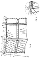
- FIG. 3 A practical embodiment is shown in Figure 3, which the sound insulation elements 1 arranged in an angled manner side by side.
- Columns 7 spaced apart from one another are in the region remote from the ground, i.e. in the area the upper free ends of the supports 7, profiled rails or strips 6 attached, which accommodate the soundproofing elements 1 in a hanging manner.
- This Profile rails or strips can be two strips running parallel to each other be between which the soundproofing elements 1 are clamped by screwing 24 are. Instead of such parallel rails or strips 6 are also other profile bodies, for example U-shaped profiles, round profiles, angle profiles and other shapes possible.
- the strips or rails 6 are on the supports 7 rigidly attached. As a result, the soundproofing elements 1 pivot when they occur Wind load only below the strips 6.
- the strips or rails 6 in this way on the supports 7 are connected so that they can rotate at least to a limited extent about their longitudinal axis.
- Such a bearing arrangement has the advantage that the soundproofing elements 1 can swing out more easily and do not absorb such high bending stress as with a rigid arrangement. Doing so may tear out the soundproofing elements 1 prevented from the strips or rails 6.
- the Soundproofing elements 1 networks 12 stretched which have an at least limited bending, allow the soundproofing elements 1 to bulge and / or swing out, depending on the type of attachment of the nets 12. If the nets according to Figure 3 and 4 both on the upper strips 6 and in the area near the ground are held firmly by pins 25 or other anchors, then when there is a wind load merely bulging or bending the flexible soundproofing elements 1 possible in the middle area.
- the networks 12 can of course be so excited that in the area near the floor, the soundproofing elements can be swung out up to one maximum distance is possible. For this purpose, the networks can be sent to the lower pins or anchors 25 acted upon by spring elements or end stops his.
- FIG. 3 there is a device for preventing this of noise also the possibility of soundproofing elements 1 on top of each other to arrange.
- the lower row of soundproofing elements 1 is in this case a corresponding bar or a profile body 6 attached, the distance runs parallel to the upper rail or bar 6. Even the middle rail or the profile body 6 is connected to the side supports 7.
- Figure 5 shows in a schematically simplified representation again in height stacked soundproofing elements 1, which on an upper and on a middle carrying device 2 are pivotally attached.
- the soundproofing element 1 is provided with a reinforcement 8.
- This Reinforcement in the sense of the invention can be a metal, for example steel, or also be a plastic reinforcement and in the form of a net or as simple continuous strut can be embedded in the soundproofing element 1.
- Such reinforcements 8 are according to Figure 6 on the upper end edge 26 of the soundproofing elements 1 led out. These ends of the reinforcements 8 are used for Attachment to the upper support device 2.
- the soundproofing elements 1 with the support device 2 are to the Soundproofing elements 1 occurring mechanical loads reduced. It will essentially breaking out or crumbling off parts of the soundproofing elements 1 prevented.
- the reinforcements 8 can of course also on the Side edges of the soundproofing elements 1 can be led out, creating a connection of the individual soundproofing elements next to each other or a good attachment the soundproofing elements on the laterally arranged supports 7 is possible. Finally, the reinforcements can also be made from the soundproofing elements on the floor 1 emerge in order to thereby also attach or connect to the bottom guarantee. Such a connection at the bottom would be carried out in this way be that at least a limited pivoting or arching of the soundproofing elements 1 is possible.
- FIG. 7 shows two soundproofing elements 1 which are butted one above the other Gap 27 between the butt-facing end edges of the soundproofing elements 1 is chosen so that the upper soundproofing element with wind load can swing out, with a smoothing over the top facing Front edge of the lower soundproofing element may well be wanted.
- the soundproofing elements arranged one above the other or next to one another can 1 by a shape cut of the mutually directed end edges are at a short distance.
- Figure 8 shows a Z-shaped end section Column 27 left open in this way of joining together or noise protection elements 1 arranged next to one another is pivoted out of the soundproofing element 1 is only possible in one direction, which is shown in FIG arrow 28 is displayed.
- FIG. 9 again shows soundproofing elements 1 which are butted against one another can be provided one above the other or next to each other.
- this case owns the upper soundproofing element 1 in the lower area on both sides of the outer surfaces attached flaps 29.
- flaps are made of a highly elastic material, for example Rubber, trained. But you can also in the form of brushes lower area.
- the attachment is done mechanically by screwing or gluing the tabs 29 to the surfaces of the soundproofing elements 1. Of course it is also conceivable to have such a rag only on one side to install a soundproofing element 1.
- the advantage of this design is that that the gap 27 is covered soundproof.
- the gap 27 can even be carried out relatively large in order to easily swing out the soundproofing elements to enable.
- Attachment of the tabs 29 can also be near the ground Area to be advantageous around the gap between the soundproofing element 1 and to close the ground.
- the soundproofing elements can also simply overlap (height, width) be arranged, for example lamellar or the like.
Landscapes
- Engineering & Computer Science (AREA)
- Architecture (AREA)
- Civil Engineering (AREA)
- Structural Engineering (AREA)
- Devices Affording Protection Of Roads Or Walls For Sound Insulation (AREA)
Applications Claiming Priority (2)
| Application Number | Priority Date | Filing Date | Title |
|---|---|---|---|
| DE19837164 | 1998-08-17 | ||
| DE1998137164 DE19837164A1 (de) | 1998-08-17 | 1998-08-17 | Vorrichtung zur Verminderung des Schallpegels an Verkehrswegen |
Publications (1)
| Publication Number | Publication Date |
|---|---|
| EP0980934A2 true EP0980934A2 (fr) | 2000-02-23 |
Family
ID=7877725
Family Applications (1)
| Application Number | Title | Priority Date | Filing Date |
|---|---|---|---|
| EP19990115370 Withdrawn EP0980934A2 (fr) | 1998-08-17 | 1999-08-04 | Dispositif pour la dimunition du bruit prés des routes |
Country Status (2)
| Country | Link |
|---|---|
| EP (1) | EP0980934A2 (fr) |
| DE (1) | DE19837164A1 (fr) |
Cited By (3)
| Publication number | Priority date | Publication date | Assignee | Title |
|---|---|---|---|---|
| WO2007120061A1 (fr) * | 2006-04-18 | 2007-10-25 | Maciej Grzelski | Procédé de fabrication de panneaux d'isolation phonique et panneau correspondant ainsi fabriqué |
| CN100575610C (zh) * | 2006-12-26 | 2009-12-30 | 李凤娥 | 吸隔声屏障 |
| CN108130865A (zh) * | 2018-02-27 | 2018-06-08 | 山东景中景环保科技有限公司 | 一种阻尼减载声屏障 |
Citations (2)
| Publication number | Priority date | Publication date | Assignee | Title |
|---|---|---|---|---|
| DE3634960A1 (de) | 1986-10-14 | 1988-04-21 | Harry Ing Grad Berghaus | Laermschutzwand fuer verkehrswege |
| DE19626676A1 (de) | 1996-07-03 | 1998-01-08 | Kaefer Isoliertechnik | Vorrichtung zur Verminderung von Schallpegeln in Gebäuden |
-
1998
- 1998-08-17 DE DE1998137164 patent/DE19837164A1/de not_active Withdrawn
-
1999
- 1999-08-04 EP EP19990115370 patent/EP0980934A2/fr not_active Withdrawn
Patent Citations (2)
| Publication number | Priority date | Publication date | Assignee | Title |
|---|---|---|---|---|
| DE3634960A1 (de) | 1986-10-14 | 1988-04-21 | Harry Ing Grad Berghaus | Laermschutzwand fuer verkehrswege |
| DE19626676A1 (de) | 1996-07-03 | 1998-01-08 | Kaefer Isoliertechnik | Vorrichtung zur Verminderung von Schallpegeln in Gebäuden |
Cited By (4)
| Publication number | Priority date | Publication date | Assignee | Title |
|---|---|---|---|---|
| WO2007120061A1 (fr) * | 2006-04-18 | 2007-10-25 | Maciej Grzelski | Procédé de fabrication de panneaux d'isolation phonique et panneau correspondant ainsi fabriqué |
| CN100575610C (zh) * | 2006-12-26 | 2009-12-30 | 李凤娥 | 吸隔声屏障 |
| CN108130865A (zh) * | 2018-02-27 | 2018-06-08 | 山东景中景环保科技有限公司 | 一种阻尼减载声屏障 |
| CN108130865B (zh) * | 2018-02-27 | 2024-06-11 | 山东城市之光市政工程有限公司 | 一种阻尼减载声屏障 |
Also Published As
| Publication number | Publication date |
|---|---|
| DE19837164A1 (de) | 2000-02-24 |
Similar Documents
| Publication | Publication Date | Title |
|---|---|---|
| EP0273911B1 (fr) | Structure anti-bruit portant de la verdure | |
| DE69301857T2 (de) | Leitplanken aus Holz und Metall | |
| EP0014172A1 (fr) | Paroi protectrice servant de dispositif de guidage pour la circulation routière et d'écran anti-bruit pour les riverains | |
| CH684279A5 (de) | Lärmschutzelement für Lärmschutzwände. | |
| CH678870A5 (fr) | ||
| DE1534499A1 (de) | Sicherheitsleitplanke fuer Strassen | |
| DE102007037339B4 (de) | Gabionenwand mit lärmdämmender, monolithischer Schicht aus Beton | |
| AT404147B (de) | Schallschutzwand zur dämmung von schallemissionen von verkehrsmitteln | |
| EP0980934A2 (fr) | Dispositif pour la dimunition du bruit prés des routes | |
| AT409001B (de) | Schallschutzwand | |
| DE202005003255U1 (de) | Lärmschutzwand | |
| DE3009082A1 (de) | Wandelement zum errichten von laermschutzwaenden | |
| CH643313A5 (de) | Abdeckung von landverkehrswegen. | |
| DE19757092C2 (de) | Schutzplankenstrang | |
| DE2616778A1 (de) | Bausatz fuer die herstellung einer laerm- und blendschutzwand | |
| DE2414415A1 (de) | Abschirmung zur schalldaemmung | |
| CH690184A5 (de) | Schallschutzwand zur Dämmung von Schallemissionen. | |
| EP1072726B1 (fr) | Mur antibruit le long d'un chemin | |
| DE19938676A1 (de) | Schallschutzwand für Verkehrswege | |
| DE29823733U1 (de) | Gitterkonstruktion zum Hinterfüllen mit Schüttmaterial | |
| EP1120496A2 (fr) | Ecran insonorisant | |
| AT412734B (de) | Verkehrsfläche | |
| CH616188A5 (en) | Protection wall, in particular for use as a noise-protection wall | |
| DE2432654A1 (de) | Fahrbahn-leitplanke | |
| DE3919280A1 (de) | Schallschutzwand |
Legal Events
| Date | Code | Title | Description |
|---|---|---|---|
| PUAI | Public reference made under article 153(3) epc to a published international application that has entered the european phase |
Free format text: ORIGINAL CODE: 0009012 |
|
| AK | Designated contracting states |
Kind code of ref document: A2 Designated state(s): AT BE CH CY DE DK ES FI FR GB GR IE IT LI LU MC NL PT SE |
|
| AX | Request for extension of the european patent |
Free format text: AL;LT;LV;MK;RO;SI |
|
| STAA | Information on the status of an ep patent application or granted ep patent |
Free format text: STATUS: THE APPLICATION HAS BEEN WITHDRAWN |
|
| 18W | Application withdrawn |
Withdrawal date: 20010808 |