EP0980835B1 - Double chamber aerosol container - Google Patents
Double chamber aerosol container Download PDFInfo
- Publication number
- EP0980835B1 EP0980835B1 EP98124586A EP98124586A EP0980835B1 EP 0980835 B1 EP0980835 B1 EP 0980835B1 EP 98124586 A EP98124586 A EP 98124586A EP 98124586 A EP98124586 A EP 98124586A EP 0980835 B1 EP0980835 B1 EP 0980835B1
- Authority
- EP
- European Patent Office
- Prior art keywords
- inner sack
- top end
- sack
- housing
- weight
- Prior art date
- Legal status (The legal status is an assumption and is not a legal conclusion. Google has not performed a legal analysis and makes no representation as to the accuracy of the status listed.)
- Expired - Lifetime
Links
- 239000000443 aerosol Substances 0.000 title claims description 62
- 238000003780 insertion Methods 0.000 claims description 57
- 230000037431 insertion Effects 0.000 claims description 57
- -1 polypropylene Polymers 0.000 claims description 16
- 229920001684 low density polyethylene Polymers 0.000 claims description 14
- 239000004702 low-density polyethylene Substances 0.000 claims description 14
- 239000000463 material Substances 0.000 claims description 14
- 239000004743 Polypropylene Substances 0.000 claims description 10
- 229920001155 polypropylene Polymers 0.000 claims description 10
- 229920000219 Ethylene vinyl alcohol Polymers 0.000 claims description 8
- 239000004715 ethylene vinyl alcohol Substances 0.000 claims description 8
- RZXDTJIXPSCHCI-UHFFFAOYSA-N hexa-1,5-diene-2,5-diol Chemical compound OC(=C)CCC(O)=C RZXDTJIXPSCHCI-UHFFFAOYSA-N 0.000 claims description 8
- 229910052751 metal Inorganic materials 0.000 claims description 8
- 239000002184 metal Substances 0.000 claims description 8
- 239000004952 Polyamide Substances 0.000 claims description 7
- 229920001903 high density polyethylene Polymers 0.000 claims description 7
- 239000004700 high-density polyethylene Substances 0.000 claims description 7
- 229920002239 polyacrylonitrile Polymers 0.000 claims description 7
- 229920002647 polyamide Polymers 0.000 claims description 7
- 229920000139 polyethylene terephthalate Polymers 0.000 claims description 6
- 239000005020 polyethylene terephthalate Substances 0.000 claims description 6
- 239000002356 single layer Substances 0.000 claims description 4
- 239000004698 Polyethylene Substances 0.000 claims description 3
- 239000013013 elastic material Substances 0.000 claims description 3
- 229920000573 polyethylene Polymers 0.000 claims description 3
- 239000003380 propellant Substances 0.000 description 28
- 239000003795 chemical substances by application Substances 0.000 description 20
- 238000005507 spraying Methods 0.000 description 16
- 239000002917 insecticide Substances 0.000 description 14
- 206010040954 Skin wrinkling Diseases 0.000 description 9
- XLYOFNOQVPJJNP-UHFFFAOYSA-N water Substances O XLYOFNOQVPJJNP-UHFFFAOYSA-N 0.000 description 9
- 230000037303 wrinkles Effects 0.000 description 9
- 238000007789 sealing Methods 0.000 description 7
- 239000002781 deodorant agent Substances 0.000 description 6
- BXWNKGSJHAJOGX-UHFFFAOYSA-N hexadecan-1-ol Chemical compound CCCCCCCCCCCCCCCCO BXWNKGSJHAJOGX-UHFFFAOYSA-N 0.000 description 6
- 230000007774 longterm Effects 0.000 description 6
- 239000000047 product Substances 0.000 description 6
- CWERGRDVMFNCDR-UHFFFAOYSA-N thioglycolic acid Chemical compound OC(=O)CS CWERGRDVMFNCDR-UHFFFAOYSA-N 0.000 description 6
- 238000011282 treatment Methods 0.000 description 6
- 239000007921 spray Substances 0.000 description 5
- 239000004094 surface-active agent Substances 0.000 description 5
- LFQSCWFLJHTTHZ-UHFFFAOYSA-N Ethanol Chemical compound CCO LFQSCWFLJHTTHZ-UHFFFAOYSA-N 0.000 description 4
- 230000008602 contraction Effects 0.000 description 4
- 239000007789 gas Substances 0.000 description 4
- 230000001590 oxidative effect Effects 0.000 description 4
- 239000002304 perfume Substances 0.000 description 4
- 238000004078 waterproofing Methods 0.000 description 4
- DNIAPMSPPWPWGF-UHFFFAOYSA-N Propylene glycol Chemical compound CC(O)CO DNIAPMSPPWPWGF-UHFFFAOYSA-N 0.000 description 3
- HEMHJVSKTPXQMS-UHFFFAOYSA-M Sodium hydroxide Chemical compound [OH-].[Na+] HEMHJVSKTPXQMS-UHFFFAOYSA-M 0.000 description 3
- 230000002378 acidificating effect Effects 0.000 description 3
- 230000001166 anti-perspirative effect Effects 0.000 description 3
- 239000003213 antiperspirant Substances 0.000 description 3
- 229960000541 cetyl alcohol Drugs 0.000 description 3
- KRKNYBCHXYNGOX-UHFFFAOYSA-N citric acid Chemical compound OC(=O)CC(O)(C(O)=O)CC(O)=O KRKNYBCHXYNGOX-UHFFFAOYSA-N 0.000 description 3
- 239000011248 coating agent Substances 0.000 description 3
- 239000002537 cosmetic Substances 0.000 description 3
- 230000002951 depilatory effect Effects 0.000 description 3
- 238000010413 gardening Methods 0.000 description 3
- 239000000118 hair dye Substances 0.000 description 3
- 239000003350 kerosene Substances 0.000 description 3
- 239000001024 permanent hair color Substances 0.000 description 3
- 239000012466 permeate Substances 0.000 description 3
- 230000001131 transforming effect Effects 0.000 description 3
- QGZKDVFQNNGYKY-UHFFFAOYSA-O Ammonium Chemical compound [NH4+] QGZKDVFQNNGYKY-UHFFFAOYSA-O 0.000 description 2
- PEDCQBHIVMGVHV-UHFFFAOYSA-N Glycerine Chemical compound OCC(O)CO PEDCQBHIVMGVHV-UHFFFAOYSA-N 0.000 description 2
- MHAJPDPJQMAIIY-UHFFFAOYSA-N Hydrogen peroxide Chemical compound OO MHAJPDPJQMAIIY-UHFFFAOYSA-N 0.000 description 2
- XUIMIQQOPSSXEZ-UHFFFAOYSA-N Silicon Chemical compound [Si] XUIMIQQOPSSXEZ-UHFFFAOYSA-N 0.000 description 2
- 239000002738 chelating agent Substances 0.000 description 2
- 238000000576 coating method Methods 0.000 description 2
- 239000006071 cream Substances 0.000 description 2
- 230000005574 cross-species transmission Effects 0.000 description 2
- 239000003712 decolorant Substances 0.000 description 2
- 239000003814 drug Substances 0.000 description 2
- 229940079593 drug Drugs 0.000 description 2
- 239000000975 dye Substances 0.000 description 2
- 230000000694 effects Effects 0.000 description 2
- 235000019441 ethanol Nutrition 0.000 description 2
- 239000006260 foam Substances 0.000 description 2
- 239000012770 industrial material Substances 0.000 description 2
- 239000007769 metal material Substances 0.000 description 2
- GLDOVTGHNKAZLK-UHFFFAOYSA-N octadecan-1-ol Chemical compound CCCCCCCCCCCCCCCCCCO GLDOVTGHNKAZLK-UHFFFAOYSA-N 0.000 description 2
- 239000003973 paint Substances 0.000 description 2
- 230000002093 peripheral effect Effects 0.000 description 2
- CPJSUEIXXCENMM-UHFFFAOYSA-N phenacetin Chemical compound CCOC1=CC=C(NC(C)=O)C=C1 CPJSUEIXXCENMM-UHFFFAOYSA-N 0.000 description 2
- 238000009877 rendering Methods 0.000 description 2
- 229920005989 resin Polymers 0.000 description 2
- 239000011347 resin Substances 0.000 description 2
- 238000006748 scratching Methods 0.000 description 2
- 230000002393 scratching effect Effects 0.000 description 2
- 239000002453 shampoo Substances 0.000 description 2
- 229910052710 silicon Inorganic materials 0.000 description 2
- 239000010703 silicon Substances 0.000 description 2
- 238000010257 thawing Methods 0.000 description 2
- WRIDQFICGBMAFQ-UHFFFAOYSA-N (E)-8-Octadecenoic acid Natural products CCCCCCCCCC=CCCCCCCC(O)=O WRIDQFICGBMAFQ-UHFFFAOYSA-N 0.000 description 1
- FFJCNSLCJOQHKM-CLFAGFIQSA-N (z)-1-[(z)-octadec-9-enoxy]octadec-9-ene Chemical compound CCCCCCCC\C=C/CCCCCCCCOCCCCCCCC\C=C/CCCCCCCC FFJCNSLCJOQHKM-CLFAGFIQSA-N 0.000 description 1
- LQJBNNIYVWPHFW-UHFFFAOYSA-N 20:1omega9c fatty acid Natural products CCCCCCCCCCC=CCCCCCCCC(O)=O LQJBNNIYVWPHFW-UHFFFAOYSA-N 0.000 description 1
- QSBYPNXLFMSGKH-UHFFFAOYSA-N 9-Heptadecensaeure Natural products CCCCCCCC=CCCCCCCCC(O)=O QSBYPNXLFMSGKH-UHFFFAOYSA-N 0.000 description 1
- 241000238876 Acari Species 0.000 description 1
- 239000004925 Acrylic resin Substances 0.000 description 1
- 229920000178 Acrylic resin Polymers 0.000 description 1
- VHUUQVKOLVNVRT-UHFFFAOYSA-N Ammonium hydroxide Chemical compound [NH4+].[OH-] VHUUQVKOLVNVRT-UHFFFAOYSA-N 0.000 description 1
- 241001674044 Blattodea Species 0.000 description 1
- OYPRJOBELJOOCE-UHFFFAOYSA-N Calcium Chemical compound [Ca] OYPRJOBELJOOCE-UHFFFAOYSA-N 0.000 description 1
- 102000008186 Collagen Human genes 0.000 description 1
- 108010035532 Collagen Proteins 0.000 description 1
- 206010012504 Dermatophytosis Diseases 0.000 description 1
- KCXVZYZYPLLWCC-UHFFFAOYSA-N EDTA Chemical compound OC(=O)CN(CC(O)=O)CCN(CC(O)=O)CC(O)=O KCXVZYZYPLLWCC-UHFFFAOYSA-N 0.000 description 1
- 241000238631 Hexapoda Species 0.000 description 1
- 229920000663 Hydroxyethyl cellulose Polymers 0.000 description 1
- 239000004354 Hydroxyethyl cellulose Substances 0.000 description 1
- 241001465754 Metazoa Species 0.000 description 1
- 241001460074 Microsporum distortum Species 0.000 description 1
- SECXISVLQFMRJM-UHFFFAOYSA-N N-Methylpyrrolidone Chemical compound CN1CCCC1=O SECXISVLQFMRJM-UHFFFAOYSA-N 0.000 description 1
- 239000005642 Oleic acid Substances 0.000 description 1
- ZQPPMHVWECSIRJ-UHFFFAOYSA-N Oleic acid Natural products CCCCCCCCC=CCCCCCCCC(O)=O ZQPPMHVWECSIRJ-UHFFFAOYSA-N 0.000 description 1
- 229920003171 Poly (ethylene oxide) Polymers 0.000 description 1
- 239000002202 Polyethylene glycol Substances 0.000 description 1
- 229920001214 Polysorbate 60 Polymers 0.000 description 1
- 229920002472 Starch Polymers 0.000 description 1
- VBIIFPGSPJYLRR-UHFFFAOYSA-M Stearyltrimethylammonium chloride Chemical compound [Cl-].CCCCCCCCCCCCCCCCCC[N+](C)(C)C VBIIFPGSPJYLRR-UHFFFAOYSA-M 0.000 description 1
- 208000002474 Tinea Diseases 0.000 description 1
- 239000002253 acid Substances 0.000 description 1
- 230000004913 activation Effects 0.000 description 1
- 239000000853 adhesive Substances 0.000 description 1
- 230000001070 adhesive effect Effects 0.000 description 1
- 150000001412 amines Chemical class 0.000 description 1
- QGZKDVFQNNGYKY-UHFFFAOYSA-N ammonia Natural products N QGZKDVFQNNGYKY-UHFFFAOYSA-N 0.000 description 1
- 230000001741 anti-phlogistic effect Effects 0.000 description 1
- 229940121375 antifungal agent Drugs 0.000 description 1
- 239000003963 antioxidant agent Substances 0.000 description 1
- 230000003078 antioxidant effect Effects 0.000 description 1
- 229910052791 calcium Inorganic materials 0.000 description 1
- 239000011575 calcium Substances 0.000 description 1
- AXCZMVOFGPJBDE-UHFFFAOYSA-L calcium dihydroxide Chemical compound [OH-].[OH-].[Ca+2] AXCZMVOFGPJBDE-UHFFFAOYSA-L 0.000 description 1
- 239000000920 calcium hydroxide Substances 0.000 description 1
- 229910001861 calcium hydroxide Inorganic materials 0.000 description 1
- 230000015556 catabolic process Effects 0.000 description 1
- 125000002091 cationic group Chemical group 0.000 description 1
- 229920002678 cellulose Polymers 0.000 description 1
- 239000001913 cellulose Substances 0.000 description 1
- 229920001436 collagen Polymers 0.000 description 1
- 238000004891 communication Methods 0.000 description 1
- 239000002826 coolant Substances 0.000 description 1
- 229920001577 copolymer Polymers 0.000 description 1
- 239000003599 detergent Substances 0.000 description 1
- 229960001484 edetic acid Drugs 0.000 description 1
- 230000001815 facial effect Effects 0.000 description 1
- 230000002349 favourable effect Effects 0.000 description 1
- 239000000499 gel Substances 0.000 description 1
- 239000011521 glass Substances 0.000 description 1
- 235000011187 glycerol Nutrition 0.000 description 1
- 239000008266 hair spray Substances 0.000 description 1
- 239000004009 herbicide Substances 0.000 description 1
- 230000007062 hydrolysis Effects 0.000 description 1
- 238000006460 hydrolysis reaction Methods 0.000 description 1
- 235000019447 hydroxyethyl cellulose Nutrition 0.000 description 1
- 239000000077 insect repellent Substances 0.000 description 1
- 150000002500 ions Chemical group 0.000 description 1
- QXJSBBXBKPUZAA-UHFFFAOYSA-N isooleic acid Natural products CCCCCCCC=CCCCCCCCCC(O)=O QXJSBBXBKPUZAA-UHFFFAOYSA-N 0.000 description 1
- 239000007788 liquid Substances 0.000 description 1
- 229940057995 liquid paraffin Drugs 0.000 description 1
- 239000006210 lotion Substances 0.000 description 1
- 239000000314 lubricant Substances 0.000 description 1
- 238000000034 method Methods 0.000 description 1
- 230000003387 muscular Effects 0.000 description 1
- GOQYKNQRPGWPLP-UHFFFAOYSA-N n-heptadecyl alcohol Natural products CCCCCCCCCCCCCCCCCO GOQYKNQRPGWPLP-UHFFFAOYSA-N 0.000 description 1
- 230000001473 noxious effect Effects 0.000 description 1
- ZQPPMHVWECSIRJ-KTKRTIGZSA-N oleic acid Chemical compound CCCCCCCC\C=C/CCCCCCCC(O)=O ZQPPMHVWECSIRJ-KTKRTIGZSA-N 0.000 description 1
- 238000010979 pH adjustment Methods 0.000 description 1
- 239000000575 pesticide Substances 0.000 description 1
- 229960003893 phenacetin Drugs 0.000 description 1
- 229920001223 polyethylene glycol Polymers 0.000 description 1
- 229920000098 polyolefin Polymers 0.000 description 1
- 238000004321 preservation Methods 0.000 description 1
- 230000002265 prevention Effects 0.000 description 1
- GHMLBKRAJCXXBS-UHFFFAOYSA-N resorcinol Chemical compound OC1=CC=CC(O)=C1 GHMLBKRAJCXXBS-UHFFFAOYSA-N 0.000 description 1
- 229960001755 resorcinol Drugs 0.000 description 1
- 208000017520 skin disease Diseases 0.000 description 1
- 235000019698 starch Nutrition 0.000 description 1
- 230000000475 sunscreen effect Effects 0.000 description 1
- 239000000516 sunscreening agent Substances 0.000 description 1
- 239000000606 toothpaste Substances 0.000 description 1
- 238000005406 washing Methods 0.000 description 1
- 239000001993 wax Substances 0.000 description 1
Images
Classifications
-
- B—PERFORMING OPERATIONS; TRANSPORTING
- B65—CONVEYING; PACKING; STORING; HANDLING THIN OR FILAMENTARY MATERIAL
- B65D—CONTAINERS FOR STORAGE OR TRANSPORT OF ARTICLES OR MATERIALS, e.g. BAGS, BARRELS, BOTTLES, BOXES, CANS, CARTONS, CRATES, DRUMS, JARS, TANKS, HOPPERS, FORWARDING CONTAINERS; ACCESSORIES, CLOSURES, OR FITTINGS THEREFOR; PACKAGING ELEMENTS; PACKAGES
- B65D83/00—Containers or packages with special means for dispensing contents
- B65D83/14—Containers for dispensing liquid or semi-liquid contents by internal gaseous pressure, i.e. aerosol containers comprising propellant
- B65D83/60—Containers for dispensing liquid or semi-liquid contents by internal gaseous pressure, i.e. aerosol containers comprising propellant with contents and propellant separated
- B65D83/62—Containers for dispensing liquid or semi-liquid contents by internal gaseous pressure, i.e. aerosol containers comprising propellant with contents and propellant separated by membranes, bags or the like
Definitions
- This invention relates to an aerosol container for filling and spraying aerosol contents such as human body treatment products such as hair care products, cosmetics, antiperspirants, deodorants, and others, goods for household such as insecticides, coating materials, cleaners, and others, industrial materials, automobile goods, and so on.
- this invention relates to a double chamber aerosol container in which an inner sack made of a soft, elastic material is mounted within the aerosol container body.
- An aerosol container has been known in which an inner sack is attached inside an aerosol container body made of, e.g., a metal to prevent the metal container body from corroding caused by aerosol contents.
- an aerosol container body made of, e.g., a metal to prevent the metal container body from corroding caused by aerosol contents.
- a propellant is permeable through the inner sack because the inner sack is formed of a thin sack made of a soft elastic, readily transformed material. Permeated propellant may therefore leak outside via a gap between the inner surface of the container body and the outer surface of the inner sack, and the aerosol container frequently has a trouble with spraying of the aerosol contents where it is kept for a long term.
- Another aerosol container has been known to have, at the top of the inner sack, a flange portion placed between the housing and the inner surface of the aerosol container in utilizing soft and elastic property of the inner sack to keep air-tightening by the elasticity of the flange portion as described in EP-A-0718213.
- the material of the inner sack itself can generally permeate the propellant, the vaporized propellant may permeate this flange portion and leak little by little outside, thereby frequently rendering the aerosol container incapable of spraying after it is kept for a long term.
- the housing of the aerosol container according to EP-A-0 718 213 is showing an insertion portion of the housing, which at its lower end is tapered.
- the inner sack may be broken, and when the housing is mounted to the inner sack attached to the container body, and the inner sack may be hit to incline or move the sack, thereby preventing the inner sack and the housing from fitting property to each other and resulting in a major cause of leakage.
- Another aerosol can described in US-A-5 730 326, comprises an outer container and an inner flexible bag made of polyolefines connected to a valve.
- An aerosol container with an inner sack of a multilayer resin film is known from Patent Abstracts of Japan, JP 03 176390.
- a double chamber aerosol container comprising:
- a lid having an orifice of a stern formed at a center of the lid may be disposed on a top end surface of the housing, and wherein the container body is secured to the housing upon folding a top edge of the container body toward a top surface of the lid.
- the inner sack can be formed of a sheet or film of a single layer using a material which is selected from ethylenevinylalcohol, polypropylene, polyacrylonitrile, polyethyleneterephthalate, high density polyethylene, low density polyethylene, straight-chain type low density polyethylene, and polyamide.
- the inner sack can be formed of a sheet or film of multiple layers stacked of multiple materials selected from ethylenevinylalcohol, polypropylene, polyacrylonitrile, polyethyleneterephthalate, high density polyethylene, low density polyethylene, straight-chain type low density polyethylene, and polyamide.
- the inner sack can also be formed of a multilayer sheet or film in which a polyethylene or polypropylene is disposed on opposite surfaces of an ethylenevinylalcohol film.
- the propellant of aerosol contents may be permeated little by little through the inner sack and may leak into a space between the container body and the inner sack, where the aerosol contents made of proper contents and a propellant are filled in the inner sack.
- the ring gasket is disposed between the top surface of the ring-shaped projection extending inward in the container body and the lower surface of the flange of the top end of the inner sack, the propellant permeated through the inner sack may be prevented from leaking outside by means of the ring-shaped gasket.
- the insertion contact portion of the housing is made larger than the diameter of the top end of the inner periphery of the inner sack to prevent the inner sack from subjecting to breaking while the close contact between the insertion contact portion and the top end of the inner periphery is made sufficient, thereby allowing the housing to be fitted accurately to the inner sack without inclining or moving the inner sack when the housing is mounted on the inner sack, and thereby preventing the air from leaking during the assembling process.
- an inner diameter (a) of the top end of the inner periphery of the inner sack is 1
- an outer diameter (b) of the insertion contact portion of the housing in contacting with the inner sack is required to be 1.02 to 0.98. If the outer diameter (b) of the insertion contact portion of the housing is larger than 1.02, the insertion contact portion of the housing is inserted uneasily to the top end of the inner periphery of the inner sack, thereby possibly hitting the inner sack in the container body to move the inner sack or breaking the inner sack.
- the insertion contact portion of the housing in contacting with the inner sack is set smaller than 0.98, the insertion contact portion of the housing is inserted loosely to the top end of the inner periphery of the inner sack, so that the inner sack is axially shifted from the insertion contact portion of the housing, and so that the inner sack is contracted unevenly by means of the insertion contact portion when the housing is mounted in the container body, thereby causing leakage.
- intensity of such wrapping may become uneven, so that spraying gas may be leaked.
- the outer diameter (c) of the maximum portion of the temporarily fitting portion is required to be 0.97 to 0.95.
- This temporarily fitting portion has a diameter smaller than the inner diameter (a) of the top end of the inner periphery of the inner sack, thereby allowing the housing to be inserted easily to the top end of the inner periphery of the inner sack.
- the outer diameter (c) of the maximum portion of the temporarily fitting portion is set larger than 0.97, the temporarily fitting portion cannot be inserted smoothly in a top end of the inner periphery of the inner sack. Therefore, when the temporarily fitting portion is inserted in the top end in the inner sack, the maximum portion of the temporally fitting portion may be caught to scratch the inner periphery of the top end of the inner sack, thereby creating causation for leakage.
- the inner diameter (a) of the top end of the inner periphery of the inner sack is 1
- the outer diameter (c) of the maximum portion of the temporarily fitting portion is set smaller than 0.95
- a gap unnecessary for insertion work is created between the top end of the inner periphery of the inner sack and the portion.
- the temporarily fitting portion is inserted too loosely to the top end of the inner periphery of the inner sack, so that the inner sack is axially shifted from the insertion contact portion of the housing, so that wrinkles may be generated at the temporarily fitting portion where the housing is mounted on the container body, and so that such wrinkles make uneven a contraction degree of the inner sack by the insertion contact portion.
- the outer diameter (d) of a minimum portion of the temporarily fitting portion is set to 0.94 to 0.88 and that the minimum outer diameter portion is formed lower than a position of the maximum outer diameter portion. It the outer diameter (d) of the minimum portion of the temporarily fitting portion is set larger than 0.94, the lower end of the temporally fitting portion may be caught when the fitting portion is inserted in the top end of the inner sack, thereby possibly scratching the inner periphery of the top end of the inner sack, and creating causation for leakage.
- the inner diameter (a) of the top end of the inner periphery of the inner sack is 1
- the outer diameter (d) of the minimum portion of the temporarily fitting portion is set smaller than 0.87, an unnecessary gap is created during insertion work between the top end of the inner periphery of the inner sack and the temporarily fitting portion in the same manner as in the case that the maximum outer diameter is made unnecessarily small, thereby rendering too loose the insertion of the temporarily fitting portion into the top end of the inner periphery of the inner sack.
- the inner sack is axially shifted from the insertion contact portion of the housing, so that wrinkles may be generated at the temporarily fitting portion where the housing is mounted on the container body, and so that such wrinkles make uneven a contraction degree of the inner sack by the insertion contact portion.
- a width in up and down directions of the temporarily fitting portion is required to be 0.10 to 0.19. If the width of the temporarily fitting portion in the up and down directions is set larger than 0.19, a formed length of the insertion contact portion of the housing becomes shorter, so that the container cannot ensure adequate sealing between the insertion contact portion and the top end of the inner periphery of the inner sack. If the width of the temporarily fitting portion in the up and down directions is set smaller than 0.10, the insertion contact portion may not be properly introduced to the top end of the inner periphery of the inner sack.
- planer lid is disposed on the top of the housing, and where a top edge of the container body is folded toward a top surface of the lid, the housing is readily secured to the container body.
- the above double chamber aerosol container can be used for, as contents, hair care products, cosmetics, antiperspirants, deodorants, other human body products, insecticides, coating materials, cleaners, other goods for household, industrial materials, automobile goods, and so on.
- the aerosol container can be used for hair set sprays, hair dresser conditioners, hair shampoos, hair conditioners, acidic hair dyes, oxidizing two-agent type permanent hair dyes, color sprays, decolorant, agents for permanently waving treatment, hair restorers, and so on.
- the aerosol container can be used for shaving creams, after-shave lotions, perfumes, Eau de Colognes, facial cleansing agents, sunscreens, foundation creams, depilatories, decolorants, bath gels, toothpastes, and so on. Antiperspirants, deodorants, body shampoos, etc.
- the aerosol container can be used for muscular antiphlogistics, skin disease treatments, dermatophytosis medicines, other medicines, insect repellents, coolants, cleaners, oral agents, etc.
- the aerosol container can be used for e.g., air-spray insecticides, insecticides for cockroach, insecticides for gardening, insecticides for ticks, pesticides for noxious insects, etc.
- coating agents the aerosol container can be used for e.g., paints for house, paints for automobile, undercoating agents, etc.
- cleaners the aerosol container can be used for glass cleaners for house, carpet cleaners, bath cleaners, floor and furniture cleaners, shoe and skin cleaners, wax cleaners, etc.
- the aerosol container can be used for e.g., room deodorants, deodorants for toilet, waterproofing agents, starches for washing, herbicides, insecticides for clothes, flame proofing agents, fire extinguishers, antifungals, deodorants for garbage, etc.
- the aerosol container can be used for e.g., lubricants, anticorrosives, adhesives, metal flaw detecting agents, mold-releasing agents, caulking agents, etc.
- the aerosol container can be used for, e.g., defrosting agents, antifreezing or thawing agents, puncture repairers, engine cleaners, etc.
- the aerosol container can be used for, e.g., animal care goods, hobby goods, amusement goods, etc.
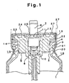
- Numeral 1 represents an inner sack, in which an opening 2 is formed at a top end of the inner sack and a flange 3 is extended from an outer periphery of the top end of the opening 2.
- the inner sack 1 is formed in a way capable of readily transforming in use of a sheet or film of a single layer of a material selected from ethylenevinylalcohol, polypropylene, polyacrylonitrile, polyethyleneterephthalate, high density polyethylene, low density polyethylene, straight-chain type low density polyethylene, and polyamide, which are soft and elastic.
- the inner sack 1 is formed in use of a sheet or film of multiple layers in which an ethylenevinylealcohol film is formed with polyethylene films provided on opposite sides of the ethylenevinylealcohol film.
- the sheet or film of multiple layers also be formed of an ethylenevinylealcohol film with polypropylene films provided on opposite sides of the ethylenevinylealcohol film.
- the sheet or film of multiple layers also be formed of multiple materials selected from ethylenevinylalcohol, polypropylene, polyacrylonitrile, polyethyleneterephthalate, high density polyethylene, low density polyethylene, straight-chain type low density polyethylene, polyamide, and so on.
- a housing 5 is disposed on the top end of the inner periphery 4 of the opening 2 of the inner sack 1.
- the housing 5 is made of a rigid resin material and is formed with a valve assembly 7 controlling spraying of aerosol contents at a mounting recess 6 provided at a center of the housing.
- the valve assembly 7 urges outwardly a stem 8 whose lower end is inserted in the mounting recess 6 by means of a coil spring 10 wound between a bottom of the mounting recess 6 and a lower end of the stem 8.
- This stem 8 is formed with a spraying route, not shown, with a bottom for guiding the aerosol contents in the vertical direction at the center of the stem 8, and an orifice 11 in communication with the spraying route is opened at a side of the stem 8.
- the orifice 11 is normally sealed by a stem gasket 12, and when the stem 8 is pressed in an inside direction of the mounting recess 6, the orifice 11 can be made open upon transforming the stem gasket 12.
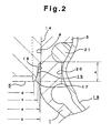
- the housing 5 has a ring-shaped brim 13 on a top end of an outer periphery of the housing 5, and an insertion contact portion 14 is arranged to closely contact with the top end 4 of the inner periphery of the opening 2 of the inner sack 1.
- a temporarily fitting portion 15 is formed in continuation of the lower end of the insertion contact portion 14.
- the insertion contact portion 14 of the housing 5 is mounted on the top end 4 of the inner periphery of the inner sack 1.
- an inner diameter (a) of the top end 4 of the inner periphery of the inner sack 1 is set to be 1
- an outer diameter (b) of the insertion contact portion 14 of the housing 5 in contacting with the inner sack 1 is set to be 1.02 to 0.98.
- the outer diameter (c) of the maximum portion 16 of the temporarily fitting portion 15 is set to be 0.97 to 0.95.
- the temporarily fitting portion 15 has a diameter smaller than the inner diameter (a) of the top end 4 of the inner periphery of the inner sack 1 and allows the housing 5 to be inserted in the top end 4 of the inner periphery of the inner sack 1 easily.
- the outer diameter (d) of the minimum portion 17 of the temporarily fitting portion 15 is set to 0.94 to 0.88, and the minimum portion 17 is formed at a lower position of the maximum portion 16. Also, where the inner diameter (a) of the top end 4 of the inner periphery of the inner sack 1 is set to be 1, the width (e) in up and down directions of the temporarily fitting portion 15 is required to be 0.10 to 0.19.
- the inner sack 1 is to be mounted inside a container body 18 made of a metal material, and the flange 3 extending outward is formed at the top end of the outer periphery.
- a ring-shaped gasket 21 is disposed between the lower surface of the flange 3 and the upper surface of a ring-shaped projection 20 extending upward of the container body 18. This ring-shaped gasket seals and keeps the space between the lower surface of the flange 3 of the inner sack 1 and the inner surface of the ring-shaped projection 20 of the container body 18.
- An upper gasket 22 is disposed between the top end of the inner sack 1 and the ring-shaped brim 13 arranged at the top end of the outer periphery of the housing 5.
- the upper gasket 22 prevents the propellant from leaking, which otherwise tends to leak outside between the outer periphery of the housing 5 and the inner surface of the inner sack 1.
- a ring-shaped lib 23 extends downward at the lower surface of the ring-shaped brim 13 for sealing well by pressing the top surface of the upper gasket 22.
- a planer lid 24 having a cross section in a rectangular U-shaped is formed of a metal material on a top surface and an outer periphery of the ring-shaped brim 13, thereby covering the top surface of the housing 5.
- the lid 24 has an opening 25 for the stem 8 at a center of the lid and projects the top end of the stem 8 from the opening 25 outward.
- a top edge 27 of the container body 18 is folded toward a top surface of the lid 24 and is secured, thereby surely securing the housing 5 to the container body 18.
- a portion of the ring-shaped brim 13 is pressed toward the flange 3 of the inner sack 1, thereby pressing the upper gasket 22 and the ring-shaped gasket 21 to improve sealing property.
- the inner sack 1 is mounted in the metal container body 18 to assemble the double chamber aerosol container.
- the flange 3 of the inner sack 1 is engaged with the top surface of the inner periphery of the ring-shaped projection 20 of the container body 18 through the ring-shaped gasket 21.
- the upper gasket 22 is subsequently disposed on the upper surface of the flange 3.
- the housing 5 is inserted in the opening 2 of the inner sack 1 from a direction of the temporarily fitting portion 15, and the insertion contact portion 14 formed at the outer periphery of the housing 5 is inserted and closely contacted with the top end of the inner periphery 4 of the opening 2 of the inner sack 1.
- the outer diameter (b) of the insertion contact portion 14 is set to be 1.02 to 0.98 where the inner diameter (a) of the top end 4 of the inner periphery of the inner sack 1 is set to be 1, the insertion contact portion 14 is in close contact with the top end of the inner periphery of the opening 2 of the inner sack 1, and the inner sack 1 cannot be broken or positionally moved when the housing 5 is inserted.
- the insertion contact portion 14 of the housing 5 is larger than 1.02, the insertion contact portion 14 of the housing 5 is inserted uneasily to the top end of the inner periphery of the inner sack 1, and the inner sack 1 may be moved upon hit within the container body 18 or may be broken when the insertion contact portion 14 is inserted.
- the outer diameter (b) of the insertion contact portion 14 of the housing 5 in contacting with the inner sack 1 is set smaller than 0.98, the insertion contact portion 14 of the housing 5 is inserted loosely to the top end 4 of the inner periphery of the inner sack 1.
- the inner sack 1 is axially shifted from the insertion contact portion 14 of the housing 5, and the inner sack 1 is contracted unevenly by means of the insertion contact portion 14 when the housing 5 is mounted in the container body 18, thereby causing leakage.
- intensity of such wrapping may become uneven, so that spraying gas may be leaked.
- the outer diameter (c) of the maximum portion 16 of the temporarily fitting portion is set to be 0.97 to 0.95, so that the housing 5 can be inserted easily to the top end 4 of the inner periphery of the inner sack 1.
- the outer diameter (c) of the maximum portion 16 of the temporarily fitting portion 15 is set larger than 0.97 where the inner diameter (a) of the top end 4 of the inner periphery of the inner sack 1 is set to be 1, the temporarily fitting portion 15 cannot be inserted smoothly in the top end 4 of the inner periphery of the inner sack 1, and therefore, when the temporarily fitting portion 15 is inserted in the top end 4 in the inner sack 1, the maximum portion 16 of the temporally fitting portion 15 may be caught to scratch the inner periphery of the top end of the inner sack 1, thereby creating causation for leakage.
- the outer diameter (c) of the maximum portion 16 of the temporarily fitting portion 15 is set smaller than 0.95, a gap unnecessary for insertion work is created between the top end 4 of the inner periphery of the inner sack 1 and the portion, so that the temporarily fitting portion 15 is inserted too loosely to the top end 4 of the inner periphery of the inner sack 1, and so that the inner sack 1 is axially shifted from the insertion contact portion 14 of the housing 5. Consequently, wrinkles may be generated at the temporarily fitting portion 15 where the housing 5 is mounted on the container body 18, and so that such wrinkles make uneven a contraction degree of the inner sack 1 by the insertion contact portion 14.
- the temporarily fitting portion 15 can serve as an introduction portion when the insertion contact portion 14 is inserted in the top end 4 of the inner periphery of the inner sack 1. This operation is, with respect to the above range, to prevent the inner sack 1 of the housing 5 from being caught or suffering from wrinkles.
- the outer diameter (d) of the minimum portion 17 of the temporarily fitting portion 15 is set larger than 0.94 where the inner diameter (a) of the top end 4 of the inner periphery of the inner sack is 1, the lower end of the temporally fitting portion 15 may be caught when the temporarily fitting portion 15 is inserted in the top end 4 of the inner sack 1, thereby possibly scratching the top end 4 of the inner periphery of the inner sack 1, and creating causation for leakage.
- the outer diameter (d) of the minimum portion 17 of the temporarily fitting portion 15 is set smaller than 0.87 where the inner diameter (a) of the top end of the inner periphery of the inner sack is 1, an unnecessary gap is created during insertion work between the top end 4 of the inner periphery of the inner sack 1 and the temporarily fitting portion 15 in the same manner as in the case that the maximum outer diameter (c) is made unnecessarily small.
- the temporarily fitting portion 15 is inserted too loosely into the top end 4 of the inner periphery of the inner sack 1, so that the inner sack 1 is axially shifted from the insertion contact portion 14 of the housing 5, so that wrinkles may be generated at the temporarily fitting portion 15 where the housing 5 is mounted on the container body 18, and so that such wrinkles make uneven a contraction degree of the inner sack 1 by the insertion contact portion.
- the width (e) in the up and down direction of the temporarily fitting portion 15 is set to be 0.19 to 0.10 where the inner diameter (a) of the top end 4 of the inner periphery of the inner sack 1 is 1, adequate sealing is guaranteed between the insertion contact portion 14 and the top end 4 of the inner periphery of the inner sack 1, and the insertion contact portion 14 is surely guided to the top end 4 of the inner periphery of the inner sack 1 without any problem.
- the width in the up and down direction of the temporarily fitting portion 15 is made larger than 0.19, the length of the insertion contact portion 14 of the housing 5 is made shorter, so that adequate sealing may not be obtained between the insertion contact portion 14 and the top end 4 of the inner periphery of the inner sack 1. If the width in the up and down direction of the temporarily fitting portion 15 is made shorter than 0.10, the insertion contact portion 14 may not be guided smoothly to the top end of the inner periphery of the inner sack 1.
- a proper button is coupled to the stem 8 and pressed. Upon this pressing, the stem 8 slides toward the bottom of the mounting recess 6 in opposing the coil spring 10, thereby transforming the stem gasket 12 and opening the orifice 11.
- the aerosol contents introduced in the spraying route from the orifice 11 is sprayed outside the nozzle or the like of the bottom.
- the stem 8 When the stem 8 is released from pressing, the stem 8 returns upward by return force of the coil spring 10, and spraying of the aerosol contents is stopped because the orifice 11 is sealed by the stem gasket 12.
- the above material forming the inner sack 1 permeates the propellant little by little.
- the propellant thus permeated though tries to leak out via a space between the container body 18 and the inner sack 1, is prevented from leaking outside because the ring-shaped gasket 21 is placed between the lower surface of the flange 3 of the inner sack 1 and the upper surface of the ring-shaped projection 20 of the container body 18, thereby never releasing outside the gas permeated through the inner sack 1.
- the upper gasket 22 also prevents the propellant from leaking out which otherwise leaks through a space between the outer periphery of the housing 5 and the inner periphery 1 of the inner sack 1. Therefore, even where the aerosol container is preserved for a long time, the propellant would not be dissipated through permeation, so that the aerosol container can do always good spraying of the aerosol contents.
- the lid 24 in which the metal plate is folded into a shape having the rectangular U-shaped cross section is placed on a top end of the housing 5, and the top edge 27 of the container body 18 is folded and secured to the top surface of the lid 24. Therefore, the aerosol container can be assembled readily. Since the container body 18 of the housing 5 is pressed inward in association with folding of the top edge 27, the top end of the flange 3 is surely in contact with the lower surface of the ring-shaped brim 13 via the upper gasket 22, and the lower surface of the flange 3 is surely in contact with the upper surface of the ring-shaped projection 20 via the ring-shaped gasket 21, so that the aerosol container can improve the sealing property further.
- the followings are prescriptions of respective contents where, in the inner sack 1 of the container body 18 thus formed, a soft type hair spray, hair foam, kerosene basis insecticide for air spraying, water basis insecticide for gardening, agent for permanently waving treatment, acidic hair dye, oxidizing two-agent type permanent hair dye, depilatory, or waterproofing agents, is filled.
- Soft Type Hair Spray Acrylic resin alkanol amine liquid (30%) 2.00 weight % Polyoxyethylene oleyl ether 0.01 weight % Perfume 0.17 weight % Denatured ethylalcohol 52.82 weight % Propellant LPG 45.00 weight % Total 100.00 weight % Hair Foam Denatured ethyl alcohol 9.00 weight % Cetyl alcohol 0.20 weight % Stearyl alcohol 0.20 weight % Methylpolysiloxyane-polyoxyalkylene copolymer 0.10 weight % Polyoxyethylenealkylether (E.O.13) 0.60 weight % Cationic cellulose 3.00 weight % Polyoxyethylenesorbitan monolauric acid (E.O.6) 0.40 weight % Hydrolysis collagen 0.40 weight % Glycerin 0.10 weight % Stearyltrimethylammoniumchloride 0.05 weight % Perfume 0.10 weight % Refined water 78.85 weight % Propellant LPG 7.00 weight % Total 10
- This invention is thus constituted, so that in the double chamber aerosol container in which the inner sack is mounted in the metal container body, the propellant is prevented from permeating outside and pressure of the aerosol container is prevented from lowering, and so that the aerosol container can spray the aerosol contents always in a good way even where subjected to a long term preservation or exhibition.
- the insertion contact portion of the housing is made larger than the diameter of the top end of inner periphery of the inner sack to improve contact between the insertion contact portion and the top end of the inner periphery, thereby preventing the inner sack from being broken, allowing the housing and the inner sack to be fitted precisely without inclining or moving the inner sack when the housing is mounted on the inner sack, and preventing leakage of air from occurring from a viewpoint of assembling.
Landscapes
- Chemical & Material Sciences (AREA)
- Dispersion Chemistry (AREA)
- Engineering & Computer Science (AREA)
- Mechanical Engineering (AREA)
- Containers And Packaging Bodies Having A Special Means To Remove Contents (AREA)
- Nozzles (AREA)
- Packages (AREA)
Applications Claiming Priority (2)
| Application Number | Priority Date | Filing Date | Title |
|---|---|---|---|
| JP10233307A JP2000062870A (ja) | 1998-08-19 | 1998-08-19 | 二重エアゾール容器 |
| JP23330798 | 1998-08-19 |
Publications (3)
| Publication Number | Publication Date |
|---|---|
| EP0980835A2 EP0980835A2 (en) | 2000-02-23 |
| EP0980835A3 EP0980835A3 (en) | 2002-01-09 |
| EP0980835B1 true EP0980835B1 (en) | 2004-03-03 |
Family
ID=16953079
Family Applications (1)
| Application Number | Title | Priority Date | Filing Date |
|---|---|---|---|
| EP98124586A Expired - Lifetime EP0980835B1 (en) | 1998-08-19 | 1998-12-23 | Double chamber aerosol container |
Country Status (4)
| Country | Link |
|---|---|
| US (1) | US6098846A (enExample) |
| EP (1) | EP0980835B1 (enExample) |
| JP (1) | JP2000062870A (enExample) |
| DE (1) | DE69822147T2 (enExample) |
Families Citing this family (21)
| Publication number | Priority date | Publication date | Assignee | Title |
|---|---|---|---|---|
| US20020035821A1 (en) * | 2000-09-22 | 2002-03-28 | Gilroy Gordon C. | Method of assembling aerosol container incorporating barrier pack |
| FR2830778B1 (fr) * | 2001-10-11 | 2004-07-09 | Oreal | Dispositif de pulverisation d'au moins un produit sur un support, notamment un support keratinique tel que la peau |
| US20020104898A1 (en) * | 2000-10-24 | 2002-08-08 | L'oreal | Spray device having at least two vector gas outlet orifices |
| FR2818101B1 (fr) * | 2000-12-15 | 2003-09-26 | Oreal | Dispositif pour la pulverisation d'un produit cosmetique |
| JP3803585B2 (ja) * | 2002-01-15 | 2006-08-02 | ホーユー株式会社 | 2重エアゾール容器及び2連缶容器 |
| GB0212047D0 (en) | 2002-05-24 | 2002-07-03 | Btg Int Ltd | Generation of therapeutic microfoam |
| US20030141322A1 (en) * | 2002-12-20 | 2003-07-31 | Joseph Groeger | Valve assembly for metered dose dispensers |
| EP1468759A1 (de) * | 2003-04-15 | 2004-10-20 | Nussbaum Rielasingen GmbH | Verfahren zum Herstellen eines Zweikammerdruckbehälters |
| GB0520930D0 (en) * | 2005-10-14 | 2005-11-23 | Reckitt Benckiser Uk Ltd | Composition and method of use |
| US20100001020A1 (en) * | 2008-07-02 | 2010-01-07 | Ashley Louis S | method of attaching a soft plastic bag in an aerosol can, and other cans such as flat top cans |
| JP5265051B2 (ja) * | 2010-12-02 | 2013-08-14 | 東洋エアゾール工業株式会社 | 複数液分配用のエアゾール装置 |
| KR101258142B1 (ko) * | 2011-06-30 | 2013-04-25 | (주)연우 | 내용물의 리필이 가능한 지관용기 |
| JP6313947B2 (ja) * | 2013-10-01 | 2018-04-18 | 株式会社ダイゾー | 複数内容物の吐出容器および複数内容物の吐出容器の製造方法 |
| JP6172756B2 (ja) * | 2014-04-30 | 2017-08-02 | 株式会社三谷バルブ | 内外二重容器エアゾール噴射機構およびこの内外二重容器エアゾール噴射機構を備えたエアゾール式製品 |
| JP6172751B2 (ja) * | 2013-12-03 | 2017-08-02 | 株式会社三谷バルブ | エアゾールハウジング機構およびこのエアゾールハウジング機構を備えたエアゾール式製品 |
| KR102005615B1 (ko) * | 2013-12-03 | 2019-07-30 | 가부시키가이샤 미타니 밸브 | 에어로졸 하우징 기구 및 이 에어로졸 하우징 기구를 구비한 에어로졸식 제품 |
| JP6823356B2 (ja) * | 2014-08-22 | 2021-02-03 | 武内プレス工業株式会社 | 二重エアゾール容器及びその製造方法 |
| KR101645651B1 (ko) * | 2014-10-07 | 2016-08-09 | 주식회사 톨모 | 이중 용기 구조를 갖는 분사장치의 내부용기 |
| US10596765B2 (en) * | 2017-05-16 | 2020-03-24 | The Procter & Gamble Company | Method of making an aerosol dispenser having annular seals and method of making an aerosol container therefor |
| EP3403948B1 (en) * | 2017-05-16 | 2022-11-30 | The Procter & Gamble Company | Container for aerosol dispenser, aerosol dispenser having a container and preform container for an aerosol dispenser |
| US10501258B2 (en) | 2017-05-26 | 2019-12-10 | The Procter & Gamble Company | Aerosol dispenser having annular seals and aerosol container therefor |
Family Cites Families (9)
| Publication number | Priority date | Publication date | Assignee | Title |
|---|---|---|---|---|
| US3662926A (en) * | 1971-01-19 | 1972-05-16 | Clayton Corp | Valve and bag assembly for pressure dispensing |
| US4457454A (en) * | 1981-10-26 | 1984-07-03 | Philip Meshberg | Two-compartment dispenser |
| JP2792691B2 (ja) * | 1989-11-30 | 1998-09-03 | 武内プレス工業株式会社 | 二重エアゾール容器のバリアパック |
| US5083681A (en) * | 1990-07-12 | 1992-01-28 | Nye Norman H | Valve for a fluid dispensing container |
| FR2685285B1 (fr) * | 1991-12-20 | 1995-04-14 | Givenchy Parfums | Procede de conditionnement d'un produit liquide quelconque et flacon obtenu par ce procede. |
| WO1995015895A1 (fr) * | 1993-12-06 | 1995-06-15 | Charles Kaeser | Boite d'aerosol rechargeable a propulsion d'air |
| DE4427175A1 (de) * | 1994-08-01 | 1996-02-08 | Coster Tecnologie Speciali Spa | Baueinheit |
| JP3543862B2 (ja) * | 1994-12-21 | 2004-07-21 | 東洋エアゾール工業株式会社 | 二重エアゾール容器 |
| GB2311982B (en) * | 1996-04-09 | 2000-03-08 | Bespak Plc | Improvements in or relating to valves for dispensers |
-
1998
- 1998-08-19 JP JP10233307A patent/JP2000062870A/ja active Pending
- 1998-12-21 US US09/216,729 patent/US6098846A/en not_active Expired - Lifetime
- 1998-12-23 DE DE69822147T patent/DE69822147T2/de not_active Expired - Lifetime
- 1998-12-23 EP EP98124586A patent/EP0980835B1/en not_active Expired - Lifetime
Also Published As
| Publication number | Publication date |
|---|---|
| JP2000062870A (ja) | 2000-02-29 |
| EP0980835A2 (en) | 2000-02-23 |
| HK1029317A1 (en) | 2001-03-30 |
| EP0980835A3 (en) | 2002-01-09 |
| DE69822147D1 (de) | 2004-04-08 |
| DE69822147T2 (de) | 2004-10-28 |
| US6098846A (en) | 2000-08-08 |
Similar Documents
| Publication | Publication Date | Title |
|---|---|---|
| EP0980835B1 (en) | Double chamber aerosol container | |
| US6196275B1 (en) | Double chamber aerosol container and manufacturing method therefor | |
| US6092566A (en) | Double chamber aerosol container and manufacturing method therefor | |
| JP2968944B2 (ja) | エアゾール容器用バルブ装置 | |
| JP3865485B2 (ja) | エアゾール容器用の流量調整装置 | |
| US9828170B2 (en) | Methods for manufacturing an aerosol product | |
| US6588631B2 (en) | System for dispensing a product | |
| EP3747800B1 (en) | Metering valve mechanism of aerosol container, and aerosol type product equipped with said metering valve | |
| CA2229950A1 (en) | Liquid dispensing pump having water seal | |
| JP5511064B2 (ja) | 定量噴射機構および、この定量噴射機構を備えたエアゾール式製品 | |
| JP4974175B2 (ja) | 流量レギュレータユニットおよびこの流量レギュレータユニットを備えたエアゾール式製品 | |
| JP2014037268A (ja) | トリガー操作式内容物放出機構ならびにこのトリガー操作式内容物放出機構を備えたエアゾール式製品およびポンプ式製品 | |
| JP4974174B2 (ja) | チップストップ機構,チップストップ機構を備えたポンプ式製品および、チップストップ機構を備えたエアゾール式製品 | |
| JP5408696B2 (ja) | シャットオフ機構,シャットオフ機構を備えたポンプ式製品およびシャットオフ機構を備えたエアゾール式製品、ならびにシャットオフ機構の組立方法 | |
| HK1029317B (en) | Double chamber aerosol container | |
| JP4702831B2 (ja) | チップストップ機構,チップストップ機構を備えたポンプ式製品および、チップストップ機構を備えたエアゾール式製品 | |
| JPH1072072A (ja) | 二重エアゾール容器 | |
| JPH11171270A (ja) | 蓋体固定構造および加圧式ディスペンサ製品 | |
| JP3895428B2 (ja) | エアゾール容器用の定量噴射装置 | |
| JP6210586B2 (ja) | エアゾール容器に取り付けられるマウンティングキャップおよびこのマウンティングキャップを備えたエアゾール式製品 | |
| WO2023080095A1 (ja) | 内容物噴射機構およびこの内容物噴射機構を備えたエアゾール式製品 | |
| JP2006160300A (ja) | 内容物放出機構およびそれを備えたエアゾール式製品 | |
| HK1029091B (en) | Double chamber aerosol container and manufacturing method therefor | |
| JP2006102690A (ja) | 容器内容物の放出量調整機構ならびにそれを備えたエアゾール式製品およびポンプ式製品 |
Legal Events
| Date | Code | Title | Description |
|---|---|---|---|
| PUAI | Public reference made under article 153(3) epc to a published international application that has entered the european phase |
Free format text: ORIGINAL CODE: 0009012 |
|
| AK | Designated contracting states |
Kind code of ref document: A2 Designated state(s): AT BE CH CY DE DK ES FI FR GB GR IE IT LI LU MC NL PT SE Kind code of ref document: A2 Designated state(s): CH DE FR GB IT LI |
|
| AX | Request for extension of the european patent |
Free format text: AL;LT;LV;MK;RO;SI |
|
| PUAL | Search report despatched |
Free format text: ORIGINAL CODE: 0009013 |
|
| AK | Designated contracting states |
Kind code of ref document: A3 Designated state(s): AT BE CH CY DE DK ES FI FR GB GR IE IT LI LU MC NL PT SE |
|
| AX | Request for extension of the european patent |
Free format text: AL;LT;LV;MK;RO;SI |
|
| 17P | Request for examination filed |
Effective date: 20020326 |
|
| 17Q | First examination report despatched |
Effective date: 20020626 |
|
| AKX | Designation fees paid |
Free format text: CH DE FR GB IT LI |
|
| GRAH | Despatch of communication of intention to grant a patent |
Free format text: ORIGINAL CODE: EPIDOS IGRA |
|
| GRAS | Grant fee paid |
Free format text: ORIGINAL CODE: EPIDOSNIGR3 |
|
| GRAA | (expected) grant |
Free format text: ORIGINAL CODE: 0009210 |
|
| AK | Designated contracting states |
Kind code of ref document: B1 Designated state(s): CH DE FR GB IT LI |
|
| REG | Reference to a national code |
Ref country code: GB Ref legal event code: FG4D |
|
| RIN1 | Information on inventor provided before grant (corrected) |
Inventor name: HOSHINO, KAZUNORI Inventor name: MITSUI, TOSHIYUKI Inventor name: YAZAWA, IWAO |
|
| REG | Reference to a national code |
Ref country code: CH Ref legal event code: EP |
|
| REG | Reference to a national code |
Ref country code: IE Ref legal event code: FG4D |
|
| REF | Corresponds to: |
Ref document number: 69822147 Country of ref document: DE Date of ref document: 20040408 Kind code of ref document: P |
|
| REG | Reference to a national code |
Ref country code: CH Ref legal event code: NV Representative=s name: TROESCH SCHEIDEGGER WERNER AG |
|
| ET | Fr: translation filed | ||
| REG | Reference to a national code |
Ref country code: HK Ref legal event code: GR Ref document number: 1029317 Country of ref document: HK |
|
| PLBE | No opposition filed within time limit |
Free format text: ORIGINAL CODE: 0009261 |
|
| STAA | Information on the status of an ep patent application or granted ep patent |
Free format text: STATUS: NO OPPOSITION FILED WITHIN TIME LIMIT |
|
| 26N | No opposition filed |
Effective date: 20041206 |
|
| REG | Reference to a national code |
Ref country code: FR Ref legal event code: PLFP Year of fee payment: 18 |
|
| REG | Reference to a national code |
Ref country code: FR Ref legal event code: PLFP Year of fee payment: 19 |
|
| REG | Reference to a national code |
Ref country code: FR Ref legal event code: PLFP Year of fee payment: 20 |
|
| PGFP | Annual fee paid to national office [announced via postgrant information from national office to epo] |
Ref country code: FR Payment date: 20171221 Year of fee payment: 20 Ref country code: DE Payment date: 20171211 Year of fee payment: 20 |
|
| PGFP | Annual fee paid to national office [announced via postgrant information from national office to epo] |
Ref country code: CH Payment date: 20171220 Year of fee payment: 20 Ref country code: GB Payment date: 20171221 Year of fee payment: 20 |
|
| PGFP | Annual fee paid to national office [announced via postgrant information from national office to epo] |
Ref country code: IT Payment date: 20171221 Year of fee payment: 20 |
|
| REG | Reference to a national code |
Ref country code: DE Ref legal event code: R071 Ref document number: 69822147 Country of ref document: DE |
|
| REG | Reference to a national code |
Ref country code: CH Ref legal event code: PL |
|
| REG | Reference to a national code |
Ref country code: GB Ref legal event code: PE20 Expiry date: 20181222 |
|
| PG25 | Lapsed in a contracting state [announced via postgrant information from national office to epo] |
Ref country code: GB Free format text: LAPSE BECAUSE OF EXPIRATION OF PROTECTION Effective date: 20181222 |