EP0980741B1 - Dispositif et procédé de distribution de suspension abrasive pour le polissage mécanique de substrat - Google Patents
Dispositif et procédé de distribution de suspension abrasive pour le polissage mécanique de substrat Download PDFInfo
- Publication number
- EP0980741B1 EP0980741B1 EP99401715A EP99401715A EP0980741B1 EP 0980741 B1 EP0980741 B1 EP 0980741B1 EP 99401715 A EP99401715 A EP 99401715A EP 99401715 A EP99401715 A EP 99401715A EP 0980741 B1 EP0980741 B1 EP 0980741B1
- Authority
- EP
- European Patent Office
- Prior art keywords
- abrasive
- distribution
- loop
- abrasive slurry
- pipes
- Prior art date
- Legal status (The legal status is an assumption and is not a legal conclusion. Google has not performed a legal analysis and makes no representation as to the accuracy of the status listed.)
- Expired - Lifetime
Links
- 238000009826 distribution Methods 0.000 title claims description 30
- 239000002002 slurry Substances 0.000 title claims description 18
- 238000005498 polishing Methods 0.000 title description 7
- 238000000034 method Methods 0.000 title description 4
- 239000000758 substrate Substances 0.000 title description 2
- IJGRMHOSHXDMSA-UHFFFAOYSA-N Atomic nitrogen Chemical compound N#N IJGRMHOSHXDMSA-UHFFFAOYSA-N 0.000 claims description 14
- 239000007789 gas Substances 0.000 claims description 13
- XLYOFNOQVPJJNP-UHFFFAOYSA-N water Chemical compound O XLYOFNOQVPJJNP-UHFFFAOYSA-N 0.000 claims description 9
- 229910052757 nitrogen Inorganic materials 0.000 claims description 7
- 239000008367 deionised water Substances 0.000 claims description 5
- 229910021641 deionized water Inorganic materials 0.000 claims description 5
- 238000011084 recovery Methods 0.000 claims description 5
- 239000011261 inert gas Substances 0.000 claims description 4
- 239000000725 suspension Substances 0.000 description 54
- VYPSYNLAJGMNEJ-UHFFFAOYSA-N Silicium dioxide Chemical compound O=[Si]=O VYPSYNLAJGMNEJ-UHFFFAOYSA-N 0.000 description 14
- 239000000377 silicon dioxide Substances 0.000 description 7
- 239000000126 substance Substances 0.000 description 7
- 235000012431 wafers Nutrition 0.000 description 6
- XUIMIQQOPSSXEZ-UHFFFAOYSA-N Silicon Chemical compound [Si] XUIMIQQOPSSXEZ-UHFFFAOYSA-N 0.000 description 5
- 229910052710 silicon Inorganic materials 0.000 description 5
- 239000010703 silicon Substances 0.000 description 5
- 230000033228 biological regulation Effects 0.000 description 4
- 230000007423 decrease Effects 0.000 description 4
- 238000012423 maintenance Methods 0.000 description 4
- 238000002156 mixing Methods 0.000 description 4
- PNEYBMLMFCGWSK-UHFFFAOYSA-N aluminium oxide Inorganic materials [O-2].[O-2].[O-2].[Al+3].[Al+3] PNEYBMLMFCGWSK-UHFFFAOYSA-N 0.000 description 3
- 239000000463 material Substances 0.000 description 3
- 238000005086 pumping Methods 0.000 description 3
- 239000000243 solution Substances 0.000 description 3
- 238000011144 upstream manufacturing Methods 0.000 description 3
- QGZKDVFQNNGYKY-UHFFFAOYSA-N Ammonia Chemical compound N QGZKDVFQNNGYKY-UHFFFAOYSA-N 0.000 description 2
- XKRFYHLGVUSROY-UHFFFAOYSA-N Argon Chemical compound [Ar] XKRFYHLGVUSROY-UHFFFAOYSA-N 0.000 description 2
- 238000005299 abrasion Methods 0.000 description 2
- 150000001875 compounds Chemical class 0.000 description 2
- 238000001514 detection method Methods 0.000 description 2
- 238000002955 isolation Methods 0.000 description 2
- 239000004065 semiconductor Substances 0.000 description 2
- 238000003860 storage Methods 0.000 description 2
- KRQUFUKTQHISJB-YYADALCUSA-N 2-[(E)-N-[2-(4-chlorophenoxy)propoxy]-C-propylcarbonimidoyl]-3-hydroxy-5-(thian-3-yl)cyclohex-2-en-1-one Chemical compound CCC\C(=N/OCC(C)OC1=CC=C(Cl)C=C1)C1=C(O)CC(CC1=O)C1CCCSC1 KRQUFUKTQHISJB-YYADALCUSA-N 0.000 description 1
- 206010053567 Coagulopathies Diseases 0.000 description 1
- 239000004743 Polypropylene Substances 0.000 description 1
- 230000002378 acidificating effect Effects 0.000 description 1
- 229910021529 ammonia Inorganic materials 0.000 description 1
- 229910052786 argon Inorganic materials 0.000 description 1
- 230000015556 catabolic process Effects 0.000 description 1
- 239000000919 ceramic Substances 0.000 description 1
- 230000035602 clotting Effects 0.000 description 1
- 230000015271 coagulation Effects 0.000 description 1
- 238000005345 coagulation Methods 0.000 description 1
- 238000007796 conventional method Methods 0.000 description 1
- 230000007547 defect Effects 0.000 description 1
- 230000002950 deficient Effects 0.000 description 1
- 238000006731 degradation reaction Methods 0.000 description 1
- 238000010790 dilution Methods 0.000 description 1
- 239000012895 dilution Substances 0.000 description 1
- 238000006073 displacement reaction Methods 0.000 description 1
- 238000001035 drying Methods 0.000 description 1
- 230000005484 gravity Effects 0.000 description 1
- 239000001307 helium Substances 0.000 description 1
- 229910052734 helium Inorganic materials 0.000 description 1
- SWQJXJOGLNCZEY-UHFFFAOYSA-N helium atom Chemical compound [He] SWQJXJOGLNCZEY-UHFFFAOYSA-N 0.000 description 1
- 238000011065 in-situ storage Methods 0.000 description 1
- 238000002347 injection Methods 0.000 description 1
- 239000007924 injection Substances 0.000 description 1
- 238000005259 measurement Methods 0.000 description 1
- 239000012528 membrane Substances 0.000 description 1
- 229910052751 metal Inorganic materials 0.000 description 1
- 239000002184 metal Substances 0.000 description 1
- 150000002739 metals Chemical class 0.000 description 1
- 239000000203 mixture Substances 0.000 description 1
- 230000005693 optoelectronics Effects 0.000 description 1
- 239000002245 particle Substances 0.000 description 1
- 239000004033 plastic Substances 0.000 description 1
- 229920001155 polypropylene Polymers 0.000 description 1
- -1 polytetrafluoroethylene Polymers 0.000 description 1
- 229920001343 polytetrafluoroethylene Polymers 0.000 description 1
- 239000004810 polytetrafluoroethylene Substances 0.000 description 1
- 238000010926 purge Methods 0.000 description 1
- 230000001105 regulatory effect Effects 0.000 description 1
- 238000007711 solidification Methods 0.000 description 1
- 230000008023 solidification Effects 0.000 description 1
- 239000007921 spray Substances 0.000 description 1
- 230000003068 static effect Effects 0.000 description 1
- 238000009827 uniform distribution Methods 0.000 description 1
Images

Classifications
-
- B—PERFORMING OPERATIONS; TRANSPORTING
- B24—GRINDING; POLISHING
- B24B—MACHINES, DEVICES, OR PROCESSES FOR GRINDING OR POLISHING; DRESSING OR CONDITIONING OF ABRADING SURFACES; FEEDING OF GRINDING, POLISHING, OR LAPPING AGENTS
- B24B57/00—Devices for feeding, applying, grading or recovering grinding, polishing or lapping agents
-
- B—PERFORMING OPERATIONS; TRANSPORTING
- B24—GRINDING; POLISHING
- B24B—MACHINES, DEVICES, OR PROCESSES FOR GRINDING OR POLISHING; DRESSING OR CONDITIONING OF ABRADING SURFACES; FEEDING OF GRINDING, POLISHING, OR LAPPING AGENTS
- B24B57/00—Devices for feeding, applying, grading or recovering grinding, polishing or lapping agents
- B24B57/02—Devices for feeding, applying, grading or recovering grinding, polishing or lapping agents for feeding of fluid, sprayed, pulverised, or liquefied grinding, polishing or lapping agents
-
- B—PERFORMING OPERATIONS; TRANSPORTING
- B24—GRINDING; POLISHING
- B24B—MACHINES, DEVICES, OR PROCESSES FOR GRINDING OR POLISHING; DRESSING OR CONDITIONING OF ABRADING SURFACES; FEEDING OF GRINDING, POLISHING, OR LAPPING AGENTS
- B24B37/00—Lapping machines or devices; Accessories
- B24B37/04—Lapping machines or devices; Accessories designed for working plane surfaces
-
- Y—GENERAL TAGGING OF NEW TECHNOLOGICAL DEVELOPMENTS; GENERAL TAGGING OF CROSS-SECTIONAL TECHNOLOGIES SPANNING OVER SEVERAL SECTIONS OF THE IPC; TECHNICAL SUBJECTS COVERED BY FORMER USPC CROSS-REFERENCE ART COLLECTIONS [XRACs] AND DIGESTS
- Y10—TECHNICAL SUBJECTS COVERED BY FORMER USPC
- Y10T—TECHNICAL SUBJECTS COVERED BY FORMER US CLASSIFICATION
- Y10T137/00—Fluid handling
- Y10T137/4673—Plural tanks or compartments with parallel flow
-
- Y—GENERAL TAGGING OF NEW TECHNOLOGICAL DEVELOPMENTS; GENERAL TAGGING OF CROSS-SECTIONAL TECHNOLOGIES SPANNING OVER SEVERAL SECTIONS OF THE IPC; TECHNICAL SUBJECTS COVERED BY FORMER USPC CROSS-REFERENCE ART COLLECTIONS [XRACs] AND DIGESTS
- Y10—TECHNICAL SUBJECTS COVERED BY FORMER USPC
- Y10T—TECHNICAL SUBJECTS COVERED BY FORMER US CLASSIFICATION
- Y10T137/00—Fluid handling
- Y10T137/4673—Plural tanks or compartments with parallel flow
- Y10T137/469—Sequentially filled and emptied [e.g., holding type]
-
- Y—GENERAL TAGGING OF NEW TECHNOLOGICAL DEVELOPMENTS; GENERAL TAGGING OF CROSS-SECTIONAL TECHNOLOGIES SPANNING OVER SEVERAL SECTIONS OF THE IPC; TECHNICAL SUBJECTS COVERED BY FORMER USPC CROSS-REFERENCE ART COLLECTIONS [XRACs] AND DIGESTS
- Y10—TECHNICAL SUBJECTS COVERED BY FORMER USPC
- Y10T—TECHNICAL SUBJECTS COVERED BY FORMER US CLASSIFICATION
- Y10T137/00—Fluid handling
- Y10T137/4673—Plural tanks or compartments with parallel flow
- Y10T137/4807—Tank type manifold [i.e., one tank supplies or receives from at least two others]
Definitions
- the present invention relates to a device distribution of abrasive suspension for the mechanical polishing of substrates (see for example US-A-5,722,447).
- silica or alumina suspension for polishing the silicon wafers on the back side as well as the front side tends to generalize in the semiconductor, optoelectronics and optics. This naturally poses the problem of distribution of this product, from the delivery keg to several points of use.
- Such suspensions may also be used to polish a metallic layer already deposited on the silicon wafer; in this cases, these suspensions may have characteristics physical or chemical different from the first.
- a device which first comprises a measuring container in which are brought in turn the different chemicals used in the abrasive suspension, said chemicals being dosed in this container of measurement, each chemical compound then being, after measure, sent to a mixing container in which in situ mixing all the compounds of the suspension, this mixing container itself being connected to a mixing container negative pressure or vacuum so as to suck up the suspension which is in the container of mix and send it to the different delivery stations of the abrasive suspension.
- the apparatus according to the invention includes the features of claim 1.
- a distribution loop at the point of use consisting of a plurality of loops arranged in parallel with preferably each loop comprising at least one arm common to all loops, at one end of which are connected one ends of the plurality of loops.
- this loop will have two common arms connected by their respective first ends to a pluralities of sub-loops connected in parallel, the first common arm being by its second end at abrasive suspension tank and the second common arm being connected by its second end to means of recovery of the abrasive suspension.
- the length of each pipe (whatever the loop) between the tank and the point of distribution of the suspension will be roughly the same while the length of each pipe between the distribution point and means of recovery of the abrasive suspension will also preferably be much the same.
- regulation means on the device according to the invention and these means of regulation will be preferably either means of regulating the pressure of the abrasive suspension in the pipes, i.e. means of adjusting the suspension flow abrasive in said pipes (or possibly two in combination).
- We will preferably choose a minimum circulation speed in pipes of distribution to avoid deposit of abrasive suspension on the walls of the distribution pipes which would cause blockage of the pipes. It is indeed one of the important contributions of the invention than to avoid this way the plugging of the pipes which is a major problem in the facilities currently known.
- the speed of circulation will be between approximately 0.5 m / s and approximately 2 m / s and more preferably between about 1 and 1.2 m / s.
- each of the two pumps preferably only operating at approximately (and at plus) 50% of their power which allows in case one of the two pumps fails to continue normal operation of the device with a single pump which will then operate at 100% of its power.
- an alarm which will indicate when one of the pumps is blocked, defective or when the material flow leaving one of the pumps is substantially zero.
- circulation of the suspension will be provided by pressurized gas, preferably an inert gas such as nitrogen and / or argon and / or pressurized helium. It was found in this case however, there may still be a blockage of pipes. The Applicant has demonstrated that these blockages, in the case of circulation using gas under pressure, could be avoided by ensuring hygrometry minimum pressure gas used for circulation.
- pressurized gas preferably an inert gas such as nitrogen and / or argon and / or pressurized helium.
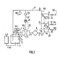
- a tank 1 contains a suspension abrasive 2 removed by a pipe 3 which crosses the tank wall 1 at point 4 and extends to two pumps 5 and 6 placed in parallel on this pipeline whose outputs are reconnected again together on the pipe 7 connected to the filter 8 which leads to line 9.
- the pipes 20 are respectively connected, 21, ... 22, of which the other ends respectively 30, 31, ... 32, are interconnected with line 40 of abrasive suspension return to tank 1, this pipe 40 crossing at 41 the wall of said tank to enter suspension 2 contained in this tank 1.
- a filling tank 42 is arranged in parallel with the tank 1 and connected to it by a line 43 so as to maintain, in all circumstances, a level always above a certain predetermined minimum in tank 1. This tank appendix 42 allows in particular to adjust the viscosity of the abrasive suspension.
- pressurized gas 44 such as an inert gas, preferably nitrogen, of a purity compatible with the desired application, in particular a purity of the N50 type or better.
- pressurized gas 44 such as an inert gas, preferably nitrogen
- B, C, ... D distributions, respectively B, C, ... D, of abrasive suspension at the points of use, respectively 60, 61, .. .62 via valves 70, 71, ... 72 respectively.
- the apparatus also comprises, between point 32 and point 41 of line 40, a pressure detector 80 electrically connected to a PID type regulation system (proportional / integral / differential) which is itself electrically connected, respectively by the lines 83 and 84 at the pumps, respectively 5 and 6.
- PID type regulation system proportional / integral / differential
- the pressure must be maintained at a pressure equal to the set pressure set in the PID, and when the pressure detected by 80 is lower than the pressure displayed, an electrical signal is generated by PID 81 so as to increase the pumping pressure of pumps 5 and 6.
- the pressure measured by the pressure detector 80 becomes equal to or greater than the pressure displayed in PID 81, the latter corrects the signal sent by the lines 83 and 84 to pumps 5 and 6 so as to reduce the pumping pressure of pumps 5 and 6 to the value corresponding to the pressure setpoint.
- the PID decreases the pumping pressure of the pumps by sending an adequate electrical signal to pumps 5 and 6 if the pressure detectors detect a pressure higher than the set pressure displayed in the PID 81.
- the apparatus may also include a regulation of flow either alone (without the pressure detection system with the PID), or in addition to the detection system pressure.
- This flow control system consists of in particular to measure the flow rate of the solution of the abrasive suspension and compare the measured value to a setpoint then increase or decrease the flow pumps 5 and 6 by sending an electrical signal corresponding to the said pumps after comparing the flow measured and the displayed flow rate.
- FIG 2 is shown an alternative embodiment of the device of the Figure 1 in which in particular at least two are used abrasive suspension storage tanks connected in parallel and which are used alternately as well when a tank is empty and this state is detected by a level detector, for example, we can automatically start the second tank without having need to interrupt abrasive suspension circulation which avoids clotting and clogging problems pipes, which therefore reduces the maintenance of the device. (In this figure 2, the same devices as those of Figure 1 have the same references).
- the two pipes 101 meet and 119 respectively connected to the suspension tanks abrasive 112 and 115 by means of the controlled opening 103 and 102 respectively, pipes 113 and 118.
- the tank 112 is under pressure from inert gas, for example nitrogen (ultra pure, of “electronic” purity for use suspension for polishing silicon wafers ("Wafer”)) under a pressure for example of around 3 bar in the space 114 above the suspension 127.
- the suspended supply when 112 is empty is done via valve 111 (open for filling, then closed in use - see below) and the pipeline 128 which plunges into 129 in the reserve 130 in the tank back 131.
- the lower part of the tank 115 is connected via line 117, valve 116 and the line 120 to line 128 so as to fill 115 when it is empty (valve 116 open and 111 closed) and fill in 112 when 111 is open 116 is closed (or fill in neither when 111 and 116 are closed).
- the pressurized nitrogen source 121 makes it possible to adjust gas pressures above the suspension via respectively the valves controlled (by a device of control well known to those skilled in the art "Proportional” (P), “Integral” (I), “Differential” (D) or “PID” 81) 108 and 110 allowing set pressures at for example 3 bar (relative) at above 127 (to push the suspension in 113) and at 0 bar (relative) in 115 to allow filling of 115 in suspension.
- 121 is also connected via the pipeline 131 and the controlled valve 122 (also controlled or not by PID 81) which maintains nitrogen pressure by example of 0.5 bar (relative) above the suspension 130.
- a large capacity tank 132 is provided which supplies 131 via line 124.
- This reservoir 132 can be raised to feed others gravity tanks (possibly you can also inject ultra-pure nitrogen pressure at the top through line 125). This mode of transport without pump but by gas pressure avoids the problem of seizure of pumps.
- the tank 2 is of sufficient volume to preferably provide autonomy to the equipment of the order of 2.5 / 3 days; it is preferably mechanically agitated continuously and maintained at slight overpressure (1 to 3 mbar) so as to avoid the action of atmospheric CO 2 on the ammonia contained in certain abrasive suspensions.
- the tank is made of a plastic material on which the solidifying silica or alumina are not likely to adhere.
- the withdrawal of the tank is preferably carried out by a bottom valve; the loop is returned by a valve descending below the minimum level of the tank.
- the tank is filled using a positive displacement pump from shuttle drums. If necessary, a water dilution must be carried out by injecting water and a silica suspension continuously into a static mixer. After each unloading of the shuttle drum 42, the silica supply circuit of the storage tank, pumps and pipe included is purged with deionized water.
- each pump preferably being connected to a variable frequency power supply 0-100 Hz controllable by a current (for example, from 4 to 20 mA); the 2 power supplies variable frequency are controlled by a PID 81 regulator at the pressure at the end of the loop just before the valve setting.
- the shaft of each pump should preferably be fitted with 2 seals, the space (bell) between the seals being kept at overpressure relative to the silica by injection of deionized water.
- the deionized water supply circuit will have at its inlet an orifice calibrated at 100-200 l / h and 10-20 l / h at the outlet.
- the pressure prevailing in the bell must be constant, if there is no leakage on the interior lining in contact with the silica. On the other hand, if there is a leak, the pressure in the bell between the 2 linings will gradually decrease and a pressure sensor will transmit alarm signals and organize a curative action.
- an automatic purge of the pumps with deionized water will also be provided in the event of a stop.
- the loop (in its common arm 7, 9) is equipped with a filter 8 preferably of “polypropylene” type preferably fixing at least 90% of the materials of size greater than about 100 micrometers. Given the character of this suspension, we will have to oversize this filter in order to work with a reduced differential pressure, from 0.1 to 0.2 bar.
- the diameter of the calibrated orifices is a function of number of parameters, such as the flow of the loop, loop pressure, number of devices to be serve, the viscosity of the suspension to be distributed, elements that the skilled person will be able to choose without difficulties in ensuring flow velocities, preferably between 0.2 and 0.5 m / s to minimize abrasion of the pipes.
- the distribution loop preferably includes a non-controlled control valve (not shown on the figure) resistant to abrasion and upstream of it, a flow meter 90 and a pressure sensor 80.
- the flow rate is adjusted using the control valve not subject to the selected value.
- the pressure setpoint is displayed on the PID 81 controller whose parameters are adjusted to obtain satisfactory operation of the loop, especially during small variations in pressure during withdrawal, start-up, and / or start-up operating on 1 pump.
- the system described above can also work in particular with pneumatic pumps membranes or bellows, commonly used in industry semiconductors, provided that the working gas is injected by a pilot-operated valve or a device of the type mass flow controller, controlled by a setpoint pressure given by a pressure regulator. In this case, operation with 2 pumps parallel to half flow nominal will be maintained so as to obtain a rate of high availability.
Landscapes
- Engineering & Computer Science (AREA)
- Mechanical Engineering (AREA)
- Grinding-Machine Dressing And Accessory Apparatuses (AREA)
- Finish Polishing, Edge Sharpening, And Grinding By Specific Grinding Devices (AREA)
- Air Transport Of Granular Materials (AREA)
Description
l'arbre de chaque pompe sera de préférence équipé de 2 garnitures d'étanchéité, l'espace (cloche) compris entre les garnitures d'étanchéité étant maintenu en surpression par rapport à la silice par injection d'eau désionisée. Le circuit d'alimentation en eau désionisée comportera à son entrée un orifice calibré à 100-200 l/h et 10-20 l/h en sortie. La pression régnant dans la cloche doit être constante, s'il n'y a pas de fuite sur la garniture intérieure en contact avec la silice. Par contre, s'il y a fuite, la pression régnant dans la cloche entre les 2 garnitures va baisser progressivement et un capteur de pression permettra de transmettre des signaux d'alarme et d'organiser une action curative. De préférence, on prévoira également une purge automatique des pompes à l'eau désionisée en cas d'arrêt.
- usure limitée en milieu abrasif grâce au faible régime de rotation des pompes,
- l'utilisation de 2 pompes permet de maintenir le débit et la pression de la boucle en cas de défaillance d'une à pompe, la seconde augmentant automatiquement son régime pour compenser.
- en cas de soutirage important, la pression au retour à la cuve baissant, les pompes augmentent leur régime pour maintenir le débit constant. Si, par exemple, les équipements soutirent plus que le débit nominal de la boucle, il y a compensation automatique et le débit de la boucle n'est jamais arrêté. Inversement, lorsque les soutirages s'arrêtent, la pression aura tendance à augmenter et le régulateur PID réduira la fréquence de commande des pompes. Les variations de pression dans le réseau de distribution sont aussi de faible amplitude, par exemple, ± 100 g ce qui est important pour le dosage de la solution abrasive sur les équipements de polissage.
- répartir le débit dans les différentes branches du réseau de manière égale,
- le soutirage de chaque équipement (distribution) qui s'effectue par un té en amont de l'orifice ne provoque pas de cette manière de baisse de pression significative.
Claims (16)
- Appareil de distribution de suspensions abrasives comportant:caractérisé en ce que la boucle de distribution au point d'utilisation est constituée d'une pluralité de boucles (20, 21, 22,...) connectées en parallèle, présentant sensiblement la même perte de charge.un réservoir (1) contenant une suspension abrasive (2),une boucle de distribution (3, 7, 9, 40) de la suspension abrasive (2)reliée au réservoir (1),des moyens de circulation (5, 6) pour faire circuler la suspension abrasive dans la boucle et assurer son retour dans le réservoir,des moyens de récupération (1) pour récupérer la suspension abrasive après circulation dans la boucle,des moyens de régulation (81) des moyens de circulation de manière à maintenir une circulation continue de la suspension,
- Appareil selon le revendication 1, caractérisé en ce que la boucle comporte au moins un bras commun (3, 7, 9) à toutes les boucles à l'une des extrémités duquel sont reliées l'une des extrémités de la pluralité de boucles.
- Appareil selon la revendication 2, caractérisé en ce que la boucle comporte deux bras communs, un premier bras (3, 7, 9) relié à une première extrémité au réservoir (1), et un second bras (40) relié à une première extrémité à des moyens de récupération (1).
- Appareil selon l'une des revendications 1 à 3 caractérisé en ce que la longueur de chaque canalisation entre le réservoir (1) et le point de distribution de la solution abrasive est sensiblement la même.
- Appareil selon l'une des revendications 1 à 4, caractérisé en ce que les longueurs de chaque canalisation entre le point de distribution (60, 61, 62) et les moyens de récupération (9) est sensiblement la même.
- Appareil selon l'une des revendications 1 à 5, caractérisé en ce qu'il comporte des moyens de régulation (80, 81) de la circulation de la solution abrasive dans la boucle par contrôle de la pression dans les canalisations de distribution de ladite solution.
- Appareil selon l'une des revendications 1 à 6, caractérisé en ce qu'il comporte des moyens de régulation du débit de la solution abrasive dans les différents bras de la boucle de distribution.
- Appareil selon l'une des revendications 1 à 7, caractérisé en ce que la suspension abrasive a une vitesse de circulation minimum dans les différentes canalisations de distribution afin d'éviter les dépôts de suspension sur les parois desdites canalisations de distribution.
- Appareil selon l'une des revendications 1 à 8, caractérisé en ce que la vitesse de distribution de la solution dans les canalisations est supérieure ou égale à environ 0,2 m/s.
- Appareil selon l'une des revendications 1 à 9, caractérisé en ce que la vitesse de circulation de la suspension abrasive dans les canalisations est inférieure ou égale à environ 10 m/s.
- Appareil selon l'une des revendications 1 à 10, caractérisé en ce que la vitesse de distribution de suspensions abrasives est de préférence comprise entre 0,5 et 2 m/s.
- Appareil selon la revendications 11, caractérisé en ce que la vitesse de distribution de suspensions abrasives est comprise entre environ 1 m/s et 1,2 m/s.
- Appareil selon l'une des revendications 11, caractérisé en ce que les moyens de circulation de suspensions abrasives sont constitués par au moins une pompe (5, 6).
- Appareil selon l'une des revendications 1 à 13, caractérisé en ce que les moyens de circulation de suspensions abrasives sont constitués par deux pompes (5, 6) montées en parallèle, chacune d'entre-elles fonctionnant à pas plus de 50% de sa puissance afin de permettre un fonctionnement normal de la distribution de suspensions abrasives si l'une des deux pompes tombe en panne.
- Appareil selon l'une des revendications 1 à 14, caractérisé en ce que les moyens de circulation (44) sont constitués par un gaz sous pression, notamment un gaz inerte tel que l'azote.
- Appareil selon la revendication 15, dans lequel les moyens de circulation sont constitués par un gaz sous pression caractérisé en ce qu'il comporte également des moyens pour créer une nébulisation d'eau désionnisée dans le gaz sous pression afin d'éviter le colmatage des filtres dans le système de distribution de la suspension abrasive.
Applications Claiming Priority (2)
| Application Number | Priority Date | Filing Date | Title |
|---|---|---|---|
| FR9810508 | 1998-08-18 | ||
| FR9810508A FR2782506B1 (fr) | 1998-08-18 | 1998-08-18 | Dispositif et procede de distribution de suspension abrasive pour le polissage mecanique de substrat |
Publications (2)
| Publication Number | Publication Date |
|---|---|
| EP0980741A1 EP0980741A1 (fr) | 2000-02-23 |
| EP0980741B1 true EP0980741B1 (fr) | 2002-11-13 |
Family
ID=9529747
Family Applications (1)
| Application Number | Title | Priority Date | Filing Date |
|---|---|---|---|
| EP99401715A Expired - Lifetime EP0980741B1 (fr) | 1998-08-18 | 1999-07-08 | Dispositif et procédé de distribution de suspension abrasive pour le polissage mécanique de substrat |
Country Status (9)
| Country | Link |
|---|---|
| US (1) | US6125876A (fr) |
| EP (1) | EP0980741B1 (fr) |
| JP (1) | JP4970635B2 (fr) |
| KR (1) | KR100601812B1 (fr) |
| CN (1) | CN1139106C (fr) |
| DE (1) | DE69903893T2 (fr) |
| FR (1) | FR2782506B1 (fr) |
| SG (1) | SG75972A1 (fr) |
| TW (1) | TW411289B (fr) |
Families Citing this family (26)
| Publication number | Priority date | Publication date | Assignee | Title |
|---|---|---|---|---|
| US6561381B1 (en) * | 2000-11-20 | 2003-05-13 | Applied Materials, Inc. | Closed loop control over delivery of liquid material to semiconductor processing tool |
| US6736154B2 (en) * | 2001-01-26 | 2004-05-18 | American Air Liquide, Inc. | Pressure vessel systems and methods for dispensing liquid chemical compositions |
| US7334708B2 (en) * | 2001-07-16 | 2008-02-26 | L'air Liquide, Societe Anonyme A Directoire Et Conseil De Surveillance Pour L'etude Et L'exploitation Des Procedes Georges Claude | Integral blocks, chemical delivery systems and methods for delivering an ultrapure chemical |
| EP1318306B1 (fr) * | 2001-12-04 | 2005-06-01 | Levitronix LLC | Dispositif de distribution de liquid |
| ATE296958T1 (de) * | 2001-12-04 | 2005-06-15 | Levitronix Llc | Abgabevorrichtung für ein fluid |
| US20040197731A1 (en) * | 2003-03-27 | 2004-10-07 | Swan Keith Daniel | Dental abrasive system using helium gas |
| JP4852323B2 (ja) | 2006-03-07 | 2012-01-11 | 株式会社荏原製作所 | 液供給方法、液供給装置、基板研磨装置、液供給流量測定方法 |
| US8507382B2 (en) * | 2007-12-06 | 2013-08-13 | Foresight Processing, Llc | Systems and methods for delivery of fluid-containing process material combinations |
| CN102248489B (zh) * | 2010-05-21 | 2013-05-29 | 中芯国际集成电路制造(上海)有限公司 | 一种脉动缓冲器及研磨液供应系统 |
| CN102806526A (zh) * | 2011-05-31 | 2012-12-05 | 无锡华润上华半导体有限公司 | 研磨液供应系统 |
| CN103522171B (zh) * | 2012-07-05 | 2016-04-06 | 上海华虹宏力半导体制造有限公司 | 一种用于抛光垫研磨盘的氮气输送装置 |
| US9770804B2 (en) | 2013-03-18 | 2017-09-26 | Versum Materials Us, Llc | Slurry supply and/or chemical blend supply apparatuses, processes, methods of use and methods of manufacture |
| US9841010B2 (en) * | 2014-02-14 | 2017-12-12 | Stephen B. Maguire | Method and apparatus for closed loop automatic refill of liquid color |
| JP6450650B2 (ja) * | 2015-06-16 | 2019-01-09 | 東京エレクトロン株式会社 | 処理装置、処理方法および記憶媒体 |
| JP6562396B2 (ja) * | 2015-07-17 | 2019-08-21 | 大成建設株式会社 | 電池電極スラリー分配装置、電池電極スラリー処理装置、電池電極スラリー分配方法、懸濁液分配装置、および懸濁液分配方法 |
| CN108274396B (zh) * | 2017-12-26 | 2020-06-12 | 中国科学院长春光学精密机械与物理研究所 | 一种用于光学研抛浆料供给的低速液流控制装置及方法 |
| JP7064979B2 (ja) * | 2018-06-25 | 2022-05-11 | 株式会社荏原製作所 | 流体の漏洩を確認する方法、および研磨装置 |
| JP6538954B1 (ja) * | 2018-12-11 | 2019-07-03 | 株式会社西村ケミテック | 研磨液供給装置 |
| JP6538952B1 (ja) * | 2018-12-11 | 2019-07-03 | 株式会社西村ケミテック | 研磨液供給装置 |
| CN109696802B (zh) * | 2019-01-16 | 2024-05-07 | 宁波南大光电材料有限公司 | 一种溶剂生产设备、溶剂制备及取用方法 |
| JP6887693B2 (ja) * | 2019-07-16 | 2021-06-16 | エリーパワー株式会社 | 循環装置、処理装置および電池電極スラリーの循環方法 |
| JP7403998B2 (ja) * | 2019-08-29 | 2023-12-25 | 株式会社荏原製作所 | 研磨装置および研磨方法 |
| JP7583383B2 (ja) * | 2021-05-12 | 2024-11-14 | 株式会社西村ケミテック | 薬液供給装置及び薬液供給方法 |
| CN114102439B (zh) * | 2021-11-23 | 2024-01-09 | 大连大学 | 智能芯片化学研磨液供给方法 |
| KR102431849B1 (ko) * | 2022-01-21 | 2022-08-12 | 웨스글로벌 주식회사 | 씨엠피 슬러리 혼합 및 공급 제어 시스템 |
| EP4463535A4 (fr) * | 2022-02-01 | 2025-09-10 | Univ Sydney | Système et procédé de pompage d'un fluide à travers une unité cible |
Family Cites Families (6)
| Publication number | Priority date | Publication date | Assignee | Title |
|---|---|---|---|---|
| JPS6317649Y2 (fr) * | 1985-04-24 | 1988-05-18 | ||
| US5148945B1 (en) * | 1990-09-17 | 1996-07-02 | Applied Chemical Solutions | Apparatus and method for the transfer and delivery of high purity chemicals |
| US5503139A (en) * | 1994-02-02 | 1996-04-02 | Mcmahon; Michael D. | Continuous flow adaptor for a nebulizer |
| US5722447A (en) * | 1994-04-29 | 1998-03-03 | Texas Instruments Incorporated | Continuous recirculation fluid delivery system and method |
| WO1996002319A2 (fr) * | 1994-07-19 | 1996-02-01 | Applied Chemical Solutions, Inc. | Appareil et procede de melange de produits chimiques en suspension |
| KR19980064179A (ko) * | 1996-12-19 | 1998-10-07 | 윌리엄비.켐플러 | 웨이퍼 연마 공정시 실리콘 제거율을 안정화하는 방법 |
-
1998
- 1998-08-18 FR FR9810508A patent/FR2782506B1/fr not_active Expired - Lifetime
- 1998-12-29 US US09/223,497 patent/US6125876A/en not_active Expired - Lifetime
-
1999
- 1999-07-08 EP EP99401715A patent/EP0980741B1/fr not_active Expired - Lifetime
- 1999-07-08 SG SG1999003470A patent/SG75972A1/en unknown
- 1999-07-08 DE DE69903893T patent/DE69903893T2/de not_active Expired - Fee Related
- 1999-07-29 TW TW088112864A patent/TW411289B/zh not_active IP Right Cessation
- 1999-08-11 CN CNB991117875A patent/CN1139106C/zh not_active Expired - Lifetime
- 1999-08-17 JP JP23031099A patent/JP4970635B2/ja not_active Expired - Lifetime
- 1999-08-18 KR KR1019990034072A patent/KR100601812B1/ko not_active Expired - Lifetime
Also Published As
| Publication number | Publication date |
|---|---|
| CN1247381A (zh) | 2000-03-15 |
| JP4970635B2 (ja) | 2012-07-11 |
| DE69903893D1 (de) | 2002-12-19 |
| TW411289B (en) | 2000-11-11 |
| US6125876A (en) | 2000-10-03 |
| EP0980741A1 (fr) | 2000-02-23 |
| KR100601812B1 (ko) | 2006-07-19 |
| JP2000071173A (ja) | 2000-03-07 |
| CN1139106C (zh) | 2004-02-18 |
| DE69903893T2 (de) | 2003-10-09 |
| FR2782506B1 (fr) | 2000-09-22 |
| KR20000017362A (ko) | 2000-03-25 |
| FR2782506A1 (fr) | 2000-02-25 |
| SG75972A1 (en) | 2000-10-24 |
Similar Documents
| Publication | Publication Date | Title |
|---|---|---|
| EP0980741A1 (fr) | Dispositif et procédé de distribution de suspension abrasive pour le polissage mécanique de substrat | |
| EP1438246B1 (fr) | Systeme de repartition de matiere pulverulente avec debits ponderaux controles | |
| CA1281948C (fr) | Procede et dispositif pour le dosage de matieres pulverulentes | |
| EP2678120B1 (fr) | Installation et procede pour le depot d'un film de particules ordonnees sur un substrat en defilement | |
| FR2878453A1 (fr) | Dispositif de fourniture de vapeurs d'un precurseur solide a un appareil de traitement | |
| FR2692597A1 (fr) | Procédé et appareil pour introduire des réactifs en phase liquide dans un réacteur chimique, et application au dépôt chimique en phase vapeur d'un revêtement sur un substrat. | |
| EP1235753A1 (fr) | Procede et installation de clarification des liquides et suspensions par floculation lestee et decantation | |
| EP0190082A1 (fr) | Dispositif de distribution à débit régulé d'une matière pulvérulente fluidisable | |
| FR2528082A1 (fr) | Recipient distributeur de detergent, notamment pour le reservoir a detergent d'une machine a laver automatique | |
| FR2790253A1 (fr) | Systeme de distribution de liquide et son utilisation pour la distribution d'un liquide ultra-pur | |
| EP1844859B1 (fr) | Dispositif de dosage et de transport en continu de produit pulvérulent | |
| EP0899008A1 (fr) | Dispositif de déchargement d'un récipient sous pression | |
| FR2566752A1 (fr) | Appareillage pour la recuperation de boue du fond d'un silo de stockage | |
| FR2463397A1 (fr) | Appareil pour la distribution automatique de poudre de laitier dans les lingotieres de coulee continue | |
| US20240189784A1 (en) | Dynamic wetting head | |
| CA2362710C (fr) | Pompe a lixiviat et de depollution, pneumatique, a vanne a manchon | |
| EP3038761B1 (fr) | Installation et procede a rendement ameliore de formation d'un film compact de particules a la surface d'un liquide porteur | |
| JP2642450B2 (ja) | 処理装置 | |
| FR2723005A1 (fr) | Dispositif de distribution de liquide par gravite et dispositif d'enduction photographique | |
| WO2025202490A1 (fr) | Dispositif de dessalement continu d'eau de mer en circuit fermé | |
| WO2010004113A1 (fr) | Système d'introduction de mortier dans un conteneur | |
| WO2022003268A1 (fr) | Dispositif pour le dépôt chimique en phase vapeur en lit fluidisé | |
| FR2691724A1 (fr) | Installation centrale de distribution de quantités de produits pulvérulents. | |
| WO2009150384A2 (fr) | Machine de traitement de récipients en matériau thermoplastique | |
| EP0565581A1 (fr) | Dispositif pour alimenter sous pression un poste de couchage photographique. |
Legal Events
| Date | Code | Title | Description |
|---|---|---|---|
| PUAI | Public reference made under article 153(3) epc to a published international application that has entered the european phase |
Free format text: ORIGINAL CODE: 0009012 |
|
| AK | Designated contracting states |
Kind code of ref document: A1 Designated state(s): DE GB IT NL |
|
| AX | Request for extension of the european patent |
Free format text: AL;LT;LV;MK;RO;SI |
|
| 17P | Request for examination filed |
Effective date: 20000823 |
|
| AKX | Designation fees paid |
Free format text: DE GB IT NL |
|
| 17Q | First examination report despatched |
Effective date: 20010710 |
|
| GRAG | Despatch of communication of intention to grant |
Free format text: ORIGINAL CODE: EPIDOS AGRA |
|
| GRAG | Despatch of communication of intention to grant |
Free format text: ORIGINAL CODE: EPIDOS AGRA |
|
| GRAH | Despatch of communication of intention to grant a patent |
Free format text: ORIGINAL CODE: EPIDOS IGRA |
|
| GRAH | Despatch of communication of intention to grant a patent |
Free format text: ORIGINAL CODE: EPIDOS IGRA |
|
| GRAA | (expected) grant |
Free format text: ORIGINAL CODE: 0009210 |
|
| AK | Designated contracting states |
Kind code of ref document: B1 Designated state(s): DE GB IT NL |
|
| REG | Reference to a national code |
Ref country code: GB Ref legal event code: FG4D Free format text: NOT ENGLISH |
|
| REF | Corresponds to: |
Ref document number: 69903893 Country of ref document: DE Date of ref document: 20021219 |
|
| GBT | Gb: translation of ep patent filed (gb section 77(6)(a)/1977) |
Effective date: 20030217 |
|
| PLBE | No opposition filed within time limit |
Free format text: ORIGINAL CODE: 0009261 |
|
| STAA | Information on the status of an ep patent application or granted ep patent |
Free format text: STATUS: NO OPPOSITION FILED WITHIN TIME LIMIT |
|
| 26N | No opposition filed |
Effective date: 20030814 |
|
| PGFP | Annual fee paid to national office [announced via postgrant information from national office to epo] |
Ref country code: NL Payment date: 20090730 Year of fee payment: 11 Ref country code: GB Payment date: 20090720 Year of fee payment: 11 Ref country code: DE Payment date: 20090722 Year of fee payment: 11 |
|
| PGFP | Annual fee paid to national office [announced via postgrant information from national office to epo] |
Ref country code: IT Payment date: 20090727 Year of fee payment: 11 |
|
| REG | Reference to a national code |
Ref country code: NL Ref legal event code: V1 Effective date: 20110201 |
|
| GBPC | Gb: european patent ceased through non-payment of renewal fee |
Effective date: 20100708 |
|
| PG25 | Lapsed in a contracting state [announced via postgrant information from national office to epo] |
Ref country code: DE Free format text: LAPSE BECAUSE OF NON-PAYMENT OF DUE FEES Effective date: 20110201 |
|
| REG | Reference to a national code |
Ref country code: DE Ref legal event code: R119 Ref document number: 69903893 Country of ref document: DE Effective date: 20110201 |
|
| PG25 | Lapsed in a contracting state [announced via postgrant information from national office to epo] |
Ref country code: IT Free format text: LAPSE BECAUSE OF NON-PAYMENT OF DUE FEES Effective date: 20100708 Ref country code: NL Free format text: LAPSE BECAUSE OF NON-PAYMENT OF DUE FEES Effective date: 20110201 |
|
| PG25 | Lapsed in a contracting state [announced via postgrant information from national office to epo] |
Ref country code: GB Free format text: LAPSE BECAUSE OF NON-PAYMENT OF DUE FEES Effective date: 20100708 |