EP0980669B1 - Lave-vaisselle - Google Patents
Lave-vaisselle Download PDFInfo
- Publication number
- EP0980669B1 EP0980669B1 EP19990112992 EP99112992A EP0980669B1 EP 0980669 B1 EP0980669 B1 EP 0980669B1 EP 19990112992 EP19990112992 EP 19990112992 EP 99112992 A EP99112992 A EP 99112992A EP 0980669 B1 EP0980669 B1 EP 0980669B1
- Authority
- EP
- European Patent Office
- Prior art keywords
- zone
- water
- collection basin
- rinsing
- washwater
- Prior art date
- Legal status (The legal status is an assumption and is not a legal conclusion. Google has not performed a legal analysis and makes no representation as to the accuracy of the status listed.)
- Expired - Lifetime
Links
Images

Classifications
-
- A—HUMAN NECESSITIES
- A47—FURNITURE; DOMESTIC ARTICLES OR APPLIANCES; COFFEE MILLS; SPICE MILLS; SUCTION CLEANERS IN GENERAL
- A47L—DOMESTIC WASHING OR CLEANING; SUCTION CLEANERS IN GENERAL
- A47L15/00—Washing or rinsing machines for crockery or tableware
- A47L15/24—Washing or rinsing machines for crockery or tableware with movement of the crockery baskets by conveyors
- A47L15/247—Details specific to conveyor-type machines, e.g. curtains
-
- A—HUMAN NECESSITIES
- A47—FURNITURE; DOMESTIC ARTICLES OR APPLIANCES; COFFEE MILLS; SPICE MILLS; SUCTION CLEANERS IN GENERAL
- A47L—DOMESTIC WASHING OR CLEANING; SUCTION CLEANERS IN GENERAL
- A47L15/00—Washing or rinsing machines for crockery or tableware
- A47L15/42—Details
- A47L15/4214—Water supply, recirculation or discharge arrangements; Devices therefor
- A47L15/4219—Water recirculation
Definitions
- the invention relates to a dishwasher according to the preamble of claim 1.
- it relates to commercial dishwashers with continuous cleaning system for the recirculated detergent fleet.
- the items to be washed are transported through one or more rinsing zones and then through one or more rinsing zones and thereby cleaned and rinsed clear.
- the position of the items to be washed does not change within the machine.
- the cleaning is carried out with rinsing liquor from a tank and then the fresh water rinse takes place in the same position.
- the flushing solution is sprayed via a pump and via the washware via nozzle systems.
- the rinsing result in addition to the parameters of the lye temperature, detergent content, rinsing mechanism and exposure time, is highly dependent on the amount of dirt dissolved in the rinsing solution which is introduced by the soiled items to be washed.
- the need for regeneration water for the rinsing tanks is u. a. depending on the amount of dirt introduced.
- the contamination of the tank inner surfaces is also dependent on the amount of dirt introduced in the machine or on the amount of dirt present in the soapy water. At a low alkali contamination, the manual cleaning effort to clean the inner surfaces is much lower.
- Dishwashers of the type mentioned are in the DE-OS 1703612 as well as in the DE-PS 1965828 described.
- a centrifugal separator For concentrating the rinse water of the collecting container there is provided a centrifugal separator, the rinse water in a highly concentrated waste water, the drain can be supplied, and separated into a correspondingly cleaner clean water or clear water. This is pushed up into the rinsing zone, where it is introduced into the collecting container. With the cleaning spray process of the dishwasher, however, this won clean water has nothing to do. For the cleaning process, the entire contents of the collection container is used.
- a similar dishwasher system is out of the box DE-Offenlegungsschrift 2951837 known.
- emptying the dishwasher fluid is conveyed via a drain pump tangentially into a lower concave portion of a collector, which forms a dirt collecting chamber, wherein a reverse concave upper portion of the collector is connected to an upper in the washing chamber wetting device.
- a filter screen is arranged between the upper and lower section.
- a dishwasher which essentially covers the features of claim 1, but no centrifugal separator is provided.
- clean water as spraying water is fed directly from the filter unit upstream of the circulating pump to the water spraying device for the items to be washed.
- From the DE 4131914A1 It is known to supply sprayed water discharged through the duct and filtered water. This device acts as a centrifugal separator, since the dirt adhering to the screen filter jacket are removed by the centrifugal forces in a settling tank.
- the invention has the object of providing a dishwasher according to the preamble of claim 1 in such a way that the cleaning process is more effective and detergent can be saved.
- the water of the collecting container of at least one rinsing zone is fed to a centrifugal separator which presses the rinse water completely as concentrated dirty water opposite and in the vicinity of a drain in the collecting container of this rinse zone, whereas the resulting clean water directly and completely to the spraying device for spraying the passed through ware, as yes, preferably in the pre-wash zone, is supplied.
- centrifugal separators instead of just one centrifugal separator in order to multiply the effect accordingly.
- at least one rinsing zone and a portion of the spray water from the collecting container can be fed directly to the spray zone.
- only a single discharge from the receiver to the centrifugal separator and a single transfer to the spray systems are provided to simplify the construction, thereby reducing the volume, increasing the reliability and reducing the price.
- the inlet of the dirty water in the drain can be provided opposite the overflow of the collecting container, the discharge of dirty water is preferably higher than the overflow of rinse water from the collecting container, so that the concentration of dirt of the drain is higher than that of the collecting container.
- a collecting container can be provided, which can be opened and closed by a valve that can be controlled by the control of the dishwasher.
- the discharge for the concentrated waste water from the centrifugal separator is laid so that the overflowing regeneration water increasingly remains in the tank and is deliberately discharged as dirty water in program machines, that is, with a fixed wash, is proceeded in a similar manner.
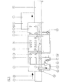
- FIG. 1 shows a side view of a commercial continuous dishwashing machine, in which - not shown - - tableware on a conveyor belt or the like is transported through the entire machine.
- the dishware passes through several separated rinsing zones, namely the pre-rinsing zone 2, the main rinsing zone 3, the Regenerier choirzone 4 and the fresh water rinse zone 5. Thereafter, a heat recovery device 6 and a drying zone 7 connects.
- the beginning of the run is denoted by 1
- the end of the run by 8 the direction of movement is denoted by 25.
- a water spraying device 9 and another Regenerierwasser sprayer 10 is provided in the main rinse zone 3
- a water spray 11 is provided in the regeneration zone 4
- a regeneration water spray 12 is provided in the fresh water rinse zone 5
- a fresh water spray 13 is provided in the regeneration zone 4.
- Die individual sprayers are each formed in duplicate, with an upper Molsprüh worn from above and a lower Partsprüh worn from below on the between them guided washings sprayed water, and some fresh water, sometimes more or less heavily polluted regeneration water or rinse water.
- Generally known devices are not shown in detail here.
- a fresh-water rinsing zone 5 with a fresh-water spraying device 13 and a regeneration rinsing zone 4 are provided, the water of which is collected in a common collecting container 19.
- This is connected via an overflow 16 to the collecting container 18 of the Hauptpülzone 11, this is connected via an overflow 15 with the collecting container 79 of the pre-rinsing zone 2, which except a first water spray 9 still an additional water spraying device 10 immediately prior to entry into the Haupt Hugheszone 3 has.
- This is supplied via a common pump 22 as the regeneration rinsing zone 4 via the collecting container 19, which contains fairly clean water.
- An important object of the invention is the pre-rinsing zone 2 with the rinse water collection container 17 and the subsequent facilities.
- the bottom of the collecting container 17 is connected via a feed line 21a and a circulation pump 21 with a centrifugal separator 20, which is already known as such and, for example, in the DE-PS 1965828 as well as the DE-OS 1703612 is described.
- the rinsing water of the collecting container 17 introduced laterally into the downwardly tapering conical centrifugal separator 20 under pressure is separated there into downwardly forced and upwardly pressed clear water. The latter is fed directly via a corresponding supply line of the water spray 9 of the pre-rinsing zone 2.
- the dirty water is forced through the line 24a upwards, namely to the top of the collecting container 17, from where it drains via an inlet or overflow 24 in an adjacent outflow 23 can.
- At the inlet 24 opposite side of the drain 23 of the overflow 14 of the collecting container 17 is arranged, which defines the maximum liquid level thereof.
- the largely purified water in the centrifugal separator 20 is used directly for pre-rinsing the items in the pre-rinsing 2, after which it can enter the next treatment zone via a second sprayer 10, which is fed by the regeneration water of the regeneration collection container 19 ,
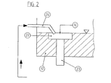
- FIG. 2 shows in cross section the collecting container 17, the overflow 14 with an antechamber 27 provided therein, the inlet 24 for the dirty water and the drain 23rd
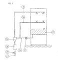
- FIG. 3 shows an embodiment of a pre-rinsing zone 2 or a simple dishwasher without a pass, where the items to be washed is always at the same place and the individual functions are performed sequentially in time.
- FIG. 4 shows in principle the same representation as FIG. 3 , Only with an additional line 9a to additional or alternative spraying 9a, which is provided behind the common circulation pump 21, but before the centrifugal separator 20 to allow the even dirtier rinse water from below to act directly on the dishes, while from above the cleaner, from the centrifugal separator Clear water emerging upwards is sprayed onto the items to be washed via the water spraying device 9.
Landscapes
- Engineering & Computer Science (AREA)
- Water Supply & Treatment (AREA)
- Washing And Drying Of Tableware (AREA)
Claims (7)
- Lave-vaisselle dans lequel la vaisselle est traitée dans une ou plusieurs zones de traitement successives (1 - 7),a) avec au moins un système de jet d'eau (9) dans au moins une zone de traitement (2),b) avec au moins un bac de récupération (17) de l'eau de rinçage dans l'au moins une zone de traitement (2) et en dessous du système de jet d'eau (9),c) qui est relié à un écoulement (23),d) avec une limitation de niveau pour l'eau de rinçage,e) avec une conduite d'amenée (21a) provenant du bac de récupération (17) et menant au système de jet d'eau (9) dans laquelle est disposée une pompe de circulation (21),f) caractérisé en ce qu'est prévu un cyclone (20) qui, par l'intermédiaire d'une conduite d'amenée et d'une pompe de circulation, est alimenté sous pression en eau de rinçage provenant du bac de récupération (17), cette eau étant séparée en eau sensiblement propre acheminée vers le haut jusque dans la zone de traitement (2) située au-dessus du bac de récupération (17) et en eau sale acheminée vers l'écoulement (23),g) l'eau propre étant acheminée directement du cyclone (20) vers le système de jet d'eau (9) qui l'utilise pour en asperger la vaisselle,h) la conduite d'amenée (21a) provenant du bac de récupération (17) et menant vers le cyclone (20) servant en même temps de conduite acheminant l'eau de rinçage provenant du bac de récupération (17) vers un autre système de jet d'eau (9a) de la même zone de rinçage (2),i) et la pompe de circulation (21) depuis le bac de récupération (17) vers le cyclone (20) servant en même temps de pompe de circulation de l'eau de rinçage acheminée directement vers le bac de récupération (17) vers l'autre système de jet d'eau (9a).
- Lave-vaisselle selon la revendication 1, caractérisé en ce que la limitation de niveau de l'eau de rinçage dans le bac de récupération (17) se fait par un trop-plein (14) à l'intérieur du bac de récupération (17).
- Lave-vaisselle selon la revendication 2, caractérisé par une chambre collectrice (28) située sur le trop-plein (14) vers laquelle est acheminée sous pression l'eau sale provenant de la sortie inférieure du cyclone (20).
- Lave-vaisselle selon l'une quelconque des revendications 1 à 3, caractérisé par sa réalisation sous forme de lave-vaisselle convoyeur avec plusieurs zones de rinçage disposées les unes derrière les autres, à savoir une première zone de rinçage préalable (2) qui contient le cyclone (20) avec le système de séparation et le système de circulation depuis le bac de récupération (17) vers le système de jet d'eau (9) ainsi que l'écoulement (23),
avec une zone de rinçage principal (3) qui contient des systèmes de jet d'eau principaux, une alimentation en produit de lavage et similaire,
avec une zone de rinçage final par circulation (4) et une dernière zone de rinçage final par eau fraîche (5) que viennent prolonger une zone de séchage (7) et de préférence une zone de récupération de la chaleur (6). - Lave-vaisselle selon l'une quelconque des revendications 1 à 4, caractérisé en ce que l'eau sale acheminée depuis le cyclone (20) jusque dans la chambre collectrice (28) est disposée en regard du trop-plein (14) du bac de récupération (17) de telle sorte qu'il se forme un contre-courant.
- Lave-vaisselle selon l'une quelconque des revendications 3-5, caractérisé en ce que la chambre collectrice (28) est vidée par l'intermédiaire d'une électrovanne ou d'une vanne similaire qui est apte à être actionnée par le biais de la commande à programme du lave-vaisselle.
- Lave-vaisselle selon l'une quelconque des revendications 1 à 6, caractérisé en ce que l'eau de régénération de la zone de rinçage final (4) recueillie dans un bac de récupération (19) asperge la vaisselle par l'intermédiaire d'une pompe de circulation (22), en plus du système de jet d'eau de rinçage final (12), faisant ainsi office d'eau de rinçage intermédiaire entre la zone de rinçage préalable et la zone de rinçage principale (3) moyennant un système de jet d'eau intermédiaire (10).
Applications Claiming Priority (2)
| Application Number | Priority Date | Filing Date | Title |
|---|---|---|---|
| DE19836739 | 1998-08-13 | ||
| DE1998136739 DE19836739A1 (de) | 1998-08-13 | 1998-08-13 | Geschirrspülmaschine |
Publications (3)
| Publication Number | Publication Date |
|---|---|
| EP0980669A2 EP0980669A2 (fr) | 2000-02-23 |
| EP0980669A3 EP0980669A3 (fr) | 2000-03-29 |
| EP0980669B1 true EP0980669B1 (fr) | 2008-06-18 |
Family
ID=7877441
Family Applications (1)
| Application Number | Title | Priority Date | Filing Date |
|---|---|---|---|
| EP19990112992 Expired - Lifetime EP0980669B1 (fr) | 1998-08-13 | 1999-07-06 | Lave-vaisselle |
Country Status (2)
| Country | Link |
|---|---|
| EP (1) | EP0980669B1 (fr) |
| DE (2) | DE19836739A1 (fr) |
Families Citing this family (15)
| Publication number | Priority date | Publication date | Assignee | Title |
|---|---|---|---|---|
| DE20017158U1 (de) * | 2000-10-06 | 2000-12-21 | Jesinghaus & Co Maschb Gmbh | Vorrichtung zum Spülen von Mehrwegtrinkgefäßen |
| AT6023U1 (de) * | 2002-04-19 | 2003-03-25 | Hagleitner Betr Shygiene Ges M | Dosiereinrichtung |
| DE10222215A1 (de) * | 2002-05-16 | 2003-12-04 | Electrolux Home Prod Corp | Verfahren zum Betreiben einer Geschirrspülmaschine |
| DE102004030003A1 (de) | 2004-06-22 | 2006-01-12 | Premark Feg L.L.C. (N.D.Ges.D. Staates Delaware), Wilmington | Spülmaschinen-Betriebsverfahren und Transportspülmaschine |
| DE102004030001A1 (de) * | 2004-06-22 | 2006-01-12 | Premark Feg L.L.C., Wilmington | Spülmaschinen-Betriebsverfahren und Transportspülmaschine |
| DE102004030015A1 (de) * | 2004-06-22 | 2006-01-12 | Premark Feg L.L.C., Wilmington | Spülmaschinen-Betriebsverfahren und Transportspülmaschine |
| DE102004045445A1 (de) | 2004-09-18 | 2006-03-23 | Premark Feg L.L.C., Wilmington | Geschirrspülanlage |
| DE102005015157A1 (de) * | 2005-04-02 | 2006-10-05 | Premark Feg L.L.C., Wilmington | Mehrtank-Transportspülmaschine und ein Betriebsverfahren hierfür |
| DE102005035764A1 (de) | 2005-07-29 | 2007-02-01 | Premark Feg L.L.C., Wilmington | Transportgeschirrspülmaschine und Betriebsverfahren hierfür |
| DE102005038433A1 (de) * | 2005-08-12 | 2007-02-15 | Premark Feg L.L.C. (N.D.Ges.D. Staates Delaware), Wilmington | Transport-Geschirrspülmaschine |
| DE102006005074A1 (de) * | 2006-02-03 | 2007-08-09 | Premark Feg L.L.C., Wilmington | Transportgeschirrspülmaschine |
| DE102006062228B4 (de) * | 2006-12-22 | 2009-02-05 | Meiko Maschinenbau Gmbh & Co. Kg | Schwemmbehälter |
| DE102008005876B3 (de) * | 2008-01-24 | 2009-04-30 | Meiko Maschinenbau Gmbh & Co.Kg | Verfahren zur Selbstreinigung einer Durchlaufspülmaschine |
| DE102008022960A1 (de) * | 2008-05-09 | 2009-11-12 | Meiko Maschinenbau Gmbh & Co. Kg | Schmutzabscheider-Einrichtung mit Niveauregelung |
| US10390675B2 (en) | 2015-06-01 | 2019-08-27 | Illinois Tool Works Inc. | Warewash machine cleaning notification and in-situ dilution process |
Family Cites Families (7)
| Publication number | Priority date | Publication date | Assignee | Title |
|---|---|---|---|---|
| AT304004B (de) * | 1969-05-08 | 1972-12-27 | Zanussi A Spa Industrie | Geschirrspülmaschine |
| DE1965828C3 (de) * | 1969-12-20 | 1973-11-22 | Karl Winterhalter Kg, 7996 Meckenbeuren | Automatische Gerschirrspülmaschine mit Fliehkraftabscheider |
| AU527001B2 (en) * | 1978-12-29 | 1983-02-10 | Hobart International Inc. | Warewasher bypass soil collector |
| FR2530942B1 (fr) * | 1982-07-29 | 1985-11-08 | Fast Lunch | Dispositif pour le lavage de plateaux |
| DE4131914C2 (de) * | 1991-09-25 | 1997-09-18 | Aeg Hausgeraete Gmbh | Siebkombination für Haushalt-Geschirrspülmaschinen |
| US5546969A (en) * | 1995-05-03 | 1996-08-20 | Blako Inc. | Dishwashing machine with integrated recycling system |
| US5770058A (en) * | 1995-09-29 | 1998-06-23 | Whirlpool Corporation | Centrifugal separator |
-
1998
- 1998-08-13 DE DE1998136739 patent/DE19836739A1/de not_active Withdrawn
-
1999
- 1999-07-06 EP EP19990112992 patent/EP0980669B1/fr not_active Expired - Lifetime
- 1999-07-06 DE DE59914788T patent/DE59914788D1/de not_active Expired - Lifetime
Also Published As
| Publication number | Publication date |
|---|---|
| EP0980669A2 (fr) | 2000-02-23 |
| DE59914788D1 (de) | 2008-07-31 |
| EP0980669A3 (fr) | 2000-03-29 |
| DE19836739A1 (de) | 2000-02-17 |
Similar Documents
| Publication | Publication Date | Title |
|---|---|---|
| EP0980669B1 (fr) | Lave-vaisselle | |
| DE19644438C2 (de) | Durchlaufgeschirrspülvorrichtung sowie Verfahren zum Reinigen von Geschirr- und/oder Tabletteilen | |
| EP1752080B1 (fr) | Lave-vaisselle du type transport comportant des moyens pour réduire la salissure du fluide de lavage | |
| DE102009048810B4 (de) | Spülmaschine mit Schmutzaustragsystem | |
| DE102005014353A1 (de) | Transportspülmaschine und Verfahren hierfür | |
| EP2252191A1 (fr) | Procédé d'auto-nettoyage d'un lave-vaisselle à avancement automatique et lave-vaisselle à avancement automatique correspondant | |
| DE102011007507A1 (de) | Transportspülmaschine sowie Verfahren zum Betreiben einer Transportspülmaschine | |
| DE2910140A1 (de) | Verfahren und vorrichtung zum automatischen waschen und spuelen von waesche | |
| EP1637059B1 (fr) | Installation de lave-vaiselle | |
| WO1994010895A1 (fr) | Lave-vaisselle | |
| DE102015214300A1 (de) | Transportspülmaschine sowie Verfahren zum Betreiben einer Transportspülmaschine | |
| EP1983087B1 (fr) | Procédé destinés au traitement humide de pièces de linge | |
| WO2012139772A1 (fr) | Machine à laver à transporteur possédant une zone de traitement spéciale | |
| DE102005015157A1 (de) | Mehrtank-Transportspülmaschine und ein Betriebsverfahren hierfür | |
| EP1042983A1 (fr) | Machine à laver vaisselle du type à tunnel | |
| DE4210577C2 (de) | Verfahren zum Spülschleudern von Wäsche in einer programmgesteuerten Waschmaschine | |
| DE102010063711A1 (de) | Spülmaschine mit automatischer Schmutzaustragung | |
| DE4100164C1 (fr) | ||
| DE4038305C1 (en) | Treating waste water from vehicle washing plant - in which water is collected from each washing zone and supplied to at least two=stage treatment plant | |
| DE69827378T2 (de) | Vorrichtung zum Filtern von Waschflüssigkeit in einem Geschirrspüler | |
| DE102008028304A1 (de) | Transportspülmaschine, insbesondere gewerbliche Korbtransportspülmaschine, und Verfahren zu deren Betrieb | |
| EP3216907A1 (fr) | Procédé de traitement par voie humide de linge | |
| DE10031038B4 (de) | Verfahren zum Abscheiden von Verunreinigungen aus einer Flüssigkeit zum Waschen von Wäsche in einer Durchlaufwaschmaschine | |
| DE102016004207A1 (de) | Verfahren zur Nassbehandlung von Wäsche | |
| DE2812666A1 (de) | Verfahren und vorrichtung zum trockenreinigen |
Legal Events
| Date | Code | Title | Description |
|---|---|---|---|
| PUAI | Public reference made under article 153(3) epc to a published international application that has entered the european phase |
Free format text: ORIGINAL CODE: 0009012 |
|
| PUAL | Search report despatched |
Free format text: ORIGINAL CODE: 0009013 |
|
| AK | Designated contracting states |
Kind code of ref document: A2 Designated state(s): DE FR GB IT |
|
| AX | Request for extension of the european patent |
Free format text: AL;LT;LV;MK;RO;SI |
|
| AK | Designated contracting states |
Kind code of ref document: A3 Designated state(s): AT BE CH CY DE DK ES FI FR GB GR IE IT LI LU MC NL PT SE |
|
| AX | Request for extension of the european patent |
Free format text: AL;LT;LV;MK;RO;SI |
|
| 17P | Request for examination filed |
Effective date: 20000527 |
|
| AKX | Designation fees paid |
Free format text: DE FR GB IT |
|
| 17Q | First examination report despatched |
Effective date: 20070323 |
|
| GRAP | Despatch of communication of intention to grant a patent |
Free format text: ORIGINAL CODE: EPIDOSNIGR1 |
|
| GRAS | Grant fee paid |
Free format text: ORIGINAL CODE: EPIDOSNIGR3 |
|
| GRAA | (expected) grant |
Free format text: ORIGINAL CODE: 0009210 |
|
| AK | Designated contracting states |
Kind code of ref document: B1 Designated state(s): DE FR GB IT |
|
| REG | Reference to a national code |
Ref country code: GB Ref legal event code: FG4D Free format text: NOT ENGLISH |
|
| REF | Corresponds to: |
Ref document number: 59914788 Country of ref document: DE Date of ref document: 20080731 Kind code of ref document: P |
|
| PLBE | No opposition filed within time limit |
Free format text: ORIGINAL CODE: 0009261 |
|
| STAA | Information on the status of an ep patent application or granted ep patent |
Free format text: STATUS: NO OPPOSITION FILED WITHIN TIME LIMIT |
|
| 26N | No opposition filed |
Effective date: 20090319 |
|
| REG | Reference to a national code |
Ref country code: DE Ref legal event code: R082 Ref document number: 59914788 Country of ref document: DE Representative=s name: BOEHMERT & BOEHMERT ANWALTSPARTNERSCHAFT MBB -, DE Ref country code: DE Ref legal event code: R082 Ref document number: 59914788 Country of ref document: DE Representative=s name: BOEHMERT & BOEHMERT, DE |
|
| REG | Reference to a national code |
Ref country code: FR Ref legal event code: PLFP Year of fee payment: 17 |
|
| PGFP | Annual fee paid to national office [announced via postgrant information from national office to epo] |
Ref country code: GB Payment date: 20150724 Year of fee payment: 17 Ref country code: DE Payment date: 20150730 Year of fee payment: 17 |
|
| PGFP | Annual fee paid to national office [announced via postgrant information from national office to epo] |
Ref country code: FR Payment date: 20150730 Year of fee payment: 17 |
|
| PGFP | Annual fee paid to national office [announced via postgrant information from national office to epo] |
Ref country code: IT Payment date: 20150728 Year of fee payment: 17 |
|
| REG | Reference to a national code |
Ref country code: DE Ref legal event code: R119 Ref document number: 59914788 Country of ref document: DE |
|
| GBPC | Gb: european patent ceased through non-payment of renewal fee |
Effective date: 20160706 |
|
| PG25 | Lapsed in a contracting state [announced via postgrant information from national office to epo] |
Ref country code: DE Free format text: LAPSE BECAUSE OF NON-PAYMENT OF DUE FEES Effective date: 20170201 Ref country code: FR Free format text: LAPSE BECAUSE OF NON-PAYMENT OF DUE FEES Effective date: 20160801 |
|
| REG | Reference to a national code |
Ref country code: FR Ref legal event code: ST Effective date: 20170331 |
|
| PG25 | Lapsed in a contracting state [announced via postgrant information from national office to epo] |
Ref country code: GB Free format text: LAPSE BECAUSE OF NON-PAYMENT OF DUE FEES Effective date: 20160706 |
|
| PG25 | Lapsed in a contracting state [announced via postgrant information from national office to epo] |
Ref country code: IT Free format text: LAPSE BECAUSE OF NON-PAYMENT OF DUE FEES Effective date: 20160706 |