EP0980577B1 - Anordnung von schaltern - Google Patents
Anordnung von schaltern Download PDFInfo
- Publication number
- EP0980577B1 EP0980577B1 EP98933440A EP98933440A EP0980577B1 EP 0980577 B1 EP0980577 B1 EP 0980577B1 EP 98933440 A EP98933440 A EP 98933440A EP 98933440 A EP98933440 A EP 98933440A EP 0980577 B1 EP0980577 B1 EP 0980577B1
- Authority
- EP
- European Patent Office
- Prior art keywords
- housing
- carrier part
- switching element
- board
- switch arrangement
- Prior art date
- Legal status (The legal status is an assumption and is not a legal conclusion. Google has not performed a legal analysis and makes no representation as to the accuracy of the status listed.)
- Expired - Lifetime
Links
- 238000007789 sealing Methods 0.000 claims abstract description 40
- 238000005406 washing Methods 0.000 claims abstract description 5
- 229920003023 plastic Polymers 0.000 claims description 11
- 239000000463 material Substances 0.000 claims description 9
- 239000004033 plastic Substances 0.000 claims description 9
- 239000004020 conductor Substances 0.000 claims description 7
- 229920002725 thermoplastic elastomer Polymers 0.000 claims description 6
- 230000007704 transition Effects 0.000 claims description 5
- LYCAIKOWRPUZTN-UHFFFAOYSA-N Ethylene glycol Chemical compound OCCO LYCAIKOWRPUZTN-UHFFFAOYSA-N 0.000 claims description 4
- 229920001400 block copolymer Polymers 0.000 claims description 4
- 239000004952 Polyamide Substances 0.000 claims description 2
- 239000004721 Polyphenylene oxide Substances 0.000 claims description 2
- WGCNASOHLSPBMP-UHFFFAOYSA-N hydroxyacetaldehyde Natural products OCC=O WGCNASOHLSPBMP-UHFFFAOYSA-N 0.000 claims description 2
- 229920000058 polyacrylate Polymers 0.000 claims description 2
- 229920002647 polyamide Polymers 0.000 claims description 2
- -1 polybutylene terephthalate Polymers 0.000 claims description 2
- 229920001707 polybutylene terephthalate Polymers 0.000 claims description 2
- 229920000570 polyether Polymers 0.000 claims description 2
- 229920001169 thermoplastic Polymers 0.000 claims description 2
- 239000000835 fiber Substances 0.000 claims 2
- 230000000694 effects Effects 0.000 claims 1
- 238000007373 indentation Methods 0.000 claims 1
- 239000013307 optical fiber Substances 0.000 claims 1
- 230000000149 penetrating effect Effects 0.000 claims 1
- 230000002093 peripheral effect Effects 0.000 claims 1
- 238000002347 injection Methods 0.000 abstract description 3
- 239000007924 injection Substances 0.000 abstract description 3
- 238000004519 manufacturing process Methods 0.000 description 6
- 239000003344 environmental pollutant Substances 0.000 description 5
- 231100000719 pollutant Toxicity 0.000 description 5
- 230000005540 biological transmission Effects 0.000 description 3
- 239000000428 dust Substances 0.000 description 3
- 238000001746 injection moulding Methods 0.000 description 3
- XLYOFNOQVPJJNP-UHFFFAOYSA-N water Substances O XLYOFNOQVPJJNP-UHFFFAOYSA-N 0.000 description 3
- 239000012528 membrane Substances 0.000 description 2
- 230000035515 penetration Effects 0.000 description 2
- 230000009467 reduction Effects 0.000 description 2
- 238000005507 spraying Methods 0.000 description 2
- ZMHWQAHZKUPENF-UHFFFAOYSA-N 1,2-dichloro-3-(4-chlorophenyl)benzene Chemical compound C1=CC(Cl)=CC=C1C1=CC=CC(Cl)=C1Cl ZMHWQAHZKUPENF-UHFFFAOYSA-N 0.000 description 1
- 230000009471 action Effects 0.000 description 1
- 230000006978 adaptation Effects 0.000 description 1
- 239000000853 adhesive Substances 0.000 description 1
- 230000001070 adhesive effect Effects 0.000 description 1
- 230000000712 assembly Effects 0.000 description 1
- 238000000429 assembly Methods 0.000 description 1
- 230000015572 biosynthetic process Effects 0.000 description 1
- 230000008859 change Effects 0.000 description 1
- 230000006735 deficit Effects 0.000 description 1
- 230000001419 dependent effect Effects 0.000 description 1
- 238000005516 engineering process Methods 0.000 description 1
- 239000002991 molded plastic Substances 0.000 description 1
- 230000002028 premature Effects 0.000 description 1
- 239000000243 solution Substances 0.000 description 1
- 239000004416 thermosoftening plastic Substances 0.000 description 1
Images

Classifications
-
- A—HUMAN NECESSITIES
- A47—FURNITURE; DOMESTIC ARTICLES OR APPLIANCES; COFFEE MILLS; SPICE MILLS; SUCTION CLEANERS IN GENERAL
- A47L—DOMESTIC WASHING OR CLEANING; SUCTION CLEANERS IN GENERAL
- A47L15/00—Washing or rinsing machines for crockery or tableware
- A47L15/42—Details
- A47L15/4293—Arrangements for programme selection, e.g. control panels; Indication of the selected programme, programme progress or other parameters of the programme, e.g. by using display panels
-
- D—TEXTILES; PAPER
- D06—TREATMENT OF TEXTILES OR THE LIKE; LAUNDERING; FLEXIBLE MATERIALS NOT OTHERWISE PROVIDED FOR
- D06F—LAUNDERING, DRYING, IRONING, PRESSING OR FOLDING TEXTILE ARTICLES
- D06F39/00—Details of washing machines not specific to a single type of machines covered by groups D06F9/00 - D06F27/00
- D06F39/12—Casings; Tubs
-
- H—ELECTRICITY
- H01—ELECTRIC ELEMENTS
- H01H—ELECTRIC SWITCHES; RELAYS; SELECTORS; EMERGENCY PROTECTIVE DEVICES
- H01H13/00—Switches having rectilinearly-movable operating part or parts adapted for pushing or pulling in one direction only, e.g. push-button switch
- H01H13/70—Switches having rectilinearly-movable operating part or parts adapted for pushing or pulling in one direction only, e.g. push-button switch having a plurality of operating members associated with different sets of contacts, e.g. keyboard
-
- H—ELECTRICITY
- H01—ELECTRIC ELEMENTS
- H01H—ELECTRIC SWITCHES; RELAYS; SELECTORS; EMERGENCY PROTECTIVE DEVICES
- H01H11/00—Apparatus or processes specially adapted for the manufacture of electric switches
- H01H11/04—Apparatus or processes specially adapted for the manufacture of electric switches of switch contacts
- H01H11/06—Fixing of contacts to carrier ; Fixing of contacts to insulating carrier
- H01H2011/065—Fixing of contacts to carrier ; Fixing of contacts to insulating carrier by plating metal or conductive rubber on insulating substrate, e.g. Molded Interconnect Devices [MID]
-
- H—ELECTRICITY
- H01—ELECTRIC ELEMENTS
- H01H—ELECTRIC SWITCHES; RELAYS; SELECTORS; EMERGENCY PROTECTIVE DEVICES
- H01H2215/00—Tactile feedback
- H01H2215/004—Collapsible dome or bubble
-
- H—ELECTRICITY
- H01—ELECTRIC ELEMENTS
- H01H—ELECTRIC SWITCHES; RELAYS; SELECTORS; EMERGENCY PROTECTIVE DEVICES
- H01H2217/00—Facilitation of operation; Human engineering
- H01H2217/022—Part of keyboard not operable
-
- H—ELECTRICITY
- H01—ELECTRIC ELEMENTS
- H01H—ELECTRIC SWITCHES; RELAYS; SELECTORS; EMERGENCY PROTECTIVE DEVICES
- H01H2219/00—Legends
- H01H2219/054—Optical elements
- H01H2219/062—Light conductor
-
- H—ELECTRICITY
- H01—ELECTRIC ELEMENTS
- H01H—ELECTRIC SWITCHES; RELAYS; SELECTORS; EMERGENCY PROTECTIVE DEVICES
- H01H2219/00—Legends
- H01H2219/054—Optical elements
- H01H2219/064—Optical isolation of switch sites
-
- H—ELECTRICITY
- H01—ELECTRIC ELEMENTS
- H01H—ELECTRIC SWITCHES; RELAYS; SELECTORS; EMERGENCY PROTECTIVE DEVICES
- H01H2221/00—Actuators
- H01H2221/036—Return force
- H01H2221/044—Elastic part on actuator or casing
-
- H—ELECTRICITY
- H01—ELECTRIC ELEMENTS
- H01H—ELECTRIC SWITCHES; RELAYS; SELECTORS; EMERGENCY PROTECTIVE DEVICES
- H01H2223/00—Casings
- H01H2223/002—Casings sealed
-
- H—ELECTRICITY
- H01—ELECTRIC ELEMENTS
- H01H—ELECTRIC SWITCHES; RELAYS; SELECTORS; EMERGENCY PROTECTIVE DEVICES
- H01H2229/00—Manufacturing
- H01H2229/022—Modular assembly
-
- H—ELECTRICITY
- H01—ELECTRIC ELEMENTS
- H01H—ELECTRIC SWITCHES; RELAYS; SELECTORS; EMERGENCY PROTECTIVE DEVICES
- H01H2229/00—Manufacturing
- H01H2229/042—Snap coupling; Snap mounting
-
- H—ELECTRICITY
- H01—ELECTRIC ELEMENTS
- H01H—ELECTRIC SWITCHES; RELAYS; SELECTORS; EMERGENCY PROTECTIVE DEVICES
- H01H2229/00—Manufacturing
- H01H2229/044—Injection moulding
- H01H2229/046—Multi-colour or double shot injection moulding
-
- H—ELECTRICITY
- H01—ELECTRIC ELEMENTS
- H01H—ELECTRIC SWITCHES; RELAYS; SELECTORS; EMERGENCY PROTECTIVE DEVICES
- H01H2231/00—Applications
- H01H2231/012—Household appliance
Definitions
- the invention relates to a switch arrangement with at least a switching element and an actuator according to Preamble of claim 1.
- Such switch arrangements are used to select functions of electrical equipment by the user. It can these electrical devices around home appliances like washing machines, Dryers, dishwashers or the like, act.
- Such a switch arrangement is known from DE 195 03 702 A1 known a housing.
- Switching elements are arranged for actuating action on the switching elements.
- actuators are actuators on the housing arranged.
- the inner case has a membrane shape trained wall on that between the switching elements and the Actuators is arranged. The actuators work over the membrane-shaped, in the direction of movement of the Actuators elastic wall on the switching elements.
- the membrane-shaped wall on the inner housing thus acts as elastic sealing element between the actuator and the Switching element that prevents the ingress of pollutants, such as water, Dust or the like, in the interior of the switch assembly prevented.
- pollutants such as water, Dust or the like
- the manufacture of the inner case very complex.
- the switching elements must already at Manufacturing process for the inner housing introduced into this become. A subsequent change in the number of Switching elements are no longer possible. It has therefore proven to be disadvantageously pointed out that the known switch arrangement little flexible and not simply different Device configurations is customizable.
- the invention has for its object a Form switch arrangement such that a flexible Adaptation to different device configurations in is possible in a simple way and is nevertheless a harmful one Avoidance of pollutants on the switching elements avoided is.
- one serving as a switching element Snap disc in the manner of a two-component part directly on the receptacle for the actuator in the carrier part to mold.
- the switching element itself acts as Sealing element, so that both the switching function and a Sealing can be realized using a single element.
- An advantageous further development also consists in a all-round seal for lateral sealing of the Switching element-receiving space in the manner of a two-component part molded onto the carrier part. This can be done in same tool in the injection molding operation Snap disks happen when used as a material for the sealing lip the same material used for the snap disc. Despite the reduction in the number of parts, this is an excellent one Sealing guaranteed.
- Light guide integrated in the carrier part. It is preferred then the one used to hold the actuators Carrier part made of optically transparent plastic. So that the carrier part is simultaneously for the transmission of Light for functional lighting or the like of the actuators use. Finally, it is also appropriate that the carrier part to provide the facing side of the housing with conductor tracks, for example as a MID (Molded Interconnected Device) part.
- the Conductor tracks serve as fixed contacts for the snap disks as well as for establishing the required electrical connections for the switching elements.
- a switch arrangement with the mentioned further education Refinements essentially consist of two parts. At the The first part is the case with the Conductor tracks that serve as the main body for the switch arrangement serves.
- the second part serves as a carrier part for the Actuators and is included as a two-component part integrated snap disks, seals and light guides Mistake.
- the second part is then like a lid on the first part by locking connections, snap hooks or the like attached. Then this arrangement can still be used with a covering panel are provided, through which the Protruding actuators. It is immediate can be seen that due to the simple structure and the small number of parts a simplified assembly of the Switch arrangement results.
- the advantages achieved with the invention are in particular in that the switching elements of the switch assembly receiving space at all openings and junctions easily sealed against ingress of water, dust or the like is, so that the switching elements from damaging influences are protected. This eliminates the risk of premature Failure of the switch assembly, even under difficult ones Operating conditions improved significantly.
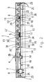
- Fig. 1 is a switch arrangement 1 for an electrical Household appliance, which is, for example, a washing machine or a dishwasher, shown in plan view.
- the switch assembly 1 has a housing 2 which on the Top is provided with an aperture 3. Through the aperture 3 protrude on the housing 2 arranged actuators 4, 5, 6, 7th manually accessible through, with the help of the user Select various functions of the electrical household appliance can.
- a display 8 in the panel 2 for example an LED or LCD display in which the user Operating states of the household appliance can be visualized.
- Switch 9 is a power switch for switching the household appliance on and off.
- Switch 10 is a rotary switch, with whose help the respective program of the household appliance can be set is.
- the actuators 5, 6 are finally used for selection various functions of the household appliance.
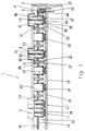
- the actuator 6 consists of a button 12 and a plunger 13 and acts actuating the associated switching element 11.
- the Actuator 5 consists of one in two directions movable rocker 12 'on two switching elements 11, 11' acts. For example, in a washing machine the actuator 5 an increase or decrease in Temperature and by means of the actuator 6 the execution an additional prewash cycle can be selected.
- the housing 2 has a carrier part 14, which is preferably is arranged in the housing interior 16 as a type of cover.
- the carrier part 14 can also be a component of the housing 2 or also in one piece with the housing 2 be trained.
- the carrier part 14 is approximately pot-like configured receptacles 15 for the actuators 5, 6.
- the plunger 13 in the receptacle 15 in its Movable in the longitudinal direction.
- the receptacle 15 in the carrier part 14 has a on the side facing the housing interior 16 Opening 17, which is assigned to the respective switching element 11, 11 ' is.
- the carrier part 14 consists of a hard plastic. It is preferably a thermoplastic, such as polyacrylate, polyamide o. Like. So that the support member 14 and / or the housing 2 by means Injection molding can be made.
- the sealing element 18 is in the manner of a two-component part on the carrier part 14 molded, with a material connection between the Edge at the opening 17 and the sealing element 18. It offers itself as a material for the sealing element 18 an elastic plastic, like a thermoplastic Elastomer to choose that with the plastic for the support part 14 a good adhesive connection is established. As particularly suitable has a block copolymer as a thermoplastic elastomer Polybutylene terephthalate and polyether glycol proved.
- the housing 2 is one containing the electrical connections Circuit board 19 arranged for receiving the switching elements 11, 11 '. It lends itself to the power switch 9 and the Arrange rotary switch 11 on the board 19.
- the board 19 can be a conventional circuit board.
- the board 19 is part of the Housing 2 formed in the manner of a MID part.
- MID Molded Interconnected Device
- the board 19 is part of the Housing 2 formed in the manner of a MID part.
- a MID (Molded Interconnected Device) part is a injection molded plastic part, located on the conductor tracks are so that the MID part like a circuit board for recording serves electrical and / or electronic components.
- the board 19 is in one piece with the Housing 2 made in injection molding technology as Housing end part on the switching element 11, 11 ' assigned underside of the housing 2. Opposite is, as already stated, on the Actuator 5, 6 associated top of the housing 2 the Aperture 3.
- the electrical connections for the board 19 containing side of the housing end part is the Interior 16 facing. That fixed on the board 19
- Switching element 11, 11 ' is made of plastic, such as one thermoplastic elastomer, existing snap disc, Switch cap or contact element formed.
- Such Snap disc which are provided with a bridging contact is known for example from DE-OS 41 12 754.
- On the board 19 are used as fixed contacts, with the Conductor-related contact areas with which the bridging contact in the snap disk for making contact cooperates when the plunger 13 on the sealing element 18 the snap disc acts. Of course you can Conductor tracks themselves serve as fixed contacts.
- the electronic circuit 20 is on a board 19 serving as the housing end part PCB 22 fastened by means of snap hooks 21.
- the electronic circuit 20 can additionally Switching signals into corresponding electrical signals, such as Convert bus signals or the like.
- About one in the electronic Circuit 20 arranged interface electronics then takes place a transmission of the electrical signals between the electronic circuit 20 and other components, such as one Microcomputer or the like, in the household appliance.
- the carrier part 14 is by means of snap hooks 23 or the like Locking elements in the housing 2, specifically there on the board 19 attached.
- the switching elements 11, 11 ' are in the Housing interior 16 in the space 24 between the carrier part 14 and the circuit board 19. This space 24 is located at the openings 17 sealed by the sealing elements 18.
- a substantially all-round elastic sealing lip 25 which seals the space 24 laterally.
- the sealing lip 25 also consists of a thermoplastic Elastomer, such as the above block copolymer, and is again in the manner of a two-component part on the carrier part 14 molded.
- the sealing lip 25 lies with the free surface on the board 19. If necessary, a on the board 19 raised edge 40, as can be seen in Fig.
- FIG. 3 Another embodiment of the invention is shown in FIG. 3 shown.
- the Snap disk 34 consists of a on the board 19th arranged base part 35 and one over a lateral surface 37 with the base part 35 connected lid 36, which in the opening 17 protrudes.
- the actuator 5, 6 acts via the plunger 13 on the lid 36 for actuating the snap disk 34.
- a spring-like, elastic connecting element 38 is on the one hand with the edge of the base part 35 and on the other hand with a fastening element 39 preferably in one piece connected. Distance tolerances to the board 19 are from Compensated connecting element 38.
- the fastening element 39 is at the edge of the opening 17 molded on the side facing the housing interior 16.
- the Snap disc 34 together with the fastener 39 and the Connection element 38 simultaneously the injection of Sealing lip 25 take place.
- the used when spraying Flow channels 41 in the carrier part 14 for the plastic Manufacture of the snap disk 34 and the sealing lip 25 are in Fig. 3 in section on the side facing the panel 3 see.
- the including the connector 38 and the Fastening element 39 made of a thermoplastic elastomer, such as the block copolymer given above Snap disc 34 then acts simultaneously as a sealing element, so that the separate sealing element 18 can be dispensed with.
- recordings not occupied by actuators can be made 15 'also with molded-on snap disks 34 for simple production of variants.
- the carrier part 14 is preferably a multifunctional part formed, on the one hand, the mounting of the actuators 5, 6 effected according to the above description and on the other hand Transmission of light from lighting elements 27 in Housing interior 16 is generated to the outside of the housing 2nd serves. As can be seen in Fig. 1, this can be done at the Outside of the housing 2, for example on the panel 3, Window 28 may be arranged.
- the lighting element lights up 27 can, for example, actuate the corresponding one Signal actuator 5, 6.
- Carrier part 14 from a for light in the visible range largely transparent plastic.
- the carrier part 14 has then a first region 30 which is substantially parallel to the Board 19 runs, and a second region 31, the is approximately perpendicular to the first region 30.
- the first Area 30 contains the recordings 15, 15 'for the Actuators 5, 6 while the second area 31 as actual light guide rod 29 is used. This turns the light from the lighting element 27 via the carrier part 14 essentially in Directed to the outside of the housing 2.
- the transition 32 between the first is now Area 30 and the second area 31 formed such that a transition of the light guided in the second region 31 into the first area 30 is substantially prevented.
- the transition 32 are available for example, constrictions 33, depressions or the like. This ensures that the light in the light guide rod 29 for Aperture 3 is performed and not or only in a small amount Dimension on the side on the optically transparent Carrier part 14 can spread.
- the invention is not limited to that described and illustrated Embodiments limited. Rather, it includes everyone professional training within the scope of the claims. So the invention can also Switch arrangements for machine tools, motor vehicles, Keyboards or the like can be used.
Landscapes
- Engineering & Computer Science (AREA)
- Textile Engineering (AREA)
- Switch Cases, Indication, And Locking (AREA)
- Push-Button Switches (AREA)
Abstract
Description
- Fig. 1
- eine Draufsicht auf eine Schalteranordnung,
- Fig. 2
- einen Schnitt entlang der Linie 2-2 in Fig. 1 und
- Fig. 3
- einen Schnitt wie in Fig. 2 entsprechend einer weiteren Ausführungsform.
- 1:
- Schalteranordnung
- 2:
- Gehäuse
- 3:
- Blende
- 4:
- Betätigungsorgan (für Drehschalter)
- 5, 6:
- Betätigungsorgan (Taste, Wippe)
- 7:
- Betätigungsorgan (für Netzschalter)
- 8:
- Anzeige
- 9:
- Netzschalter
- 10:
- Drehschalter
- 11,11':
- Schaltelement
- 12:
- Taste
- 12':
- Wippe
- 13:
- Stößel
- 14:
- Trägerteil
- 15:
- Aufnahme
- 15':
- Aufnahme (unbelegt)
- 16:
- Gehäuseinneres
- 17:
- Öffnung
- 18:
- Dichtelement
- 19:
- Platine
- 20:
- elektronische Schaltung
- 21:
- Schnapphaken (für Leiterplatte)
- 22:
- Leiterplatte
- 23:
- Schnapphaken (für Trägerteil)
- 24:
- Raum (zur Aufnahme der Schaltelemente)
- 25:
- Dichtlippe
- 26:
- Dichtung
- 27:
- Leuchtelement
- 28:
- Fenster
- 29:
- Lichtleitstab
- 30:
- erster Bereich (von Trägerteil)
- 31:
- zweiter Bereich (von Trägerteil)
- 32:
- Übergang (zwischen ersten und zweiten Bereich)
- 33:
- Einschnürung
- 34:
- angespritzte Schnappscheibe
- 35:
- Basisteil
- 36:
- Deckel
- 37:
- Mantelfläche
- 38:
- Verbindungselement
- 39:
- Befestigungselement
- 40:
- erhöhter Rand (an Platine)
- 41:
- Fließkanal (im Trägerteil)
Claims (11)
- Schalteranordnung, insbesondere für Hausgeräte, wie Waschmaschinen, Trockner, Geschirrspülmaschinen o. dgl., mit einem Gehäuse (2), mit wenigstens einem im Gehäuseinneren (16) befindlichen Schaltelement (11, 11'), mit wenigstens einem am Gehäuse (2) angeordneten Betätigungsorgan (5, 6) zur betätigenden Einwirkung auf das Schaltelement (11, 11'), und mit einem das Gehäuseinnere (16) abdichtenden, zwischen dem Schaltelement (11, 11') und dem Betätigungsorgan (5, 6) angeordneten, in Bewegungsrichtung des Betätigungsorgans (5, 6) elastischen Dichtelement (18), wobei das Betätigungsorgan (5, 6) über das elastische Dichtelement (18) auf das Schaltelement (11, 11') einwirkt, dadurch gekennzeichnet, daß das Gehäuse (2) ein, insbesondere im Gehäuseinneren (16) angeordnetes, Trägerteil (14) besitzt, das eine Aufnahme (15, 15') für das Betätigungsorgan (5, 6) aufweist, daß die Aufnahme (15, 15') im Trägerteil (14) an der dem Gehäuseinneren (16) zugewandten Seite eine Öffnung (17) besitzt, die dem Schaltelement (11, 11') zugeordnet ist, daß das Dichtelement (18) an der Öffnung (17) im Trägerteil (14) angebracht ist, und daß das Dichtelement (18) in der Art eines Zwei-Komponenten-Teils am Trägerteil (14) angespritzt ist.
- Schalteranordnung nach Anspruch 1, dadurch gekennzeichnet, daß das Schaltelement (11, 11') als eine aus Kunststoff bestehende Schnappscheibe ausgebildet ist, wobei vorzugsweise das Schaltelement (11, 11') auf einer im Gehäuse (2) befindlichen, elektrische Verbindungen enthaltenden Platine (19) angeordnet ist, daß insbesondere die als Schaltelement (11, 11') dienende Schnappscheibe mit einem Überbrückungskontakt versehen ist und mit Festkontakten zusammenwirkt, wobei vorzugsweise die Festkontakte auf der Platine (19), insbesondere in der Art von Leiterbahnen, angeordnet sind.
- Schalteranordnung nach Anspruch 1 oder 2, dadurch gekennzeichnet, daß die als Schaltelement (11, 11') dienende Schnappscheibe (34) in der Art eines Zwei-Komponenten-Teils direkt an der Öffnung (17) der Aufnahme (15, 15') an der dem Gehäuseinneren (16) zugewandten Seite der bevorzugterweise topf artig ausgestalteten Aufnahme (15, 15'), angespritzt ist, derart daß die Schnappscheibe (34) gleichzeitig als Dichtelement wirkt.
- Schalteranordnung nach Anspruch 1, 2 oder 3, dadurch gekennzeichnet, daß die Aufnahme (15, 15') nach Bedarf mit weiteren Betätigungsorganen (5, 6) bestückbar ist, und daß die Öffnung (17) einer unbestückten Aufnahme (15') mit einem in der Art eines Zwei-Komponenten-Teils angespritzen Dichtelement (18) und/oder mit einer in der Art eines Zwei-Komponenten-Teils direkt angespritzten Schnappscheibe (34) versehen ist.
- Schalteranordnung nach einem der Ansprüche 1 bis 4, dadurch gekennzeichnet, daß das Trägerteil (14) mittels Schnapphaken (23) o. dgl. im Gehäuse (2), insbesondere auf der Platine (19) befestigt ist, und daß sich vorzugsweise am Trägerteil (14) eine im wesentlichen ringsumiaufende elastische Dichtlippe (25) befindet, die insbesondere in Art eines Zwei-Komponenten-Teils am Trägerteil (14) angespritzt ist, wobei die Dichtlippe (25) den das Schaltelement (11, 11') enthaltenden Raum (24) zwischen dem Trägerteil (14) und der Platine (19) im Gehäuseinneren (16) seitlich abdichtet.
- Schalteranordnung nach einem der Ansprüche 1 bis 5, dadurch gekennzeichnet, daß das Dichtelement (18) und/oder die Dichtlippe (25) und/oder die Schnappscheibe (34) aus einem elastischen Kunststoff, insbesondere aus einem thermoplastischen Elastomer, wie einem Blockcopolymer aus Polybutylen-Terephtalat und Polyetherglykol, bestehen, und daß vorzugsweise das Trägerteil (14) und/oder das Gehäuse (2) aus einem harten Kunststoff, insbesondere einem thermoplastischen Kunststoff, wie Polyacrylat, Polyamid o. dgl., bestehen.
- Schalteranordnung nach einem der Ansprüche 1 bis 6, dadurch gekennzeichnet, daß das Gehäuse (2) an der dem Schaltelement (11, 11') zugeordneten Unterseite mit einem Gehäuseabschlußteil und an der dem Betätigungsorgan (5, 6) zugeordneten Oberseite mit einer Blende (3) versehen ist, wobei das Betätigungsorgan (5, 6) für dessen manuellen Zugänglichkeit durch die Blende (3) hindurchragt, und daß vorzugsweise die dem Gehäuseinneren (16) zugewandte Seite des Gehäuseabschlußteils als Platine (19) in der Art eines MID(Moulded Interconnected Device)-Teils ausgebildet ist.
- Schalteranordnung nach einem der Ansprüche 1 bis 7, dadurch gekennzeichnet, daß am oder/und im Gehäuse (2) eine elektronische Schaltung (20), die zur Auswertung der von dem Schaltelement (11, 11') erzeugten Schaltsignale o. dgl. dient, insbesondere auf einer am Gehäuseabschlußteil befestigten Leiterplatte (22) befindlich ist, wobei gegebenenfalls auf der Leiterplatte (22) eine Schnittstellenelektronik zur Übertragung von elektrischen Signalen angeordnet ist.
- Schalteranordnung nach einem der Ansprüche 1 bis 8, dadurch gekennzeichnet, daß wenigstens ein Leuchtelement (27) im Gehäuse (2), insbesondere auf der Platine (19) angeordnet ist, und daß vorzugsweise ein dem Leuchtelement (27) zugeordneter Lichtleitstab (29) im Trägerteil (14) angeordnet ist, derart daß das Licht von dem Leuchtelement (27) im wesentlichen in Richtung zur Außenseite des Gehäuses (2), beispielsweise zu einem in der Blende (3) befindlichen Fenster (28), geführt ist.
- Schalteranordnung nach Anspruch 9, dadurch gekennzeichnet, daß das Trägerteil (14) aus einem für Licht im sichtbaren Bereich weitgehend transparenten Kunststoff besteht, so daß Licht von dem Leuchtelement (27) über das Trägerteil (14) zur Außenseite des Gehäuses (2) geleitet wird, und daß der Lichtleitstab (29) im Trägerteil (14), insbesondere einstückig, integriert ist.
- Schalteranordnung nach Anspruch 9 oder 10, dadurch gekennzeichnet, daß das Trägerteil (14) einen ersten Bereich (30), der im wesentlichen parallel zur Platine (19) angeordnet ist, sowie einen zweiten Bereich (31) besitzt, der ungefähr senkrecht zum ersten Bereich (30) steht, daß der erste Bereich (30) die Aufnahme (15, 15') für das Betätigungsorgan (5, 6) enthält, und daß der zweite Bereich (31) als Lichtleitstab (29) dient, wobei insbesondere der Übergang (32) zwischen dem ersten und dem zweiten Bereich (30, 31) derart ausgebildet ist, beispielsweise durch Einschnürungen (33), Vertiefungen o. dgl., daß der Übertritt des im zweiten Bereich (31) geführten Lichtes in den ersten Bereich (30) im wesentlichen verhindert ist.
Applications Claiming Priority (3)
| Application Number | Priority Date | Filing Date | Title |
|---|---|---|---|
| DE19719245 | 1997-05-07 | ||
| DE19719245 | 1997-05-07 | ||
| PCT/DE1998/001235 WO1998050930A1 (de) | 1997-05-07 | 1998-05-05 | Anordnung von schaltern |
Publications (2)
| Publication Number | Publication Date |
|---|---|
| EP0980577A1 EP0980577A1 (de) | 2000-02-23 |
| EP0980577B1 true EP0980577B1 (de) | 2002-03-06 |
Family
ID=7828854
Family Applications (1)
| Application Number | Title | Priority Date | Filing Date |
|---|---|---|---|
| EP98933440A Expired - Lifetime EP0980577B1 (de) | 1997-05-07 | 1998-05-05 | Anordnung von schaltern |
Country Status (4)
| Country | Link |
|---|---|
| US (1) | US6204459B1 (de) |
| EP (1) | EP0980577B1 (de) |
| DE (2) | DE19817369A1 (de) |
| WO (1) | WO1998050930A1 (de) |
Families Citing this family (21)
| Publication number | Priority date | Publication date | Assignee | Title |
|---|---|---|---|---|
| DE20013019U1 (de) * | 2000-07-27 | 2001-12-20 | Liebherr Hausgeraete | Elektronik-Bedieneinheit |
| JP3437958B2 (ja) * | 2001-01-23 | 2003-08-18 | 株式会社エルコム | キーボード装置およびその製造方法 |
| AU2002213735A1 (en) * | 2001-11-21 | 2003-06-10 | Phonak Ag | Switch cover |
| US7201175B2 (en) * | 2002-05-03 | 2007-04-10 | Whirlpool Corporation | User interface for an in-sink dishwasher |
| DE10259762A1 (de) * | 2002-12-19 | 2004-07-01 | BSH Bosch und Siemens Hausgeräte GmbH | Haushaltgerät, insbesondere Einbau-Haushaltgerät |
| PL1523022T3 (pl) | 2003-09-17 | 2012-04-30 | Pas Deutschland Gmbh | Układ przycisków do panelu obsługi |
| DE20319730U1 (de) * | 2003-12-19 | 2004-04-01 | Electrolux Home Products Corporation N.V. | Zentrierrahmen |
| GB2409576B (en) * | 2003-12-24 | 2006-01-18 | Dale Mcphee Purcocks | Keyboards |
| US7973255B2 (en) * | 2007-01-15 | 2011-07-05 | Purcocks Dale Mcphee | Keyboards |
| JP5045755B2 (ja) * | 2007-08-30 | 2012-10-10 | 富士通株式会社 | キー操作部の照光構造、電子装置、携帯装置、及びキー操作部の照光方法 |
| DE102007049571A1 (de) * | 2007-10-16 | 2009-04-23 | BSH Bosch und Siemens Hausgeräte GmbH | Hausgerätbedienvorrichtung |
| DE102008015111B3 (de) * | 2008-01-31 | 2009-06-10 | Preh Gmbh | Flüssigkeitsgeschütztes Bedienelement |
| US8178802B2 (en) * | 2008-07-31 | 2012-05-15 | Electrolux Home Products, Inc. | Unitized appliance control panel assembly and components of the assembly |
| EP2166553A1 (de) * | 2008-09-17 | 2010-03-24 | Delphi Technologies, Inc. | Elektrischer Schalter |
| DE102009036212B3 (de) * | 2009-08-05 | 2011-02-03 | Trw Automotive Electronics & Components Gmbh | Tastschaltergruppe und deren Verwendung als Bedienfeld in Kraftfahrzeugen |
| DE102009051617B3 (de) * | 2009-11-02 | 2011-04-28 | Pas Deutschland Gmbh | Taste für eine Bedienanordnung, sowie Bedienanordnung und Haushaltsgerät |
| US8530742B2 (en) * | 2010-11-17 | 2013-09-10 | Bsh Home Appliances Corporation | Household appliance including two-piece fascia panel and method of manufacturing the two-piece fascia panel |
| ES2441381T3 (es) * | 2011-12-20 | 2014-02-04 | Miele & Cie. Kg | Equipo de panel para un aparato doméstico |
| WO2015049193A1 (en) * | 2013-10-01 | 2015-04-09 | Arcelik Anonim Sirketi | A household appliance comprising a display holder |
| WO2017174146A1 (en) * | 2016-04-08 | 2017-10-12 | Arcelik Anonim Sirketi | Household appliance with an improved control panel assembly |
| US11302496B2 (en) | 2020-03-23 | 2022-04-12 | Whirlpool Corporation | Drainage assembly |
Family Cites Families (22)
| Publication number | Priority date | Publication date | Assignee | Title |
|---|---|---|---|---|
| DE2907270C2 (de) | 1979-02-24 | 1987-05-14 | Licentia Patent-Verwaltungs-Gmbh, 6000 Frankfurt | Haushaltgerät mit einem schrankförmigen Gehäuse |
| DE3111409A1 (de) * | 1981-03-24 | 1982-10-07 | Kaiser Fototechnik Gmbh & Co Kg, 6967 Buchen | Lichtleitplatte fuer die bedienungsfeldbeleuchtung |
| FR2511941B1 (fr) * | 1981-09-01 | 1988-02-05 | Telemecanique Electrique | Clavier modulaire, etanche, a effet tactile |
| DE8334679U1 (de) * | 1983-12-02 | 1984-03-01 | Siemens AG, 1000 Berlin und 8000 München | Taste |
| DE8410365U1 (de) * | 1984-04-03 | 1984-06-20 | Nixdorf Computer Ag, 4790 Paderborn | Bedienungsfeld für elektrische und elektronische Geräte |
| DE8602882U1 (de) | 1986-02-05 | 1986-04-03 | Preh, Elektrofeinmechanische Werke Jakob Preh Nachf. Gmbh & Co, 8740 Bad Neustadt | Elektrisches Handschaltgerät |
| US4772769A (en) * | 1987-02-06 | 1988-09-20 | Burr-Brown Corporation | Apparatus for selective backlighting of keys of a keyboard |
| GB8719369D0 (en) * | 1987-08-15 | 1987-09-23 | Harboro Rubber Co Ltd | Manufacture of contact pad arrays |
| DE8905799U1 (de) | 1989-05-09 | 1989-06-29 | Bosch-Siemens Hausgeräte GmbH, 8000 München | Schalterblende für ein elektrisches Haushaltgerät, insb. Geschirrspül-, Waschmaschine, Wäschetrockner, Herd o.dgl. |
| DE9011110U1 (de) * | 1990-07-27 | 1990-10-04 | Dr. Eugen Sasse GmbH, 8540 Schwabach | Tastatur, insbesondere für ein Computer-Terminal |
| DE9201985U1 (de) | 1992-02-15 | 1992-04-23 | Fa. Martin Bock, 8439 Postbauer-Heng | Befestigungsvorrichtung zur gegenseitigen Fixierung zweier Formteile |
| DE4139554A1 (de) | 1991-10-14 | 1993-04-15 | Fela Mikrotechnik Ag | Elektrischer tastschalter |
| DE4212562A1 (de) | 1992-04-15 | 1993-10-21 | Buch Elektronik Gmbh | Folientastatur |
| DE4227468C2 (de) | 1992-08-20 | 2002-01-17 | Teves Gmbh Alfred | Elektrische Schaltereinheit, insbesondere zur Steuerung von Klimaanlagen in Kraftfahrzeugen |
| US5464955A (en) | 1993-04-15 | 1995-11-07 | Emerson Electric Co. | Backlit appliance control console |
| US5704467A (en) * | 1993-04-20 | 1998-01-06 | Keymat Technology Limited | Keypads |
| US5453586A (en) | 1993-12-27 | 1995-09-26 | General Electric Company | Appliance control panel assembly |
| DE4400772C2 (de) | 1994-01-13 | 1995-12-21 | Baer Elektrowerke Gmbh & Co Kg | Elektrisches Schaltgerät |
| DE19503702B4 (de) | 1995-02-04 | 2005-10-27 | Nicolay Verwaltungs-Gmbh | Flüssigkeits- und gasdicht gekapselter Schalter, insbesondere für elektrochirurgische Instrumente |
| US5734136A (en) * | 1996-06-12 | 1998-03-31 | Qualcomm Incorporated | Keypad assembly with moisture-excluding seal |
| JPH10188094A (ja) * | 1996-12-24 | 1998-07-21 | Kouha:Kk | 自動販売機等の押ボタン |
| TW358571U (en) * | 1997-10-24 | 1999-05-11 | Acer Peripherals Inc | Water proofing keyboard |
-
1998
- 1998-04-18 DE DE19817369A patent/DE19817369A1/de not_active Withdrawn
- 1998-05-05 DE DE59803282T patent/DE59803282D1/de not_active Expired - Lifetime
- 1998-05-05 EP EP98933440A patent/EP0980577B1/de not_active Expired - Lifetime
- 1998-05-05 WO PCT/DE1998/001235 patent/WO1998050930A1/de not_active Ceased
- 1998-05-05 US US09/380,158 patent/US6204459B1/en not_active Expired - Fee Related
Also Published As
| Publication number | Publication date |
|---|---|
| WO1998050930A1 (de) | 1998-11-12 |
| DE19817369A1 (de) | 1998-11-12 |
| DE59803282D1 (de) | 2002-04-11 |
| EP0980577A1 (de) | 2000-02-23 |
| US6204459B1 (en) | 2001-03-20 |
Similar Documents
| Publication | Publication Date | Title |
|---|---|---|
| DE19817369A1 (de) | Anordnung von Schaltern | |
| EP1075578B1 (de) | Gehäuseteil mit einem betätigungsorgan | |
| DE4009279C2 (de) | ||
| DE19755497C1 (de) | Steuergerätegehäuse aus Kunststoff für ein Kraftfahrzeug | |
| EP0937305B1 (de) | Schaltersystem in mid-technik | |
| EP1656685A1 (de) | Elektronisches bauelement, insbesondere elektrischer schalter | |
| DE3019886A1 (de) | Fluessigkeits- und gasdichter schiebeschalter | |
| DE112004000492B4 (de) | Abdeckung für einen Tastenschalter | |
| DE19548866A1 (de) | Antriebsvorrichtung | |
| EP1662207B1 (de) | Bedienvorrichtung für ein elektrisches Haushaltsgerät | |
| EP1176619A2 (de) | Elektronik-Bedieneinheit | |
| EP1284333B1 (de) | Elektrische Bauelementanordnung | |
| DE4426350A1 (de) | Schaltersystem mit einem räumlich spritzgegossenen Schaltungsträger | |
| DE10158629B4 (de) | Schalter | |
| DE20317635U1 (de) | Schalt- und Beleuchtungsmodul zum Einbau in ein Kraftfahrzeug sowie Heck- oder Kofferraumklappe an einem Kraftfahrzeug | |
| EP2302655B1 (de) | Elektrischer Schalter | |
| DE69909158T2 (de) | Bedienblendeneinheit für ein Haushaltsgerät | |
| DE19708210C2 (de) | Regler, insbesondere Temperaturregler wie Raumtemperaturregler | |
| DE3827090A1 (de) | Schalterleiste | |
| DE69308401T2 (de) | Bedienungstafel mit Berührungstasten für die Regelung einer Klimatisiereinrichtung eines Fahrzeuginnenraums | |
| DE102013003072B4 (de) | Bedienvorrichtung, insbesondere für ein elektronisches Haushaltsgerät | |
| DE10131218C1 (de) | Hinterleuchteter Tastschalter | |
| DE202007005439U1 (de) | Schaltelement | |
| EP1525597B1 (de) | Beleuchtbares werkstück | |
| DE3633701C2 (de) |
Legal Events
| Date | Code | Title | Description |
|---|---|---|---|
| PUAI | Public reference made under article 153(3) epc to a published international application that has entered the european phase |
Free format text: ORIGINAL CODE: 0009012 |
|
| 17P | Request for examination filed |
Effective date: 19990619 |
|
| AK | Designated contracting states |
Kind code of ref document: A1 Designated state(s): DE FR IT NL SE |
|
| GRAG | Despatch of communication of intention to grant |
Free format text: ORIGINAL CODE: EPIDOS AGRA |
|
| 17Q | First examination report despatched |
Effective date: 20010502 |
|
| GRAG | Despatch of communication of intention to grant |
Free format text: ORIGINAL CODE: EPIDOS AGRA |
|
| GRAH | Despatch of communication of intention to grant a patent |
Free format text: ORIGINAL CODE: EPIDOS IGRA |
|
| GRAH | Despatch of communication of intention to grant a patent |
Free format text: ORIGINAL CODE: EPIDOS IGRA |
|
| GRAA | (expected) grant |
Free format text: ORIGINAL CODE: 0009210 |
|
| AK | Designated contracting states |
Kind code of ref document: B1 Designated state(s): DE FR IT NL SE |
|
| PG25 | Lapsed in a contracting state [announced via postgrant information from national office to epo] |
Ref country code: NL Free format text: LAPSE BECAUSE OF FAILURE TO SUBMIT A TRANSLATION OF THE DESCRIPTION OR TO PAY THE FEE WITHIN THE PRESCRIBED TIME-LIMIT Effective date: 20020306 |
|
| REF | Corresponds to: |
Ref document number: 59803282 Country of ref document: DE Date of ref document: 20020411 |
|
| NLV1 | Nl: lapsed or annulled due to failure to fulfill the requirements of art. 29p and 29m of the patents act | ||
| ET | Fr: translation filed | ||
| PLBE | No opposition filed within time limit |
Free format text: ORIGINAL CODE: 0009261 |
|
| STAA | Information on the status of an ep patent application or granted ep patent |
Free format text: STATUS: NO OPPOSITION FILED WITHIN TIME LIMIT |
|
| 26N | No opposition filed |
Effective date: 20021209 |
|
| PGFP | Annual fee paid to national office [announced via postgrant information from national office to epo] |
Ref country code: IT Payment date: 20080524 Year of fee payment: 11 |
|
| PGFP | Annual fee paid to national office [announced via postgrant information from national office to epo] |
Ref country code: SE Payment date: 20080523 Year of fee payment: 11 |
|
| PGFP | Annual fee paid to national office [announced via postgrant information from national office to epo] |
Ref country code: FR Payment date: 20080523 Year of fee payment: 11 |
|
| REG | Reference to a national code |
Ref country code: FR Ref legal event code: ST Effective date: 20100129 |
|
| PG25 | Lapsed in a contracting state [announced via postgrant information from national office to epo] |
Ref country code: FR Free format text: LAPSE BECAUSE OF NON-PAYMENT OF DUE FEES Effective date: 20090602 |
|
| PG25 | Lapsed in a contracting state [announced via postgrant information from national office to epo] |
Ref country code: IT Free format text: LAPSE BECAUSE OF NON-PAYMENT OF DUE FEES Effective date: 20090505 |
|
| PG25 | Lapsed in a contracting state [announced via postgrant information from national office to epo] |
Ref country code: SE Free format text: LAPSE BECAUSE OF NON-PAYMENT OF DUE FEES Effective date: 20090506 |
|
| PGFP | Annual fee paid to national office [announced via postgrant information from national office to epo] |
Ref country code: DE Payment date: 20140604 Year of fee payment: 17 |
|
| REG | Reference to a national code |
Ref country code: DE Ref legal event code: R119 Ref document number: 59803282 Country of ref document: DE |
|
| PG25 | Lapsed in a contracting state [announced via postgrant information from national office to epo] |
Ref country code: DE Free format text: LAPSE BECAUSE OF NON-PAYMENT OF DUE FEES Effective date: 20151201 |