EP0979577B1 - Verfahren zur steuerung einer einen ccd-bildwandler und eine videoelektronik enthaltenden videoausspiegelungseinrichtung für eine laufbild-filmaufnahmekamera - Google Patents
Verfahren zur steuerung einer einen ccd-bildwandler und eine videoelektronik enthaltenden videoausspiegelungseinrichtung für eine laufbild-filmaufnahmekamera Download PDFInfo
- Publication number
- EP0979577B1 EP0979577B1 EP98933483A EP98933483A EP0979577B1 EP 0979577 B1 EP0979577 B1 EP 0979577B1 EP 98933483 A EP98933483 A EP 98933483A EP 98933483 A EP98933483 A EP 98933483A EP 0979577 B1 EP0979577 B1 EP 0979577B1
- Authority
- EP
- European Patent Office
- Prior art keywords
- ccd image
- video
- image sensor
- film
- filter
- Prior art date
- Legal status (The legal status is an assumption and is not a legal conclusion. Google has not performed a legal analysis and makes no representation as to the accuracy of the status listed.)
- Expired - Lifetime
Links
- 238000000034 method Methods 0.000 title claims description 17
- 230000001419 dependent effect Effects 0.000 claims abstract description 3
- 238000007599 discharging Methods 0.000 claims description 2
- 239000000758 substrate Substances 0.000 description 9
- 230000008859 change Effects 0.000 description 6
- 230000006978 adaptation Effects 0.000 description 4
- 230000007723 transport mechanism Effects 0.000 description 3
- 238000001514 detection method Methods 0.000 description 2
- 238000010586 diagram Methods 0.000 description 2
- 230000006870 function Effects 0.000 description 2
- 230000003287 optical effect Effects 0.000 description 2
- 230000010363 phase shift Effects 0.000 description 2
- 230000002123 temporal effect Effects 0.000 description 2
- 230000000007 visual effect Effects 0.000 description 2
- 206010034960 Photophobia Diseases 0.000 description 1
- 230000003321 amplification Effects 0.000 description 1
- 230000004888 barrier function Effects 0.000 description 1
- 238000006243 chemical reaction Methods 0.000 description 1
- 230000000694 effects Effects 0.000 description 1
- 239000011094 fiberboard Substances 0.000 description 1
- 208000013469 light sensitivity Diseases 0.000 description 1
- 230000000873 masking effect Effects 0.000 description 1
- 239000011159 matrix material Substances 0.000 description 1
- 238000005259 measurement Methods 0.000 description 1
- 238000001208 nuclear magnetic resonance pulse sequence Methods 0.000 description 1
- 238000003199 nucleic acid amplification method Methods 0.000 description 1
- 230000002093 peripheral effect Effects 0.000 description 1
- 230000000704 physical effect Effects 0.000 description 1
- 230000008569 process Effects 0.000 description 1
- 230000000750 progressive effect Effects 0.000 description 1
- 230000001105 regulatory effect Effects 0.000 description 1
- 230000002441 reversible effect Effects 0.000 description 1
- 239000004065 semiconductor Substances 0.000 description 1
- 230000001629 suppression Effects 0.000 description 1
- 230000001360 synchronised effect Effects 0.000 description 1
Images

Classifications
-
- H—ELECTRICITY
- H04—ELECTRIC COMMUNICATION TECHNIQUE
- H04N—PICTORIAL COMMUNICATION, e.g. TELEVISION
- H04N5/00—Details of television systems
- H04N5/222—Studio circuitry; Studio devices; Studio equipment
- H04N5/2228—Video assist systems used in motion picture production, e.g. video cameras connected to viewfinders of motion picture cameras or related video signal processing
-
- G—PHYSICS
- G03—PHOTOGRAPHY; CINEMATOGRAPHY; ANALOGOUS TECHNIQUES USING WAVES OTHER THAN OPTICAL WAVES; ELECTROGRAPHY; HOLOGRAPHY
- G03B—APPARATUS OR ARRANGEMENTS FOR TAKING PHOTOGRAPHS OR FOR PROJECTING OR VIEWING THEM; APPARATUS OR ARRANGEMENTS EMPLOYING ANALOGOUS TECHNIQUES USING WAVES OTHER THAN OPTICAL WAVES; ACCESSORIES THEREFOR
- G03B19/00—Cameras
- G03B19/18—Motion-picture cameras
- G03B19/20—Reflex cameras
Definitions
- the invention relates to a method for control one containing a CCD imager and video electronics Video mirroring device for a motion picture film recording camera according to the preamble of claim 1 and a device for performing the method.
- the one unwound from a film cassette, unexposed film intermittently at a picture window moving past where it is in the beam path of a taking lens arrives.
- the film beam path is released, while for the Duration of the film transport from a film image to be exposed followed by the beam path using an aperture is covered.
- the next film frame has the given one Position in front of the picture window is reached, the beam path again to expose the film image in question Approved.
- the rotating mirror diaphragm is made up of two coaxial ones Circular sectors are formed, which are adjustable against each other, so that the aperture angle can be changed.
- A is such an adjustable orifice plate for a film camera known for example from WO 90/08975 and consists of a rotating screen and one adjustable coaxially to this Aperture adjustment wing, which has a gearbox with a adjusting motor coupled to the shaft of the rotating orifice connected is.
- the circulation diaphragm shaft can optionally from Main motor of the motion picture camera for the film transport mechanism or powered by its own drive motor, electronically with the main motor of the motion picture camera coupled or synchronized with its speed.
- a first detection device in the form of an analog or digital angle encoder arranged the one of the position of the diaphragm adjustment wing corresponding with respect to the orifice plate or the orifice plate shaft Emits signal.
- a second detection device in Form of a light barrier arranged in the area of the circulating screen causes a measurement of the opening time of the orifice plate during the run.
- the change in the aperture angle can both manually, as well as automatically or programmed be so that the aperture of the respective lighting conditions adjusted, certain effects are achieved or the aperture and thus the exposure time of the motion picture film adapted to the respective film speed can be.
- the adjustable orifice plate can be adjusted of the aperture angle on the motion picture film falling amount of light can be varied. Because the the film beam path during film transport into the viewfinder eyepiece and a mirror surface deflecting a video reflection device the adjustable orifice plate usually one has a constant sector angle of 180 ° Finder eyepiece and a video mirroring device constant amount of light while changing of the aperture opening angle, for example, by four aperture steps a variable amount of light from 11.75 to 180 ° the motion picture film arrives.
- An adaptation of the video image to the respective lighting conditions could be with an automatic gain control (AGC - "automatic gain control").
- a such automatic adaptation to the respective lighting conditions however is undesirable when the brightness on the video image match the brightness on the film supposed to create equal relationships.
- the known method is used to solve the problem that when using video cameras with high light sensitivity in video mirroring devices of a motion picture film recording camera the charge of the CCD imager on each Field reading is deleted and thereby a strong Brightness flickering with a viewfinder image reflection a motion picture camera results.
- the rotational speed recorded in the process and phase position of the rotating mirror diaphragm is sent to an open-loop and closed-loop control device given that an image memory, a programmable Binary counter, an octal flip-flop and a digital-to-analog converter contains.
- the link between the aperture impulse and the control pulses of the CCD imager of the video mirroring device serves the control voltage of the voltage-controlled amplifier of the video mirroring device to influence so that amplitude fluctuations at different motion picture speeds and Video frequencies can be reduced to a minimum.
- Another problem is that with a change of the aperture angle of the adjustable orifice plate the motion picture camera the falling on the motion picture film Reverse amount of light in the bright phase of the aperture sector proportional to that falling on the CCD imager Amount of light in the dark phase of the aperture sector. This can cause exposure differences of up to four Aperture levels occur.
- the object of the present invention is a method to control a CCD image converter and video electronics containing video mirroring device create an adaptation of the video image to different Light conditions and / or aperture angle of the adjustable rotating cover guaranteed.
- the solution according to the invention ensures that at different Lighting conditions or different Aperture opening angles of the adjustable rotating aperture predetermined amount of light corresponding to the film exposure is processed by the video mirroring device.
- This means that the video image can be used with a constant mirror surface of, for example, 180 ° when the Aperture opening angle to change the exposure time of the motion picture film varied by at least four f-stops and thus adapted to the exposure of the film image become.
- the aperture logic preferably sets the time and the Duration of charging the CCD image converter depending from the aperture angle so fixed that the exposure time of the CCD image converter and thus the picture taken Amount of light is proportional to the exposure time of the film.
- This control enables the exposure conditions the video reflection device with low circuitry Effort very quickly changes in film exposure adapt.
- the aperture logic controls the substrate tension of the CCD imager so that the CCD imager during the masking of the film exposure beam path constantly is discharged.
- the aperture logic controls the substrate voltage of the CCD imager so that the CCD imager is discharged before depending on which of the Aperture logic determined exposure time of the CCD image converter is charged.
- the aperture logic preferably links the video clock frequency with the aperture angle detected by a first sensor and / or that detected by a second sensor Position of the adjustable orifice plate.
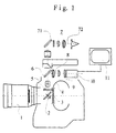
- a motion picture camera with video reflection shows a Shot lens 1 through which a shot beam path in the film camera enters and onto a rotating mirror screen 2 hits.
- the rotating mirror cover 2 settles 2 from a semicircular mirror surface 21 with a circumferential angle of usually 180 ° and one Aperture adjustment wing arranged coaxially to the mirror surface 21 22 together, opposite the mirror surface 21 is adjustable, so that theoretically aperture angle ⁇ from 0 ° to 180 ° of the rotating mirror diaphragm 2 can be.
- the receiving beam path hits the opening sector (Bright sector) and passes through it as a film exposure beam path through a picture window 3 onto one in one Film channel-guided motion picture film 4.
- the picture window 3 through the mirror surface 21 of the rotating mirror cover 2 covered and the recording beam path as viewfinder and video beam path distracted on a matt screen or fiberboard 5, from where from the beam path offset in parallel by a deflection device arrives at a beam splitter 6, which of the the rotating mirror diaphragm 2 deflected exposure beam path into a viewfinder beam path and a video beam path splits.
- the viewfinder beam path passes through a face plate 71 and an eyepiece 72 of a viewfinder lens 7.
- the eyepiece 72 enables while considering the between the face plate 71 and the eyepiece 72 generated as an aerial viewfinder image.
- Video signal can be forwarded or processed and, for example, a monitor 11 which are shown a video image of the subject can, or be fed to a video recorder, that saves the video recordings.
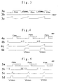
- Figures 3a, 4a and 5a illustrate in a schematic, temporal representation of the motion picture film and the CCD image converter of the video reflection device Amounts of light at different aperture angles.
- Figure 4a shows that at an aperture angle of 90 ° due to the 180 ° mirror surface 21 of the rotating mirror diaphragm 2 an unchanged amount of light on the CCD image converter would fall while the one coming onto the motion picture film
- the amount of light is halved (the shaded area indicates the suppression of the film exposure beam path by the Aperture adjustment wing opposite its full opening an), so that the relationship between the amount of film light and Video light quantity would be 1: 2.
- Figure 2 shows the in a schematic block diagram Circuit arrangement for realizing a from Aperture angle dependent exposure control of the CCD image sensor.
- the adjustable orifice 2 consists in the above described way from a semicircular disk-shaped Mirror surface 21 and an aperture 22, the coaxial to the semicircular disk-shaped mirror surface 21 arranged and manual or motorized at a standstill or in Run relative to the mirror surface 21 is adjustable.
- the Aperture opening angle ⁇ determined at a given circulation speed the adjustable orifice plate 2 or transport speed of the motion picture film on the motion picture film amount of light falling to expose a film image.
- the aperture angle ⁇ can preferably by means of a potentiometer connected to the aperture adjustment shaft, by means of an electro-optical, magnetic or the like Sensor 31 and / or by means of an analog or digital Angle encoder 32 according to WO 90/08975 both in Standstill as well as be detected during the run. Both sensors 31, 32 can both be used to detect the aperture angle and the position of the orifice plate as well for one Fine correction can be used.
- the output signal of the sensor (s) 31, 32 is combined with one output by video electronics 10 Video clock signal fed to a microprocessor 12, the Output connected to the input of a clock generator 13 is. Is at another input of the clock generator 13 the video clock signal.
- the clock generator 13 controls one Aperture logic 14 and the CCD image converter 9 and one Readout circuit of the CCD image converter 9, which consists of a Sample and hold amplifier with automatic gain control (AGC) 16, an analog-to-digital converter 17, one Memory element 18 and a digital-to-analog converter 19 exists, the output of which is connected to video electronics 10 is.
- the video electronics 10 outputs both the video clock signal to the microprocessor 12 and the clock generator 13 as also the video signal to a recorder, one Monitor or the like.
- the aperture logic 14 is connected on the output side via a component 15 influencing the substrate voltage V SUB of the CCD image converter 9 to the CCD image converter 9, which is connected on the output side to an input of the sample and hold amplifier with automatic amplification control 16.
- CCD imager This consists of a large number of semiconductor components arranged in a matrix as a photoelectronic light receiver, which is a disassembly of the optical images designed by the camera lens in individual picture elements and their conversion into electrical ones Enable signals. They are with each other line by line connected, charge-coupled components (CCD elements) electrically connected, which come from them temporarily store electrical signals (charge pattern), before being called up by high-frequency clock pulses and converted into video signals. Your function relies on the shift of electrical charges in the Inside a CCD chain through from the outside to your control electrodes applied clock pulse voltages and a capacitive Decoupling of the resulting electrical signals a common signal output.
- CCD elements charge-coupled components
- FIG. 3a shows - as explained above - the amount of light falling on a film image and on the CCD image converter at an aperture angle of 180 °. Both the film image and the CCD image converter receive the same amount of light in their respective exposure phase.
- V SUB Figure 3b
- FIG. 4 shows exposure conditions of a film image and of the CCD imager with an aperture angle of 90 °.
- the amount of light falling on a film image is according to Figure 4a only 50% of the amount of light at an aperture angle of 180 °, since that's the cover of the picture window hatched by the aperture adjustment wing No space for film image exposure.
- the substrate voltage V SUB is clocked and the pulse sequence is delivered to the CCD image converter, so that the charge of the CCD image converter stored in this period of time is discharged again (FIG. 4b) ,
- the duration of the pulsed substrate voltage is controlled as a function of the aperture opening angle ⁇ , so that, according to FIG. 4c, the amount of charge stored in the CCD image converter after the clocked substrate voltage has ended corresponds to an exposure shown in FIG. 4d, which is equal to the exposure of the film image at an aperture opening angle of 45 ° is.
- FIG. 5 shows the corresponding signals shown an aperture angle of 45 °.
- the amounts of light shown in FIGS. 3 to 5 or Signals clarify that the video signal by constant Discharging the CCD imager in the fade-out time Film image exposure is adjusted so that the ratio of Exposure of the film image and the amplitude of the video signal Is 1: 1 and therefore independent of an automatic Gain of the video image an adaptation of the video signal at the aperture angle.
- the aperture control according to the invention can be carried out in an analogous manner also with CCD image converters with "progressive scan” appropriately adapted aperture logic can be applied.
Landscapes
- Physics & Mathematics (AREA)
- General Physics & Mathematics (AREA)
- Engineering & Computer Science (AREA)
- Multimedia (AREA)
- Signal Processing (AREA)
- Transforming Light Signals Into Electric Signals (AREA)
- Color Television Image Signal Generators (AREA)
- Studio Devices (AREA)
Description
- Figur 1 -
- eine schematische Darstellung des Strahlenganges in einer Laufbildkamera mit rotierender Spiegelblende und einer Videoausspiegelungseinrichtung;
- Figur 2 -
- ein Blockschaltbild der Videobildsteuerung und
- Figuren 3 bis 5 -
- schematische zeitliche Darstellungen der Filmbelichtung und Ansteuersignale des CCD-Bildwandlers bei unterschiedlichen Blendenöffnungswinkeln.
Claims (8)
- Verfahren zur Steuerung einer einen CCD-Bildwandler (9) und eine Videoelektronik (10) enthaltenden Videoausspiegelungseinrichtung (6, 8) für eine Laufbild-Filmaufnahmekamera zum Transport und zur Belichtung eines Laufbildfilms (4) mit einer verstellbaren Spiegel- oder Umlaufblende (2), deren Spiegelfläche (Dunkelsektor 21, Blendenverstellflügel 22) den Aufnahmestrahlengang zumindest zur Videoausspiegelungseinrichtung (6, 8) reflektiert, deren Öffnungssektor (Hellsektor, Blendenöffnungswinkel α) den Aufnahmestrahlengang zur Filmbelichtung freigibt und deren Blendenöffnungswinkel (α) von einen Sensor (31, 32) erfaßt wird,
dadurch gekennzeichnet, daß die Belichtungszeit des CCD-Bildwandlers (9) in Abhängigkeit vom Blendenöffnungswinkel (α) gesteuert wird. - Verfahren nach Anspruch 1, dadurch gekennzeichnet, daß die Belichtungszeit des CCD-Bildwandlers (9) mit steigendem Blendenöffnungswinkel (α) verlängert, vorzugsweise gleich der Filmbelichtungszeit eingestellt wird.
- Verfahren nach Anspruch 1 oder 2, dadurch gekennzeichnet, daß zur Veränderung zur Belichtungszeit des CCD-Bildwandlers (9) der Zeitpunkt und die Zeitdauer der Aufladung des CCD-Bildwandlers (9) in Abhängigkeit vom Blendenöffnungswinkel (α) festgelegt wird.
- Verfahren nach mindestens einem der vorangehenden Ansprüche, dadurch gekennzeichnet, daß die Substratspannung (VSUB) des CCD-Bildwandlers (9) derart angesteuert wird, daß der CCD-Bildwandler (9) während der Ausblendung des Filmbelichtungs-Strahlenganges ständig entladen wird.
- Verfahren nach mindestens einem der vorangehenden Ansprüche 1 bis 3, dadurch gekennzeichnet, daß die Substratspannung (VSUB) des CCD-Bildwandlers (9) derart angesteuert wird, daß der CCD-Bildwandler (9) entladen wird bevor er in Abhängigkeit von der von der Blendenlogik (14) ermittelten Belichtungszeit des CCD-Bildwandlers (9) aufgeladen wird.
- Verfahren nach mindestens einem der vorangehenden Ansprüche, dadurch gekennzeichnet, daß die Videotaktfrequenz mit dem von einem ersten Sensor (31) erfaßten Blendenöffnungswinkel (α) und/oder der von einem zweiten Sensor (32) erfaßten Stellung der verstellbaren Umlaufblende (2) verknüpft wird.
- Vorrichtung zur Durchführung des Verfahrens nach mindestens einem der vorangehenden Ansprüche, dadurch gekennzeichnet, daß ein Mikroprozessor (12) eingangsseitig mit einem von der Videoelektronik (10) abgegebenen Videotaktsignal beaufschlagt wird und mit dem Ausgang mindestens eines den Blendenöffnungswinkel (α) und/oder die Stellung der verstellbaren Umlaufblende (2) erfassenden Sensors (31, 32) und ausgangsseitig mit einem Taktgenerator (13) verbunden ist,
und daß der ebenfalls mit dem Videotaktsignal beaufschlagte Taktgenerator (13) ausgangsseitig den CCD-Bildwandler (9) ansteuert und Ausgangssignale an eine Blendenlogik (14) abgibt, die diese Signale verknüpft und ein Steuersignal abgibt, mit dem die jeweils gespeicherte Ladung des CCD-Bildwandlers (9) wieder entladen wird, wenn der Blendenöffnungswinkel (α) der verstellbaren Umlaufblende (2) von einem vorgegebenen Wert abweicht. - Vorrichtung nach Anspruch 7, dadurch gekennzeichnet, daß die Blendenlogik (14) das Steuersignal an ein nachgeschaltetes, die Substratspannung des CCD-Bildwandlers (9) beeinflussendes Bauelement (15) abgibt, das die Substratspannung zur Entladung des CCD-Bildwandlers (9) taktet.
Applications Claiming Priority (3)
| Application Number | Priority Date | Filing Date | Title |
|---|---|---|---|
| DE19720148A DE19720148A1 (de) | 1997-05-02 | 1997-05-02 | Filmkamera mit einer Videoausspiegelungseinrichtung |
| DE19720148 | 1997-05-02 | ||
| PCT/DE1998/001286 WO1998051075A1 (de) | 1997-05-02 | 1998-05-04 | Verfahren zur steuerung einer einen ccd-bildwandler und eine videoelektronik enthaltenden videoausspiegelungseinrichtung für eine laufbild-filmaufnahmekamera |
Publications (2)
| Publication Number | Publication Date |
|---|---|
| EP0979577A1 EP0979577A1 (de) | 2000-02-16 |
| EP0979577B1 true EP0979577B1 (de) | 2002-02-13 |
Family
ID=7829407
Family Applications (1)
| Application Number | Title | Priority Date | Filing Date |
|---|---|---|---|
| EP98933483A Expired - Lifetime EP0979577B1 (de) | 1997-05-02 | 1998-05-04 | Verfahren zur steuerung einer einen ccd-bildwandler und eine videoelektronik enthaltenden videoausspiegelungseinrichtung für eine laufbild-filmaufnahmekamera |
Country Status (5)
| Country | Link |
|---|---|
| US (1) | US6757021B1 (de) |
| EP (1) | EP0979577B1 (de) |
| AT (1) | ATE213376T1 (de) |
| DE (2) | DE19720148A1 (de) |
| WO (1) | WO1998051075A1 (de) |
Families Citing this family (20)
| Publication number | Priority date | Publication date | Assignee | Title |
|---|---|---|---|---|
| EP1111443A1 (de) * | 1999-12-21 | 2001-06-27 | Peter Dipl.-Ing. Denz | Laufbildkamera mit einem durch ein Okular zu betrachtenden elekronischen Sucher |
| DE10210327B4 (de) * | 2002-03-08 | 2012-07-05 | Arnold & Richter Cine Technik Gmbh & Co. Betriebs Kg | Digitale Laufbildkamera |
| DE10218313B4 (de) | 2002-04-24 | 2018-02-15 | Arnold & Richter Cine Technik Gmbh & Co. Betriebs Kg | Digitale Laufbildkamera |
| DE10301714A1 (de) * | 2003-01-13 | 2004-07-29 | Arnold & Richter Cine Technik Gmbh & Co Betriebs Kg | Verfahren zum Verarbeiten von aus einem Filmaufnahmestrahlengang einer Laufbildkamera abgezweigten Filmbildern |
| DE102004004806B4 (de) | 2004-01-30 | 2012-04-19 | Arnold & Richter Cine Technik Gmbh & Co. Betriebs Kg | Elektronische Laufbildkamera |
| DE102005001652A1 (de) * | 2005-01-10 | 2006-07-20 | Arnold & Richter Cine Technik Gmbh & Co. Betriebs Kg | Verfahren zum Verarbeiten von aus einem Filmaufnahmestrahlengang einer Laufbildkamera abgezweigten Filmbildern |
| DE102005007911A1 (de) * | 2005-02-08 | 2006-08-10 | Hensoldt Ag | Kamera |
| DE102006031757A1 (de) * | 2006-01-04 | 2007-08-02 | Arnold & Richter Cine Technik Gmbh & Co. Betriebs Kg | Verfahren zur automatischen Korrektur von Bildfehlern in Video-Assist-Bildern eines Video-Assist-Systems |
| JP4645692B2 (ja) * | 2008-07-18 | 2011-03-09 | ソニー株式会社 | 撮像装置 |
| US9642606B2 (en) | 2012-06-27 | 2017-05-09 | Camplex, Inc. | Surgical visualization system |
| US10022041B2 (en) | 2012-06-27 | 2018-07-17 | Camplex, Inc. | Hydraulic system for surgical applications |
| DE102012218863A1 (de) * | 2012-10-16 | 2014-04-17 | Arnold & Richter Cine Technik Gmbh & Co. Betriebs Kg | Stereoskopisches Abbildungssystem |
| EP2999414B1 (de) | 2013-05-21 | 2018-08-08 | Camplex, Inc. | Chirurgische visualisierungssysteme |
| EP3046458B1 (de) | 2013-09-20 | 2020-10-21 | Camplex, Inc. | Chirurgische visualisierungssysteme |
| JP6521982B2 (ja) | 2013-09-20 | 2019-05-29 | キャンプレックス インコーポレイテッド | 手術可視化システム及びディスプレイ |
| EP3226799A4 (de) | 2014-12-05 | 2018-07-25 | Camplex, Inc. | Chirurgische visualisierungssysteme und anzeigen |
| US11154378B2 (en) | 2015-03-25 | 2021-10-26 | Camplex, Inc. | Surgical visualization systems and displays |
| US10966798B2 (en) | 2015-11-25 | 2021-04-06 | Camplex, Inc. | Surgical visualization systems and displays |
| US10918455B2 (en) | 2017-05-08 | 2021-02-16 | Camplex, Inc. | Variable light source |
| CN114979442B (zh) * | 2022-05-25 | 2023-10-31 | 西南科技大学 | 一种多路图像采集装置及其控制方法 |
Family Cites Families (12)
| Publication number | Priority date | Publication date | Assignee | Title |
|---|---|---|---|---|
| US3114002A (en) * | 1960-01-08 | 1963-12-10 | Fernseh Gmbh | Combined television and cinematographic camera |
| DE3344274A1 (de) * | 1982-12-07 | 1984-06-07 | Canon K.K., Tokio/Tokyo | Bildaufnahme-einrichtung mit einer belichtungssteuereinrichtung |
| JPS59115676A (ja) * | 1982-12-22 | 1984-07-04 | Canon Inc | 撮像装置 |
| US4532550A (en) * | 1984-01-31 | 1985-07-30 | Rca Corporation | Exposure time control for a solid-state color camera |
| US4571629A (en) * | 1984-07-12 | 1986-02-18 | Fuji Photo Optical Co., Ltd. | Rotary shutter device |
| US4928171A (en) * | 1987-10-30 | 1990-05-22 | Panavision, Inc. | Video assist system for motion-picture camera |
| DE3833823C1 (de) | 1988-10-05 | 1990-02-22 | Arnold & Richter Cine Technik Gmbh & Co Betriebs Kg, 8000 Muenchen, De | |
| NL8802818A (de) | 1988-11-16 | 1990-06-18 | Philips Nv | |
| DE3902688A1 (de) | 1989-01-30 | 1990-08-09 | Arnold & Richter Kg | Verstellbare umlaufblende |
| DE4211427C2 (de) | 1992-04-01 | 2002-11-14 | Arnold & Richter Kg | Verfahren zum Reduzieren des Helligkeitsflimmerns von Videobildern |
| JP3240339B2 (ja) * | 1993-11-16 | 2001-12-17 | コニカ株式会社 | 画像撮影装置及び画像処理装置 |
| JPH08111819A (ja) | 1994-10-11 | 1996-04-30 | Sony Corp | タイミング発生回路、この回路を用いた固体撮像装置及びこの装置を搭載したビデオカメラ |
-
1997
- 1997-05-02 DE DE19720148A patent/DE19720148A1/de not_active Withdrawn
-
1998
- 1998-05-04 EP EP98933483A patent/EP0979577B1/de not_active Expired - Lifetime
- 1998-05-04 US US09/423,177 patent/US6757021B1/en not_active Expired - Fee Related
- 1998-05-04 AT AT98933483T patent/ATE213376T1/de not_active IP Right Cessation
- 1998-05-04 WO PCT/DE1998/001286 patent/WO1998051075A1/de not_active Ceased
- 1998-05-04 DE DE59803070T patent/DE59803070D1/de not_active Expired - Lifetime
Also Published As
| Publication number | Publication date |
|---|---|
| EP0979577A1 (de) | 2000-02-16 |
| DE59803070D1 (de) | 2002-03-21 |
| DE19720148A1 (de) | 1998-11-05 |
| ATE213376T1 (de) | 2002-02-15 |
| WO1998051075A1 (de) | 1998-11-12 |
| US6757021B1 (en) | 2004-06-29 |
Similar Documents
| Publication | Publication Date | Title |
|---|---|---|
| WO1998051075A1 (de) | Verfahren zur steuerung einer einen ccd-bildwandler und eine videoelektronik enthaltenden videoausspiegelungseinrichtung für eine laufbild-filmaufnahmekamera | |
| DE3530778C2 (de) | Endoskop mit einer festkoerper-bildaufnahmevorrichtung | |
| DE3855466T2 (de) | Stehbildvideokamera | |
| DE3432229C2 (de) | Bildaufnahmevorrichtung | |
| DE3344274C2 (de) | ||
| DE2930636C2 (de) | ||
| DE69114972T2 (de) | Festkörper-Bildaufnahmevorrichtungen. | |
| AT389964B (de) | Festkoerper-bildaufnahmeeinrichtung | |
| DE3700412C2 (de) | ||
| DE3631929C2 (de) | ||
| DE3718603C2 (de) | Farbbild-abtastvorrichtung, sowie elektronisches endoskop hiermit | |
| DE3787359T2 (de) | Elektronische Stehbildkamera. | |
| DE2559559A1 (de) | Kamera mit belichtungsmessystem | |
| DE3243920C2 (de) | ||
| DE2844339A1 (de) | Bewegungs-erfassungsvorrichtung in einem belichtungssteuerungssystem fuer optische geraete | |
| DE3913803A1 (de) | Belichtungsregeleinrichtung | |
| DE69215323T2 (de) | Schwarzabgleichseinstellung für mit mehreren Festkörper-Bildaufnahmevorrichtungen versehene Videokameras | |
| DE3405808C2 (de) | ||
| DE10338681A1 (de) | Digitalkamera | |
| EP0589002A1 (de) | Elektronische hochgeschwindigkeitskamera. | |
| DE4117020C2 (de) | Steuervorrichtung für einen Bildsensor | |
| DE4117019A1 (de) | Steuervorrichtung fuer einen bildsensor | |
| DE3743090C2 (de) | ||
| DE3833823C1 (de) | ||
| DE10017353A1 (de) | Einrichtung zur Korrektion des Zitterns eines fokussierten Bildes und mit dieser versehene Kamera |
Legal Events
| Date | Code | Title | Description |
|---|---|---|---|
| PUAI | Public reference made under article 153(3) epc to a published international application that has entered the european phase |
Free format text: ORIGINAL CODE: 0009012 |
|
| 17P | Request for examination filed |
Effective date: 19991022 |
|
| AK | Designated contracting states |
Kind code of ref document: A1 Designated state(s): AT DE FR GB IT |
|
| GRAG | Despatch of communication of intention to grant |
Free format text: ORIGINAL CODE: EPIDOS AGRA |
|
| 17Q | First examination report despatched |
Effective date: 20010423 |
|
| GRAG | Despatch of communication of intention to grant |
Free format text: ORIGINAL CODE: EPIDOS AGRA |
|
| GRAH | Despatch of communication of intention to grant a patent |
Free format text: ORIGINAL CODE: EPIDOS IGRA |
|
| GRAH | Despatch of communication of intention to grant a patent |
Free format text: ORIGINAL CODE: EPIDOS IGRA |
|
| GRAA | (expected) grant |
Free format text: ORIGINAL CODE: 0009210 |
|
| REG | Reference to a national code |
Ref country code: GB Ref legal event code: IF02 |
|
| AK | Designated contracting states |
Kind code of ref document: B1 Designated state(s): AT DE FR GB IT |
|
| REF | Corresponds to: |
Ref document number: 213376 Country of ref document: AT Date of ref document: 20020215 Kind code of ref document: T |
|
| REF | Corresponds to: |
Ref document number: 59803070 Country of ref document: DE Date of ref document: 20020321 |
|
| GBT | Gb: translation of ep patent filed (gb section 77(6)(a)/1977) |
Effective date: 20020418 |
|
| PGFP | Annual fee paid to national office [announced via postgrant information from national office to epo] |
Ref country code: FR Payment date: 20020517 Year of fee payment: 5 |
|
| PGFP | Annual fee paid to national office [announced via postgrant information from national office to epo] |
Ref country code: AT Payment date: 20020523 Year of fee payment: 5 |
|
| ET | Fr: translation filed | ||
| PLBE | No opposition filed within time limit |
Free format text: ORIGINAL CODE: 0009261 |
|
| STAA | Information on the status of an ep patent application or granted ep patent |
Free format text: STATUS: NO OPPOSITION FILED WITHIN TIME LIMIT |
|
| 26N | No opposition filed |
Effective date: 20021114 |
|
| PG25 | Lapsed in a contracting state [announced via postgrant information from national office to epo] |
Ref country code: AT Free format text: LAPSE BECAUSE OF NON-PAYMENT OF DUE FEES Effective date: 20030504 |
|
| PG25 | Lapsed in a contracting state [announced via postgrant information from national office to epo] |
Ref country code: FR Free format text: LAPSE BECAUSE OF NON-PAYMENT OF DUE FEES Effective date: 20040130 |
|
| REG | Reference to a national code |
Ref country code: FR Ref legal event code: ST |
|
| PG25 | Lapsed in a contracting state [announced via postgrant information from national office to epo] |
Ref country code: IT Free format text: LAPSE BECAUSE OF NON-PAYMENT OF DUE FEES Effective date: 20050504 |
|
| PGFP | Annual fee paid to national office [announced via postgrant information from national office to epo] |
Ref country code: GB Payment date: 20130522 Year of fee payment: 16 Ref country code: DE Payment date: 20130409 Year of fee payment: 16 |
|
| REG | Reference to a national code |
Ref country code: DE Ref legal event code: R119 Ref document number: 59803070 Country of ref document: DE |
|
| GBPC | Gb: european patent ceased through non-payment of renewal fee |
Effective date: 20140504 |
|
| REG | Reference to a national code |
Ref country code: DE Ref legal event code: R119 Ref document number: 59803070 Country of ref document: DE Effective date: 20141202 |
|
| PG25 | Lapsed in a contracting state [announced via postgrant information from national office to epo] |
Ref country code: DE Free format text: LAPSE BECAUSE OF NON-PAYMENT OF DUE FEES Effective date: 20141202 |
|
| PG25 | Lapsed in a contracting state [announced via postgrant information from national office to epo] |
Ref country code: GB Free format text: LAPSE BECAUSE OF NON-PAYMENT OF DUE FEES Effective date: 20140504 |