EP0979365B1 - Fahrzeuggetriebe mit integrierter gekühlter bremse - Google Patents
Fahrzeuggetriebe mit integrierter gekühlter bremse Download PDFInfo
- Publication number
- EP0979365B1 EP0979365B1 EP98925485A EP98925485A EP0979365B1 EP 0979365 B1 EP0979365 B1 EP 0979365B1 EP 98925485 A EP98925485 A EP 98925485A EP 98925485 A EP98925485 A EP 98925485A EP 0979365 B1 EP0979365 B1 EP 0979365B1
- Authority
- EP
- European Patent Office
- Prior art keywords
- vehicle transmission
- accordance
- brake
- discs
- gear
- Prior art date
- Legal status (The legal status is an assumption and is not a legal conclusion. Google has not performed a legal analysis and makes no representation as to the accuracy of the status listed.)
- Expired - Lifetime
Links
- 230000005540 biological transmission Effects 0.000 claims description 40
- 239000002826 coolant Substances 0.000 claims description 16
- 230000001133 acceleration Effects 0.000 claims description 3
- 239000002131 composite material Substances 0.000 claims description 2
- 239000002184 metal Substances 0.000 claims 1
- 238000005266 casting Methods 0.000 description 2
- 238000010276 construction Methods 0.000 description 2
- 239000011324 bead Substances 0.000 description 1
- 238000001816 cooling Methods 0.000 description 1
- 230000001737 promoting effect Effects 0.000 description 1
Images

Classifications
-
- B—PERFORMING OPERATIONS; TRANSPORTING
- B60—VEHICLES IN GENERAL
- B60T—VEHICLE BRAKE CONTROL SYSTEMS OR PARTS THEREOF; BRAKE CONTROL SYSTEMS OR PARTS THEREOF, IN GENERAL; ARRANGEMENT OF BRAKING ELEMENTS ON VEHICLES IN GENERAL; PORTABLE DEVICES FOR PREVENTING UNWANTED MOVEMENT OF VEHICLES; VEHICLE MODIFICATIONS TO FACILITATE COOLING OF BRAKES
- B60T1/00—Arrangements of braking elements, i.e. of those parts where braking effect occurs specially for vehicles
- B60T1/02—Arrangements of braking elements, i.e. of those parts where braking effect occurs specially for vehicles acting by retarding wheels
- B60T1/06—Arrangements of braking elements, i.e. of those parts where braking effect occurs specially for vehicles acting by retarding wheels acting otherwise than on tread, e.g. employing rim, drum, disc, or transmission or on double wheels
- B60T1/062—Arrangements of braking elements, i.e. of those parts where braking effect occurs specially for vehicles acting by retarding wheels acting otherwise than on tread, e.g. employing rim, drum, disc, or transmission or on double wheels acting on transmission parts
-
- B—PERFORMING OPERATIONS; TRANSPORTING
- B60—VEHICLES IN GENERAL
- B60K—ARRANGEMENT OR MOUNTING OF PROPULSION UNITS OR OF TRANSMISSIONS IN VEHICLES; ARRANGEMENT OR MOUNTING OF PLURAL DIVERSE PRIME-MOVERS IN VEHICLES; AUXILIARY DRIVES FOR VEHICLES; INSTRUMENTATION OR DASHBOARDS FOR VEHICLES; ARRANGEMENTS IN CONNECTION WITH COOLING, AIR INTAKE, GAS EXHAUST OR FUEL SUPPLY OF PROPULSION UNITS IN VEHICLES
- B60K17/00—Arrangement or mounting of transmissions in vehicles
- B60K17/04—Arrangement or mounting of transmissions in vehicles characterised by arrangement, location or kind of gearing
- B60K17/043—Transmission unit disposed in on near the vehicle wheel, or between the differential gear unit and the wheel
- B60K17/046—Transmission unit disposed in on near the vehicle wheel, or between the differential gear unit and the wheel with planetary gearing having orbital motion
-
- F—MECHANICAL ENGINEERING; LIGHTING; HEATING; WEAPONS; BLASTING
- F16—ENGINEERING ELEMENTS AND UNITS; GENERAL MEASURES FOR PRODUCING AND MAINTAINING EFFECTIVE FUNCTIONING OF MACHINES OR INSTALLATIONS; THERMAL INSULATION IN GENERAL
- F16D—COUPLINGS FOR TRANSMITTING ROTATION; CLUTCHES; BRAKES
- F16D55/00—Brakes with substantially-radial braking surfaces pressed together in axial direction, e.g. disc brakes
- F16D55/24—Brakes with substantially-radial braking surfaces pressed together in axial direction, e.g. disc brakes with a plurality of axially-movable discs, lamellae, or pads, pressed from one side towards an axially-located member
- F16D55/26—Brakes with substantially-radial braking surfaces pressed together in axial direction, e.g. disc brakes with a plurality of axially-movable discs, lamellae, or pads, pressed from one side towards an axially-located member without self-tightening action
- F16D55/36—Brakes with a plurality of rotating discs all lying side by side
- F16D55/40—Brakes with a plurality of rotating discs all lying side by side actuated by a fluid-pressure device arranged in or one the brake
-
- F—MECHANICAL ENGINEERING; LIGHTING; HEATING; WEAPONS; BLASTING
- F16—ENGINEERING ELEMENTS AND UNITS; GENERAL MEASURES FOR PRODUCING AND MAINTAINING EFFECTIVE FUNCTIONING OF MACHINES OR INSTALLATIONS; THERMAL INSULATION IN GENERAL
- F16D—COUPLINGS FOR TRANSMITTING ROTATION; CLUTCHES; BRAKES
- F16D65/00—Parts or details
- F16D65/38—Slack adjusters
- F16D65/40—Slack adjusters mechanical
- F16D65/42—Slack adjusters mechanical non-automatic
- F16D65/46—Slack adjusters mechanical non-automatic with screw-thread and nut
-
- F—MECHANICAL ENGINEERING; LIGHTING; HEATING; WEAPONS; BLASTING
- F16—ENGINEERING ELEMENTS AND UNITS; GENERAL MEASURES FOR PRODUCING AND MAINTAINING EFFECTIVE FUNCTIONING OF MACHINES OR INSTALLATIONS; THERMAL INSULATION IN GENERAL
- F16D—COUPLINGS FOR TRANSMITTING ROTATION; CLUTCHES; BRAKES
- F16D65/00—Parts or details
- F16D65/78—Features relating to cooling
- F16D65/84—Features relating to cooling for disc brakes
- F16D65/853—Features relating to cooling for disc brakes with closed cooling system
Definitions
- the invention relates to a vehicle transmission with integrated brake.
- Such gears can be used in final drives of all types of work machines, e.g. B. wheel loader or industrial trucks, wheeled or tracked vehicles application Find.
- German patent DE 2 907 138 is a planetary gear as a final drive in a wheel head disclosed.
- a multi-disc brake on the axle bridge housing put on. The construction takes a lot Space in the axial and radial directions and is made up of many Parts assembled.
- DE-A 196 40 146 shows a wheel hub with a direct Multi-disc brake, in which the inner discs are non-rotatable are connected to a planet carrier and stand firmly.
- the Planet carrier is fixed on an axle bridge.
- the rotatable outer slats engage in a toothing a ring gear.
- the inner central wheel forms the drive and the ring gear the output. Because the planet carrier is rotatably held with this arrangement did not achieve the largest possible translation.
- the invention based on the generic DE-A-3 832 649, is based on the object of a vehicle transmission to create that in both the axial and radial directions takes up little space, made up of few parts and to integrate a brake to be cooled in it. It should be preferred make optimal use of the interior of a wheel rim.
- the vehicle transmission is a planetary transmission with one Sun gear as input, at least one planet gear, and a fixed ring gear.
- the planet gear or the Planet gears are mounted on a planet carrier, the as an output an output flange for holding a wheel drives.
- this gearbox one is called liquid-cooled Multi-disc brake integrated multi-disc brake integrated.
- the planet carrier holds its radial outer area the inner, rotating with the wheel speed Brake discs.
- the planet carrier or one containing the planet carrier Composite component pointing towards the wheel Cones on.
- the pin preferably guides over a driving toothing the torque on the output flange about.
- the output flange advantageously takes one Rim on. He preferably wears a seal that Seals the housing of the vehicle transmission.
- the output flange is advantageous in a wheel bearing Storage led. It is therefore indirect via the output flange the planet carrier is supported by its pins.
- the Length of the pin gives approximately the width of the bearing base on.
- the output flange is preferably through a central one or several screws accessible from outside via optional a counterholder or directly axially with the planet carrier or its cone clamped.
- the advantage of this Construction is that after loosening the screw the output flange is easy to remove from the outside.
- the advantage of this screw connection is the bearing clearance set. The separate assembly effort of Bearing adjustment is not necessary.
- the vehicle transmission housed in a wheel head the Ring gear is preferably supported in a hub carrier.
- the ring gear forms an annular flange through which the torque in the axle bridge housing is initiated.
- This wheel head is preferably to a funnel-shaped extension of an axle bridge housing connected, preferably over a large bolt circle.
- the torque acting on the ring gear can by attaching the ring gear to casting eyes of the funnel-shaped Extension of the axle bridge housing supported become.
- that acting on the ring gear Torque can be absorbed by the wheel head, which in turn is attached to the axle bridge housing.
- the ring gear forms an annular flange, which is fixed between the wheel head and the axle bridge housing is.
- the coolant circulation system for cooling the brake plates educated. Through holes in the planet carrier and / or grooving and / or beads on its outer diameter On the side of the brake discs, coolant gets to the Brake discs. From the centrifugal acceleration a promotional effect.
- the brake discs are advantageous crossed by grooves through which the coolant also adjacent slats can flow. Channels and / or recesses in the outer brake discs, in the ring gear and / or a hub carrier allow the coolant to drain.
- the grooves in the inner brake plates run preferably radial in the first approximation. This is how it finds out Coolant another centrifugal acceleration.
- the Coolant is on the radially outer edge of the plate pack hurled.
- the channels or recesses in the outer brake plates to the return flow of the coolant preferably axially.
- the coolant in the circumferential area between the cast eyes between the radial outer edge of the ring gear and the axle bridge housing flow through.
- An annular piston acting as a brake piston is preferably arranged concentrically with the wheel bearing.
- a plurality of individual pistons acting as brake pistons are arranged axially parallel around the wheel bearing.
- the brake piston or pistons can be readjusted when the brake wears, preferably by means of an end screw.
- the supply lines of the brake piston or pistons are advantageously arranged on the outer diameter of a hub carrier.
- the wear of the brake plates is preferably measured from the outside via a brake piston back or via a radial bore in a hub carrier or from the side of an axle bridge in each case by means of a locking screw.
- the brake piston or pistons are advantageously reset by means of springs.
- the return springs are preferably attached to the eyes on the radially outer edge of the brake plates between the last of the outer brake plates on the piston side. The return springs are supported at the other end on a non-rotatable component of the wheel head.
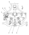
- FIG. 1 shows a final drive as a planetary gear designed vehicle transmission 1.
- a sun gear 2 drives on at least one planet gear 3 that a fixed ring gear 4 rolls off a planet carrier 5. This holds the inner on its radially outer area Brake discs 6 of a liquid-cooled multi-disc brake.
- the planet carrier 5 has an axial outwards, d. H. pin 7 pointing in the direction of the wheel, the output torque via driving teeth transfers the output flange 8. This is through one central screw 9 accessible from the outside via a counterholder 10 axially with the planet carrier 5 on its pin 7 braced.
- the output flange 8 takes one - not illustrated - rim on. He wears a seal 11 that seals the housing 12 of the vehicle transmission 1.
- the housing 12 of the vehicle transmission 1 is divided in such a way that a component 16 the wheel bearing and receives the outer, standing brake plates 6.
- the Housing 12 of the vehicle transmission 1 is large Bolt circle to a funnel-shaped extension 17 one Axle bridge housing 18 connected.
- the ring gear 4 formed as an annular flange 19 between the housing 12 of the vehicle transmission 1 and the axle bridge housing 18 is arranged and together with the housing 12 of the vehicle transmission 1 is screwed to the axle bridge housing 18.
- the lead 20 of the brake piston is on the outside diameter of the housing 12 acting as a hub carrier.
- FIG. 2 shows a technical variant of this in a final drive as a planetary gear designed vehicle transmission 1.
- the output flange 108 is through a central screw 109 directly accessible from the outside axially with the planet carrier 105 on its pin 107 tense.
- the ring gear is 104 directly on cast eyes 121 of the axle bridge housing 118 attached.
- the torque acting on the ring gear 104 becomes supported on adapter sleeves in the bores of the ring gear 104 and the cast eyes 121 of the axle bridge housing 118 are plugged in.
Landscapes
- Engineering & Computer Science (AREA)
- General Engineering & Computer Science (AREA)
- Mechanical Engineering (AREA)
- Transportation (AREA)
- Chemical & Material Sciences (AREA)
- Combustion & Propulsion (AREA)
- Braking Arrangements (AREA)
- Retarders (AREA)
- General Details Of Gearings (AREA)
Description
In einer anderen vorteilhaften Ausgestaltung der Erfindung sind mehrere als Bremskolben wirkende Einzelkolben achsparallel rund um die Radlagerung angeordnet.
In einer vorteilhaften Ausgestaltung der Erfindung können der oder die Bremskolben bei Verschleiß der Bremse nachgestellt werden, vorzugsweise durch eine stirnseitige Schraube. Die Zuleitungen des oder der Bremskolben sind vorteilhaft am Außendurchmesser eines Nabenträgers angeordnet. Vorzugsweise wird der Verschleiß der Bremslamellen über einen Bremskolbenrücken von außen oder über eine radiale Bohrung in einem Nabenträger oder von der Seite einer Achsbrücke jeweils über eine Verschlußschraube gemessen. Der oder die Bremskolben werden vorteilhaft mittels Federn zurückgestellt. Dabei sind die Rückstellfedern vorzugsweise zwischen der kolbenseitig letzten der äußeren Bremslamellen an Augen an dem radial äußeren Rand der Bremslamellen angebracht. Die Rückstellfedern stützen sich am anderen Ende an einem drehfesten Bauteil des Radkopfs ab.
- Figur 1
- ein in einem Endabtrieb als Planetengetriebe ausgestaltetes Fahrzeuggetriebe;
- Figur 2
- eine technische Variante hierzu.
- 1
- Fahrzeuggetriebe
- 2
- Sonnenrad
- 3
- Planetenrad
- 4
- Hohlrad
- 5
- Planetenträger
- 6
- Bremslamellen
- 7
- Zapfen
- 8
- Abtriebsflansch
- 9
- Schraube
- 10
- Gegenhalter
- 11
- Dichtung
- 12
- Gehäuse
- 13
- Lagerung
- 14
- Ringkolben
- 15
- Rückzugsfedern
- 16
- Bauteil
- 17
- trichterförmige Erweiterung
- 18
- Achsbrückengehäuse
- 19
- Ringflansch
- 20
- Zuleitung
- 104
- Hohlrad
- 105
- Planetenträger
- 107
- Zapfen
- 108
- Abtriebs flansch
- 109
- Schraube
- 117
- trichterförmige Erweiterung
- 118
- Achsbrückengehäuse
- 121
- Gußaugen
Claims (19)
- Fahrzeuggetriebe mit einem Sonnenrad (2) als Antrieb, mindestens einem Planetenrad (3), einem feststehenden Hohlrad (4;104), einem Planetenträger (5;105) als Abtrieb, einem Abtriebsflansch (8;108) zur Halterung eines Rades und einer Lamellenbremse, welche als in das Fahrzeuggetriebe integrierte flüssigkeitsgekühlte Mehrscheibenbremse ausgebildet ist,
dadurch gekennzeichnet, daßdie inneren drehenden Lamellen an dem radial äußeren Bereich des Planetenträgers und dem mindestens einem Planetenrad axial benachbart gehaltert sind unddie äußeren Lamellen in einem feststehenden Gehäuseteil (16) gehaltert sind, wobei sich aus der Zentrifugalbeschleunigung der sich drehenden Lamellen eine Förderwirkung für die Kühlflüssigkeit ergibt. - Fahrzeuggetriebe (1) nach Anspruch 1,
dadurch gekennzeichnet, daß
der Planetenträger (5, 105) oder ein den Planetenträger (5, 105) beinhaltendes Verbundbauteil einen in Richtung Rad zeigenden Zapfen (7, 107) aufweist. - Fahrzeuggetriebe (1) nach Anspruch 2,
dadurch gekennzeichnet, daß
der Zapfen (7, 107) über eine Mitnahmeverzahnung das Drehmoment auf den Abtriebsflansch (8, 108) überleitet. - Fahrzeuggetriebe (1) nach Anspruch 1,
dadurch gekennzeichnet, daß
der Abtriebsflansch (8, 108) eine Felge aufnimmt, eine Dichtung (11) trägt, die das Gehäuse (12) des Fahrzeuggetriebes (1) abdichtet, und in einer die Radlagerung bildenden Lagerung (13) geführt ist. - Fahrzeuggetriebe (1) nach Anspruch 1 - 4,
dadurch gekennzeichnet, daß
der Abtriebsflansch (8, 108) durch eine zentrale oder mehrere von außen zugängliche Schrauben (9, 109) wahlweise direkt oder über einen Gegenhalter (10) axial mit dem Planetenträger (5, 105) bzw. seinem Zapfen (7, 107) verspannt ist. - Fahrzeuggetriebe (1) nach Anspruch 1,
dadurch gekennzeichnet, daß
es in einem Radkopf untergebracht ist und daß das Hohlrad (4, 104) in einem Nabenträger abgestützt ist oder einen Ringflansch (19) bildet, über den das Drehmoment in das Achsbrückengehäuse (18) eingeleitet wird. - Fahrzeuggetriebe (1) nach Anspruch 1,
dadurch gekennzeichnet, daß
es in einem Radkopf untergebracht ist, der an eine trichterförmige Erweiterung (17, 117) eines Achsbrückengehäuses (18, 118) angeschlossen ist, insbesondere über einen großen Lochkreis in dieser trichterförmige Erweiterung (17, 117), wobei das auf das Hohlrad (4, 104) wirkende Drehmoment über den Radkopf oder durch die Befestigung des Hohlrades (104) an Gußaugen (121) der trichterförmigen Erweiterung (117) des Achsbrückengehäuses (118) abgestützt wird oder das Hohlrad (4) einen Ringflansch (19) bildet, der zwischen Radkopf und dem Achsbrückengehäuse (18) befestigt ist. - Fahrzeuggetriebe (1) nach Anspruch 1 - 3,
dadurch gekennzeichnet, daß
ein Bauteil (16) die Radlagerung und die äußeren, stehenden Bremslamellen (6) und wahlweise das Hohlrad aufnimmt. - Fahrzeuggetriebe (1) nach Anspruch 1,
dadurch gekennzeichnet, daß
ein Kühlflüssigkeitzirkulationsystem mittels Bohrungen im Planetenträger (5, 105) und/oder Nutung und/oder Sicken an dessen Außendurchmesser auf der Seite der Bremslamellen (6) und/oder Nuten in den Bremslamellen (6) und/oder Kanälen und/oder Aussparungen in den äußeren Bremslamellen und/oder dem Hohlrad (4, 104) und/oder einem Nabenträger ausgebildet ist. - Fahrzeuggetriebe (1) nach Anspruch 7 und 9,
dadurch gekennzeichnet, daß
der Rückfluß des Kühlmittels des Kühlflüssigkeitzirkulationsystems von der radial äußeren Seite der Bremslamellen (6) im Bereich der trichterförmigen Erweiterung (117) des Achsbrückengehäuses (118) zwischen den Gußaugen erfolgt. - Fahrzeuggetriebe (1) nach Anspruch 9 oder 10,
dadurch gekennzeichnet, daß
mittels eines trichterförmigen Blechs ein Kurzschluß von zu- und ablaufendem Kühlmittel des Kühlflüssigkeitzirkulationsystem in der Nähe des Planetenträgers (5, 105) vermieden wird. - Fahrzeuggetriebe (1) nach Anspruch 1,
dadurch gekennzeichnet, daß
ein als Bremskolben wirkender Ringkolben (14) konzentrisch zur Radlagerung angeordnet ist. - Fahrzeuggetriebe (1) nach Anspruch 1,
dadurch gekennzeichnet, daß
mehrere als Bremskolben wirkende Einzelkolben achsparallel rund um die Radlagerung angeordnet sind. - Fahrzeuggetriebe (1) nach Anspruch 12 oder 13,
dadurch gekennzeichnet, daß
der oder die Bremskolben bei Verschleiß der Bremse nachgestellt werden können, insbesondere durch eine stirnseitige Schraube. - Fahrzeuggetriebe (1) nach Anspruch 12 oder 13,
dadurch gekennzeichnet, daß
die Zuleitungen (20) des oder der Bremskolben am Außendurchmesser eines Nabenträgers angeordnet sind. - Fahrzeuggetriebe (1) nach Anspruch 12 oder 13,
dadurch gekennzeichnet, daß
der Verschleiß der Bremslamellen (6) über einen Bremskolbenrücken von außen oder über eine radiale Bohrung in einem Nabenträger oder von der Seite einer Achsbrücke jeweils über eine Verschlußschraube gemessen wird. - Fahrzeuggetriebe (1) nach Anspruch 12 oder 13,
dadurch gekennzeichnet, daß
der oder die Bremskolben mittels Federn zurückgestellt werden. - Fahrzeuggetriebe (1) nach Anspruch 17,
dadurch gekennzeichnet, daß
die Rückstellfedern vorzugsweise zwischen der kolbenseitig letzten der äußeren Bremslamellen an Augen an dem radial äußeren Rand der Bremslamellen angebracht sind und sich am anderen Ende an einem drehfesten Bauteil des Radkopfs abstützen. - Fahrzeuggetriebe (1) nach Anspruch 1,
dadurch gekennzeichnet, daß
es in einem Achsbrückengehäuse (18) neben einem Ausgleichgetriebe untergebracht ist.
Priority Applications (1)
| Application Number | Priority Date | Filing Date | Title |
|---|---|---|---|
| DE29824986U DE29824986U1 (de) | 1997-05-02 | 1998-04-25 | Fahrzeuggetriebe mit integrierter Bremse |
Applications Claiming Priority (3)
| Application Number | Priority Date | Filing Date | Title |
|---|---|---|---|
| DE19718744A DE19718744C1 (de) | 1997-05-02 | 1997-05-02 | Fahrzeuggetriebe mit integrierter Bremse |
| DE19718744 | 1997-05-02 | ||
| PCT/EP1998/002469 WO1998050714A2 (de) | 1997-05-02 | 1998-04-25 | Fahrzeuggetriebe mit integrierter bremse |
Publications (3)
| Publication Number | Publication Date |
|---|---|
| EP0979365A2 EP0979365A2 (de) | 2000-02-16 |
| EP0979365B1 true EP0979365B1 (de) | 2001-07-11 |
| EP0979365B2 EP0979365B2 (de) | 2004-03-10 |
Family
ID=7828548
Family Applications (1)
| Application Number | Title | Priority Date | Filing Date |
|---|---|---|---|
| EP98925485A Expired - Lifetime EP0979365B2 (de) | 1997-05-02 | 1998-04-25 | Fahrzeuggetriebe mit integrierter gekühlter bremse |
Country Status (4)
| Country | Link |
|---|---|
| US (1) | US6817963B1 (de) |
| EP (1) | EP0979365B2 (de) |
| DE (2) | DE19718744C1 (de) |
| WO (1) | WO1998050714A2 (de) |
Cited By (2)
| Publication number | Priority date | Publication date | Assignee | Title |
|---|---|---|---|---|
| WO2004108460A1 (de) | 2003-06-06 | 2004-12-16 | Zf Friedrichshafen Ag | Antrieb für ein mobil-fahrzeug |
| DE102004013301A1 (de) * | 2004-03-18 | 2005-09-29 | Zf Friedrichshafen Ag | Lamellenbremse für ein Fahrzeuggetriebe |
Families Citing this family (34)
| Publication number | Priority date | Publication date | Assignee | Title |
|---|---|---|---|---|
| SE509788C2 (sv) * | 1997-07-18 | 1999-03-08 | Volvo Constr Equip Components | Planetväxel för ett fordonshjul |
| DE19854781A1 (de) | 1998-11-27 | 2000-05-31 | Zahnradfabrik Friedrichshafen | Lenkbarer Radantrieb |
| DE60123010T2 (de) * | 2001-02-23 | 2007-04-19 | Dana Italia S.P.A., Arco | Radnabe mit integriertem Planetengetriebe und Lamellenbremse |
| DE10217483A1 (de) * | 2002-04-19 | 2003-11-06 | Zahnradfabrik Friedrichshafen | Fahrzeuggetriebe zum Antrieb eines Rades |
| SE525626C2 (sv) * | 2003-03-05 | 2005-03-22 | Volvo Constr Equip Holding Se | Anordning för drivning av ett hjul hos ett fordon |
| DE10326139A1 (de) * | 2003-06-06 | 2005-01-13 | Zf Friedrichshafen Ag | Antriebe für Mobil-Fahrzeuge |
| US6869380B2 (en) | 2003-06-11 | 2005-03-22 | Zf Friedrichshafen Ag | Driveline for mobile-vehicles |
| US6890282B2 (en) | 2003-06-11 | 2005-05-10 | Zf Friedrichshafen Ag | Driveline for mobile vehicles |
| SE524860C2 (sv) * | 2003-09-26 | 2004-10-12 | Volvo Constr Equip Holding Se | Anordning för drivning av ett hjul hos ett fordon, samt en planethållare |
| DE10349905A1 (de) * | 2003-10-25 | 2005-05-25 | Zf Friedrichshafen Ag | Fahrzeuggetriebe mit integrierter Bremse |
| DE10351464A1 (de) * | 2003-11-04 | 2005-06-02 | Zf Friedrichshafen Ag | Mechanische Nachstellvorrichtung für den Betätigungskolben einer Lamellenbremse oder einer Lamellenkupplung |
| SE527256C2 (sv) * | 2004-06-30 | 2006-01-31 | Volvo Constr Equip Holding Se | Planettransmission, drivanordning innefattande planettransmissionen och bromslamell för planettransmissionen |
| EP1899619B1 (de) * | 2005-06-27 | 2013-06-19 | Volvo Construction Equipment AB | Planetengetriebe, antriebsvorrichtung und arbeitsfahrzeug |
| EP1910121B1 (de) * | 2005-07-01 | 2012-09-12 | Volvo Construction Equipment AB | Planetengetriebe, antriebsvorrichtung mit dem planetengetriebe und die antriebsvorrichtung umfassendes fahrzeug |
| US20070060440A1 (en) * | 2005-08-31 | 2007-03-15 | Pao-Ling Lee | Speed reduction system for generating high torque |
| DE102007017617B4 (de) * | 2006-11-02 | 2016-06-09 | Johnson Controls Gmbh | Verstelleinrichtung eines Kraftfahrzeugsitzes |
| WO2010005583A1 (en) | 2008-07-09 | 2010-01-14 | Mclaren Performance Technologies, Inc. | Axially compact support for a gear within a gearbox |
| US8028788B2 (en) * | 2009-02-19 | 2011-10-04 | Nmhg Oregon, Llc | Spring applied brake and drive axle assembly |
| US8893845B2 (en) | 2009-02-19 | 2014-11-25 | Nmhg Oregon, Llc | Multi-stage brake pedal linkage |
| CN103477111B (zh) | 2011-02-03 | 2016-06-22 | 沃尔沃建筑设备公司 | 用于向制动器供油的装置 |
| US8627737B2 (en) | 2011-03-16 | 2014-01-14 | Caterpillar Inc. | Spur gear final drive with integrated brakes |
| JP6009210B2 (ja) * | 2012-04-26 | 2016-10-19 | コベルコ建機株式会社 | 建設機械の駆動装置 |
| JP6170321B2 (ja) * | 2013-03-29 | 2017-07-26 | 住友重機械工業株式会社 | ショベル |
| EP2860336A3 (de) * | 2013-10-14 | 2018-01-03 | IMS Gear GmbH | Angetriebene Klappenanordnung für ein Kraftfahrzeug |
| CN104358804B (zh) * | 2014-10-29 | 2017-03-01 | 李开卫 | 多片湿式盘式制动器及其运行方法 |
| ES2935600T3 (es) * | 2015-09-04 | 2023-03-08 | Desch Antriebstechnik Gmbh & Co Kg | Engranaje planetario |
| US9759289B2 (en) * | 2015-09-21 | 2017-09-12 | Arvinmeritor Technology, Llc | Bogie axle assembly |
| EP3358088B1 (de) * | 2015-10-01 | 2021-12-08 | Volvo Construction Equipment AB | Schwenkeinheit für eine baumaschine |
| US10036449B2 (en) | 2015-11-03 | 2018-07-31 | Arvinmeritor Technology, Llc | Axle assembly having a sun gear positioning arrangement |
| US9834038B2 (en) * | 2015-11-03 | 2017-12-05 | Arvinmeritor Technology, Llc | Axle assembly having a bearing preload bolt |
| US10065455B2 (en) | 2015-11-03 | 2018-09-04 | Arvinmeritor Technology, Llc | Axle assembly having a wet disc brake |
| US9868322B1 (en) * | 2016-07-29 | 2018-01-16 | Arvinmeritor Technology, Llc | Axle assembly having a wheel mount disposed on a planet carrier |
| US11807199B2 (en) * | 2019-02-22 | 2023-11-07 | Super ATV, LLC | Portal braking system |
| DE102020203820B4 (de) | 2020-03-25 | 2022-12-08 | Zf Friedrichshafen Ag | Antriebseinheit für ein Flurförderzeug, Antriebsachse für ein Flurförderzeug und Flurförderzeug |
Family Cites Families (37)
| Publication number | Priority date | Publication date | Assignee | Title |
|---|---|---|---|---|
| US2776583A (en) | 1954-04-05 | 1957-01-08 | Rockwell Spring & Axle Co | Drive mechanism for crop harvesting vehicles |
| US2920722A (en) † | 1958-02-12 | 1960-01-12 | Gen Motors Corp | Brake-adjusting device |
| US2998735A (en) * | 1959-04-15 | 1961-09-05 | Massey Ferguson Inc | Drive axle gearing assembly |
| US3115204A (en) | 1960-11-16 | 1963-12-24 | Clark Equipment Co | Power wheel assembly |
| US3754625A (en) * | 1972-06-07 | 1973-08-28 | Allis Chalmers | Vehicle final drive with planetary gearing and friction brake |
| DE2357451C2 (de) * | 1973-11-17 | 1981-09-24 | Carl Hurth Maschinen- und Zahnradfabrik GmbH & Co, 8000 München | Radnabenantrieb mit Bremse |
| GB1464101A (en) † | 1974-05-08 | 1977-02-09 | Hine M | Vehicles |
| US4181042A (en) | 1976-12-13 | 1980-01-01 | Trw Inc. | Drive assembly |
| US4173269A (en) * | 1978-02-23 | 1979-11-06 | Clark Equipment Company | Wet brake or clutch |
| US4159657A (en) * | 1978-03-06 | 1979-07-03 | Clark Equipment Company | Planetary outer end |
| GB2043186A (en) * | 1979-02-15 | 1980-10-01 | Newton Transmissions Ltd | Oil immersed brake, bearing pump |
| JPS57104410A (en) * | 1980-12-22 | 1982-06-29 | Toyo Umpanki Co Ltd | Driving shaft device |
| DE3222261A1 (de) † | 1982-06-10 | 1983-12-15 | Mannesmann AG, 4000 Düsseldorf | Bremse fuer schwere fahrzeuge |
| US4655326A (en) | 1985-11-29 | 1987-04-07 | Dana Corporation | Cooling system for planetary wheel end with wet brake |
| HU203704B (en) * | 1987-09-28 | 1991-09-30 | Magyar Vagon Es Gepgyar | Epicyclic-gear carriage |
| US5024636A (en) * | 1989-06-27 | 1991-06-18 | Fairfield Manufacturing Company, Inc. | Planetary wheel hub |
| JP2769323B2 (ja) † | 1988-06-29 | 1998-06-25 | アイシン・エィ・ダブリュ株式会社 | 減速機付モータ駆動装置及び電動車両 |
| JPH02107859A (ja) * | 1988-07-07 | 1990-04-19 | Toyota Motor Corp | 遊星歯車装置 |
| DE3836457A1 (de) * | 1988-10-26 | 1990-05-03 | Fendt & Co Xaver | Drehmomentuebertragunseinheit |
| DE3900075A1 (de) * | 1989-01-03 | 1990-07-12 | Magyar Vagon Es Gepgyar | Radkopf fuer fahrzeuge |
| DE3905292A1 (de) | 1989-02-21 | 1990-08-23 | Linde Ag | Radantriebseinheit |
| DE4011022A1 (de) * | 1989-04-08 | 1990-10-11 | Zahnradfabrik Friedrichshafen | Triebachse |
| US5064530A (en) * | 1990-06-04 | 1991-11-12 | Caterpillar Inc. | Fluid contamination detecting apparatus |
| DE4206087C2 (de) | 1992-02-27 | 1994-01-27 | Linde Ag | Hydromechanischer Radantrieb |
| DE4206101C2 (de) * | 1992-02-27 | 1997-11-06 | Linde Ag | Hydromechanisches Antriebssystem |
| DE4206100B4 (de) | 1992-02-27 | 2004-09-16 | Linde Ag | Schaltbares Planetengetriebe |
| BR9202976A (pt) † | 1992-07-31 | 1994-02-01 | Rockwell Braseixos Sa | Reducao planetaria para eixos motrizes |
| JP3104819B2 (ja) * | 1992-09-24 | 2000-10-30 | 株式会社豊田自動織機製作所 | 湿式ディスクブレーキ |
| DE4338468C2 (de) † | 1992-11-26 | 1996-01-25 | Orenstein & Koppel Ag | Verfahren und Einrichtung zur Verschleißmessung an Lamellenbremsen |
| DE4300445C2 (de) * | 1993-01-09 | 2003-04-24 | Linde Ag | Selbsttragende Flurförderzeug-Antriebsachse |
| US5509864A (en) * | 1994-12-22 | 1996-04-23 | General Motors Corporation | Split ring axial positioner for planetary gear assembly |
| JPH08177992A (ja) * | 1994-12-28 | 1996-07-12 | Jatco Corp | 自動変速機のキャリヤ結合構造 |
| DE19500765A1 (de) * | 1995-01-13 | 1996-07-25 | Orenstein & Koppel Ag | Verfahren und Einrichtung zur Nachstellung einer, insbesondere in Öl laufenden, Lamellenbremse |
| US5645148A (en) * | 1995-06-23 | 1997-07-08 | Zf Padova S.P.A. | Transmission with built-in brake, particularly for vehicles |
| JP3722451B2 (ja) * | 1996-06-26 | 2005-11-30 | 株式会社小松製作所 | 自走車両 |
| DE19640146C1 (de) | 1996-09-28 | 1998-01-08 | Orenstein & Koppel Ag | Radnabe mit direkter Lamellenbremse |
| SE509788C2 (sv) | 1997-07-18 | 1999-03-08 | Volvo Constr Equip Components | Planetväxel för ett fordonshjul |
-
1997
- 1997-05-02 DE DE19718744A patent/DE19718744C1/de not_active Expired - Lifetime
-
1998
- 1998-04-25 US US09/403,423 patent/US6817963B1/en not_active Expired - Lifetime
- 1998-04-25 DE DE59801006T patent/DE59801006D1/de not_active Expired - Lifetime
- 1998-04-25 EP EP98925485A patent/EP0979365B2/de not_active Expired - Lifetime
- 1998-04-25 WO PCT/EP1998/002469 patent/WO1998050714A2/de not_active Ceased
Cited By (4)
| Publication number | Priority date | Publication date | Assignee | Title |
|---|---|---|---|---|
| WO2004108460A1 (de) | 2003-06-06 | 2004-12-16 | Zf Friedrichshafen Ag | Antrieb für ein mobil-fahrzeug |
| DE10326143A1 (de) * | 2003-06-06 | 2004-12-23 | Zf Friedrichshafen Ag | Antrieb für ein Mobil-Fahrzeug |
| DE102004013301A1 (de) * | 2004-03-18 | 2005-09-29 | Zf Friedrichshafen Ag | Lamellenbremse für ein Fahrzeuggetriebe |
| DE102004013301B4 (de) * | 2004-03-18 | 2020-11-05 | Zf Friedrichshafen Ag | Lamellenbremse für ein Fahrzeuggetriebe |
Also Published As
| Publication number | Publication date |
|---|---|
| EP0979365A2 (de) | 2000-02-16 |
| WO1998050714A2 (de) | 1998-11-12 |
| US6817963B1 (en) | 2004-11-16 |
| WO1998050714A3 (de) | 1999-04-15 |
| EP0979365B2 (de) | 2004-03-10 |
| DE59801006D1 (de) | 2001-08-16 |
| DE19718744C1 (de) | 1998-11-19 |
Similar Documents
| Publication | Publication Date | Title |
|---|---|---|
| EP0979365B2 (de) | Fahrzeuggetriebe mit integrierter gekühlter bremse | |
| EP1053147B1 (de) | Radnabe mit integriertem planetengetriebe und lamellenbremse | |
| DE2831458C2 (de) | Radantrieb für Arbeitsmaschinen, insbesondere für Kettenfahrzeuge | |
| DE69020351T2 (de) | Planetengetriebe. | |
| DE3900075A1 (de) | Radkopf fuer fahrzeuge | |
| DE3638862A1 (de) | Antriebsachse fuer fahrzeuge | |
| DE19805300B4 (de) | Nabenantrieb | |
| DE4206086B4 (de) | Modular aufgebautes Antriebssystem | |
| DE3013431A1 (de) | Radkopf fuer triebraeder von fahrzeugen | |
| DE10030441A1 (de) | Radantrieb mit integrierter dynamischer Betriebsbremse | |
| DE19702198A1 (de) | Automatikgetriebe in Planetenbauweise | |
| DE3639035A1 (de) | Antriebsachse fuer fahrzeuge | |
| DE2839791C2 (de) | ||
| DE69810419T2 (de) | Drehmomentwandler mit Wendegetriebe | |
| EP1595762B1 (de) | Radnabe | |
| EP2195176B1 (de) | Radlagerung eines flugzeugfahrwerks | |
| DE10258913A1 (de) | Radantrieb mit einem Planetengetriebe und einer Bremse | |
| DE102021116201B4 (de) | Getriebeanordnung | |
| DE102021116203B3 (de) | Getriebeanordnung | |
| EP1133404B1 (de) | Lenkbarer radantrieb | |
| DE102018126959A1 (de) | Bremssystem, Achsträgereinheit für ein niederfluriges Fahrzeug, niederfluriges Fahrzeug mit einer derartigen Achsträgereinheit und Antriebseinheit | |
| EP1631470B1 (de) | Antrieb für ein mobil-fahrzeug | |
| DE9318634U1 (de) | Schnellaufendes Schaltgetriebe | |
| DE29824986U1 (de) | Fahrzeuggetriebe mit integrierter Bremse | |
| WO2020035344A1 (de) | Getriebe, insbesondere für eine einzelradantriebseinheit |
Legal Events
| Date | Code | Title | Description |
|---|---|---|---|
| PUAI | Public reference made under article 153(3) epc to a published international application that has entered the european phase |
Free format text: ORIGINAL CODE: 0009012 |
|
| 17P | Request for examination filed |
Effective date: 19990803 |
|
| AK | Designated contracting states |
Kind code of ref document: A2 Designated state(s): DE FR IT |
|
| RTI1 | Title (correction) |
Free format text: AUTOMOTIVE GEARBOX WITH AN INTEGRATED AND COOLED BRAKE |
|
| GRAG | Despatch of communication of intention to grant |
Free format text: ORIGINAL CODE: EPIDOS AGRA |
|
| GRAG | Despatch of communication of intention to grant |
Free format text: ORIGINAL CODE: EPIDOS AGRA |
|
| 17Q | First examination report despatched |
Effective date: 20001109 |
|
| GRAG | Despatch of communication of intention to grant |
Free format text: ORIGINAL CODE: EPIDOS AGRA |
|
| GRAH | Despatch of communication of intention to grant a patent |
Free format text: ORIGINAL CODE: EPIDOS IGRA |
|
| GRAH | Despatch of communication of intention to grant a patent |
Free format text: ORIGINAL CODE: EPIDOS IGRA |
|
| ITF | It: translation for a ep patent filed | ||
| GRAH | Despatch of communication of intention to grant a patent |
Free format text: ORIGINAL CODE: EPIDOS IGRA |
|
| GRAA | (expected) grant |
Free format text: ORIGINAL CODE: 0009210 |
|
| AK | Designated contracting states |
Kind code of ref document: B1 Designated state(s): DE FR IT |
|
| REF | Corresponds to: |
Ref document number: 59801006 Country of ref document: DE Date of ref document: 20010816 |
|
| ET | Fr: translation filed | ||
| PLBQ | Unpublished change to opponent data |
Free format text: ORIGINAL CODE: EPIDOS OPPO |
|
| PLBI | Opposition filed |
Free format text: ORIGINAL CODE: 0009260 |
|
| PLBF | Reply of patent proprietor to notice(s) of opposition |
Free format text: ORIGINAL CODE: EPIDOS OBSO |
|
| 26 | Opposition filed |
Opponent name: LINDE AKTIENGESELLSCHAFT Effective date: 20020408 |
|
| PLBF | Reply of patent proprietor to notice(s) of opposition |
Free format text: ORIGINAL CODE: EPIDOS OBSO |
|
| PLBF | Reply of patent proprietor to notice(s) of opposition |
Free format text: ORIGINAL CODE: EPIDOS OBSO |
|
| PLAW | Interlocutory decision in opposition |
Free format text: ORIGINAL CODE: EPIDOS IDOP |
|
| RTI2 | Title (correction) |
Free format text: AUTOMOTIVE GEARBOX WITH AN INTEGRATED AND COOLED BRAKE |
|
| RTI2 | Title (correction) |
Free format text: AUTOMOTIVE GEARBOX WITH AN INTEGRATED AND COOLED BRAKE |
|
| PLAW | Interlocutory decision in opposition |
Free format text: ORIGINAL CODE: EPIDOS IDOP |
|
| PUAH | Patent maintained in amended form |
Free format text: ORIGINAL CODE: 0009272 |
|
| STAA | Information on the status of an ep patent application or granted ep patent |
Free format text: STATUS: PATENT MAINTAINED AS AMENDED |
|
| 27A | Patent maintained in amended form |
Effective date: 20040310 |
|
| AK | Designated contracting states |
Kind code of ref document: B2 Designated state(s): DE FR IT |
|
| ET3 | Fr: translation filed ** decision concerning opposition | ||
| PGFP | Annual fee paid to national office [announced via postgrant information from national office to epo] |
Ref country code: FR Payment date: 20060410 Year of fee payment: 9 |
|
| PGFP | Annual fee paid to national office [announced via postgrant information from national office to epo] |
Ref country code: IT Payment date: 20060430 Year of fee payment: 9 |
|
| PG25 | Lapsed in a contracting state [announced via postgrant information from national office to epo] |
Ref country code: FR Free format text: LAPSE BECAUSE OF NON-PAYMENT OF DUE FEES Effective date: 20070430 |
|
| PG25 | Lapsed in a contracting state [announced via postgrant information from national office to epo] |
Ref country code: IT Free format text: LAPSE BECAUSE OF NON-PAYMENT OF DUE FEES Effective date: 20070425 |
|
| PGFP | Annual fee paid to national office [announced via postgrant information from national office to epo] |
Ref country code: DE Payment date: 20170420 Year of fee payment: 20 |
|
| REG | Reference to a national code |
Ref country code: DE Ref legal event code: R071 Ref document number: 59801006 Country of ref document: DE |