EP0978690A2 - Dispositif de purification d'air - Google Patents
Dispositif de purification d'air Download PDFInfo
- Publication number
- EP0978690A2 EP0978690A2 EP99107320A EP99107320A EP0978690A2 EP 0978690 A2 EP0978690 A2 EP 0978690A2 EP 99107320 A EP99107320 A EP 99107320A EP 99107320 A EP99107320 A EP 99107320A EP 0978690 A2 EP0978690 A2 EP 0978690A2
- Authority
- EP
- European Patent Office
- Prior art keywords
- photocatalyst
- sheet
- air cleaning
- cleaning unit
- particles
- Prior art date
- Legal status (The legal status is an assumption and is not a legal conclusion. Google has not performed a legal analysis and makes no representation as to the accuracy of the status listed.)
- Withdrawn
Links
- 238000004140 cleaning Methods 0.000 title claims abstract description 47
- 239000011941 photocatalyst Substances 0.000 claims abstract description 134
- 239000002245 particle Substances 0.000 claims abstract description 61
- -1 polytetrafluoroethylene Polymers 0.000 claims abstract description 30
- 239000004810 polytetrafluoroethylene Substances 0.000 claims abstract description 28
- 229920001343 polytetrafluoroethylene Polymers 0.000 claims abstract description 28
- 229920005989 resin Polymers 0.000 claims abstract description 23
- 239000011347 resin Substances 0.000 claims abstract description 23
- 239000000758 substrate Substances 0.000 claims abstract description 19
- 239000011800 void material Substances 0.000 claims description 15
- GWEVSGVZZGPLCZ-UHFFFAOYSA-N Titan oxide Chemical compound O=[Ti]=O GWEVSGVZZGPLCZ-UHFFFAOYSA-N 0.000 claims description 10
- OKTJSMMVPCPJKN-UHFFFAOYSA-N Carbon Chemical compound [C] OKTJSMMVPCPJKN-UHFFFAOYSA-N 0.000 claims description 8
- OGIDPMRJRNCKJF-UHFFFAOYSA-N titanium oxide Inorganic materials [Ti]=O OGIDPMRJRNCKJF-UHFFFAOYSA-N 0.000 claims description 8
- 229920002134 Carboxymethyl cellulose Polymers 0.000 claims description 4
- RYGMFSIKBFXOCR-UHFFFAOYSA-N Copper Chemical compound [Cu] RYGMFSIKBFXOCR-UHFFFAOYSA-N 0.000 claims description 4
- XLOMVQKBTHCTTD-UHFFFAOYSA-N Zinc monoxide Chemical compound [Zn]=O XLOMVQKBTHCTTD-UHFFFAOYSA-N 0.000 claims description 4
- 235000010948 carboxy methyl cellulose Nutrition 0.000 claims description 4
- 239000001768 carboxy methyl cellulose Substances 0.000 claims description 4
- 239000008112 carboxymethyl-cellulose Substances 0.000 claims description 4
- 229910052802 copper Inorganic materials 0.000 claims description 4
- 239000010949 copper Substances 0.000 claims description 4
- 239000002781 deodorant agent Substances 0.000 claims description 4
- HNPSIPDUKPIQMN-UHFFFAOYSA-N dioxosilane;oxo(oxoalumanyloxy)alumane Chemical compound O=[Si]=O.O=[Al]O[Al]=O HNPSIPDUKPIQMN-UHFFFAOYSA-N 0.000 claims description 4
- 229910021536 Zeolite Inorganic materials 0.000 claims description 3
- 239000010457 zeolite Substances 0.000 claims description 3
- WUPHOULIZUERAE-UHFFFAOYSA-N 3-(oxolan-2-yl)propanoic acid Chemical compound OC(=O)CCC1CCCO1 WUPHOULIZUERAE-UHFFFAOYSA-N 0.000 claims description 2
- 229910052980 cadmium sulfide Inorganic materials 0.000 claims description 2
- QGLKJKCYBOYXKC-UHFFFAOYSA-N nonaoxidotritungsten Chemical compound O=[W]1(=O)O[W](=O)(=O)O[W](=O)(=O)O1 QGLKJKCYBOYXKC-UHFFFAOYSA-N 0.000 claims description 2
- VEALVRVVWBQVSL-UHFFFAOYSA-N strontium titanate Chemical compound [Sr+2].[O-][Ti]([O-])=O VEALVRVVWBQVSL-UHFFFAOYSA-N 0.000 claims description 2
- XOLBLPGZBRYERU-UHFFFAOYSA-N tin dioxide Chemical compound O=[Sn]=O XOLBLPGZBRYERU-UHFFFAOYSA-N 0.000 claims description 2
- 229910001887 tin oxide Inorganic materials 0.000 claims description 2
- 229910001930 tungsten oxide Inorganic materials 0.000 claims description 2
- 239000011787 zinc oxide Substances 0.000 claims description 2
- 239000010410 layer Substances 0.000 description 28
- 239000006185 dispersion Substances 0.000 description 12
- 235000019645 odor Nutrition 0.000 description 10
- 239000011230 binding agent Substances 0.000 description 9
- 229920001577 copolymer Polymers 0.000 description 8
- 230000001877 deodorizing effect Effects 0.000 description 7
- 239000000835 fiber Substances 0.000 description 7
- 229910052782 aluminium Inorganic materials 0.000 description 6
- XAGFODPZIPBFFR-UHFFFAOYSA-N aluminium Chemical compound [Al] XAGFODPZIPBFFR-UHFFFAOYSA-N 0.000 description 6
- 230000000052 comparative effect Effects 0.000 description 6
- 239000000843 powder Substances 0.000 description 6
- 238000000576 coating method Methods 0.000 description 5
- 239000011888 foil Substances 0.000 description 5
- 239000007789 gas Substances 0.000 description 5
- 239000003365 glass fiber Substances 0.000 description 5
- 229910052751 metal Inorganic materials 0.000 description 4
- 239000002184 metal Substances 0.000 description 4
- 244000005700 microbiome Species 0.000 description 4
- 230000009467 reduction Effects 0.000 description 4
- 125000000391 vinyl group Chemical group [H]C([*])=C([H])[H] 0.000 description 4
- 229920002554 vinyl polymer Polymers 0.000 description 4
- XLYOFNOQVPJJNP-UHFFFAOYSA-N water Substances O XLYOFNOQVPJJNP-UHFFFAOYSA-N 0.000 description 4
- 229920000049 Carbon (fiber) Polymers 0.000 description 3
- 241000208125 Nicotiana Species 0.000 description 3
- 235000002637 Nicotiana tabacum Nutrition 0.000 description 3
- 239000004917 carbon fiber Substances 0.000 description 3
- 239000000919 ceramic Substances 0.000 description 3
- 239000011248 coating agent Substances 0.000 description 3
- 239000011247 coating layer Substances 0.000 description 3
- 238000001816 cooling Methods 0.000 description 3
- 230000000694 effects Effects 0.000 description 3
- 239000004744 fabric Substances 0.000 description 3
- 230000005484 gravity Effects 0.000 description 3
- 230000001965 increasing effect Effects 0.000 description 3
- 229910044991 metal oxide Inorganic materials 0.000 description 3
- 150000004706 metal oxides Chemical class 0.000 description 3
- 239000004065 semiconductor Substances 0.000 description 3
- IKHGUXGNUITLKF-UHFFFAOYSA-N Acetaldehyde Chemical compound CC=O IKHGUXGNUITLKF-UHFFFAOYSA-N 0.000 description 2
- 239000004952 Polyamide Substances 0.000 description 2
- 239000000654 additive Substances 0.000 description 2
- 239000002612 dispersion medium Substances 0.000 description 2
- 239000011521 glass Substances 0.000 description 2
- 238000010438 heat treatment Methods 0.000 description 2
- 239000000203 mixture Substances 0.000 description 2
- 239000004033 plastic Substances 0.000 description 2
- 229920003023 plastic Polymers 0.000 description 2
- 229920002647 polyamide Polymers 0.000 description 2
- 229920001721 polyimide Polymers 0.000 description 2
- 239000000047 product Substances 0.000 description 2
- 239000007787 solid Substances 0.000 description 2
- 239000012855 volatile organic compound Substances 0.000 description 2
- 239000002759 woven fabric Substances 0.000 description 2
- 239000004642 Polyimide Substances 0.000 description 1
- VYPSYNLAJGMNEJ-UHFFFAOYSA-N Silicium dioxide Chemical compound O=[Si]=O VYPSYNLAJGMNEJ-UHFFFAOYSA-N 0.000 description 1
- 239000003463 adsorbent Substances 0.000 description 1
- 229910001413 alkali metal ion Inorganic materials 0.000 description 1
- QVGXLLKOCUKJST-UHFFFAOYSA-N atomic oxygen Chemical compound [O] QVGXLLKOCUKJST-UHFFFAOYSA-N 0.000 description 1
- 230000015572 biosynthetic process Effects 0.000 description 1
- 238000005266 casting Methods 0.000 description 1
- 239000003795 chemical substances by application Substances 0.000 description 1
- 238000004132 cross linking Methods 0.000 description 1
- 239000003431 cross linking reagent Substances 0.000 description 1
- 238000000354 decomposition reaction Methods 0.000 description 1
- 238000009792 diffusion process Methods 0.000 description 1
- 238000003618 dip coating Methods 0.000 description 1
- 238000007720 emulsion polymerization reaction Methods 0.000 description 1
- 230000002708 enhancing effect Effects 0.000 description 1
- 239000010419 fine particle Substances 0.000 description 1
- 125000002485 formyl group Chemical class [H]C(*)=O 0.000 description 1
- 238000004817 gas chromatography Methods 0.000 description 1
- 230000002070 germicidal effect Effects 0.000 description 1
- 229910052736 halogen Inorganic materials 0.000 description 1
- 150000002367 halogens Chemical class 0.000 description 1
- 230000006872 improvement Effects 0.000 description 1
- 239000012784 inorganic fiber Substances 0.000 description 1
- 238000011835 investigation Methods 0.000 description 1
- 239000012948 isocyanate Substances 0.000 description 1
- 150000002513 isocyanates Chemical class 0.000 description 1
- 239000000155 melt Substances 0.000 description 1
- QSHDDOUJBYECFT-UHFFFAOYSA-N mercury Chemical compound [Hg] QSHDDOUJBYECFT-UHFFFAOYSA-N 0.000 description 1
- 229910052753 mercury Inorganic materials 0.000 description 1
- VNWKTOKETHGBQD-UHFFFAOYSA-N methane Chemical compound C VNWKTOKETHGBQD-UHFFFAOYSA-N 0.000 description 1
- 238000000034 method Methods 0.000 description 1
- 238000012986 modification Methods 0.000 description 1
- 230000004048 modification Effects 0.000 description 1
- 239000005416 organic matter Substances 0.000 description 1
- 230000001590 oxidative effect Effects 0.000 description 1
- 229910052760 oxygen Inorganic materials 0.000 description 1
- 239000001301 oxygen Substances 0.000 description 1
- 239000012466 permeate Substances 0.000 description 1
- 239000002985 plastic film Substances 0.000 description 1
- 229920006255 plastic film Polymers 0.000 description 1
- 239000011164 primary particle Substances 0.000 description 1
- 230000008569 process Effects 0.000 description 1
- 230000002035 prolonged effect Effects 0.000 description 1
- 238000000746 purification Methods 0.000 description 1
- 238000000926 separation method Methods 0.000 description 1
- 238000007493 shaping process Methods 0.000 description 1
- 239000000741 silica gel Substances 0.000 description 1
- 229910002027 silica gel Inorganic materials 0.000 description 1
- 229920002050 silicone resin Polymers 0.000 description 1
- 238000005245 sintering Methods 0.000 description 1
- 238000005507 spraying Methods 0.000 description 1
- 229910001220 stainless steel Inorganic materials 0.000 description 1
- 239000010935 stainless steel Substances 0.000 description 1
- 238000003860 storage Methods 0.000 description 1
- 239000000126 substance Substances 0.000 description 1
- 229910052724 xenon Inorganic materials 0.000 description 1
- FHNFHKCVQCLJFQ-UHFFFAOYSA-N xenon atom Chemical compound [Xe] FHNFHKCVQCLJFQ-UHFFFAOYSA-N 0.000 description 1
Images


Classifications
-
- F—MECHANICAL ENGINEERING; LIGHTING; HEATING; WEAPONS; BLASTING
- F24—HEATING; RANGES; VENTILATING
- F24F—AIR-CONDITIONING; AIR-HUMIDIFICATION; VENTILATION; USE OF AIR CURRENTS FOR SCREENING
- F24F8/00—Treatment, e.g. purification, of air supplied to human living or working spaces otherwise than by heating, cooling, humidifying or drying
- F24F8/20—Treatment, e.g. purification, of air supplied to human living or working spaces otherwise than by heating, cooling, humidifying or drying by sterilisation
- F24F8/22—Treatment, e.g. purification, of air supplied to human living or working spaces otherwise than by heating, cooling, humidifying or drying by sterilisation using UV light
-
- B—PERFORMING OPERATIONS; TRANSPORTING
- B01—PHYSICAL OR CHEMICAL PROCESSES OR APPARATUS IN GENERAL
- B01D—SEPARATION
- B01D46/00—Filters or filtering processes specially modified for separating dispersed particles from gases or vapours
- B01D46/02—Particle separators, e.g. dust precipitators, having hollow filters made of flexible material
-
- A—HUMAN NECESSITIES
- A61—MEDICAL OR VETERINARY SCIENCE; HYGIENE
- A61L—METHODS OR APPARATUS FOR STERILISING MATERIALS OR OBJECTS IN GENERAL; DISINFECTION, STERILISATION OR DEODORISATION OF AIR; CHEMICAL ASPECTS OF BANDAGES, DRESSINGS, ABSORBENT PADS OR SURGICAL ARTICLES; MATERIALS FOR BANDAGES, DRESSINGS, ABSORBENT PADS OR SURGICAL ARTICLES
- A61L9/00—Disinfection, sterilisation or deodorisation of air
- A61L9/16—Disinfection, sterilisation or deodorisation of air using physical phenomena
- A61L9/18—Radiation
- A61L9/20—Ultra-violet radiation
- A61L9/205—Ultra-violet radiation using a photocatalyst or photosensitiser
-
- A—HUMAN NECESSITIES
- A61—MEDICAL OR VETERINARY SCIENCE; HYGIENE
- A61L—METHODS OR APPARATUS FOR STERILISING MATERIALS OR OBJECTS IN GENERAL; DISINFECTION, STERILISATION OR DEODORISATION OF AIR; CHEMICAL ASPECTS OF BANDAGES, DRESSINGS, ABSORBENT PADS OR SURGICAL ARTICLES; MATERIALS FOR BANDAGES, DRESSINGS, ABSORBENT PADS OR SURGICAL ARTICLES
- A61L9/00—Disinfection, sterilisation or deodorisation of air
-
- B—PERFORMING OPERATIONS; TRANSPORTING
- B01—PHYSICAL OR CHEMICAL PROCESSES OR APPARATUS IN GENERAL
- B01D—SEPARATION
- B01D53/00—Separation of gases or vapours; Recovering vapours of volatile solvents from gases; Chemical or biological purification of waste gases, e.g. engine exhaust gases, smoke, fumes, flue gases, aerosols
- B01D53/34—Chemical or biological purification of waste gases
- B01D53/74—General processes for purification of waste gases; Apparatus or devices specially adapted therefor
- B01D53/86—Catalytic processes
- B01D53/88—Handling or mounting catalysts
- B01D53/885—Devices in general for catalytic purification of waste gases
-
- B01J35/30—
-
- B01J35/39—
-
- F—MECHANICAL ENGINEERING; LIGHTING; HEATING; WEAPONS; BLASTING
- F24—HEATING; RANGES; VENTILATING
- F24F—AIR-CONDITIONING; AIR-HUMIDIFICATION; VENTILATION; USE OF AIR CURRENTS FOR SCREENING
- F24F8/00—Treatment, e.g. purification, of air supplied to human living or working spaces otherwise than by heating, cooling, humidifying or drying
- F24F8/10—Treatment, e.g. purification, of air supplied to human living or working spaces otherwise than by heating, cooling, humidifying or drying by separation, e.g. by filtering
- F24F8/192—Treatment, e.g. purification, of air supplied to human living or working spaces otherwise than by heating, cooling, humidifying or drying by separation, e.g. by filtering by electrical means, e.g. by applying electrostatic fields or high voltages
-
- F—MECHANICAL ENGINEERING; LIGHTING; HEATING; WEAPONS; BLASTING
- F24—HEATING; RANGES; VENTILATING
- F24F—AIR-CONDITIONING; AIR-HUMIDIFICATION; VENTILATION; USE OF AIR CURRENTS FOR SCREENING
- F24F8/00—Treatment, e.g. purification, of air supplied to human living or working spaces otherwise than by heating, cooling, humidifying or drying
- F24F8/50—Treatment, e.g. purification, of air supplied to human living or working spaces otherwise than by heating, cooling, humidifying or drying by odorisation
-
- F—MECHANICAL ENGINEERING; LIGHTING; HEATING; WEAPONS; BLASTING
- F24—HEATING; RANGES; VENTILATING
- F24F—AIR-CONDITIONING; AIR-HUMIDIFICATION; VENTILATION; USE OF AIR CURRENTS FOR SCREENING
- F24F8/00—Treatment, e.g. purification, of air supplied to human living or working spaces otherwise than by heating, cooling, humidifying or drying
- F24F8/95—Treatment, e.g. purification, of air supplied to human living or working spaces otherwise than by heating, cooling, humidifying or drying specially adapted for specific purposes
- F24F8/97—Treatment, e.g. purification, of air supplied to human living or working spaces otherwise than by heating, cooling, humidifying or drying specially adapted for specific purposes for removing tobacco smoke
-
- B—PERFORMING OPERATIONS; TRANSPORTING
- B01—PHYSICAL OR CHEMICAL PROCESSES OR APPARATUS IN GENERAL
- B01D—SEPARATION
- B01D2255/00—Catalysts
- B01D2255/80—Type of catalytic reaction
- B01D2255/802—Photocatalytic
-
- B—PERFORMING OPERATIONS; TRANSPORTING
- B01—PHYSICAL OR CHEMICAL PROCESSES OR APPARATUS IN GENERAL
- B01J—CHEMICAL OR PHYSICAL PROCESSES, e.g. CATALYSIS OR COLLOID CHEMISTRY; THEIR RELEVANT APPARATUS
- B01J31/00—Catalysts comprising hydrides, coordination complexes or organic compounds
- B01J31/02—Catalysts comprising hydrides, coordination complexes or organic compounds containing organic compounds or metal hydrides
- B01J31/06—Catalysts comprising hydrides, coordination complexes or organic compounds containing organic compounds or metal hydrides containing polymers
-
- B—PERFORMING OPERATIONS; TRANSPORTING
- B01—PHYSICAL OR CHEMICAL PROCESSES OR APPARATUS IN GENERAL
- B01J—CHEMICAL OR PHYSICAL PROCESSES, e.g. CATALYSIS OR COLLOID CHEMISTRY; THEIR RELEVANT APPARATUS
- B01J37/00—Processes, in general, for preparing catalysts; Processes, in general, for activation of catalysts
- B01J37/02—Impregnation, coating or precipitation
- B01J37/0215—Coating
-
- Y—GENERAL TAGGING OF NEW TECHNOLOGICAL DEVELOPMENTS; GENERAL TAGGING OF CROSS-SECTIONAL TECHNOLOGIES SPANNING OVER SEVERAL SECTIONS OF THE IPC; TECHNICAL SUBJECTS COVERED BY FORMER USPC CROSS-REFERENCE ART COLLECTIONS [XRACs] AND DIGESTS
- Y02—TECHNOLOGIES OR APPLICATIONS FOR MITIGATION OR ADAPTATION AGAINST CLIMATE CHANGE
- Y02A—TECHNOLOGIES FOR ADAPTATION TO CLIMATE CHANGE
- Y02A50/00—TECHNOLOGIES FOR ADAPTATION TO CLIMATE CHANGE in human health protection, e.g. against extreme weather
- Y02A50/20—Air quality improvement or preservation, e.g. vehicle emission control or emission reduction by using catalytic converters
Definitions
- This invention relates to an air cleaning unit comprising an air-permeable photocatalyst sheet, which is useful for the purification of air such as removal or reduction of bad odors such as the odor of tobacco or harmful gases, or microorganisms.
- a photocatalyst sheet comprising a supporting substrate having carried thereon fine particles of such a metal oxide semiconductor as a photocatalyst is known as an air cleaning means which is, on being irradiated with ultraviolet light, capable of removing or reducing bad odors, such as the odor of tobacco, harmful gases, such as NO x and SO x , volatile organic compounds (that are generated in new houses), and microorganisms in a living space or a working environment.
- the photocatalyst particles are usually held on the substrate by a binder.
- the binder for this use is required to be stable against decomposition by the activated photocatalyst particles. From this standpoint, a number of proposals have been disclosed. For example, JP-A-7-171408 teaches using silicone resins or fluororesins, such as a vinyl ether-fluoroolefin copolymer and a vinyl ester-fluoroolefin copolymer, as a binder.
- the inventors of the present invention have conducted investigations aiming at improvement in deodorizing performance of a photocatalyst sheet. They have found as a result that a photocatalyst layer prepared by applying a dispersion of polytetrafluoroethylene powder and photocatalyst particles to a substrate followed by baking exhibits markedly excellent deodorizing performance. Microscopic observation of the photocatalyst layer revealed void layers between the individual photocatalyst particles and the surrounding binder resin, which are connected to each other to form a continuous passage.
- Void formation in the interface between the photocatalyst particles and the polytetrafluoroethylene resin seems attributable to, for one thing, the large difference in thermal shrinkage between polytetrafluoroethylene and titanium oxide and, for another, non-adhesion of polytetrafluoroethylene. It is assumed that a great thermal shrinkage stress develops in the interface on cooling following baking and that the great tensile stress causes interfacial separation due to the interfacial non-adhesion.
- a dispersion of a fluororesin e.g., a vinyl ether-fluoroolefin copolymer or a vinyl ester-fluoroolefin copolymer
- a crosslinking agent e.g., an isocyanate curing agent
- An object of the present invention is to provide an air cleaning unit comprising a photocatalyst sheet in which the photocatalyst sheet has excellent deodorizing performance and is practical for size and cost reduction of the unit.
- the present invention provides an air cleaning unit having a photocatalyst sheet comprising a supporting substrate having thereon a photocatalyst layer comprising a baked polytetrafluoroethylene resin having dispersed therein photocatalyst particles with fine voids formed between the resin and the photocatalyst particles, the photocatalyst sheet being placed in an area receptive of light from an ultraviolet generator.
- the photocatalyst sheet can be a laminate with a deodorant sheet mainly comprising one or more of activated carbon, zeolite and copper carboxymethylcellulose.
- the photocatalyst sheet can be an air-permeable sheet comprising a mesh or perforated supporting substrate, which is placed in a curved or folded form in an area receptive of light from an ultraviolet generator.
- the void volume of the photocatalyst layer is preferably 7% or more.
- the present invention air is brought into contact with almost all the surface area of UV-activated photocatalyst particles in the photocatalyst sheet while passing through microvoid passages formed between the photocatalyst particles and the binder resin. Therefore, the oxidative deodorizing performance of the activated photocatalyst particles can be maximized to achieve improved air cleaning efficiency. Further, the photocatalyst particles are kept supported stably during their service life, being enveloped in the binder resin that is hardly decomposable. Therefore, the air cleaning unit of the invention keeps on cleaning air at high efficiency for an extended period of time.
- Fig. 1 shows a cross section of a photocatalyst sheet 1 used in the invention.
- the photocatalyst sheet 1 is composed of a supporting substrate 11 and a pair of photocatalyst layers 12 provided on substrate 11.
- the photocatalyst layer 12 is a baked layer made up of sintered polytetrafluoroethylene resin having dispersed therein photocatalyst particles. Microvoids are formed between the resin and the photocatalyst particles, and the interstices among sintered polytetrafluoroethylene particles are linked to the layer of the microvoids to form a structure comprising many voids interconnected, which form a continuous passage for air.
- the voids formed between the polytetrafluoroethylene resin and the photocatalyst particles have a very small thickness of from several nanometers to several microns. They do not allow water, etc. to pass due to water repellency of polytetrafluoroethylene but allow air to permeate sufficiently.
- Fig. 2A is a plan view of the air-permeable photocatalyst sheet used in the invention
- Fig. 2B is a cross section of Fig. 2A along line B-B.
- numeral 11 is a mesh substrate (e.g., glass cloth of plain weave)
- numeral 12 is a photocatalyst layer provided on the substrate 11.
- the photocatalyst layer 12 is a baked layer of sintered polytetrafluoroethylene resin having dispersed therein photocatalyst particles with microvoids formed between the resin and the photocatalyst particles. The gaps among sintered polytetrafluoroethylene particles are linked to the layer of the microvoids to provide continuous passages for air.
- the photocatalyst sheet can be prepared by coating a supporting substrate with a dispersion comprising polytetrafluoroethylene powder, photocatalyst particles, and a dispersion medium (e.g., water), heating the coating layer to evaporate the dispersion medium, and baking the coating layer at a baking temperature of 330°C or higher to sinter the polytetrafluoroethylene powder. On cooling following the baking, a void layer is formed between the photocatalyst particles and the polytetrafluoroethylene resin due to greater thermal shrinkage of the resin than that of the photocatalyst particles and the non-adhesion of the resin to the photocatalyst particles.
- a dispersion medium e.g., water
- the polytetrafluoroethylene has a high melt viscosity (10 8 poise or greater) during baking, it retains its particulate shape without flow. Because the sintering is effected with no pressure applied, the voids sufficiently remain among sintered polytetrafluoroethylene particles. As a result, the resulting photocatalyst layer has an air-permeable structure having many voids.
- the baking is generally effected at a temperature of from 330 to 400°C, preferably from 360 to 380°C and preferably for 2 to 3 minutes.
- the polytetrafluoroethylene powder usually has a particle size of 0.1 to 1 ⁇ m.
- the commercially available dispersion of polytetrafluoroethylene powder, which is prepared by emulsion polymerization, may be used.
- the photocatalyst particles usually have a particle size of 200 nm or smaller, preferably 50 nm or smaller.
- the lower limit of the particle size of the photocatalyst particles is generally 5 nm in terms of the primary particle size.
- the photocatalyst layer prefferably has a void volume of 7% or more, particularly 10% or more.
- the predetermined void volume can be provided by appropriately selecting the photocatalyst particles and conditions of heating and cooling as described above.
- the void volume is less than 7%, the effect in improving the contact of air with the photocatalyst particles through the structure comprising many voids is lessened. It is preferred, however, that the void volume be not more than 30% from the standpoint of mechanical strength of the photocatalyst layer.
- the thickness of the photocatalyst layer is preferably 3 to 30 ⁇ m. With a thickness smaller than 3 ⁇ m, the so reduced volume of the photocatalyst layer has reduced air cleaning performance. With a thickness exceeding 30 ⁇ m, the gas diffusion efficiency is reduced, whereby it is necessary to provide a thickness more than the thickness expected to be necessary.
- the content of the photocatalyst particles in the dispersion is preferably 5 to 60% by weight, more preferably 30 to 50% by weight, based on the weight of the photocatalyst layer (i.e., total weight of solid components). If the dispersion has too high a photocatalyst particles content, the binding strength among the photocatalyst particles by the polytetrafluoroethylene resin would be insufficient.
- the photocatalyst which can be used in the invention includes titanium oxide, strontium titanate, tungsten oxide, zinc oxide, tin oxide, and cadmium sulfide. Anatase type titanium oxide having the most excellent photocatalyst activity is particularly preferred.
- the alkali metal ions can be carried on the photocatalyst particles to enhance the activity of the photocatalyst particles.
- the substrate having heat resistance against deformation on baking can be used in the present invention.
- useful substrates include metal foil, such as aluminum foil and stainless steel foil; an inorganic plate, such as a ceramic plate or a glass plate; a heat-resistant plastic film, such as polyimide film or a polytetrafluoroethylene film; woven fabric of heat-resistant plastic (e.g., polytetrafluoroethylene)-impregnated glass fibers or polyamide fibers; a felt-like product of glass fibers, ceramic fibers, metal fibers or carbon fibers or a mixture thereof; and a net-like product of glass fibers, ceramic fibers, metal fibers or carbon fibers or a mixture thereof.
- metal foil such as aluminum foil and stainless steel foil
- an inorganic plate such as a ceramic plate or a glass plate
- a heat-resistant plastic film such as polyimide film or a polytetrafluoroethylene film
- woven fabric of heat-resistant plastic e.g., polytetrafluor
- the mesh or perforated substrate to be used for the air-permeable photocatalyst sheet is not particularly limited as far as such requirements as flexibility, heat resistance and strength for withstanding the baking are fulfilled.
- useful substrates are metal net, e.g., aluminum net, a punched sheet of a heat-resistant plastic, e.g., polyimide or polytetrafluoroethylene, and woven fabric of heat-resistant organic or inorganic fiber, e.g., glass fiber or polyamide fiber.
- the dispersion is applied to the substrate by roll coating, dip coating, spray coating, brush coating, casting, or a like coating method.
- concentration of the solid components in the dispersion usually ranges from 40 to 60% by weight while varying according to the coating method and the like.
- the dispersion can contain additives for increasing the void volume of the baked layer, additives for enhancing the strength, and gas adsorbents that withstand the baking temperature, preferably in an amount of 20% by weight or less.
- the above-described photocatalyst sheet can be used alone or as a laminate with a deodorant sheet mainly comprising one or more of activated carbon, zeolite and copper carboxymethylcellulose. It is also possible to incorporate one or more of activated carbon particles, zeolite particles and silica gel particles, along with the photocatalyst particles, into the photocatalyst sheet.
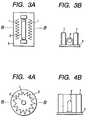
- Fig. 3A illustrates an example of the air cleaning unit of the invention
- Fig. 3B is a cross section of Fig. 3A along line B-B.
- the air cleaning unit shown has a UV-generator 2 that is fixed on a mount 3 horizontally and a photocatalyst sheet 1 that is set upright on each side of the UV-generator 2.
- the UV-generator 2 includes those generating UV light of 400 nm or shorter wavelengths, such as a blacklight blue lamp, a fluorescent lamp, a halogen lamp, a xenon flash lamp, a mercury lamp, and a germicidal lamp.
- the photocatalyst sheet 1 is folded (pleated) to provide an increased surface area. An increased surface area can also be obtained by using a honeycomb structure, etc. made of the photocatalyst sheet instead of the folded photocatalyst sheet 1.
- the photocatalyst sheet 1 is set in the vicinities of a UV-generator so that it can be efficiently irradiated with ultraviolet rays emitted from the UV-generator.
- a UV lamp 2 is put upright on a mount 3
- a pleated photocatalyst sheet 1 is set upright on the mount 3 to surround the UV lamp 2.
- a reflective mirror can be set.
- the sheet Since air diffuses and passes through the voids between the photocatalyst particles and the resin binder, air comes into contact with the wide surface area of the photocatalyst particles so that deodorizable components in air can be oxidized and deodorized with the activated photocatalyst particles.
- the polytetrafluoroethylene that is a binder resin supporting the photocatalyst particles can retain its shape while enveloping the photocatalyst particles stably for a long time. Therefore, the sheet is capable of oxidatively decomposing deodorizable components in air for a prolonged period of time.
- FIGs. 5 and 6 show a side or perspective view of other examples of the air cleaning unit of the invention, in which an air-permeable photocatalyst sheet 1, which is set within the area receptive of light from an ultraviolet generator 2, is shaped into a circular cylinder, an elliptic cylinder, an arc, a whirlpool (loose roll), an umbrella, pleats, waves, a spiral, etc. and put into a case having a filter and a fan at the air inlet and outlet, respectively.
- the arrows in these figures indicate the flow of air on which the air cleaning unit is effective.
- the unit shown in Fig. 5A has two concentric cylinders formed of an air-permeable photocatalyst sheet 1 containing a UV lamp 2 in their center so that each sheet is uniformly irradiated with UV light at a fixed distance.
- This structure is suitable for a compact air cleaning unit.
- a cylindrical reflective mirror made of, e.g., an aluminum plate, the outer side of each sheet can be made use of for air cleaning.
- the structure is effective for both an air flow parallel to the UV lamp and an air flow perpendicular to the lamp.
- the unit shown in Fig. 5B has an air-permeable photocatalyst sheet 1 shaped into an elliptic cylinder containing a U-shaped UV lamp or two parallel UV lamps, the focuses of the ellipse agreeing with the axes of the lamp(s).
- This structure is practical for a compact air cleaning unit.
- the outer side of the sheet 1 can be made use of for air cleaning by surrounding the cylinder by a cylindrical reflective mirror made of, e.g., an aluminum plate.
- the structure is effective on a parallel and a perpendicular air flow to the UV lamp.
- the U-shaped UV lamp being fixed at one end of the cylindrical sheet, is advantageous for exchange and cleaning of the photocatalyst sheet.
- the unit shown in Fig. 5C comprises a reflective plate 31, a UV lamp 2 fitted on the reflective plate 31, and two air-permeable photocatalyst sheets 1 arched over the UV lamp 2 at different curvatures.
- the unit shown in Fig. 5D has an air-permeable photocatalyst sheet 1 rolled up loosely around a UV lamp 2. According to this structure, practically the same performance as is exhibited by the structure shown in Fig. 5A can be obtained by using a single sheet.
- the unit shown in Fig. 6A comprises a plurality of air-permeable photocatalyst sheets 1 each shaped into an umbrella and fitted around the UV lamp 2. An air flow parallel to the lamp can be cleaned through multiple stages.
- the unit shown in Fig. 6B has an air-permeable photocatalyst sheet 1 folded into pleats and set on an UV lamp 2 to make a planar structure, which can be used in combination with sunlight.
- a reflective plate may be provided in the same manner as in Fig. 5C.
- the unit shown in Fig. 6C has a corrugated air-permeable photocatalyst sheet 1 set on a UV lamp 2. Being planar, the structure can be used in combination with sunlight similarly to the unit of Fig. 6B.
- a reflective plate may be provided in the same manner as in Fig. 5C.
- the unit shown in Fig. 6D has an air-permeable photocatalyst sheet 1 shaped into spiral stairs having a UV lamp 2 in the axis of the spiral.
- An air flow parallel to the lamp can be cleaned through multiple stages.
- the air cleaning unit according to the present invention is suited for removal or reduction of bad odors such as the odor of tobacco, harmful gases such as NO x and SO x , volatile organic compounds (generated from new houses) and microorganisms in a living space or a working environment.
- the air cleaning unit of the invention achieves high efficiency in air cleaning because of the continuous void structure of the photocatalyst layer.
- the units shown in Figs. 5 and 6 having an appropriately shaped air-permeable photocatalyst sheet offer the following advantages. (1) The air-permeable photocatalyst sheet is shaped to provide a structure in which air is brought into contact with the photocatalyst many times while passing through the unit. (2) Air is agitated while passing through the mesh of the air-permeable photocatalyst sheet.
- the back side of the air-permeable photocatalyst sheet opposite to the side facing an ultraviolet generator is activated by the reflected light so that the air having passed through the sheet is again treated by the back side of the sheet.
- the structure copes with either of two air flow directions, it has freedom of design for setting an ultraviolet generator to achieve high efficiency in air cleaning.
- the freedom of design combined with the simplicity of shaping the photocatalyst sheet provides a compact and inexpensive air cleaning means.
- a sheet of 60 ⁇ m thick aluminum foil was dip coated with an aqueous dispersion of polytetrafluoroethylene powder (particle size: 0.3 ⁇ m; specific gravity: 2.20) containing 40 wt% of titanium oxide particles (particle size: 7 nm; specific gravity: 3.84), dried at 100°C, and baked at 390°C for 2 minutes to obtain a photocatalyst sheet comprising a photocatalyst layer having a thickness of 7 ⁇ m and a void volume of 12.2%.
- a 10 cm wide and 100 cm long piece was cut out of the photocatalyst sheet and pleated to have an apparent size of 10 cm x 10 cm.
- the pleated piece was set on each side of a black blue light (4W; tube length: 11.5 cm) at a distance of 3 cm from the light to prepare an air cleaning unit.
- the resulting air cleaning unit was placed in the toilet room (floor space: about 0.9 m x 1.8 m) of 8 ordinary Japanese houses where bad odor was always perceived.
- the bad odor was removed in 6 toilet rooms after one day from the placement and in 2 toilet rooms after two days from the placement.
- a photocatalyst sheet was prepared in the same manner as in Example 1, except for replacing the aluminum foil with carbon fiber felt having a thickness of 0.6 mm and a basis weight of 30 g/m 2 .
- a commercially available deodorant sheet mainly comprising copper carboxymethylcellulose (Clean Sky, produced by Kohjin Co., Ltd.) was laminated on the photocatalyst sheet.
- a 10 cm wide and 100 cm long piece was cut out of the laminated sheet and pleated to have an apparent size of 10 cm x 10 cm.
- a hook was attached to each end of the pleated piece.
- An air cleaning unit was assembled using the pleated piece in the same manner as in Example 1 and placed in a chemicals storage (floor space: about 0.9 m x 1.8 m) which always had an unpleasant odor. The unpleasant odor was gotten rid of after 5 hours from the placement.
- An air cleaning unit was prepared in the same manner as in Example 1, except for replacing polytetrafluoroethylene with a perfluoroalkyl vinyl ether-tetrafluoroethylene copolymer having a melt viscosity of 10 4 poise.
- the void volume of the photocatalyst layer was 1%.
- the air cleaning unit was tested in toilet rooms in the same manner as in Example 1 but failed to carry out satisfactory deodorizing.
- An air cleaning unit was prepared in the same manner as in Example 1, except that the photocatalyst layer of the photocatalyst sheet had a void volume of 3.1% and a thickness of 7 ⁇ m.
- the deodorizing efficiency achieved was lower than that of Example 1 but more satisfactory than in Comparative Example 1.
- the inferiority in deodorizing performance of the air cleaning unit of Comparative Example 1 to those of Examples 1 to 3 is assumed to be because the perfluoroalkyl vinyl ether-tetrafluoroethylene copolymer is fused to the photocatalyst particles on baking to cover most of the surface area of the photocatalyst particles and also because the copolymer hardly retains its powdered form while being baked due to its low melt viscosity, leaving little vacancy among sintered particles.
- Glass fiber cloth of plain weave (fiber thickness: 0.5 mm; mesh size: 2.5 mm x 2.5 mm; porosity: about 30%) was dip coated with the same dispersion as used in Example 1, dried at 110°C for 60 seconds to remove the water content, and baked at 370°C for 100 seconds to obtain an air-permeable photocatalyst sheet having a thickness of 0.55 mm.
- the amount of titanium oxide particles adhered to the cloth was 90 g/m 2 .
- An air-permeable photocatalyst sheet was prepared in the same manner as in Example 4, except for replacing polytetrafluoroethylene of the dispersion with a perfluoroalkyl vinyl ether-tetrafluoroethylene copolymer.
- a 200 mm wide and 300 mm long piece was cut out of each of the air-permeable photocatalyst sheets obtained in Example 4 and Comparative Example 2.
- a blacklight (10 W) was put in a 2 m 3 -volume closed container, and the cut piece of the sheet was curved into an arch and set over the blacklight at a distance of about 10 cm to make an air cleaning unit.
- the container was filled with acetaldehyde in a concentration of 10 ppm, and the blacklight was turned on.
- the UV intensity on the sheet was 1 mW/cm 2 .
- the aldehyde concentration in the container was measured by gas chromatography. As a result, the concentration in the container having the air cleaning unit of Example 4 was found reduced to 3 ppm, whereas that in the container having the unit of Comparative Example 2 was as high as about 3 times that of Example 4.
Applications Claiming Priority (2)
| Application Number | Priority Date | Filing Date | Title |
|---|---|---|---|
| JP10234958A JPH11188085A (ja) | 1997-10-23 | 1998-08-05 | 空気浄化用ユニット |
| JP23495898 | 1998-08-05 |
Publications (2)
| Publication Number | Publication Date |
|---|---|
| EP0978690A2 true EP0978690A2 (fr) | 2000-02-09 |
| EP0978690A3 EP0978690A3 (fr) | 2002-06-05 |
Family
ID=16978931
Family Applications (1)
| Application Number | Title | Priority Date | Filing Date |
|---|---|---|---|
| EP99107320A Withdrawn EP0978690A3 (fr) | 1998-08-05 | 1999-04-20 | Dispositif de purification d'air |
Country Status (2)
| Country | Link |
|---|---|
| EP (1) | EP0978690A3 (fr) |
| KR (1) | KR20000016856A (fr) |
Cited By (21)
| Publication number | Priority date | Publication date | Assignee | Title |
|---|---|---|---|---|
| WO2002073094A1 (fr) * | 2001-02-19 | 2002-09-19 | Oy Lifa Iaq Ltd. | Systeme et procede de filtrage pour un systeme de climatisation |
| EP1371408A1 (fr) * | 2000-11-27 | 2003-12-17 | Toyo ELement Industry Co., Ltd. | Purificateur d'air a economie d'energie |
| EP1450865A1 (fr) * | 2001-11-02 | 2004-09-01 | RemoteLight, Inc. | Dispositif et procede de desinfection de l'air par rayons uv |
| WO2006010993A1 (fr) * | 2004-07-19 | 2006-02-02 | Buxair N.V. | Gel et appareil pour le nettoyage et la desodorisation de fluides |
| WO2006061518A1 (fr) * | 2004-12-09 | 2006-06-15 | Centre National De La Recherche Scientifique (C.N.R.S.) | Inactivation d'agents biologiques disperses en milieu gazeux par un semi-conducteur photoactive |
| FR2892951A1 (fr) * | 2005-11-10 | 2007-05-11 | Alcion Environnement Sarl | Dispositif de traitement d'un gaz par photocatalyse |
| EP1790910A2 (fr) * | 2005-11-24 | 2007-05-30 | Electrolux Home Products Corporation N.V. | Dispositif catalyseur pour appareil ménager |
| EP1790410A1 (fr) | 2005-11-25 | 2007-05-30 | Buxair N.V. | Dispositif pour la purification et la desodorisation de fluides |
| WO2008024174A1 (fr) * | 2006-08-22 | 2008-02-28 | Northrock Distribution, Inc. | Photocatalyseur, procédés de desodorisation, et procédés permettant de fabriquer un système désodorisant |
| FR2914559A1 (fr) * | 2007-04-05 | 2008-10-10 | Marie-Charlotte Bernard | Procede de purification d'air et epurateur d'air convenant a sa mise en oeuvre |
| WO2009021108A1 (fr) * | 2007-08-07 | 2009-02-12 | Lee Antimicrobial Solutions Llc | Procédé et dispositif de traitement de l'air par ultraviolets |
| FR2923162A1 (fr) * | 2007-11-02 | 2009-05-08 | Philippe Roux | Secheur avec photo catalyse |
| EP2160207A1 (fr) * | 2007-05-17 | 2010-03-10 | Garfield Industries, Inc. | Système et procédé de filtration à air d'oxydation photocatalytique utilisant un substrat sur lequel est revêtue une poudre de particules de photocatalyseur |
| EP2181720A1 (fr) * | 2008-11-04 | 2010-05-05 | Techno-Alpes-Ing | Dispositif de décontamination d'air |
| WO2010093796A1 (fr) * | 2009-02-13 | 2010-08-19 | Lee Antimicorbial Solutions Llc | Procédé et dispositif de traitement de l'air par uv |
| FR2942965A1 (fr) * | 2009-03-16 | 2010-09-17 | Biowind | Nouveau dispositif pour le traitement de l'air |
| ITLO20090001A1 (it) * | 2009-04-16 | 2010-10-17 | Walter Navarrini | Fotocatalizzatori autopulenti a base di ossido di titanio e metodo per la loro produzione |
| USD744627S1 (en) | 2014-07-23 | 2015-12-01 | Lee Antimicrobial Solutions, Llc | Air-permeable substrate structure |
| USD814006S1 (en) | 2014-07-18 | 2018-03-27 | Synexis Llc | Device for producing non-hydrated purified hydrogen peroxide gas |
| CN108283937A (zh) * | 2018-03-12 | 2018-07-17 | 南京科技职业学院 | 一种实验室废气处理方法与装置 |
| US11629872B2 (en) | 2021-04-12 | 2023-04-18 | NQ Industries, Inc. | Single pass kill air purifier system and process of operation |
Families Citing this family (3)
| Publication number | Priority date | Publication date | Assignee | Title |
|---|---|---|---|---|
| JP2001299120A (ja) * | 2000-04-26 | 2001-10-30 | Nikko Planning Kk | 動物飼育用敷材 |
| WO2018194236A1 (fr) * | 2017-04-20 | 2018-10-25 | 유버 주식회사 | Dispositif de purification d'environnement |
| KR102019949B1 (ko) * | 2018-12-10 | 2019-11-04 | 유버 주식회사 | 환경 정화 장치 |
Citations (5)
| Publication number | Priority date | Publication date | Assignee | Title |
|---|---|---|---|---|
| JPH03106420A (ja) | 1989-09-20 | 1991-05-07 | Matsushita Electric Ind Co Ltd | 光触媒による脱臭方法 |
| JPH0735373A (ja) | 1993-07-22 | 1995-02-07 | Japan Storage Battery Co Ltd | 空調システム |
| JPH07171408A (ja) | 1993-06-28 | 1995-07-11 | Ishihara Sangyo Kaisha Ltd | 光触媒体およびその製造方法 |
| JPH07251028A (ja) | 1994-03-15 | 1995-10-03 | Mitsubishi Electric Corp | 煙草臭消臭装置 |
| JPH07284523A (ja) | 1994-04-19 | 1995-10-31 | Shoji Hirayama | 空気調和装置 |
Family Cites Families (7)
| Publication number | Priority date | Publication date | Assignee | Title |
|---|---|---|---|---|
| US5891402A (en) * | 1994-03-02 | 1999-04-06 | W. L. Gore & Associates, Inc. | Catalyst retaining apparatus and use in an ozone filter |
| CA2150320A1 (fr) * | 1995-05-26 | 1996-11-27 | Bimsara Disanayaka | Epurateur d'air actionne par uv |
| TR199800400T1 (xx) * | 1995-09-06 | 1998-05-21 | Universal Air Technology, Inc | Fotokatalitik hava dezenfeksiyonu. |
| JPH09234375A (ja) * | 1996-03-01 | 1997-09-09 | Mitsubishi Paper Mills Ltd | 光反応性有害物除去材 |
| JPH09256217A (ja) * | 1996-03-25 | 1997-09-30 | Nitto Denko Corp | ポリテトラフルオロエチレン繊維およびその製造方法 |
| JP3863599B2 (ja) * | 1996-08-06 | 2006-12-27 | 株式会社ティオテクノ | アモルファス型過酸化チタンのコーティング方法 |
| KR20000069242A (ko) * | 1996-12-13 | 2000-11-25 | 이노우에 노리유끼 | 불소수지 섬유상 재료 및 이것을 사용한 소취항균포 |
-
1999
- 1999-04-20 KR KR1019990013945A patent/KR20000016856A/ko not_active Application Discontinuation
- 1999-04-20 EP EP99107320A patent/EP0978690A3/fr not_active Withdrawn
Patent Citations (5)
| Publication number | Priority date | Publication date | Assignee | Title |
|---|---|---|---|---|
| JPH03106420A (ja) | 1989-09-20 | 1991-05-07 | Matsushita Electric Ind Co Ltd | 光触媒による脱臭方法 |
| JPH07171408A (ja) | 1993-06-28 | 1995-07-11 | Ishihara Sangyo Kaisha Ltd | 光触媒体およびその製造方法 |
| JPH0735373A (ja) | 1993-07-22 | 1995-02-07 | Japan Storage Battery Co Ltd | 空調システム |
| JPH07251028A (ja) | 1994-03-15 | 1995-10-03 | Mitsubishi Electric Corp | 煙草臭消臭装置 |
| JPH07284523A (ja) | 1994-04-19 | 1995-10-31 | Shoji Hirayama | 空気調和装置 |
Cited By (40)
| Publication number | Priority date | Publication date | Assignee | Title |
|---|---|---|---|---|
| EP1371408A1 (fr) * | 2000-11-27 | 2003-12-17 | Toyo ELement Industry Co., Ltd. | Purificateur d'air a economie d'energie |
| EP1371408A4 (fr) * | 2000-11-27 | 2005-08-03 | Toyo Element Kogyo | Purificateur d'air a economie d'energie |
| WO2002073094A1 (fr) * | 2001-02-19 | 2002-09-19 | Oy Lifa Iaq Ltd. | Systeme et procede de filtrage pour un systeme de climatisation |
| GB2390673A (en) * | 2001-02-19 | 2004-01-14 | Lifa Iaq Ltd Oy | Filtration arrangement and method for an air-conditioning system |
| GB2390673B (en) * | 2001-02-19 | 2005-06-01 | Lifa Iaq Ltd Oy | Two-stage filtration system and method for an air-conditioning system |
| EP1450865A1 (fr) * | 2001-11-02 | 2004-09-01 | RemoteLight, Inc. | Dispositif et procede de desinfection de l'air par rayons uv |
| EP1450865A4 (fr) * | 2001-11-02 | 2006-02-01 | Remotelight Inc | Dispositif et procede de desinfection de l'air par rayons uv |
| WO2006010993A1 (fr) * | 2004-07-19 | 2006-02-02 | Buxair N.V. | Gel et appareil pour le nettoyage et la desodorisation de fluides |
| WO2006061518A1 (fr) * | 2004-12-09 | 2006-06-15 | Centre National De La Recherche Scientifique (C.N.R.S.) | Inactivation d'agents biologiques disperses en milieu gazeux par un semi-conducteur photoactive |
| FR2879104A1 (fr) * | 2004-12-09 | 2006-06-16 | Centre Nat Rech Scient | Inactivation d'agents biologiques disperses en milieu gazeux par un semi-conducteur photoactive |
| FR2892951A1 (fr) * | 2005-11-10 | 2007-05-11 | Alcion Environnement Sarl | Dispositif de traitement d'un gaz par photocatalyse |
| EP1790910A2 (fr) * | 2005-11-24 | 2007-05-30 | Electrolux Home Products Corporation N.V. | Dispositif catalyseur pour appareil ménager |
| EP1790910A3 (fr) * | 2005-11-24 | 2007-07-11 | Electrolux Home Products Corporation N.V. | Dispositif catalyseur pour appareil ménager |
| EP1790410A1 (fr) | 2005-11-25 | 2007-05-30 | Buxair N.V. | Dispositif pour la purification et la desodorisation de fluides |
| WO2008024174A1 (fr) * | 2006-08-22 | 2008-02-28 | Northrock Distribution, Inc. | Photocatalyseur, procédés de desodorisation, et procédés permettant de fabriquer un système désodorisant |
| US7914733B2 (en) | 2006-08-22 | 2011-03-29 | Northrock Distribution, Inc. | Photocatalyst, methods for deodorizing, and methods for making a deodorizer system |
| FR2914559A1 (fr) * | 2007-04-05 | 2008-10-10 | Marie-Charlotte Bernard | Procede de purification d'air et epurateur d'air convenant a sa mise en oeuvre |
| WO2008122871A2 (fr) * | 2007-04-05 | 2008-10-16 | Marie-Charlotte Bernard | Procede de purification d'air et appareil epurateur d'air pour sa mise en oeuvre |
| WO2008122871A3 (fr) * | 2007-04-05 | 2009-03-05 | Marie-Charlotte Bernard | Procede de purification d'air et appareil epurateur d'air pour sa mise en oeuvre |
| EP2160207A1 (fr) * | 2007-05-17 | 2010-03-10 | Garfield Industries, Inc. | Système et procédé de filtration à air d'oxydation photocatalytique utilisant un substrat sur lequel est revêtue une poudre de particules de photocatalyseur |
| US8691144B2 (en) | 2007-05-17 | 2014-04-08 | Garfield Industries, Inc. | System and method for photocatalytic oxidation air filtration using a substrate with photocatalyst particles powder coated thereon |
| EP2160207B1 (fr) * | 2007-05-17 | 2014-11-19 | Garfield Industries, Inc. | Système et procédé de filtration à air d'oxydation photocatalytique utilisant un substrat sur lequel est revêtue une poudre de particules de photocatalyseur |
| WO2009021108A1 (fr) * | 2007-08-07 | 2009-02-12 | Lee Antimicrobial Solutions Llc | Procédé et dispositif de traitement de l'air par ultraviolets |
| US10188766B2 (en) | 2007-08-07 | 2019-01-29 | Synexis Llc | Purified hydrogen peroxide gas microbial control methods and devices |
| US8168122B2 (en) | 2007-08-07 | 2012-05-01 | Lee Antimicrobial Solutions Llc | Purified hydrogen peroxide gas microbial control methods and devices |
| US8685329B2 (en) | 2007-08-07 | 2014-04-01 | Lee Antimicrobial Solutions Llc | Purified hydrogen peroxide gas microbial control methods and devices |
| US9034255B2 (en) | 2007-08-07 | 2015-05-19 | Lee Antimicrobial Solutions Llc | Purified hydrogen peroxide gas microbial control methods and devices |
| US11207436B2 (en) | 2007-08-07 | 2021-12-28 | Synexis Llc | Purified hydrogen peroxide gas microbial control methods and devices |
| US9370592B2 (en) | 2007-08-07 | 2016-06-21 | Lee Antimicrobial Solutions Llc | Purified hydrogen peroxide gas microbial control methods and devices |
| US10940223B2 (en) | 2007-08-07 | 2021-03-09 | Synexis Llc | Purified hydrogen peroxide gas microbial control methods and devices |
| FR2923162A1 (fr) * | 2007-11-02 | 2009-05-08 | Philippe Roux | Secheur avec photo catalyse |
| FR2937871A1 (fr) * | 2008-11-04 | 2010-05-07 | Techno Alpes Ing | Dispositif de decontamination d'air |
| EP2181720A1 (fr) * | 2008-11-04 | 2010-05-05 | Techno-Alpes-Ing | Dispositif de décontamination d'air |
| WO2010093796A1 (fr) * | 2009-02-13 | 2010-08-19 | Lee Antimicorbial Solutions Llc | Procédé et dispositif de traitement de l'air par uv |
| FR2942965A1 (fr) * | 2009-03-16 | 2010-09-17 | Biowind | Nouveau dispositif pour le traitement de l'air |
| ITLO20090001A1 (it) * | 2009-04-16 | 2010-10-17 | Walter Navarrini | Fotocatalizzatori autopulenti a base di ossido di titanio e metodo per la loro produzione |
| USD814006S1 (en) | 2014-07-18 | 2018-03-27 | Synexis Llc | Device for producing non-hydrated purified hydrogen peroxide gas |
| USD744627S1 (en) | 2014-07-23 | 2015-12-01 | Lee Antimicrobial Solutions, Llc | Air-permeable substrate structure |
| CN108283937A (zh) * | 2018-03-12 | 2018-07-17 | 南京科技职业学院 | 一种实验室废气处理方法与装置 |
| US11629872B2 (en) | 2021-04-12 | 2023-04-18 | NQ Industries, Inc. | Single pass kill air purifier system and process of operation |
Also Published As
| Publication number | Publication date |
|---|---|
| KR20000016856A (ko) | 2000-03-25 |
| EP0978690A3 (fr) | 2002-06-05 |
Similar Documents
| Publication | Publication Date | Title |
|---|---|---|
| EP0978690A2 (fr) | Dispositif de purification d'air | |
| US8709341B2 (en) | System for purifying air through germicidal irradiation and method of manufacture | |
| KR19990037362A (ko) | 광촉매-지지체 및 광촉매 장치 | |
| EP0993859A1 (fr) | Dispositif de filtre photocatalytique tridimensionnel | |
| US11629872B2 (en) | Single pass kill air purifier system and process of operation | |
| US20040007453A1 (en) | Photocatalytic air purifier | |
| JP5262219B2 (ja) | 光触媒脱臭機 | |
| JP3725925B2 (ja) | メッシュシート、脱臭エレメントおよび脱臭装置 | |
| JPH11207149A (ja) | 金属担持光触媒型の空気清浄器 | |
| JPH11188085A (ja) | 空気浄化用ユニット | |
| JP2000107276A (ja) | 空気浄化装置 | |
| JP2000051712A (ja) | 光触媒体 | |
| JPH11114048A (ja) | 空気浄化装置 | |
| JPH01231926A (ja) | 空気清浄機 | |
| JPH09135891A (ja) | 脱臭装置 | |
| JPH11276558A (ja) | 流体の浄化装置及びこの装置に用いる光触媒体 | |
| JP2002272824A (ja) | 空気清浄機 | |
| JPH11216365A (ja) | 光触媒体、光触媒装置及び収容装置 | |
| JP3963541B2 (ja) | 太陽光照射式空気清浄用シート及び空気の浄化方法 | |
| JP2000093808A (ja) | 光触媒シ−ト及び光触媒シ−ト構造体 | |
| JP4125819B2 (ja) | 光触媒体 | |
| CN216080241U (zh) | 具有高效光催化“记忆”效应的空气净化器过滤组件 | |
| JP2000176294A (ja) | 通気性光触媒構造体及びその使用方法 | |
| US20230400199A1 (en) | Insert device for an air conditioning installation and air conditioning installation with insert device | |
| JP2000033270A (ja) | 光触媒体 |
Legal Events
| Date | Code | Title | Description |
|---|---|---|---|
| PUAI | Public reference made under article 153(3) epc to a published international application that has entered the european phase |
Free format text: ORIGINAL CODE: 0009012 |
|
| AK | Designated contracting states |
Kind code of ref document: A2 Designated state(s): AT BE CH CY DE DK ES FI FR GB GR IE IT LI LU MC NL PT SE |
|
| AX | Request for extension of the european patent |
Free format text: AL;LT;LV;MK;RO;SI |
|
| PUAL | Search report despatched |
Free format text: ORIGINAL CODE: 0009013 |
|
| AK | Designated contracting states |
Kind code of ref document: A3 Designated state(s): AT BE CH CY DE DK ES FI FR GB GR IE IT LI LU MC NL PT SE |
|
| AX | Request for extension of the european patent |
Free format text: AL;LT;LV;MK;RO;SI |
|
| AKX | Designation fees paid | ||
| STAA | Information on the status of an ep patent application or granted ep patent |
Free format text: STATUS: THE APPLICATION IS DEEMED TO BE WITHDRAWN |
|
| REG | Reference to a national code |
Ref country code: DE Ref legal event code: 8566 |
|
| 18D | Application deemed to be withdrawn |
Effective date: 20021031 |