EP0976165B1 - Actionneur piezoelectrique a nouveau mode de contact et son procede de fabrication - Google Patents
Actionneur piezoelectrique a nouveau mode de contact et son procede de fabrication Download PDFInfo
- Publication number
- EP0976165B1 EP0976165B1 EP98928099A EP98928099A EP0976165B1 EP 0976165 B1 EP0976165 B1 EP 0976165B1 EP 98928099 A EP98928099 A EP 98928099A EP 98928099 A EP98928099 A EP 98928099A EP 0976165 B1 EP0976165 B1 EP 0976165B1
- Authority
- EP
- European Patent Office
- Prior art keywords
- stack
- contact
- actuator
- contact lugs
- contact lug
- Prior art date
- Legal status (The legal status is an assumption and is not a legal conclusion. Google has not performed a legal analysis and makes no representation as to the accuracy of the status listed.)
- Expired - Lifetime
Links
Images
Classifications
-
- H—ELECTRICITY
- H10—SEMICONDUCTOR DEVICES; ELECTRIC SOLID-STATE DEVICES NOT OTHERWISE PROVIDED FOR
- H10N—ELECTRIC SOLID-STATE DEVICES NOT OTHERWISE PROVIDED FOR
- H10N30/00—Piezoelectric or electrostrictive devices
- H10N30/01—Manufacture or treatment
- H10N30/06—Forming electrodes or interconnections, e.g. leads or terminals
-
- H—ELECTRICITY
- H10—SEMICONDUCTOR DEVICES; ELECTRIC SOLID-STATE DEVICES NOT OTHERWISE PROVIDED FOR
- H10N—ELECTRIC SOLID-STATE DEVICES NOT OTHERWISE PROVIDED FOR
- H10N30/00—Piezoelectric or electrostrictive devices
- H10N30/50—Piezoelectric or electrostrictive devices having a stacked or multilayer structure
-
- H—ELECTRICITY
- H10—SEMICONDUCTOR DEVICES; ELECTRIC SOLID-STATE DEVICES NOT OTHERWISE PROVIDED FOR
- H10N—ELECTRIC SOLID-STATE DEVICES NOT OTHERWISE PROVIDED FOR
- H10N30/00—Piezoelectric or electrostrictive devices
- H10N30/80—Constructional details
- H10N30/87—Electrodes or interconnections, e.g. leads or terminals
- H10N30/875—Further connection or lead arrangements, e.g. flexible wiring boards, terminal pins
Definitions
- Piezo actuators usually consist of a plurality of piezo elements arranged in a stack. Each of these elements in turn consists of a piezoceramic layer, which is provided on both sides with metallic electrodes. If a voltage is applied to these electrodes, the piezoceramic layer reacts with a lattice distortion, which leads along a main axis to a usable longitudinal expansion. Since this in turn is less than two parts per thousand of the layer thickness along the main axis, a correspondingly higher layer thickness of active piezoceramic must be provided in order to achieve a desired absolute linear expansion. With increasing layer thickness of the piezoceramic layer within a piezo element, however, the voltage required to respond to the piezo element also increases. In order to obtain these within manageable limits, multi-layer actuators are produced in which the thicknesses of piezo individual elements are usually between 20 and 200 ⁇ m.
- piezoelectric actuators in multilayer construction therefore consist of a total of up to a few hundred individual layers.
- piezoceramic green sheets are arranged alternately with electrode material into a stack and laminated together to a monolithic composite of up to about 5 mm in height and sintered. Larger actuators with greater absolute deflection can be obtained, for example, by gluing several such stacks. Sufficient stiffness, especially when high forces have to be transmitted with the piezoelectric actuator, possess only piezo actuators in fully monolithic multilayer construction.
- each second electrode layer For electrical contacting of such piezo actuators in multilayer construction, for example, metallization on the outside of the piezoelectric actuator or in a bore mounted in the center of the individual actuators.
- each second electrode layer For example, to bond each second electrode layer to one of the metallization strips, it must be isolated from the intervening electrode layers. This is achieved in a simple manner by virtue of the fact that every second electrode layer in the region of the one metallization strip has a recess in which it is not guided to the metallization strip. The remaining electrode layers then have the recesses in the region of the second metallization strip in order to allow contact with alternating polarity. Wires for the electrical connection are soldered to the metallization strips.
- Such an actuator is known from EP-A-0 584 842.
- Piezoelectric actuators whose alternating contacting takes place via recesses of the electrode layers, are piezoelectrically inactive in the contacting region, since no electrical field can build up there through the respective one missing electrode. This has both in the polarization and during operation of the piezoelectric actuator with the result that build up in this piezoelectrically inactive contacting region mechanical stresses that can lead to cracks in the inactive areas and thus also on the metallization parallel to the electrode layers. This can lead to complete severing of the metallization and has the consequence that when punctiform voltage supply from the outside of the metallization a part of the piezoelectric actuator is suspended from the power supply and thus inactive.
- the number of cracks depends on the total height of the actuator as well as the strength of the internal electrode / piezoceramic interface and can continue to increase in continuous operation under changing load conditions. Since a dynamic change of the cracks or the crack openings also results during dynamic operation, the metallization strips are thereby further damaged during the operation of the actuator.
- Object of the present invention is to provide a ceramic actuator including manufacturing process, the safe and has good manageable electrical contact, which shows an increased stability against cracking.
- the actuator according to the invention may have a conventional and preferably monolithic structure.
- Stack-like piezoelectric ceramic layers and electrode layers are arranged one above the other alternately and preferably sintered together.
- at least two electrically conductive contact lugs are provided on the outside of the stack for alternating contacting of the electrode layers. These are connected by an edge to the electrode layers and extend over the entire height of the electrically active region of the stack. Laterally of the connected edge, they have a projecting area and in the area of the outer edge facing away from the stack there is an electrical connection element protruding laterally or stackwise in height.
- the contact lug With the contact lug, it is possible to electrically bridge any cracks occurring in the metallization during operation of the actuator. If the projecting area is chosen to be sufficiently wide, the cracks will run out within the contact lug or within the projecting area. Thus, all the individual elements of the actuator remain electrically functional, even if cracks occur at the metallizations.
- the actuator according to the invention therefore shows no performance losses during operation.
- the connecting element on the outer edge allows easy connection of the contact lug to an external power or voltage supply. It surmounted the contact lug on the side or the stack in height and is so even when installing the Stack in a housing still easily accessible, allowing a simple power connection.
- the connecting element is made of the material of the contact lug, or an integral part of the contact lug.
- This comprises at least one electrically conductive layer.
- it consists of a composite material with at least one plastic film and at least one metallic film or layer.
- Such a composite material has a high flexibility with high tear resistance and elasticity.
- the connecting element represents an extension of the edge facing away from the stack outer edge of the contact lug up or an extension of the upper edge to the outside or to the side.
- the connection element also serves to facilitate handling of the contact lug and provided with the contact lug actuator especially during installation in a housing.
- the connection elements can serve as a guide.
- connection element is therefore designed so that it represents an additional mechanical reinforcement of the outer edge of the contact lug.
- the connecting element is designed as a metallic pin. This can be soldered to the contact lug or on its metallic layer or otherwise electrically conductively attached. The terminal pin may extend over the entire outer edge or be connected only to a part of the edge. With such a mechanically reinforcing connecting element, the guidance or handling of the contact lug attached to the stack is facilitated.
- the connecting element formed as a connecting pin may additionally be part of an electrical plug connection. This allows a very simple connection to an electrical voltage source.
- the actuator preferably has a pressure plate on an end face of the stack. This has openings through which the connecting elements are inserted or passed. In mechanically reinforced connection elements, the openings are designed so that a guide and holding the connection elements is ensured.
- the pressure plate has a recess for fixing the stack therein. This allows for safe installation of the stack, including the contact lug, into an actuator housing, with the stack securely aligned and centered.
- actuators may be integrated in the pressure plate, such as force sensors, temperature sensors, other sensors (e.g., Hall sensors), or a second actuator as an adjusting element for stiffness, thermal expansion compensation and zero point adjustment.
- the stack is preferably cast in a plastic sleeve or molded with a plastic. Elastomers based on silicone resin are particularly suitable for this purpose.
- the installation in the plastic sleeve can be done with the help of the pressure plate, with a simple guidance and fixation of stack, contact lug and connection element is achieved.
- the other already mentioned above and the actuator completing elements can be incorporated into the enclosure when pouring or encapsulating with plastic, unless they are otherwise installed and, for example, in the pressure plate.
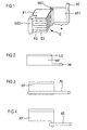
- FIG. 1 shows a detail of an actuator according to the invention, in which for the sake of clarity, only one contact lug KF is shown.
- Core of the actuator is the stack S, which is constructed of alternating electrode layers E1, E2 and ceramic layers KS.
- the actuator shown here with square base surface is provided at opposite corners with metallization MS, which are connected due to the geometric configuration of the electrodes E with each second electrode, so that a parallel interconnection of all individual actuator elements is possible.
- On the first metallization strip MS1 a contact lug KF1 is attached over its entire height with an edge so that a part or the rest of the contact lug protrudes laterally on the stack.
- a connecting element AE is arranged, which projects beyond the stack in height or laterally.
- the width of the protruding portion a is sufficiently selected, cracks occurring in the metallization during the operation or polarity of the actuator, and in particular in the metallization strips MS expire within the contact lug KF, the extent to which the connecting element AE the contact lug KF or the stack S in height or laterally surmounted by the further construction of the actuator, the housing or the other electrical connections.
- FIG. 2 shows the simplest embodiment of the invention, in which the contact lug and connecting element are prefabricated from an electrically conductive foil, for example a copper-clad plastic foil.
- the contact lug In the region of its inner edge, the contact lug has a narrow solder layer LS, by means of which a simple soldering of the contact foil to the metallization strips MS is possible. With the help of the solder layer, the contact lug can alternatively be attached directly to the stack or to the electrode layers even without metallization strips.
- a preferred and gentle method of attachment is laser beam soldering which produces only minimal thermal loading of the thermally sensitive multilayer structure.
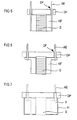
- Figure 3 shows a further embodiment of the contact lug KF, which in turn is formed as a film with at least one electrically conductive layer.
- the connecting element AE is formed here as a metallic pin, which is electrically connected to the contact lug KF in the region of an outer edge and soldered, for example.
- the pin has, for example, a round cross-section.
- Figure 4 shows another possible embodiment of the contact lug KF, in which the connecting element AE represents a lateral extension of the contact lug. It can be connected as shown in the figure with a metallic pin and thus form a combined connection element.
- the contact lug KF is prefabricated before attaching to the metallizations or directly on the stack, that is, provided with connecting elements AE and possibly the solder layer LS.
- FIG. 5 shows a partial module of the actuator, comprising the stack S provided with contact lugs KF and a pressure plate DP which has feedthroughs DF for the connection elements AE.
- the bushings DF serve to guide and hold both the connecting elements and the contact lug KF connected thereto.
- the pressure plate DP is disposed on an end face of the stack S and includes, for example, for fixing the stack one of the end surface adapted recess of approximately 50 to 100 ⁇ m depth.
- the further processing for example, the installation in an actuator housing is facilitated, as facilitated by the fixation of stack S, contact lug KF and connecting elements AE in the pressure plate DP, the alignment and centering of the actuator, which is required for optimal transmission of forces becomes.
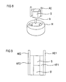
- FIG. 6 shows a modified partial module with contact lugs KF and connecting elements AE designed according to FIG.
- the connection elements in feedthroughs DF and the stack S are also fixed in a recess of the pressure plate.
- An electrically conductive connection of the connecting elements with the contact lugs is made in this embodiment after the assembly of printing plate and stack, for example by soldering.
- This embodiment has the advantage that pressure plate and connecting elements form a solid unit, which can serve as a plug contact for connection to a current / voltage source, for example at the same time.
- the sealing of the bushings can be made without regard to a mechanical or thermal load on the actuator and can be designed so very tight.
- FIG. 7 The sub-module of pressure plate, connecting elements, tabs and stack is provided for electrical passivation and mechanical protection with a sheath.
- a sleeve H is provided for this purpose, which consists for example of plastic or metal, which is adapted to the size of the sub-module and which seals with the pressure plate.
- the submodule is inserted and then potted or overmolded over a remaining free opening with plastic K, for example, a silicone elastomer.
- plastic K for example, a silicone elastomer.
- both all electrically active surfaces of the stack and the contact lugs are electrically and isolated from environmental influences, as well as a mechanically strong connection between sleeve H, pressure plate DP and stack S produced.
- the lower end face of the stack remains free, since a better force transmission is possible with the preferably ceramic end face of the stack than with the sleeve.
- the ceramic multilayer stack S Before pouring or injecting the submodule into a sleeve, it is possible to additionally passivate the electrically active surfaces of the ceramic multilayer stack S, in particular by applying an electrically insulating, sufficiently elastic plastic compound, for example once again a silicone elastomer.
- the passivation is facilitated by the holder of the contact lug on the fixed in the pressure plate connection elements.
- the passivation prevents that a short circuit between a contact lug and an electrically active surface area of the stack occurs due to the mechanical forces occurring during encapsulation or potting and acting on the contact lugs KF, which could lead to a malfunction of the actuator.
- the flexible contact lugs KF can otherwise be fixed via the connection elements AE, so that the passivation, for example by brush application, is facilitated.
- the connecting elements and optionally also the stack can be fixed in an auxiliary holder.
- the passivation of the stacking surfaces prior to assembly of said sub-module has the advantage that the contact lugs KF can now be arranged closer to the stack before further processing and, for example, also applied. This is a space-saving arrangement in a sleeve H possible.
- a stack with contact lugs resting on the side surfaces is mechanically more stable and additionally protected against mechanical damage during installation in the sleeve or in an actuator housing.
- the contact lugs it is possible to attach the contact lugs to the side surfaces of the stack and to fix there, for example, by an elastic plastic ring which is pushed over the stack together with adjacent contact lugs and connecting elements and presses contact lugs and connecting elements closely to the stack.
- Figure 8 shows a further embodiment of the invention, with a safe installation of the stack including contact lug and connecting elements in a plastic sleeve H is possible.
- the plastic sleeve is not designed as an empty hollow cylinder, but already has an inner profile, which is adapted to the geometric shape of stack, contact lug and connecting elements. After the introduction of the stack in the preformed inner profile of the sleeve H (see direction arrow b) are both stack and contact lugs and connecting elements sufficiently fixed. When now filling with plastic of the remaining spaces to the inner profile damage to the tabs or an unwanted short circuit between the contact lugs and optionally exposed electrically active surfaces of the stack is avoided.
- both the connecting elements AE and the stack S in a holder such as a pressure plate DP (not shown in Figure 8) may be fixed to allow both easier insertion of the stack in the sleeve H, as well as a one-sided to allow hermetically sealed sealing of the stack in the sleeve.
- FIG. 9 shows a further embodiment of the invention, which can be combined with all the already described representations.
- This comprises a stack of two stacked S, S 'existing multi-layer structure, in which the stack S and S' are connected by means of common contact lugs KF and thus fixed against each other.
- Mechanically reinforced connection elements AE for example metallic pins additionally stabilize the arrangement. In this way, it is possible to achieve the necessary overall height of multi-layer structure and thus of possible deflection of the actuator from technologically simpler to produce low stacks, and thereby achieve a simple and elegant connection of the two sub-stacks S, S '.
- Auxiliary support can also serve here for the early centering of several stacks on top of each other, the latter can already be arranged and aligned on a pressure plate. This simplifies the laser beam soldering of the common contact lugs KF to the stacks S and S 'and facilitates the centering of the stacks during injection molding.
Claims (17)
- Actionneur céramique, comprenant- une construction à plusieurs couches, comportant au moins une pile (S) de couches alternantes d'électrodes (E) et de céramique (KS) ;- au moins deux languettes de contact (KF) électriquement conductrices en forme de bandes et fixées latéralement sur chaque pile,caractérisé en ce- que chaque languette de contact (KF) est connectée de manière électriquement conductrice aux couches d'électrodes par une arête et comprend une partie (a) faisant latéralement saillie par rapport à cette arête ;- que chaque languette de contact comporte un élément de connexion électrique (AE) dépassant latéralement la languette de contact ou dépassant la pile en hauteur, cet élément étant disposé dans la zone de l'arête extérieure s'étendant en sens opposé de la pile, de la languette de contact respective.
- Actionneur selon la revendication 1, dans lequel l'élément de connexion (AE) comprend une broche de connexion métallique qui renforce mécaniquement l'arête extérieure de la languette de contact (KF) et qui s'étend le long de l'arête extérieure sur toute sa longueur.
- Actionneur selon la revendication 1 ou 2, dans lequel l'élément de connexion (AE) comprend un prolongement de la languette de contact sous forme de bande qui est reliée à des broches de connexion métalliques.
- Actionneur selon la revendication 2 ou 3, dans lequel une plaque de compression (DP) est disposée au-dessus d'une face frontale de la pile (S), les broches de connexion (AE) étant passées à travers la plaque et fixées dans celle-ci.
- Actionneur selon l'une des revendications 2 à 4, dans lequel les broches de connexion (AE) sont réalisées en forme de contact enfichable.
- Actionneur selon la revendication 4, dans lequel un évidement est prévu dans la plaque de compression (DP), dans lequel la pile (S) est fixée.
- Actionneur selon l'une des revendications 1 à 6, dans lequel la pile (S) et les languettes de contact (KF) sont enrobées ou coulées de tous les côtés par une matière synthétique (K) dans une enveloppe compacte en matière synthétique, et dans laquelle des éléments de connexion électriques (AE) sont sortis frontalement de l'enveloppe en matière synthétique (H).
- Actionneur selon la revendication 7, dans lequel l'enveloppe en matière synthétique est formée par un élastomère de silicone (K).
- Actionneur selon l'une des revendications 1 à 7, dans lequel plusieurs piles (S, S') sont disposées en superposition et connectées par des languettes de contact (KF) communes.
- Procédé pour la mise en contact d'un actionneur céramique ayant une construction multicouche,- dans lequel une pile (S) de couches alternantes d'électrodes et de céramique (E1, KS, E2) formant le montage multicouche est fabriquée,- dans lequel des languettes de contact (KF) sont fabriquées à partir d'une feuille comportant au moins une couche électriquement conductrice, la grandeur de ces languettes étant adaptée à la hauteur du montage multicouche, des éléments de connexion électrique (AE) étant prévus dans la zone d'une arête de la languette de contact qui dépassent latéralement la languette de contact ou dépassent en hauteur le montage multicouche,- dans lequel au moins deux languettes de contact sont fixées latéralement à la pile (S) par une de leurs arêtes, de telle façon qu'une partie (a) dépasse latéralement la pile, un contact électriquement conducteur étant réalisé vers les couches d'électrodes.
- Procédé selon la revendication 10, dans lequel la pile (S) est équipée latéralement de deux métallisations (MS) en forme de bande pour la mise en contact des couches d'électrodes, et dans lesquelles les languettes de contact sont fixées sur les métallisations en forme de bande.
- Procédé selon la revendication 10 ou 11, dans lequel la fixation est effectuée par une soudure au laser.
- Procédé selon l'une des revendications 10 à 12, dans lequel on prévoit comme éléments de connexion (AE) des broches métalliques qui sont soudées sur les languettes de contact avant la fixation des languettes de contact (KF) dans la zone de l'arête opposée à la pile.
- Procédé selon l'une des revendications 10 à 13, dans lequel la surface électriquement active de la pile (S) est recouverte, après la fixation des languettes de contact (KF), d'une couche de passivation organique électriquement isolante de telle manière qu'au moins les éléments de connexion (AE) des languettes de contact restent libres et les surfaces frontales de la pile (S) restent également libres.
- Procédé selon l'une des revendications 10 à 14, dans lequel la pile (S) est insérée, après la fixation des languettes de contact (KF), dans une douille (H) en matière synthétique et qu'elle est coulée ou enrobée en une matière synthétique (K), de telle sorte que les extrémités des éléments de connexion (AE) restent libres.
- Procédé selon la revendication 15, dans lequel une plaque de compression (DP) présentant des passages (DF) est prévue à travers laquelle les éléments de connexion (AE) sont passés, dans lequel la pile (S) est fixée dans la plaque de compression (DP) et coulée ou enrobée dans la douille en matière synthétique (H).
- Procédé selon l'une des revendications 10 à 16, dans lequel deux piles (S, S') sont disposées en superposition, équipées de languettes de contact communes (KF1, KF2) et reliées de cette manière pour former une pile double.
Applications Claiming Priority (3)
| Application Number | Priority Date | Filing Date | Title |
|---|---|---|---|
| DE19715488A DE19715488C1 (de) | 1997-04-14 | 1997-04-14 | Piezoaktor mit neuer Kontaktierung und Herstellverfahren |
| DE19715488 | 1997-04-14 | ||
| PCT/DE1998/000917 WO1998047187A1 (fr) | 1997-04-14 | 1998-03-31 | Actionneur piezoelectrique a nouveau mode de contact et son procede de fabrication |
Publications (2)
| Publication Number | Publication Date |
|---|---|
| EP0976165A1 EP0976165A1 (fr) | 2000-02-02 |
| EP0976165B1 true EP0976165B1 (fr) | 2007-01-24 |
Family
ID=7826438
Family Applications (1)
| Application Number | Title | Priority Date | Filing Date |
|---|---|---|---|
| EP98928099A Expired - Lifetime EP0976165B1 (fr) | 1997-04-14 | 1998-03-31 | Actionneur piezoelectrique a nouveau mode de contact et son procede de fabrication |
Country Status (5)
| Country | Link |
|---|---|
| US (1) | US6316863B1 (fr) |
| EP (1) | EP0976165B1 (fr) |
| JP (1) | JP4229986B2 (fr) |
| DE (2) | DE19715488C1 (fr) |
| WO (1) | WO1998047187A1 (fr) |
Families Citing this family (48)
| Publication number | Priority date | Publication date | Assignee | Title |
|---|---|---|---|---|
| DE19930585B4 (de) * | 1998-08-06 | 2017-11-09 | Epcos Ag | Piezoaktor mit verbesserter elektrischer Kontaktierung und Verwendung eines derartigen Piezoaktors |
| DE19856202A1 (de) * | 1998-12-05 | 2000-06-15 | Bosch Gmbh Robert | Piezoelektrischer Aktor |
| DE19914411A1 (de) | 1999-03-30 | 2000-10-12 | Bosch Gmbh Robert | Piezoelektrischer Aktor |
| DE19928178A1 (de) * | 1999-06-19 | 2000-08-10 | Bosch Gmbh Robert | Piezoaktor |
| DE19928189A1 (de) * | 1999-06-19 | 2001-04-19 | Bosch Gmbh Robert | Piezoaktor |
| DE19928185B4 (de) * | 1999-06-19 | 2006-05-24 | Robert Bosch Gmbh | Piezoaktor |
| DE50014127D1 (de) * | 1999-06-29 | 2007-04-19 | Siemens Ag | Piezoaktor mit einer elektrisch leitenden Mehrschichtfolie |
| DE19940346B4 (de) * | 1999-08-25 | 2018-03-22 | Continental Automotive Gmbh | Piezoaktor mit einer Anschlußvorrichtung |
| DE19945267C1 (de) * | 1999-09-21 | 2001-04-19 | Bosch Gmbh Robert | Verfahren zur Anbringung von flächigen Außenelektroden auf einem piezokeramischen Vielschichtaktor |
| US6664714B2 (en) | 2000-03-23 | 2003-12-16 | Elliptec Resonant Actuator Ag | Vibratory motors and methods of making and using same |
| US20010033125A1 (en) * | 2000-04-20 | 2001-10-25 | Tokin Corporation | Multilayer piezoelectric actuator device having a conductive member attached to an external electrode thereof |
| DE10026635B4 (de) * | 2000-05-29 | 2006-01-05 | Epcos Ag | Verfahren zum Herstellen einer Lotverbindung, elektrotechnisches Erzeugnis mit der Lotverbindung und Verwendung des elektrotechnischen Erzeugnisses |
| DE10152490A1 (de) * | 2000-11-06 | 2002-05-08 | Ceramtec Ag | Außenelektroden an piezokeramischen Vielschichtaktoren |
| DE10113744A1 (de) * | 2000-11-27 | 2002-06-20 | Hans Richter | Elektrische Anschlußanordnung für einen monolithischen Vielschicht-Piezoaktor |
| DE10201943A1 (de) * | 2001-02-15 | 2002-10-24 | Ceramtec Ag | Vielschichtaktor mit versetzt angeordneten Kontaktflächen gleich gepolter Innenelektroden für ihre Außenelektrode |
| DE50203457D1 (de) | 2001-04-30 | 2005-07-28 | Siemens Ag | Weiterkontaktierung für ein elektrisches bauteil sowie piezoelektrisches bauteil in vielschichtbauweise |
| DE10131621A1 (de) * | 2001-06-29 | 2003-01-23 | Epcos Ag | Weiterkontaktierung für ein elektrisches Bauteil sowie piezoelektrisches Bauteil in Vielschichtbauweise |
| DE10144919A1 (de) | 2001-09-12 | 2003-05-22 | Siemens Ag | Vorrichtung umfassend einen piezoelektrischen Aktor |
| DE10146704A1 (de) * | 2001-09-21 | 2003-04-10 | Elliptec Resonant Actuator Ag | Piezomotoren mit Piezoelementen, hergestellt nach dem Keramikkondensatorverfahren |
| EP1483826B1 (fr) * | 2002-02-06 | 2007-11-14 | Elliptec Resonant Actuator AG | Regulation de moteur piezo-electrique |
| DE10225408B4 (de) * | 2002-06-07 | 2004-11-25 | Epcos Ag | Piezoaktor, Verfahren zu dessen Herstellung und dessen Verwendung |
| DE10229494A1 (de) * | 2002-07-01 | 2004-01-29 | Siemens Ag | Piezoaktor sowie Verfahren zu dessen Herstellung |
| DE10250202A1 (de) * | 2002-10-28 | 2004-05-13 | Siemens Ag | Aktor mit einer Durchführungsöffnung, die bei der Umspritzung gegen eindringenden Kunststoff abgedichtet ist |
| DE10259949A1 (de) * | 2002-12-20 | 2004-07-01 | Robert Bosch Gmbh | Piezoaktor |
| DE10317148B4 (de) * | 2003-04-14 | 2020-10-01 | Robert Bosch Gmbh | Brennstoffeinspritzventil |
| DE10324044B4 (de) * | 2003-05-27 | 2006-01-12 | Siemens Ag | Dilatometer mit einer Interferometeranordnung und Verwendung des Dilatometers mit der Interferometeranordnung |
| DE10341333B4 (de) * | 2003-09-08 | 2006-06-08 | Siemens Ag | Piezoaktor und Verfahren zum Herstellen eines Piezoaktors |
| DE10349309A1 (de) * | 2003-10-23 | 2005-05-25 | Siemens Ag | Aktor mit einem Temperatursensor und Herstellungsverfahren für einen solchen Aktor |
| DE10350061A1 (de) * | 2003-10-27 | 2005-05-25 | Robert Bosch Gmbh | Aktormodul |
| DE502004006148D1 (de) * | 2003-11-12 | 2008-03-20 | Siemens Vdo Automotive Ag | Kontaktierungsmatte f r einen aktor und zugeh riges her stellungsverfahren |
| DE102004005944A1 (de) * | 2004-02-06 | 2005-09-08 | Siemens Ag | Elektrisches Anschlusselement, elektrisches Bauteil mit dem Anschlusselement und Verwendung des Bauteils |
| EP1564823B1 (fr) * | 2004-02-12 | 2006-12-20 | Siemens Aktiengesellschaft | Natte de contact pour un actionneur, aide positionnante pour telle natte et méthode relative de fabrication |
| DE102004011697A1 (de) * | 2004-03-10 | 2005-11-24 | Siemens Ag | Verfahren zur Anordnung eines Kontaktpins für ein Piezoelement sowie Hülse und Aktoreinheit |
| DE102004024123A1 (de) * | 2004-05-14 | 2005-12-08 | Siemens Ag | Kopfplattenbaugruppe für einen Aktor und Herstellungsverfahren für einen Aktor |
| DE102004028884A1 (de) * | 2004-06-15 | 2006-01-05 | Robert Bosch Gmbh | Piezoaktor |
| DE102004043525B4 (de) * | 2004-09-08 | 2011-02-24 | Epcos Ag | Piezoaktor und Verwendung des Piezoaktors |
| DE102005002980B3 (de) * | 2005-01-21 | 2006-09-07 | Siemens Ag | Monolithischer Vielschichtaktor und Verfahren zu seiner Herstellung |
| JP2006303443A (ja) * | 2005-03-24 | 2006-11-02 | Ngk Spark Plug Co Ltd | 積層型圧電素子、これを用いた燃料噴射装置、及び積層型圧電素子の製造方法 |
| DE102005044392A1 (de) * | 2005-09-16 | 2007-03-29 | Siemens Ag | Piezoaktor mit verbesserter Verbindung zwischen Aktorkörper und Kontaktstift |
| JP4936306B2 (ja) * | 2006-01-13 | 2012-05-23 | 日本碍子株式会社 | 積層型圧電素子およびその製造方法 |
| DE102007021337A1 (de) * | 2007-05-07 | 2008-11-13 | Robert Bosch Gmbh | Piezoelektrische Antriebsvorrichtung |
| JP4983405B2 (ja) * | 2007-05-30 | 2012-07-25 | 株式会社デンソー | 圧電アクチュエータ及びその製造方法 |
| DE102008003821A1 (de) * | 2008-01-10 | 2009-07-16 | Epcos Ag | Piezoelektrische Aktoreinheit |
| DE102008050539A1 (de) | 2008-10-06 | 2010-04-08 | Epcos Ag | Piezoaktor mit Außenelektrode |
| DE102009020238B4 (de) * | 2009-05-07 | 2017-10-19 | Epcos Ag | Piezoaktor mit elektrischen Kontaktierungsstiften und Verfahren zum Kontaktieren eines Piezoaktors |
| US8599826B2 (en) | 2010-04-15 | 2013-12-03 | Motorola Solutions, Inc. | Method for synchronizing direct mode time division multiple access (TDMA) transmissions |
| US20120038469A1 (en) * | 2010-08-11 | 2012-02-16 | Research In Motion Limited | Actuator assembly and electronic device including same |
| DE102010055934B4 (de) | 2010-12-23 | 2018-09-06 | Epcos Ag | Aktuator und Verfahren zu dessen Herstellung |
Family Cites Families (11)
| Publication number | Priority date | Publication date | Assignee | Title |
|---|---|---|---|---|
| US4011474A (en) * | 1974-10-03 | 1977-03-08 | Pz Technology, Inc. | Piezoelectric stack insulation |
| DE3330538A1 (de) * | 1983-08-24 | 1985-03-14 | Siemens AG, 1000 Berlin und 8000 München | Piezoelektrisches stellglied |
| JPS61108182A (ja) * | 1984-11-01 | 1986-05-26 | Toshiba Corp | 積層形圧電素子装置とその使用方法 |
| US4725753A (en) * | 1986-10-06 | 1988-02-16 | Baker Manufacturing Company | Piezoelectric transducer |
| JP2567046B2 (ja) * | 1987-09-25 | 1996-12-25 | 日立金属株式会社 | 積層型変位素子 |
| MY105668A (en) * | 1989-04-07 | 1994-11-30 | Mitsui Petrochemical Ind | Laminated ceramic device and method of manufacturing the same. |
| JPH034576A (ja) * | 1989-06-01 | 1991-01-10 | Fuji Electric Co Ltd | 積層型圧電素子 |
| US5087848A (en) * | 1990-09-28 | 1992-02-11 | Caterpillar Inc. | Slotted bus bar for a piezoelectric solid state motor |
| US5218259A (en) * | 1992-02-18 | 1993-06-08 | Caterpillar Inc. | Coating surrounding a piezoelectric solid state motor stack |
| US5485437A (en) * | 1993-02-05 | 1996-01-16 | Discovision Associates | Shock-resistant, electrostatically actuated pick-up for optical recording and playback |
| DE19615695C1 (de) | 1996-04-19 | 1997-07-03 | Siemens Ag | Verfahren zur Herstellung eines Piezoaktors monolithischer Vielschichtbauweise |
-
1997
- 1997-04-14 DE DE19715488A patent/DE19715488C1/de not_active Expired - Fee Related
-
1998
- 1998-03-31 EP EP98928099A patent/EP0976165B1/fr not_active Expired - Lifetime
- 1998-03-31 DE DE59813893T patent/DE59813893D1/de not_active Expired - Lifetime
- 1998-03-31 WO PCT/DE1998/000917 patent/WO1998047187A1/fr active IP Right Grant
- 1998-03-31 JP JP54335698A patent/JP4229986B2/ja not_active Expired - Lifetime
- 1998-03-31 US US09/341,719 patent/US6316863B1/en not_active Expired - Lifetime
Also Published As
| Publication number | Publication date |
|---|---|
| EP0976165A1 (fr) | 2000-02-02 |
| DE59813893D1 (de) | 2007-03-15 |
| JP2001519094A (ja) | 2001-10-16 |
| WO1998047187A1 (fr) | 1998-10-22 |
| DE19715488C1 (de) | 1998-06-25 |
| JP4229986B2 (ja) | 2009-02-25 |
| US6316863B1 (en) | 2001-11-13 |
Similar Documents
| Publication | Publication Date | Title |
|---|---|---|
| EP0976165B1 (fr) | Actionneur piezoelectrique a nouveau mode de contact et son procede de fabrication | |
| DE19646676C1 (de) | Piezoaktor mit neuartiger Kontaktierung und Herstellverfahren | |
| DE19921109B4 (de) | Elektronikbauteil und Elektronikkomponente mit einem Keramikbauteilelement | |
| DE4201937C2 (de) | Piezoelektrisches laminiertes Stellglied | |
| DE19518753B4 (de) | Halbleitervorrichtung und Verfahren zu ihrer Herstellung | |
| DE10238037B4 (de) | Halbleitereinrichtung mit Gehäuse und Halterung | |
| DE19625240A1 (de) | Halbleitervorrichtung | |
| EP1008193A1 (fr) | Procede de production d'actionneurs piezo-electriques, et actionneur piezo-electrique | |
| EP1019972B1 (fr) | Element piezo-electrique | |
| EP1233461B1 (fr) | Actionneur multicouche piézocéramique avec une zone transitoire entre la zone active et la zone inactive de tête et de pied | |
| EP0189492A1 (fr) | Méthode de fabrication d'un transducteur de mesure pour mesurer des grandeurs mécaniques | |
| DE102013226544A1 (de) | Halbleitervorrichtung | |
| DE102004028927B4 (de) | Beschleunigungssensor | |
| DE19523977A1 (de) | Microchip-Sicherung | |
| DE19740570C2 (de) | Piezoelektrischer Aktor mit einem elektrischen Anschluß | |
| EP1405372B1 (fr) | Systeme de contact supplementaire pour un composant electrique et composant piezo-electrique a structure multicouche | |
| DE102008048051B4 (de) | Bauelement sowie Verfahren zum Kontaktieren eines Bauelements | |
| EP1384272B1 (fr) | Systeme de contact supplementaire pour composant electrique et composant piezo-electrique a structure multicouche | |
| DE69634816T2 (de) | Methode zur herstellung eines halbleiterbauteils für oberflächenmontage, geeignet für vergleichsweise hohe spannungen und ein solches halbleiterbauteil | |
| EP2054951B1 (fr) | Composant piézoélectrique | |
| DE10112588C1 (de) | Piezoaktor sowie Verfahren zur Herstellung eines Piezoaktors | |
| DE3113850A1 (de) | Halbleiteranordnung | |
| EP2964004A2 (fr) | Agencement de composant electronique | |
| EP0976155B1 (fr) | Carte de circuits multicouche pour tensions et intensites elevees, et procede de production correspondant | |
| DE3440925C2 (fr) |
Legal Events
| Date | Code | Title | Description |
|---|---|---|---|
| PUAI | Public reference made under article 153(3) epc to a published international application that has entered the european phase |
Free format text: ORIGINAL CODE: 0009012 |
|
| 17P | Request for examination filed |
Effective date: 19991005 |
|
| AK | Designated contracting states |
Kind code of ref document: A1 Designated state(s): DE FR GB IT |
|
| GRAP | Despatch of communication of intention to grant a patent |
Free format text: ORIGINAL CODE: EPIDOSNIGR1 |
|
| GRAS | Grant fee paid |
Free format text: ORIGINAL CODE: EPIDOSNIGR3 |
|
| GRAA | (expected) grant |
Free format text: ORIGINAL CODE: 0009210 |
|
| AK | Designated contracting states |
Kind code of ref document: B1 Designated state(s): DE FR GB IT |
|
| REG | Reference to a national code |
Ref country code: GB Ref legal event code: FG4D Free format text: NOT ENGLISH |
|
| REF | Corresponds to: |
Ref document number: 59813893 Country of ref document: DE Date of ref document: 20070315 Kind code of ref document: P |
|
| ET | Fr: translation filed | ||
| GBV | Gb: ep patent (uk) treated as always having been void in accordance with gb section 77(7)/1977 [no translation filed] |
Effective date: 20070124 |
|
| PG25 | Lapsed in a contracting state [announced via postgrant information from national office to epo] |
Ref country code: GB Free format text: LAPSE BECAUSE OF FAILURE TO SUBMIT A TRANSLATION OF THE DESCRIPTION OR TO PAY THE FEE WITHIN THE PRESCRIBED TIME-LIMIT Effective date: 20070124 |
|
| PLBE | No opposition filed within time limit |
Free format text: ORIGINAL CODE: 0009261 |
|
| STAA | Information on the status of an ep patent application or granted ep patent |
Free format text: STATUS: NO OPPOSITION FILED WITHIN TIME LIMIT |
|
| 26N | No opposition filed |
Effective date: 20071025 |
|
| PG25 | Lapsed in a contracting state [announced via postgrant information from national office to epo] |
Ref country code: IT Free format text: LAPSE BECAUSE OF FAILURE TO SUBMIT A TRANSLATION OF THE DESCRIPTION OR TO PAY THE FEE WITHIN THE PRESCRIBED TIME-LIMIT Effective date: 20070124 |
|
| PG25 | Lapsed in a contracting state [announced via postgrant information from national office to epo] |
Ref country code: DE Free format text: LAPSE BECAUSE OF NON-PAYMENT OF DUE FEES Effective date: 20111001 |
|
| REG | Reference to a national code |
Ref country code: FR Ref legal event code: PLFP Year of fee payment: 19 |
|
| REG | Reference to a national code |
Ref country code: FR Ref legal event code: PLFP Year of fee payment: 19 |
|
| REG | Reference to a national code |
Ref country code: DE Ref legal event code: R081 Ref document number: 59813893 Country of ref document: DE Owner name: CONTINENTAL AUTOMOTIVE GMBH, DE Free format text: FORMER OWNER: SIEMENS AKTIENGESELLSCHAFT, 80333 MUENCHEN, DE |
|
| REG | Reference to a national code |
Ref country code: FR Ref legal event code: TP Owner name: CONTINENTAL AUTOMOTIVE GMBH, DE Effective date: 20160909 |
|
| REG | Reference to a national code |
Ref country code: FR Ref legal event code: PLFP Year of fee payment: 20 |
|
| PGFP | Annual fee paid to national office [announced via postgrant information from national office to epo] |
Ref country code: FR Payment date: 20170322 Year of fee payment: 20 |
|
| PGFP | Annual fee paid to national office [announced via postgrant information from national office to epo] |
Ref country code: DE Payment date: 20170331 Year of fee payment: 20 |
|
| REG | Reference to a national code |
Ref country code: DE Ref legal event code: R071 Ref document number: 59813893 Country of ref document: DE |