EP0976165B1 - Piezo actuator with novel contacting and production method - Google Patents
Piezo actuator with novel contacting and production method Download PDFInfo
- Publication number
- EP0976165B1 EP0976165B1 EP98928099A EP98928099A EP0976165B1 EP 0976165 B1 EP0976165 B1 EP 0976165B1 EP 98928099 A EP98928099 A EP 98928099A EP 98928099 A EP98928099 A EP 98928099A EP 0976165 B1 EP0976165 B1 EP 0976165B1
- Authority
- EP
- European Patent Office
- Prior art keywords
- stack
- contact
- actuator
- contact lugs
- contact lug
- Prior art date
- Legal status (The legal status is an assumption and is not a legal conclusion. Google has not performed a legal analysis and makes no representation as to the accuracy of the status listed.)
- Expired - Lifetime
Links
- 238000004519 manufacturing process Methods 0.000 title description 4
- 239000004033 plastic Substances 0.000 claims description 23
- 238000000034 method Methods 0.000 claims description 10
- 239000000919 ceramic Substances 0.000 claims description 9
- 238000002161 passivation Methods 0.000 claims description 7
- 238000005476 soldering Methods 0.000 claims description 6
- 239000002184 metal Substances 0.000 claims description 5
- 229920002379 silicone rubber Polymers 0.000 claims description 3
- 238000001465 metallisation Methods 0.000 description 21
- 238000009434 installation Methods 0.000 description 7
- 238000010276 construction Methods 0.000 description 4
- 239000002131 composite material Substances 0.000 description 3
- 239000011888 foil Substances 0.000 description 3
- 229910000679 solder Inorganic materials 0.000 description 3
- 230000005540 biological transmission Effects 0.000 description 2
- 238000007789 sealing Methods 0.000 description 2
- 238000004026 adhesive bonding Methods 0.000 description 1
- 150000001875 compounds Chemical class 0.000 description 1
- 238000005336 cracking Methods 0.000 description 1
- 230000000694 effects Effects 0.000 description 1
- 229920001971 elastomer Polymers 0.000 description 1
- 239000000806 elastomer Substances 0.000 description 1
- 230000005684 electric field Effects 0.000 description 1
- 239000007772 electrode material Substances 0.000 description 1
- 238000005538 encapsulation Methods 0.000 description 1
- 230000007613 environmental effect Effects 0.000 description 1
- 238000001746 injection moulding Methods 0.000 description 1
- 238000003780 insertion Methods 0.000 description 1
- 230000037431 insertion Effects 0.000 description 1
- 230000007257 malfunction Effects 0.000 description 1
- 239000000463 material Substances 0.000 description 1
- 239000002985 plastic film Substances 0.000 description 1
- 229920006255 plastic film Polymers 0.000 description 1
- 230000010287 polarization Effects 0.000 description 1
- 238000004382 potting Methods 0.000 description 1
- 238000007639 printing Methods 0.000 description 1
- 230000002787 reinforcement Effects 0.000 description 1
- 230000003014 reinforcing effect Effects 0.000 description 1
- 230000000284 resting effect Effects 0.000 description 1
- 229920002050 silicone resin Polymers 0.000 description 1
- 239000007787 solid Substances 0.000 description 1
Images
Classifications
-
- H—ELECTRICITY
- H10—SEMICONDUCTOR DEVICES; ELECTRIC SOLID-STATE DEVICES NOT OTHERWISE PROVIDED FOR
- H10N—ELECTRIC SOLID-STATE DEVICES NOT OTHERWISE PROVIDED FOR
- H10N30/00—Piezoelectric or electrostrictive devices
- H10N30/01—Manufacture or treatment
- H10N30/06—Forming electrodes or interconnections, e.g. leads or terminals
-
- H—ELECTRICITY
- H10—SEMICONDUCTOR DEVICES; ELECTRIC SOLID-STATE DEVICES NOT OTHERWISE PROVIDED FOR
- H10N—ELECTRIC SOLID-STATE DEVICES NOT OTHERWISE PROVIDED FOR
- H10N30/00—Piezoelectric or electrostrictive devices
- H10N30/50—Piezoelectric or electrostrictive devices having a stacked or multilayer structure
-
- H—ELECTRICITY
- H10—SEMICONDUCTOR DEVICES; ELECTRIC SOLID-STATE DEVICES NOT OTHERWISE PROVIDED FOR
- H10N—ELECTRIC SOLID-STATE DEVICES NOT OTHERWISE PROVIDED FOR
- H10N30/00—Piezoelectric or electrostrictive devices
- H10N30/80—Constructional details
- H10N30/87—Electrodes or interconnections, e.g. leads or terminals
- H10N30/875—Further connection or lead arrangements, e.g. flexible wiring boards, terminal pins
Definitions
- Piezo actuators usually consist of a plurality of piezo elements arranged in a stack. Each of these elements in turn consists of a piezoceramic layer, which is provided on both sides with metallic electrodes. If a voltage is applied to these electrodes, the piezoceramic layer reacts with a lattice distortion, which leads along a main axis to a usable longitudinal expansion. Since this in turn is less than two parts per thousand of the layer thickness along the main axis, a correspondingly higher layer thickness of active piezoceramic must be provided in order to achieve a desired absolute linear expansion. With increasing layer thickness of the piezoceramic layer within a piezo element, however, the voltage required to respond to the piezo element also increases. In order to obtain these within manageable limits, multi-layer actuators are produced in which the thicknesses of piezo individual elements are usually between 20 and 200 ⁇ m.
- piezoelectric actuators in multilayer construction therefore consist of a total of up to a few hundred individual layers.
- piezoceramic green sheets are arranged alternately with electrode material into a stack and laminated together to a monolithic composite of up to about 5 mm in height and sintered. Larger actuators with greater absolute deflection can be obtained, for example, by gluing several such stacks. Sufficient stiffness, especially when high forces have to be transmitted with the piezoelectric actuator, possess only piezo actuators in fully monolithic multilayer construction.
- each second electrode layer For electrical contacting of such piezo actuators in multilayer construction, for example, metallization on the outside of the piezoelectric actuator or in a bore mounted in the center of the individual actuators.
- each second electrode layer For example, to bond each second electrode layer to one of the metallization strips, it must be isolated from the intervening electrode layers. This is achieved in a simple manner by virtue of the fact that every second electrode layer in the region of the one metallization strip has a recess in which it is not guided to the metallization strip. The remaining electrode layers then have the recesses in the region of the second metallization strip in order to allow contact with alternating polarity. Wires for the electrical connection are soldered to the metallization strips.
- Such an actuator is known from EP-A-0 584 842.
- Piezoelectric actuators whose alternating contacting takes place via recesses of the electrode layers, are piezoelectrically inactive in the contacting region, since no electrical field can build up there through the respective one missing electrode. This has both in the polarization and during operation of the piezoelectric actuator with the result that build up in this piezoelectrically inactive contacting region mechanical stresses that can lead to cracks in the inactive areas and thus also on the metallization parallel to the electrode layers. This can lead to complete severing of the metallization and has the consequence that when punctiform voltage supply from the outside of the metallization a part of the piezoelectric actuator is suspended from the power supply and thus inactive.
- the number of cracks depends on the total height of the actuator as well as the strength of the internal electrode / piezoceramic interface and can continue to increase in continuous operation under changing load conditions. Since a dynamic change of the cracks or the crack openings also results during dynamic operation, the metallization strips are thereby further damaged during the operation of the actuator.
- Object of the present invention is to provide a ceramic actuator including manufacturing process, the safe and has good manageable electrical contact, which shows an increased stability against cracking.
- the actuator according to the invention may have a conventional and preferably monolithic structure.
- Stack-like piezoelectric ceramic layers and electrode layers are arranged one above the other alternately and preferably sintered together.
- at least two electrically conductive contact lugs are provided on the outside of the stack for alternating contacting of the electrode layers. These are connected by an edge to the electrode layers and extend over the entire height of the electrically active region of the stack. Laterally of the connected edge, they have a projecting area and in the area of the outer edge facing away from the stack there is an electrical connection element protruding laterally or stackwise in height.
- the contact lug With the contact lug, it is possible to electrically bridge any cracks occurring in the metallization during operation of the actuator. If the projecting area is chosen to be sufficiently wide, the cracks will run out within the contact lug or within the projecting area. Thus, all the individual elements of the actuator remain electrically functional, even if cracks occur at the metallizations.
- the actuator according to the invention therefore shows no performance losses during operation.
- the connecting element on the outer edge allows easy connection of the contact lug to an external power or voltage supply. It surmounted the contact lug on the side or the stack in height and is so even when installing the Stack in a housing still easily accessible, allowing a simple power connection.
- the connecting element is made of the material of the contact lug, or an integral part of the contact lug.
- This comprises at least one electrically conductive layer.
- it consists of a composite material with at least one plastic film and at least one metallic film or layer.
- Such a composite material has a high flexibility with high tear resistance and elasticity.
- the connecting element represents an extension of the edge facing away from the stack outer edge of the contact lug up or an extension of the upper edge to the outside or to the side.
- the connection element also serves to facilitate handling of the contact lug and provided with the contact lug actuator especially during installation in a housing.
- the connection elements can serve as a guide.
- connection element is therefore designed so that it represents an additional mechanical reinforcement of the outer edge of the contact lug.
- the connecting element is designed as a metallic pin. This can be soldered to the contact lug or on its metallic layer or otherwise electrically conductively attached. The terminal pin may extend over the entire outer edge or be connected only to a part of the edge. With such a mechanically reinforcing connecting element, the guidance or handling of the contact lug attached to the stack is facilitated.
- the connecting element formed as a connecting pin may additionally be part of an electrical plug connection. This allows a very simple connection to an electrical voltage source.
- the actuator preferably has a pressure plate on an end face of the stack. This has openings through which the connecting elements are inserted or passed. In mechanically reinforced connection elements, the openings are designed so that a guide and holding the connection elements is ensured.
- the pressure plate has a recess for fixing the stack therein. This allows for safe installation of the stack, including the contact lug, into an actuator housing, with the stack securely aligned and centered.
- actuators may be integrated in the pressure plate, such as force sensors, temperature sensors, other sensors (e.g., Hall sensors), or a second actuator as an adjusting element for stiffness, thermal expansion compensation and zero point adjustment.
- the stack is preferably cast in a plastic sleeve or molded with a plastic. Elastomers based on silicone resin are particularly suitable for this purpose.
- the installation in the plastic sleeve can be done with the help of the pressure plate, with a simple guidance and fixation of stack, contact lug and connection element is achieved.
- the other already mentioned above and the actuator completing elements can be incorporated into the enclosure when pouring or encapsulating with plastic, unless they are otherwise installed and, for example, in the pressure plate.
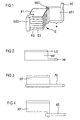
- FIG. 1 shows a detail of an actuator according to the invention, in which for the sake of clarity, only one contact lug KF is shown.
- Core of the actuator is the stack S, which is constructed of alternating electrode layers E1, E2 and ceramic layers KS.
- the actuator shown here with square base surface is provided at opposite corners with metallization MS, which are connected due to the geometric configuration of the electrodes E with each second electrode, so that a parallel interconnection of all individual actuator elements is possible.
- On the first metallization strip MS1 a contact lug KF1 is attached over its entire height with an edge so that a part or the rest of the contact lug protrudes laterally on the stack.
- a connecting element AE is arranged, which projects beyond the stack in height or laterally.
- the width of the protruding portion a is sufficiently selected, cracks occurring in the metallization during the operation or polarity of the actuator, and in particular in the metallization strips MS expire within the contact lug KF, the extent to which the connecting element AE the contact lug KF or the stack S in height or laterally surmounted by the further construction of the actuator, the housing or the other electrical connections.
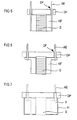
- FIG. 2 shows the simplest embodiment of the invention, in which the contact lug and connecting element are prefabricated from an electrically conductive foil, for example a copper-clad plastic foil.
- the contact lug In the region of its inner edge, the contact lug has a narrow solder layer LS, by means of which a simple soldering of the contact foil to the metallization strips MS is possible. With the help of the solder layer, the contact lug can alternatively be attached directly to the stack or to the electrode layers even without metallization strips.
- a preferred and gentle method of attachment is laser beam soldering which produces only minimal thermal loading of the thermally sensitive multilayer structure.
- Figure 3 shows a further embodiment of the contact lug KF, which in turn is formed as a film with at least one electrically conductive layer.
- the connecting element AE is formed here as a metallic pin, which is electrically connected to the contact lug KF in the region of an outer edge and soldered, for example.
- the pin has, for example, a round cross-section.
- Figure 4 shows another possible embodiment of the contact lug KF, in which the connecting element AE represents a lateral extension of the contact lug. It can be connected as shown in the figure with a metallic pin and thus form a combined connection element.
- the contact lug KF is prefabricated before attaching to the metallizations or directly on the stack, that is, provided with connecting elements AE and possibly the solder layer LS.
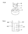
- FIG. 5 shows a partial module of the actuator, comprising the stack S provided with contact lugs KF and a pressure plate DP which has feedthroughs DF for the connection elements AE.
- the bushings DF serve to guide and hold both the connecting elements and the contact lug KF connected thereto.
- the pressure plate DP is disposed on an end face of the stack S and includes, for example, for fixing the stack one of the end surface adapted recess of approximately 50 to 100 ⁇ m depth.
- the further processing for example, the installation in an actuator housing is facilitated, as facilitated by the fixation of stack S, contact lug KF and connecting elements AE in the pressure plate DP, the alignment and centering of the actuator, which is required for optimal transmission of forces becomes.
- FIG. 6 shows a modified partial module with contact lugs KF and connecting elements AE designed according to FIG.
- the connection elements in feedthroughs DF and the stack S are also fixed in a recess of the pressure plate.
- An electrically conductive connection of the connecting elements with the contact lugs is made in this embodiment after the assembly of printing plate and stack, for example by soldering.
- This embodiment has the advantage that pressure plate and connecting elements form a solid unit, which can serve as a plug contact for connection to a current / voltage source, for example at the same time.
- the sealing of the bushings can be made without regard to a mechanical or thermal load on the actuator and can be designed so very tight.
- FIG. 7 The sub-module of pressure plate, connecting elements, tabs and stack is provided for electrical passivation and mechanical protection with a sheath.
- a sleeve H is provided for this purpose, which consists for example of plastic or metal, which is adapted to the size of the sub-module and which seals with the pressure plate.
- the submodule is inserted and then potted or overmolded over a remaining free opening with plastic K, for example, a silicone elastomer.
- plastic K for example, a silicone elastomer.
- both all electrically active surfaces of the stack and the contact lugs are electrically and isolated from environmental influences, as well as a mechanically strong connection between sleeve H, pressure plate DP and stack S produced.
- the lower end face of the stack remains free, since a better force transmission is possible with the preferably ceramic end face of the stack than with the sleeve.
- the ceramic multilayer stack S Before pouring or injecting the submodule into a sleeve, it is possible to additionally passivate the electrically active surfaces of the ceramic multilayer stack S, in particular by applying an electrically insulating, sufficiently elastic plastic compound, for example once again a silicone elastomer.
- the passivation is facilitated by the holder of the contact lug on the fixed in the pressure plate connection elements.
- the passivation prevents that a short circuit between a contact lug and an electrically active surface area of the stack occurs due to the mechanical forces occurring during encapsulation or potting and acting on the contact lugs KF, which could lead to a malfunction of the actuator.
- the flexible contact lugs KF can otherwise be fixed via the connection elements AE, so that the passivation, for example by brush application, is facilitated.
- the connecting elements and optionally also the stack can be fixed in an auxiliary holder.
- the passivation of the stacking surfaces prior to assembly of said sub-module has the advantage that the contact lugs KF can now be arranged closer to the stack before further processing and, for example, also applied. This is a space-saving arrangement in a sleeve H possible.
- a stack with contact lugs resting on the side surfaces is mechanically more stable and additionally protected against mechanical damage during installation in the sleeve or in an actuator housing.
- the contact lugs it is possible to attach the contact lugs to the side surfaces of the stack and to fix there, for example, by an elastic plastic ring which is pushed over the stack together with adjacent contact lugs and connecting elements and presses contact lugs and connecting elements closely to the stack.
- Figure 8 shows a further embodiment of the invention, with a safe installation of the stack including contact lug and connecting elements in a plastic sleeve H is possible.
- the plastic sleeve is not designed as an empty hollow cylinder, but already has an inner profile, which is adapted to the geometric shape of stack, contact lug and connecting elements. After the introduction of the stack in the preformed inner profile of the sleeve H (see direction arrow b) are both stack and contact lugs and connecting elements sufficiently fixed. When now filling with plastic of the remaining spaces to the inner profile damage to the tabs or an unwanted short circuit between the contact lugs and optionally exposed electrically active surfaces of the stack is avoided.
- both the connecting elements AE and the stack S in a holder such as a pressure plate DP (not shown in Figure 8) may be fixed to allow both easier insertion of the stack in the sleeve H, as well as a one-sided to allow hermetically sealed sealing of the stack in the sleeve.
- FIG. 9 shows a further embodiment of the invention, which can be combined with all the already described representations.
- This comprises a stack of two stacked S, S 'existing multi-layer structure, in which the stack S and S' are connected by means of common contact lugs KF and thus fixed against each other.
- Mechanically reinforced connection elements AE for example metallic pins additionally stabilize the arrangement. In this way, it is possible to achieve the necessary overall height of multi-layer structure and thus of possible deflection of the actuator from technologically simpler to produce low stacks, and thereby achieve a simple and elegant connection of the two sub-stacks S, S '.
- Auxiliary support can also serve here for the early centering of several stacks on top of each other, the latter can already be arranged and aligned on a pressure plate. This simplifies the laser beam soldering of the common contact lugs KF to the stacks S and S 'and facilitates the centering of the stacks during injection molding.
Landscapes
- Engineering & Computer Science (AREA)
- Manufacturing & Machinery (AREA)
- General Electrical Machinery Utilizing Piezoelectricity, Electrostriction Or Magnetostriction (AREA)
- Fuel-Injection Apparatus (AREA)
Description
Piezoaktoren bestehen üblicherweise aus mehreren in einem Stapel angeordneten Piezoelementen. Jedes dieser Elemente wiederum besteht aus einer Piezokeramikschicht, die beiderseits mit metallischen Elektroden versehen ist. Wird an diese Elektroden eine Spannung angelegt, so reagiert die Piezokeramikschicht mit einer Gitterverzerrung, die entlang einer Hauptachse zu einer nutzbaren Längenausdehnung führt. Da diese wiederum weniger als zwei Promille der Schichtdicke entlang der Hauptachse beträgt, muß zur Erzielung einer gewünschten absoluten Längenausdehnung eine entsprechend höhere Schichtdicke aktiver Piezokeramik bereitgestellt werden. Mit zunehmender Schichtdicke der Piezokeramikschicht innerhalb eines Piezoelementes steigt jedoch auch die zum Ansprechen des Piezoelementes erforderliche Spannung. Um diese in handhabbaren Grenzen zu erhalten, werden Mehrschichtaktoren hergestellt, bei denen die Dicken von Piezoeinzelelementen üblicherweise zwischen 20 und 200 µm liegen.Piezo actuators usually consist of a plurality of piezo elements arranged in a stack. Each of these elements in turn consists of a piezoceramic layer, which is provided on both sides with metallic electrodes. If a voltage is applied to these electrodes, the piezoceramic layer reacts with a lattice distortion, which leads along a main axis to a usable longitudinal expansion. Since this in turn is less than two parts per thousand of the layer thickness along the main axis, a correspondingly higher layer thickness of active piezoceramic must be provided in order to achieve a desired absolute linear expansion. With increasing layer thickness of the piezoceramic layer within a piezo element, however, the voltage required to respond to the piezo element also increases. In order to obtain these within manageable limits, multi-layer actuators are produced in which the thicknesses of piezo individual elements are usually between 20 and 200 μm.
Bekannte Piezoaktoren in Vielschichtbauweise bestehen daher aus insgesamt bis zu einigen hundert Einzelschichten. Zu deren Herstellung werden Piezokeramikgrünfolien alternierend mit Elektrodenmaterial zu einem Stapel angeordnet und gemeinsam zu einem monolithischen Verbund von bis zu ca. 5 mm Höhe laminiert und gesintert. Größere Aktoren mit größerer absoluter Auslenkung können beispielsweise durch Verkleben mehrerer solcher Stapel erhalten werden. Ausreichend hohe Steifigkeiten, insbesondere wenn mit dem Piezoaktor hohe Kräfte übertragen werden müssen, besitzen nur Piezoaktoren in voll monolithischer Vielschichtbauweise.Known piezoelectric actuators in multilayer construction therefore consist of a total of up to a few hundred individual layers. To produce them piezoceramic green sheets are arranged alternately with electrode material into a stack and laminated together to a monolithic composite of up to about 5 mm in height and sintered. Larger actuators with greater absolute deflection can be obtained, for example, by gluing several such stacks. Sufficient stiffness, especially when high forces have to be transmitted with the piezoelectric actuator, possess only piezo actuators in fully monolithic multilayer construction.
Zur elektrischen Kontaktierung solcher Piezoaktoren in Vielschichtbauweise werden beispielsweise Metallisierungsstreifen an der Außenseite des Piezoaktors oder auch in einer Bohrung in der Flächenmitte der Einzelaktoren angebracht. Um beispielsweise jede zweite Elektrodenschicht mit einem der Metallisierungsstreifen zu verbinden, muß dieser gegen die dazwischenliegenden Elektrodenschichten isoliert werden. Dies gelingt in einfacher Weise dadurch, daß jede zweite Elektrodenschicht im Bereich des einen Metallisierungsstreifens eine Aussparung aufweist, in der sie nicht bis zum Metallisierungsstreifen geführt wird. Die übrigen Elektrodenschichten weisen die Aussparungen dann im Bereich des zweiten Metallisierungsstreifens auf, um eine Kontaktierung mit alternierender Polarität zu ermöglichen. An die Metallisierungsstreifen sind Drähte für den elektrischen Anschluß angelötet. Ein solcher Aktor ist aus EP-A-0 584 842 bekannt.For electrical contacting of such piezo actuators in multilayer construction, for example, metallization on the outside of the piezoelectric actuator or in a bore mounted in the center of the individual actuators. For example, to bond each second electrode layer to one of the metallization strips, it must be isolated from the intervening electrode layers. This is achieved in a simple manner by virtue of the fact that every second electrode layer in the region of the one metallization strip has a recess in which it is not guided to the metallization strip. The remaining electrode layers then have the recesses in the region of the second metallization strip in order to allow contact with alternating polarity. Wires for the electrical connection are soldered to the metallization strips. Such an actuator is known from EP-A-0 584 842.
Piezoaktoren, deren alternierende Kontaktierung über Aussparungen der Elektrodenschichten erfolgt, sind im Kontaktierungsbereich piezoelektrisch inaktiv, da sich dort durch die jeweils eine fehlende Elektrode kein elektrisches Feld aufbauen kann. Dies hat sowohl bei der Polarisation als auch beim Betrieb des Piezoaktors zur Folge, daß sich in diesem piezoelektrisch inaktiven Kontaktierungsbereich mechanische Spannungen aufbauen, die zu Rissen in den inaktiven Bereichen und damit auch an den Metallisierungsstreifen parallel zu den Elektrodenschichten führen können. Dies kann zum vollständigen Durchtrennen der Metallisierungsstreifen führen und hat zur Folge, daß bei punktförmiger Spannungszuführung von außen an die Metallisierungsstreifen ein Teil des Piezoaktors von der Stromversorgung abgehängt und damit inaktiv wird. Die Zahl der Risse hängt von der Gesamthöhe des Aktors sowie von der Festigkeit der Grenzfläche Innenelektrode/Piezokeramik ab und kann sich auch im Dauerbetrieb bei wechselnden Lastbedingungen weiter erhöhen. Da sich beim dynamischen Betrieb außerdem eine dynamische Veränderung der Risse bzw. der Rißöffnungen ergibt, werden dadurch die Metallisierungsstreifen während des Betriebs des Aktors weiter geschädigt.Piezoelectric actuators, whose alternating contacting takes place via recesses of the electrode layers, are piezoelectrically inactive in the contacting region, since no electrical field can build up there through the respective one missing electrode. This has both in the polarization and during operation of the piezoelectric actuator with the result that build up in this piezoelectrically inactive contacting region mechanical stresses that can lead to cracks in the inactive areas and thus also on the metallization parallel to the electrode layers. This can lead to complete severing of the metallization and has the consequence that when punctiform voltage supply from the outside of the metallization a part of the piezoelectric actuator is suspended from the power supply and thus inactive. The number of cracks depends on the total height of the actuator as well as the strength of the internal electrode / piezoceramic interface and can continue to increase in continuous operation under changing load conditions. Since a dynamic change of the cracks or the crack openings also results during dynamic operation, the metallization strips are thereby further damaged during the operation of the actuator.
Aufgabe der vorliegenden Erfindung ist es, einen keramischen Aktor samt Herstellverfahren anzugeben, der eine sichere und gut handhabbare elektrische Kontaktierung besitzt, die eine erhöhte Stabilität gegenüber einer Rißbildung zeigt.Object of the present invention is to provide a ceramic actuator including manufacturing process, the safe and has good manageable electrical contact, which shows an increased stability against cracking.
Diese Aufgabe wird erfindungsgemäß durch einen Aktor nach Anspruch 1 gelöst. Vorteilhafte Ausgestaltungen der Erfindung sowie ein Verfahren zur Herstellung des Piezoaktors sind weiteren Ansprüchen zu entnehmen.This object is achieved by an actuator according to claim 1. Advantageous embodiments of the invention and a method for producing the piezoelectric actuator can be found in further claims.
Der erfindungsgemäße Aktor kann einen herkömmlichen und vorzugsweise monolithischen Aufbau besitzen. Stapelartig sind alternierend piezoelektrische Keramikschichten und Elektrodenschichten übereinander angeordnet und vorzugsweise zusammen gesintert. Außen am Stapel sind zur alternierenden Kontaktierung der Elektrodenschichten erfindungsgemäß zumindest zwei elektrisch leitende Kontaktfahnen vorgesehen. Diese sind über eine Kante mit den Elektrodenschichten verbunden und erstrecken sich über die gesamte Höhe des elektrisch aktiven Bereichs des Stapels. Seitlich der verbundenen Kante weisen sie einen überstehenden Bereich und im Bereich der vom Stapel wegweisenden Außenkante ein seitlich oder den Stapel in der Höhe überragendes elektrisches Anschlußelement auf.The actuator according to the invention may have a conventional and preferably monolithic structure. Stack-like piezoelectric ceramic layers and electrode layers are arranged one above the other alternately and preferably sintered together. According to the invention, at least two electrically conductive contact lugs are provided on the outside of the stack for alternating contacting of the electrode layers. These are connected by an edge to the electrode layers and extend over the entire height of the electrically active region of the stack. Laterally of the connected edge, they have a projecting area and in the area of the outer edge facing away from the stack there is an electrical connection element protruding laterally or stackwise in height.
Mit der Kontaktfahne ist es möglich, eventuell im Betrieb des Aktors auftretende Risse in den Metallisierungen elektrisch leitend zu überbrücken. Wird der überstehende Bereich ausreichend breit gewählt, so laufen die Risse innerhalb der Kontaktfahne bzw. innerhalb des überstehenden Bereichs aus. So bleiben sämtliche Einzelelemente des Aktors elektrisch funktionsfähig, selbst wenn Risse an den Metallisierungen auftreten. Der erfindungsgemäße Aktor zeigt daher beim Betrieb keinerlei Leistungseinbußen.With the contact lug, it is possible to electrically bridge any cracks occurring in the metallization during operation of the actuator. If the projecting area is chosen to be sufficiently wide, the cracks will run out within the contact lug or within the projecting area. Thus, all the individual elements of the actuator remain electrically functional, even if cracks occur at the metallizations. The actuator according to the invention therefore shows no performance losses during operation.
Das Anschlußelement an der Außenkante ermöglicht den einfachen Anschluß der Kontaktfahne an eine externe Strom- oder Spannungsversorgung. Es überragt die Kontaktfahne seitlich oder den Stapel in der Höhe und ist so auch beim Einbau des Stapels in ein Gehäuse noch gut zugänglich und ermöglicht so einen einfachen Stromanschluß.The connecting element on the outer edge allows easy connection of the contact lug to an external power or voltage supply. It surmounted the contact lug on the side or the stack in height and is so even when installing the Stack in a housing still easily accessible, allowing a simple power connection.
In der einfachsten Ausführungsform ist das Anschlußelement aus dem Material der Kontaktfahne hergestellt, bzw. integraler Bestandteil der Kontaktfahne. Diese umfaßt zumindest eine elektrisch leitende Schicht. Vorzugsweise besteht sie jedoch aus einem Verbundmaterial mit mindestens einer Kunststoffolie und mindestens einer metallischen Folie oder Schicht. Ein solches Verbundmaterial weist eine hohe Flexibilität bei gleichzeitig hoher Reißfestigkeit und Elastizität auf. Geometrisch stellt das Anschlußelement eine Verlängerung der vom Stapel wegweisenden Außenkante der Kontaktfahne nach oben oder eine Verlängerung der oberen Kante nach außen beziehungsweise zur Seite dar. Neben dem dadurch erleichterten Anschluß dient das Anschlußelement auch zur leichteren Handhabung der Kontaktfahne bzw. des mit der Kontaktfahne versehenen Aktors, insbesondere während des Einbaus in ein Gehäuse. Dabei können die Anschlußelemente als Führung dienen.In the simplest embodiment, the connecting element is made of the material of the contact lug, or an integral part of the contact lug. This comprises at least one electrically conductive layer. Preferably, however, it consists of a composite material with at least one plastic film and at least one metallic film or layer. Such a composite material has a high flexibility with high tear resistance and elasticity. Geometrically, the connecting element represents an extension of the edge facing away from the stack outer edge of the contact lug up or an extension of the upper edge to the outside or to the side. In addition to the facilitated connection, the connection element also serves to facilitate handling of the contact lug and provided with the contact lug actuator especially during installation in a housing. The connection elements can serve as a guide.
Vorzugsweise ist das Anschlußelement daher so ausgebildet, daß es eine zusätzliche mechanische Verstärkung der Außenkante der Kontaktfahne darstellt. In einer vorteilhaften Ausgestaltung ist das Anschlußelement als metallischer Anschlußstift ausgebildet. Dieser kann auf der Kontaktfahne bzw. auf deren metallischer Schicht aufgelötet oder anderweitig elektrisch leitend befestigt sein. Der Anschlußstift kann sich über die gesamte Außenkante erstrecken oder nur mit einem Teil der Kante verbunden sein. Mit einem derartig mechanisch verstärkenden Anschlußelement wird die Führung bzw. Handhabung der am Stapel befestigten Kontaktfahne erleichtert.Preferably, the connection element is therefore designed so that it represents an additional mechanical reinforcement of the outer edge of the contact lug. In an advantageous embodiment, the connecting element is designed as a metallic pin. This can be soldered to the contact lug or on its metallic layer or otherwise electrically conductively attached. The terminal pin may extend over the entire outer edge or be connected only to a part of the edge. With such a mechanically reinforcing connecting element, the guidance or handling of the contact lug attached to the stack is facilitated.
Das als Anschlußstift ausgebildete Anschlußelement kann zusätzlich Teil einer elektrischen Steckverbindung sein. Dadurch wird eine äußerst einfache Verbindung zu einer elektrischen Spannungsquelle ermöglicht.The connecting element formed as a connecting pin may additionally be part of an electrical plug connection. This allows a very simple connection to an electrical voltage source.
Vorzugsweise weist der Aktor an einer Stirnfläche des Stapels eine Druckplatte auf. Diese besitzt Öffnungen, durch die die Anschlußelemente gesteckt oder geleitet werden. Bei mechanisch verstärkten Anschlußelementen sind die Öffnungen so gestaltet, daß eine Führung und Halterung der Anschlußelemente gewährleistet ist.The actuator preferably has a pressure plate on an end face of the stack. This has openings through which the connecting elements are inserted or passed. In mechanically reinforced connection elements, the openings are designed so that a guide and holding the connection elements is ensured.
Vorzugsweise besitzt die Druckplatte eine Ausnehmung zur Fixierung des Stapels darin. Dies ermöglicht einen sicheren Einbau des Stapels einschließlich der Kontaktfahne in ein Aktorgehäuse, wobei der Stapel sicher ausgerichtet und zentriert wird.Preferably, the pressure plate has a recess for fixing the stack therein. This allows for safe installation of the stack, including the contact lug, into an actuator housing, with the stack securely aligned and centered.
In der Druckplatte können noch andere Elemente des Aktors integriert sein, beispielsweise Kraftsensoren, Temperatursensoren, andere Sensoren (z.B. Hallsensoren) oder ein zweiter Aktor als Justierglied für die Steifigkeit, zur Temperaturausdehnungskompensation und zur Nullpunktsjustierung.Other elements of the actuator may be integrated in the pressure plate, such as force sensors, temperature sensors, other sensors (e.g., Hall sensors), or a second actuator as an adjusting element for stiffness, thermal expansion compensation and zero point adjustment.
Zum mechanischen Schutz des Stapels im Aktor weist dieser eine Kunststoffumhüllung auf. Dazu ist der Stapel vorzugsweise in eine Kunststoffhülse eingegossen oder mit einem Kunststoff umspritzt. Dafür eignen sich insbesondere Elastomere auf Silikonharzbasis. Der Einbau in die Kunststoffhülse kann dabei mit Hilfe der Druckplatte erfolgen, wobei eine einfache Führung und Fixierung von Stapel, Kontaktfahne und Anschlußelement erreicht wird.For mechanical protection of the stack in the actuator, this has a plastic sheath. For this purpose, the stack is preferably cast in a plastic sleeve or molded with a plastic. Elastomers based on silicone resin are particularly suitable for this purpose. The installation in the plastic sleeve can be done with the help of the pressure plate, with a simple guidance and fixation of stack, contact lug and connection element is achieved.
In Längsrichtung des Aktors können beim Eingießen oder Umspritzen mit Kunststoff die anderen bereits oben genannten und den Aktor komplettierenden Elemente mit in die Umhüllung eingebaut werden, sofern sie nicht anderweitig und zum Beispiel in die Druckplattte eingebaut sind.In the longitudinal direction of the actuator, the other already mentioned above and the actuator completing elements can be incorporated into the enclosure when pouring or encapsulating with plastic, unless they are otherwise installed and, for example, in the pressure plate.
Im folgenden wird der erfindungsgemäße Aktor sowie ein Verfahren zu dessen Kontaktierung anhand von Ausführungsbeispielen und der dazugehörigen neun Figuren näher erläutert.
- Figur 1
- zeigt einen Aktor mit Kontaktfahne und Anschlußelement in schematischer perspektivischer Darstellung.
- Figuren 2 bis 4
- zeigen in schematischer Darstellung verschiedene Kontaktfahnen.
- Figuren 5 und 6
- zeigen schematische Querschnitte durch erfindungsgemäße Aktoren mit Druckplatte.
- Figur 7
- zeigt im schematischen Querschnitt einen Aktor mit Kunststoffhülse.
- Figur 8
- zeigt in schematischer perspektivischer Darstellung den Einbau eines Stapels in eine Kunststoffhülse.
- Figur 9
- zeigt einen aus mehreren Stapeln aufgebauten Aktor.
- FIG. 1
- shows an actuator with contact lug and connecting element in a schematic perspective view.
- FIGS. 2 to 4
- show a schematic representation of different contact flags.
- FIGS. 5 and 6
- show schematic cross-sections of actuators according to the invention with pressure plate.
- FIG. 7
- shows in schematic cross section an actuator with plastic sleeve.
- FIG. 8
- shows a schematic perspective view of the installation of a stack in a plastic sleeve.
- FIG. 9
- shows an actuator constructed of several stacks.
Figur 1 zeigt ausschnittsweise einen erfindungsgemäßen Aktor, bei dem der Übersichtlichkeit halber nur eine Kontaktfahne KF dargestellt ist. Kern des Aktors ist der Stapel S, der alternierend aus Elektrodenschichten E1, E2 und Keramikschichten KS aufgebaut ist. Der hier mit quadratischer Grundfläche dargestellte Aktor ist an einander gegenüberliegenden Ecken mit Metallisierungsstreifen MS versehen, die aufgrund der geometrischen Ausgestaltung der Elektroden E mit jeweils jeder zweiten Elektrode verbunden sind, so daß eine parallele Verschaltung sämtlicher einzelner Aktorelemente möglich ist. Am ersten Metallisierungsstreifen MS1 ist über dessen gesamte Höhe eine Kontaktfahne KF1 mit einer Kante so befestigt, daß ein Teil beziehungsweise der Rest der Kontaktfahne seitlich am Stapel übersteht. Im Bereich der vom Stapel wegweisenden Außenkante ist ein Anschlußelement AE angeordnet, welches den Stapel in der Höhe oder seitlich überragt. Während die Breite des überstehenden Bereichs a ausreichend gewählt wird, daß während des Betriebs oder der Polung des Aktors auftretende Risse in der Metallisierung und insbesondere in den Metallisierungsstreifen MS innerhalb der Kontaktfahne KF auslaufen, ist das Ausmaß, in dem das Anschlußelement AE die Kontaktfahne KF bzw. den Stapel S in der Höhe oder seitlich überragt, von der weiteren Konstruktion des Aktors, dessen Gehäuse oder der weiteren elektrischen Anschlüsse abhängig.Figure 1 shows a detail of an actuator according to the invention, in which for the sake of clarity, only one contact lug KF is shown. Core of the actuator is the stack S, which is constructed of alternating electrode layers E1, E2 and ceramic layers KS. The actuator shown here with square base surface is provided at opposite corners with metallization MS, which are connected due to the geometric configuration of the electrodes E with each second electrode, so that a parallel interconnection of all individual actuator elements is possible. On the first metallization strip MS1 a contact lug KF1 is attached over its entire height with an edge so that a part or the rest of the contact lug protrudes laterally on the stack. In the area facing away from the stack outer edge, a connecting element AE is arranged, which projects beyond the stack in height or laterally. While the width of the protruding portion a is sufficiently selected, cracks occurring in the metallization during the operation or polarity of the actuator, and in particular in the metallization strips MS expire within the contact lug KF, the extent to which the connecting element AE the contact lug KF or the stack S in height or laterally surmounted by the further construction of the actuator, the housing or the other electrical connections.
Figur 2 zeigt die einfachste Ausgestaltung der Erfindung, bei der Kontaktfahne und Anschlußelement vorkonfektioniert aus einer elektrisch leitenden Folie, beispielsweise einer kupferkaschierten Kunststoffolie ausgebildet sind. Im Bereich ihrer Innenkante weist die Kontaktfahne eine schmale Lotschicht LS auf, mit deren Hilfe ein einfaches Auflöten der Kontaktfolie an die Metallisierungsstreifen MS möglich ist. Mit Hilfe der Lotschicht kann die Kontaktfahne alternativ auch ohne Metallisierungsstreifen direkt am Stapel beziehungsweise an den Elektrodenschichten befestigt werden.FIG. 2 shows the simplest embodiment of the invention, in which the contact lug and connecting element are prefabricated from an electrically conductive foil, for example a copper-clad plastic foil. In the region of its inner edge, the contact lug has a narrow solder layer LS, by means of which a simple soldering of the contact foil to the metallization strips MS is possible. With the help of the solder layer, the contact lug can alternatively be attached directly to the stack or to the electrode layers even without metallization strips.
Ein bevorzugtes und schonendes Verfahren zum Befestigen ist das Laserstrahllöten, das nur eine minimale Wärmebelastung des thermisch empfindlichen Mehrschichtaufbaus erzeugt.A preferred and gentle method of attachment is laser beam soldering which produces only minimal thermal loading of the thermally sensitive multilayer structure.
Figur 3 zeigt eine weitere Ausgestaltung der Kontaktfahne KF, die wiederum als Folie mit zumindest einer elektrisch leitenden Schicht ausgebildet ist. Das Anschlußelement AE ist hier als metallischer Anschlußstift ausgebildet, der elektrisch leitend mit der Kontaktfahne KF im Bereich einer Außenkante verbunden und beispielsweise aufgelötet ist. Der Anschlußstift weist beispielsweise einen runden Querschnitt auf.Figure 3 shows a further embodiment of the contact lug KF, which in turn is formed as a film with at least one electrically conductive layer. The connecting element AE is formed here as a metallic pin, which is electrically connected to the contact lug KF in the region of an outer edge and soldered, for example. The pin has, for example, a round cross-section.
Figur 4 zeigt eine weitere mögliche Ausgestaltung der Kontaktfahne KF, bei der das Anschlußelement AE eine seitliche Verlängerung der Kontaktfahne darstellt. Es kann wie in der Figur dargestellt mit einem metallischen Anschlußstift verbunden sein und so ein kombiniertes Anschlußelement bilden.Figure 4 shows another possible embodiment of the contact lug KF, in which the connecting element AE represents a lateral extension of the contact lug. It can be connected as shown in the figure with a metallic pin and thus form a combined connection element.
In allen Fällen wird die Kontaktfahne KF vor dem Befestigen an den Metallisierungen oder direkt am Stapel fertig konfektioniert, das heißt, mit Anschlußelementen AE und gegebenenfalls der Lotschicht LS versehen.In all cases, the contact lug KF is prefabricated before attaching to the metallizations or directly on the stack, that is, provided with connecting elements AE and possibly the solder layer LS.
Während des Auflötens oder der anderweitigen elektrisch leitenden Befestigung der Kontaktfahne an den Metallisierungen werden diese elektrisch kurzgeschlossen, um eine Beschädigung des zum Beispiel piezoelektrischen Aktors über den pyroelektrischen Effekt zu vermeiden. Mit derselben Maßnahme werden auch bei späteren Verarbeitungsschritten Beschädigungen immer dann vermieden, wenn thermische Belastungen des Stapels zu erwarten sind.During the soldering or otherwise electrically conductive attachment of the contact lug to the metallizations, these are electrically short-circuited in order to avoid damage to the piezoelectric actuator, for example, via the pyroelectric effect. With the same measure, damage is always avoided even in later processing steps when thermal loads on the stack are to be expected.
Figur 5 zeigt ein Teilmodul des Aktors, bestehend aus dem mit Kontaktfahnen KF versehenen Stapel S und einer Druckplatte DP, die Durchführungen DF für die Anschlußelemente AE aufweist. Insbesondere bei mechanisch verstärkten Anschlußelementen, beispielsweise den metallischen Anschlußstiften, dienen die Durchführungen DF zur Führung und Halterung sowohl der Anschlußelemente als auch der damit verbundenen Kontaktfahne KF. Die Druckplatte DP ist über einer Stirnfläche des Stapels S angeordnet und weist beispielsweise zur Fixierung des Stapels eine der Stirnfläche angepaßte Vertiefung von ca. 50 bis 100 µm Tiefe auf. Mit diesem Teilmodul wird die Weiterverarbeitung, beispielsweise der Einbau in ein Aktorgehäuse erleichtert, da durch die Fixierung von Stapel S, Kontaktfahne KF und Anschlußelementen AE in der Druckplatte DP die Ausrichtung und Zentrierung des Aktors, die für eine optimale Übertragung der Kräfte erforderlich ist, erleichtert wird.FIG. 5 shows a partial module of the actuator, comprising the stack S provided with contact lugs KF and a pressure plate DP which has feedthroughs DF for the connection elements AE. In particular, in the case of mechanically reinforced connecting elements, for example the metallic connecting pins, the bushings DF serve to guide and hold both the connecting elements and the contact lug KF connected thereto. The pressure plate DP is disposed on an end face of the stack S and includes, for example, for fixing the stack one of the end surface adapted recess of approximately 50 to 100 μ m depth. With this sub-module, the further processing, for example, the installation in an actuator housing is facilitated, as facilitated by the fixation of stack S, contact lug KF and connecting elements AE in the pressure plate DP, the alignment and centering of the actuator, which is required for optimal transmission of forces becomes.
Figur 6 zeigt ein abgewandeltes Teilmodul mit gemäß Figur 4 ausgestalteten Kontaktfahnen KF und Anschlußelementen AE. Wie in Figur 5 sind auch hier die Anschlußelemente in Durchführungen DF und der Stapel S in einer Ausnehmung der Druckplatte fixiert. In dieser Ausgestaltung ist es möglich, die Kontaktfahnen zunächst ohne Anschlußelemente AE an den Metallisierungsstreifen des Stapels S zu befestigen und dafür die Druckplatte DP fest mit den Anschlußelementen AE zu verbinden. Eine elektrisch leitende Verbindung der Anschlußelemente mit den Kontaktfahnen wird in dieser Ausführungsform nach dem Zusammenfügen von Druckplatte und Stapel vorgenommen, beispielsweise durch Löten. Diese Ausführung hat den Vorteil, daß Druckplatte und Anschlußelemente eine feste Einheit bilden, die beispielsweise gleichzeitig als Steckkontakt zur Verbindung mit einer Strom-/Spannungsquelle dienen können. Die Abdichtung der Durchführungen kann ohne Rücksicht auf eine mechanische oder thermische Belastung des Aktors vorgenommen werden und kann so besonders dicht ausgeführt sein.FIG. 6 shows a modified partial module with contact lugs KF and connecting elements AE designed according to FIG. As in FIG. 5, the connection elements in feedthroughs DF and the stack S are also fixed in a recess of the pressure plate. In this embodiment, it is possible to first attach the tabs without connecting elements AE to the metallization of the stack S and for the pressure plate DP to connect firmly with the connecting elements AE. An electrically conductive connection of the connecting elements with the contact lugs is made in this embodiment after the assembly of printing plate and stack, for example by soldering. This embodiment has the advantage that pressure plate and connecting elements form a solid unit, which can serve as a plug contact for connection to a current / voltage source, for example at the same time. The sealing of the bushings can be made without regard to a mechanical or thermal load on the actuator and can be designed so very tight.
Figur 7: Das Teilmodul aus Druckplatte, Anschlußelementen, Kontaktfahnen und Stapel wird zur elektrischen Passivierung und zum mechanischen Schutz mit einer Umhüllung versehen. Im Ausführungsbeispiel ist dazu eine Hülse H vorgesehen, die zum Beispiel aus Kunststoff oder Metall besteht, die der Größe des Teilmoduls angepaßt ist und die mit der Druckplatte dicht abschließt. In diese Hülse H wird das Teilmodul eingesteckt und anschließend über eine freibleibende Öffnung mit Kunststoff K, beispielsweise einem Silikonelastomer vergossen oder umspritzt. Dabei werden sowohl sämtliche elektrisch aktiven Oberflächen des Stapels und der Kontaktfahnen elektrisch und von Umwelteinflüssen isoliert, als auch eine mechanisch feste Verbindung zwischen Hülse H, Druckplatte DP und Stapel S hergestellt. Bei einer aus Kunststoff bestehenden Hülse H bleibt dabei die untere Stirnfläche des Stapels frei, da mit der vorzugsweise keramischen Stirnfläche des Stapels eine bessere Kraftübertragung als mit der Hülse möglich ist.Figure 7: The sub-module of pressure plate, connecting elements, tabs and stack is provided for electrical passivation and mechanical protection with a sheath. In the embodiment, a sleeve H is provided for this purpose, which consists for example of plastic or metal, which is adapted to the size of the sub-module and which seals with the pressure plate. In this sleeve H, the submodule is inserted and then potted or overmolded over a remaining free opening with plastic K, for example, a silicone elastomer. In this case, both all electrically active surfaces of the stack and the contact lugs are electrically and isolated from environmental influences, as well as a mechanically strong connection between sleeve H, pressure plate DP and stack S produced. In the case of a sleeve H made of plastic, the lower end face of the stack remains free, since a better force transmission is possible with the preferably ceramic end face of the stack than with the sleeve.
Vor dem Eingießen oder Einspritzen des Teilmoduls in eine Hülse ist es möglich, die elektrisch aktiven Oberflächen des keramischen Mehrschichtstapels S zusätzlich zu passivieren, insbesondere durch Auftrag einer elektrisch isolierenden ausreichend elastischen Kunststoffmasse, beispielsweise wiederum einem Silikonelastomer. Die Passivierung wird durch die Halterung der Kontaktfahne über die in der Druckplatte fixierten Anschlußelemente erleichtert. Außerdem verhindert die Passivierung, daß durch die beim Umspritzen oder Vergießen auftretenden und auf die Kontaktfahnen KF einwirkenden mechanischen Kräfte ein Kurzschluß zwischen einer Kontaktfahne und einem elektrisch aktiven Oberflächenbereich des Stapels erfolgt, der zu einer Fehlfunktion des Aktors führen könnte.Before pouring or injecting the submodule into a sleeve, it is possible to additionally passivate the electrically active surfaces of the ceramic multilayer stack S, in particular by applying an electrically insulating, sufficiently elastic plastic compound, for example once again a silicone elastomer. The passivation is facilitated by the holder of the contact lug on the fixed in the pressure plate connection elements. In addition, the passivation prevents that a short circuit between a contact lug and an electrically active surface area of the stack occurs due to the mechanical forces occurring during encapsulation or potting and acting on the contact lugs KF, which could lead to a malfunction of the actuator.
Erfolgt der Auftrag der Passivierung vor der Herstellung eines Teilmoduls aus Stapel und Druckplatte, so können die flexiblen Kontaktfahnen KF dabei anderweitig über die Anschlußelemente AE fixiert werden, so daß die Passivierung, beispielsweise durch Pinselauftrag, erleichtert wird. Dazu können die Anschlußelemente und gegebenenfalls auch der Stapel in einer Hilfshalterung fixiert werden. Die Passivierung der Stapeloberflächen vor dem Zusammenfügen des genannten Teilmoduls hat den Vorteil, daß die Kontaktfahnen KF nun vor der Weiterverarbeitung enger am Stapel angeordnet und beispielsweise auch angelegt werden können. Damit wird eine raumsparendere Anordnung in einer Hülse H möglich. Ein Stapel mit an den Seitenflächen anliegenden Kontaktfahnen ist mechanisch stabiler und zusätzlich vor mechanischen Beschädigungen während des Einbaus in die Hülse oder in ein Aktorgehäuse geschützt. In einer Ausgestaltung der Erfindung ist es möglich, die Kontaktfahnen an die Seitenflächen des Stapels anzudrükken und dort zu fixieren, beispielsweise durch einen elastischen Kunststoffring, der über den Stapel samt anliegenden Kontaktfahnen und Anschlußelementen geschoben wird und Kontaktfahnen und Anschlußelemente eng an den Stapel andrückt.If the passivation is carried out before the production of a partial module of stack and pressure plate, the flexible contact lugs KF can otherwise be fixed via the connection elements AE, so that the passivation, for example by brush application, is facilitated. For this purpose, the connecting elements and optionally also the stack can be fixed in an auxiliary holder. The passivation of the stacking surfaces prior to assembly of said sub-module has the advantage that the contact lugs KF can now be arranged closer to the stack before further processing and, for example, also applied. This is a space-saving arrangement in a sleeve H possible. A stack with contact lugs resting on the side surfaces is mechanically more stable and additionally protected against mechanical damage during installation in the sleeve or in an actuator housing. In one embodiment of the invention, it is possible to attach the contact lugs to the side surfaces of the stack and to fix there, for example, by an elastic plastic ring which is pushed over the stack together with adjacent contact lugs and connecting elements and presses contact lugs and connecting elements closely to the stack.
Figur 8 zeigt eine weitere Ausgestaltung der Erfindung, mit der ein sicherer Einbau des Stapels samt Kontaktfahne und Anschlußelemente in eine Kunststoffhülse H möglich ist. Die Kunststoffhülse ist dabei nicht als leerer Hohlzylinder ausgebildet, sondern weist bereits ein Innenprofil auf, das der geometrischen Form von Stapel, Kontaktfahne und Anschlußelementen angepaßt ist. Nach dem Einbringen des Stapels in das vorgebildete Innenprofil der Hülse H (siehe Richtungspfeil b) sind sowohl Stapel als auch Kontaktfahnen und Anschlußelemente ausreichend fixiert. Beim nun folgenden Auffüllen mit Kunststoff der verbleibenden Zwischenräume zum Innenprofil wird so eine Beschädigung der Kontaktfahnen bzw. ein ungewollter Kurzschluß zwischen Kontaktfahnen und gegebenenfalls freiliegenden elektrisch aktiven Oberflächen des Stapels vermieden. Auch in dieser Ausführung können sowohl die Anschlußelemente AE als auch der Stapel S in einer Halterung, beispielsweise einer Druckplatte DP (in Figur 8 nicht dargestellt) fixiert sein, um sowohl ein leichteres Einbringen des Stapels in die Hülse H zu ermöglichen, als auch eine einseitig hermetisch dichte Versiegelung des Stapels in der Hülse zu ermöglichen.Figure 8 shows a further embodiment of the invention, with a safe installation of the stack including contact lug and connecting elements in a plastic sleeve H is possible. The plastic sleeve is not designed as an empty hollow cylinder, but already has an inner profile, which is adapted to the geometric shape of stack, contact lug and connecting elements. After the introduction of the stack in the preformed inner profile of the sleeve H (see direction arrow b) are both stack and contact lugs and connecting elements sufficiently fixed. When now filling with plastic of the remaining spaces to the inner profile damage to the tabs or an unwanted short circuit between the contact lugs and optionally exposed electrically active surfaces of the stack is avoided. Also in this embodiment, both the connecting elements AE and the stack S in a holder, such as a pressure plate DP (not shown in Figure 8) may be fixed to allow both easier insertion of the stack in the sleeve H, as well as a one-sided to allow hermetically sealed sealing of the stack in the sleeve.
Figur 9 zeigt eine weitere Ausgestaltung der Erfindung, die mit sämtlichen bereits beschriebenen Darstellungen kombiniert werden kann. Diese umfaßt einen aus zwei übereinander angeordneten Stapeln S, S' bestehenden Mehrschichtaufbau, bei dem die Stapel S und S' mittels gemeinsamer Kontaktfahnen KF verbunden und damit gegeneinander fixiert sind. Mechanisch verstärkte Anschlußelemente AE, beispielsweise metallische Anschlußstifte stabilisieren die Anordnung zusätzlich. Auf diese Weise ist es möglich, aus technologisch einfacher herzustellenden niedrigen Stapeln dennoch die nötige Gesamthöhe an Mehrschichtaufbau und damit an möglicher Auslenkung des Aktors zu erreichen, und dabei eine einfache und elegante Verbindung der beiden Teilstapel S, S' zu erzielen. Hilfshalterung kann auch hier zur frühzeitigen Zentrierung von mehreren Stapeln übereinander dienen, wobei letztere bereits an einer Druckplatte angeordnet und ausgerichtet werden können. Damit wird die Laserstrahllötung der gemeinsamen Kontaktfahnen KF an die Stapel S und S' vereinfacht und die Zentrierung der Stapel beim Spritzguß erleichtert.Figure 9 shows a further embodiment of the invention, which can be combined with all the already described representations. This comprises a stack of two stacked S, S 'existing multi-layer structure, in which the stack S and S' are connected by means of common contact lugs KF and thus fixed against each other. Mechanically reinforced connection elements AE, for example metallic pins additionally stabilize the arrangement. In this way, it is possible to achieve the necessary overall height of multi-layer structure and thus of possible deflection of the actuator from technologically simpler to produce low stacks, and thereby achieve a simple and elegant connection of the two sub-stacks S, S '. Auxiliary support can also serve here for the early centering of several stacks on top of each other, the latter can already be arranged and aligned on a pressure plate. This simplifies the laser beam soldering of the common contact lugs KF to the stacks S and S 'and facilitates the centering of the stacks during injection molding.
Claims (17)
- Ceramic actuator- with a multilayer structure, having at least one stack (S) of alternating electrode layers (E) and ceramic layers (KS);- with at least two strip-shaped electrically-conductive contact lugs (KF), which are attached to each stack laterally,characterised in that- each contact lug (KF) is connected to the electrode layers in an electrically-conductive manner by way of an edge and has a protruding region (a) to the side of said edge;- each contact lug (KF) has an electrical terminal element (AE) projecting beyond the contact lug laterally or beyond the height of the stack, disposed in the region of the outer edge of the respective contact lug facing away from the stack.
- Actuator according to claim 1,
wherein the terminal element (AE) has a metal terminal pin, which mechanically reinforces the outer edge of the contact lug (AE) and extends along the outer edge over the entire height of the contact lug. - Actuator according to claim 1 or 2,
wherein the terminal element (AE) has a strip-shaped extension of the contact lug, which is connected to metal terminal pins. - Actuator according to claim 2 or 3,
wherein a pressure plate (DP) is disposed over a front face of the stack (S), through which pressure plate (DP) the terminal pins (AE) are inserted and fixed thereto. - Actuator according to one of claims 2 to 4,
wherein the terminal pins (AE) are configured as plug-in contacts. - Actuator according to claim 4,
wherein a recess is provided in the pressure plate (DP), in which recess the stack (S) is fixed. - Actuator according to one of claims 1 to 6,
wherein plastic is moulded or cast all round the stack (S) and contact lugs (KF) to form a compact plastic envelope and
wherein the electrical terminal elements (AE) exit from the plastic envelope (H) on a front face. - Actuator according to claim 7,
wherein the plastic envelope is made from a silicone elastomer (K). - Actuator according to one of claims 1 to 7,
wherein a number of stacks (S, S') are disposed one above the other and connected to common contact lugs (KF). - Method for contacting a ceramic actuator with a multilayer structure,- wherein a stack (S) forming the multilayer structure is made from alternating electrode layers and ceramic layers (E1, KS, E2),- wherein contact lugs (KF) tailored in size to the height of the multilayer structure are made of a film having at least one electrically-conductive layer and electrical terminal elements (AE) are provided therein in the region of an edge of the contact lug, said terminal elements (AE) projecting beyond the contact lug laterally or beyond the height of the multilayer structure,- wherein at least two contact lugs are connected by way of an edge to the stack (S) laterally, such that a laterally protruding region (a) remains, with an electrically-conductive contact with the electrode layers being produced.
- Method according to claim 10,
wherein the stack (S) is provided laterally with at least two strip-shaped metallizing components (MS) to enable contacting of the electrode layers and wherein the contact lugs are secured to the metallizing strip-shaped components. - Method according to claim 10 or 11,
wherein the securing is carried out by laser soldering. - Method according to one of claims 10 to 12,
wherein metal pins are provided as the terminal elements (AE), said metal pins being soldered to the contact lugs before the contact lugs (KF) are secured in the region of the edge opposite the stack. - Method according to one of claims 10 to 13,
wherein the electrically-active surface of the stack (S) is covered, after the securing of the contact lugs (KF), with an electrically-insulating organic passivation layer, such that at least the terminal elements (AE) of the contact lugs remain free and the front faces of the stack (S) remain free. - Method according to one of claims 10 to 14,
wherein, after the contact lugs (KF) have been secured, the stack (S) is inserted into a plastic sleeve (H) and plastic (K) is cast or moulded around it such that the ends of the terminal elements (AE) remain free. - Method according to claim 15,
wherein a pressure plate (DP) is provided with through-holes (DF), through which the terminal elements (AE) are passed,
wherein the stack (S) is fixed in the pressure plate (DP) and is then cast or moulded in the plastic sleeve (H). - Method according to one of claims 10 to 16,
wherein two stacks (S, S') are disposed one above the other, provided with common contact lugs (KF1, KF2) and thus connected to form a double stack.
Applications Claiming Priority (3)
| Application Number | Priority Date | Filing Date | Title |
|---|---|---|---|
| DE19715488 | 1997-04-14 | ||
| DE19715488A DE19715488C1 (en) | 1997-04-14 | 1997-04-14 | Piezoelectric actuator |
| PCT/DE1998/000917 WO1998047187A1 (en) | 1997-04-14 | 1998-03-31 | Piezo actuator with novel contacting and production method |
Publications (2)
| Publication Number | Publication Date |
|---|---|
| EP0976165A1 EP0976165A1 (en) | 2000-02-02 |
| EP0976165B1 true EP0976165B1 (en) | 2007-01-24 |
Family
ID=7826438
Family Applications (1)
| Application Number | Title | Priority Date | Filing Date |
|---|---|---|---|
| EP98928099A Expired - Lifetime EP0976165B1 (en) | 1997-04-14 | 1998-03-31 | Piezo actuator with novel contacting and production method |
Country Status (5)
| Country | Link |
|---|---|
| US (1) | US6316863B1 (en) |
| EP (1) | EP0976165B1 (en) |
| JP (1) | JP4229986B2 (en) |
| DE (2) | DE19715488C1 (en) |
| WO (1) | WO1998047187A1 (en) |
Families Citing this family (48)
| Publication number | Priority date | Publication date | Assignee | Title |
|---|---|---|---|---|
| DE19930585B4 (en) * | 1998-08-06 | 2017-11-09 | Epcos Ag | Piezoelectric actuator with improved electrical contacting and use of such a piezoelectric actuator |
| DE19856202A1 (en) * | 1998-12-05 | 2000-06-15 | Bosch Gmbh Robert | Piezoelectric actuator |
| DE19914411A1 (en) | 1999-03-30 | 2000-10-12 | Bosch Gmbh Robert | Piezoelectric actuator |
| DE19928189A1 (en) * | 1999-06-19 | 2001-04-19 | Bosch Gmbh Robert | Piezo actuator |
| DE19928178A1 (en) * | 1999-06-19 | 2000-08-10 | Bosch Gmbh Robert | Piezoactuator e.g. for valve, has multilayer construction of piezo layers, intermediate electrodes, alternating lateral electrode contacting, and division of multilayer structure into sub-actuators |
| DE19928185B4 (en) * | 1999-06-19 | 2006-05-24 | Robert Bosch Gmbh | piezo actuator |
| ATE356441T1 (en) * | 1999-06-29 | 2007-03-15 | Siemens Ag | PIEZO ACTOR WITH AN ELECTRICALLY CONDUCTIVE MULTI-LAYER FILM |
| DE19940346B4 (en) * | 1999-08-25 | 2018-03-22 | Continental Automotive Gmbh | Piezo actuator with a connection device |
| DE19945267C1 (en) * | 1999-09-21 | 2001-04-19 | Bosch Gmbh Robert | Method for applying flat external electrodes on a piezoceramic multilayer actuator |
| US6690101B2 (en) | 2000-03-23 | 2004-02-10 | Elliptec Resonant Actuator Ag | Vibratory motors and methods of making and using same |
| US20010033125A1 (en) * | 2000-04-20 | 2001-10-25 | Tokin Corporation | Multilayer piezoelectric actuator device having a conductive member attached to an external electrode thereof |
| DE10026635B4 (en) * | 2000-05-29 | 2006-01-05 | Epcos Ag | Method for producing a soldered connection, electrotechnical product with the soldered connection and use of the electrotechnical product |
| DE10152490A1 (en) * | 2000-11-06 | 2002-05-08 | Ceramtec Ag | External electrodes on piezoceramic multilayer actuators |
| DE10113744A1 (en) * | 2000-11-27 | 2002-06-20 | Hans Richter | Electrical connection arrangement for a monolithic multilayer piezo actuator |
| DE10201943A1 (en) * | 2001-02-15 | 2002-10-24 | Ceramtec Ag | Multi-layer actuator with staggered contact surfaces of the same polarity for the inner electrodes of your outer electrode |
| DE50203457D1 (en) * | 2001-04-30 | 2005-07-28 | Siemens Ag | CONTINUOUS CONTACT FOR AN ELECTRICAL COMPONENT AND PIEZOELECTRIC COMPONENT IN MULTILAYER CONSTRUCTION |
| DE10131621A1 (en) * | 2001-06-29 | 2003-01-23 | Epcos Ag | Further contact for an electrical component as well as a piezoelectric component in multi-layer construction |
| DE10144919A1 (en) | 2001-09-12 | 2003-05-22 | Siemens Ag | Device comprising a piezoelectric actuator |
| DE10146704A1 (en) * | 2001-09-21 | 2003-04-10 | Elliptec Resonant Actuator Ag | Piezomotors with piezo elements, manufactured using the ceramic capacitor process |
| MXPA04007674A (en) * | 2002-02-06 | 2004-12-06 | Elliptec Resonant Actuator Ag | Piezoelectric motor control. |
| DE10225408B4 (en) * | 2002-06-07 | 2004-11-25 | Epcos Ag | Piezo actuator, process for its production and its use |
| DE10229494A1 (en) * | 2002-07-01 | 2004-01-29 | Siemens Ag | Piezo actuator and method for its production |
| DE10250202A1 (en) * | 2002-10-28 | 2004-05-13 | Siemens Ag | Actuator, especially for fuel injection valve, has contact pin passage sealed against plastic ingress during injection molding by plate covering upper side of head plate at least in passage area |
| DE10259949A1 (en) * | 2002-12-20 | 2004-07-01 | Robert Bosch Gmbh | piezo actuator |
| DE10317148B4 (en) * | 2003-04-14 | 2020-10-01 | Robert Bosch Gmbh | Fuel injector |
| DE10324044B4 (en) * | 2003-05-27 | 2006-01-12 | Siemens Ag | Dilatometer with an interferometer arrangement and use of the dilatometer with the interferometer arrangement |
| DE10341333B4 (en) * | 2003-09-08 | 2006-06-08 | Siemens Ag | Piezoelectric actuator and method for producing a piezoelectric actuator |
| DE10349309A1 (en) * | 2003-10-23 | 2005-05-25 | Siemens Ag | Actuator with a temperature sensor and method of manufacturing such an actuator |
| DE10350061A1 (en) * | 2003-10-27 | 2005-05-25 | Robert Bosch Gmbh | actuator module |
| DE502004006148D1 (en) * | 2003-11-12 | 2008-03-20 | Siemens Vdo Automotive Ag | CONTACT MATERIAL FOR A ACTUATOR AND APPROPRIATE MANUFACTURING PROCESS |
| DE102004005944A1 (en) * | 2004-02-06 | 2005-09-08 | Siemens Ag | Electrical connection element for electrical component for driving combustion engine injection valve has connecting pin cross-section at connection surface with smaller curvature than envelope circle enclosing cross-section |
| EP1564823B1 (en) * | 2004-02-12 | 2006-12-20 | Siemens Aktiengesellschaft | Contact mat for an actuator, positioning assistance therefor and related fabrication method |
| DE102004011697A1 (en) * | 2004-03-10 | 2005-11-24 | Siemens Ag | Method for arranging a contact pin for a piezoelectric element and sleeve and actuator unit |
| DE102004024123A1 (en) | 2004-05-14 | 2005-12-08 | Siemens Ag | Headstock assembly for an actuator and method of manufacturing an actuator |
| DE102004028884A1 (en) * | 2004-06-15 | 2006-01-05 | Robert Bosch Gmbh | piezo actuator |
| DE102004043525B4 (en) * | 2004-09-08 | 2011-02-24 | Epcos Ag | Piezo actuator and use of the piezo actuator |
| DE102005002980B3 (en) * | 2005-01-21 | 2006-09-07 | Siemens Ag | Monolithic multilayer actuator and method for its production |
| JP2006303443A (en) * | 2005-03-24 | 2006-11-02 | Ngk Spark Plug Co Ltd | Piezoelectric element, manufacturing method of multilayer piezoelectric element and fuel injector using the same |
| DE102005044392A1 (en) * | 2005-09-16 | 2007-03-29 | Siemens Ag | Piezoelectric actuator, has contact pins joined to metallization via electrically conductive contacts |
| JP4936306B2 (en) * | 2006-01-13 | 2012-05-23 | 日本碍子株式会社 | Multilayer piezoelectric element and manufacturing method thereof |
| DE102007021337A1 (en) * | 2007-05-07 | 2008-11-13 | Robert Bosch Gmbh | Piezoelectric drive device |
| JP4983405B2 (en) * | 2007-05-30 | 2012-07-25 | 株式会社デンソー | Piezoelectric actuator and manufacturing method thereof |
| DE102008003821A1 (en) * | 2008-01-10 | 2009-07-16 | Epcos Ag | Piezoelectric actuator unit |
| DE102008050539A1 (en) | 2008-10-06 | 2010-04-08 | Epcos Ag | Piezo actuator with external electrode |
| DE102009020238B4 (en) * | 2009-05-07 | 2017-10-19 | Epcos Ag | Piezoelectric actuator with electrical contact pins and method for contacting a piezoelectric actuator |
| US8599826B2 (en) | 2010-04-15 | 2013-12-03 | Motorola Solutions, Inc. | Method for synchronizing direct mode time division multiple access (TDMA) transmissions |
| US20120038469A1 (en) * | 2010-08-11 | 2012-02-16 | Research In Motion Limited | Actuator assembly and electronic device including same |
| DE102010055934B4 (en) | 2010-12-23 | 2018-09-06 | Epcos Ag | Actuator and method for its production |
Family Cites Families (11)
| Publication number | Priority date | Publication date | Assignee | Title |
|---|---|---|---|---|
| US4011474A (en) * | 1974-10-03 | 1977-03-08 | Pz Technology, Inc. | Piezoelectric stack insulation |
| DE3330538A1 (en) * | 1983-08-24 | 1985-03-14 | Siemens AG, 1000 Berlin und 8000 München | Piezoelectric actuator |
| JPS61108182A (en) * | 1984-11-01 | 1986-05-26 | Toshiba Corp | Laminated piezoelectric element unit and usage thereof |
| US4725753A (en) * | 1986-10-06 | 1988-02-16 | Baker Manufacturing Company | Piezoelectric transducer |
| JP2567046B2 (en) * | 1987-09-25 | 1996-12-25 | 日立金属株式会社 | Stacked displacement element |
| DE69031839T2 (en) * | 1989-04-07 | 1998-05-07 | Mitsui Petrochemical Ind | Layered ceramic assembly and method of making the same |
| JPH034576A (en) * | 1989-06-01 | 1991-01-10 | Fuji Electric Co Ltd | Laminated type piezoelectric element |
| US5087848A (en) * | 1990-09-28 | 1992-02-11 | Caterpillar Inc. | Slotted bus bar for a piezoelectric solid state motor |
| US5218259A (en) * | 1992-02-18 | 1993-06-08 | Caterpillar Inc. | Coating surrounding a piezoelectric solid state motor stack |
| US5485437A (en) * | 1993-02-05 | 1996-01-16 | Discovision Associates | Shock-resistant, electrostatically actuated pick-up for optical recording and playback |
| DE19615695C1 (en) | 1996-04-19 | 1997-07-03 | Siemens Ag | Monolithic multilayer piezo-actuator production |
-
1997
- 1997-04-14 DE DE19715488A patent/DE19715488C1/en not_active Expired - Fee Related
-
1998
- 1998-03-31 EP EP98928099A patent/EP0976165B1/en not_active Expired - Lifetime
- 1998-03-31 WO PCT/DE1998/000917 patent/WO1998047187A1/en active IP Right Grant
- 1998-03-31 DE DE59813893T patent/DE59813893D1/en not_active Expired - Lifetime
- 1998-03-31 US US09/341,719 patent/US6316863B1/en not_active Expired - Lifetime
- 1998-03-31 JP JP54335698A patent/JP4229986B2/en not_active Expired - Lifetime
Also Published As
| Publication number | Publication date |
|---|---|
| DE19715488C1 (en) | 1998-06-25 |
| EP0976165A1 (en) | 2000-02-02 |
| JP4229986B2 (en) | 2009-02-25 |
| WO1998047187A1 (en) | 1998-10-22 |
| US6316863B1 (en) | 2001-11-13 |
| JP2001519094A (en) | 2001-10-16 |
| DE59813893D1 (en) | 2007-03-15 |
Similar Documents
| Publication | Publication Date | Title |
|---|---|---|
| EP0976165B1 (en) | Piezo actuator with novel contacting and production method | |
| DE19646676C1 (en) | Piezo actuator with a new type of contact and manufacturing process | |
| DE3784553T2 (en) | ELEMENT WITH ELECTROSTRICTIVE EFFECT. | |
| DE19921109B4 (en) | Electronic component and electronic component with a ceramic component element | |
| DE4201937C2 (en) | Piezoelectric laminated actuator | |
| DE68917231T2 (en) | Probe card, method for measuring a part to be measured with the same and electrical circuit part. | |
| DE19518753B4 (en) | Semiconductor device and method for its production | |
| DE10238037B4 (en) | Semiconductor device with housing and holder | |
| DE19625240A1 (en) | Semiconductor intelligent power module device for e.g. IGBT | |
| EP1008193A1 (en) | Method for the production of piezoelectric actuators and a piezoelectric actuator | |
| EP1019972B1 (en) | Piezo-electric element | |
| EP1233461B1 (en) | Piezoceramic multilayer actuator having a transition zone between the active zone and the inactive head and foot zone | |
| EP0189492A1 (en) | Method for manufacturing a measuring transducer for measuring mechanical quantities | |
| DE19523977A1 (en) | Microchip fuse | |
| DE19740570C2 (en) | Piezoelectric actuator with an electrical connection | |
| EP1405372B1 (en) | Additional contact for an electric component and piezoelectric component in the form of a multilayer structure | |
| DE102008048051B4 (en) | Component and method for contacting a device | |
| EP1384272B1 (en) | Additional contacting for an electric component and piezoelectric component in the form of a multilayer structure | |
| EP0101999A1 (en) | Piezo-electric coupler, in particular an electromechanical ignition coupler | |
| DE3113850C2 (en) | Semiconductor component | |
| DE69634816T2 (en) | METHOD FOR PRODUCING A SEMICONDUCTOR COMPONENT FOR SURFACE MOUNTING, SUITABLE FOR COMPARATIVE HIGH VOLTAGES AND SUCH A SEMICONDUCTOR COMPONENT | |
| EP2054951B1 (en) | Piezoelectric component | |
| DE10112588C1 (en) | Piezoactuator has metallisation that is short in comparison to its associated electrode layer so that only part of electrode layer is connected to metallisation | |
| DE3440925C2 (en) | ||
| EP0976155B1 (en) | High-voltage, high-current multilayer circuit board, method for the production thereof |
Legal Events
| Date | Code | Title | Description |
|---|---|---|---|
| PUAI | Public reference made under article 153(3) epc to a published international application that has entered the european phase |
Free format text: ORIGINAL CODE: 0009012 |
|
| 17P | Request for examination filed |
Effective date: 19991005 |
|
| AK | Designated contracting states |
Kind code of ref document: A1 Designated state(s): DE FR GB IT |
|
| GRAP | Despatch of communication of intention to grant a patent |
Free format text: ORIGINAL CODE: EPIDOSNIGR1 |
|
| GRAS | Grant fee paid |
Free format text: ORIGINAL CODE: EPIDOSNIGR3 |
|
| GRAA | (expected) grant |
Free format text: ORIGINAL CODE: 0009210 |
|
| AK | Designated contracting states |
Kind code of ref document: B1 Designated state(s): DE FR GB IT |
|
| REG | Reference to a national code |
Ref country code: GB Ref legal event code: FG4D Free format text: NOT ENGLISH |
|
| REF | Corresponds to: |
Ref document number: 59813893 Country of ref document: DE Date of ref document: 20070315 Kind code of ref document: P |
|
| ET | Fr: translation filed | ||
| GBV | Gb: ep patent (uk) treated as always having been void in accordance with gb section 77(7)/1977 [no translation filed] |
Effective date: 20070124 |
|
| PG25 | Lapsed in a contracting state [announced via postgrant information from national office to epo] |
Ref country code: GB Free format text: LAPSE BECAUSE OF FAILURE TO SUBMIT A TRANSLATION OF THE DESCRIPTION OR TO PAY THE FEE WITHIN THE PRESCRIBED TIME-LIMIT Effective date: 20070124 |
|
| PLBE | No opposition filed within time limit |
Free format text: ORIGINAL CODE: 0009261 |
|
| STAA | Information on the status of an ep patent application or granted ep patent |
Free format text: STATUS: NO OPPOSITION FILED WITHIN TIME LIMIT |
|
| 26N | No opposition filed |
Effective date: 20071025 |
|
| PG25 | Lapsed in a contracting state [announced via postgrant information from national office to epo] |
Ref country code: IT Free format text: LAPSE BECAUSE OF FAILURE TO SUBMIT A TRANSLATION OF THE DESCRIPTION OR TO PAY THE FEE WITHIN THE PRESCRIBED TIME-LIMIT Effective date: 20070124 |
|
| PG25 | Lapsed in a contracting state [announced via postgrant information from national office to epo] |
Ref country code: DE Free format text: LAPSE BECAUSE OF NON-PAYMENT OF DUE FEES Effective date: 20111001 |
|
| REG | Reference to a national code |
Ref country code: FR Ref legal event code: PLFP Year of fee payment: 19 |
|
| REG | Reference to a national code |
Ref country code: FR Ref legal event code: PLFP Year of fee payment: 19 |
|
| REG | Reference to a national code |
Ref country code: DE Ref legal event code: R081 Ref document number: 59813893 Country of ref document: DE Owner name: CONTINENTAL AUTOMOTIVE GMBH, DE Free format text: FORMER OWNER: SIEMENS AKTIENGESELLSCHAFT, 80333 MUENCHEN, DE |
|
| REG | Reference to a national code |
Ref country code: FR Ref legal event code: TP Owner name: CONTINENTAL AUTOMOTIVE GMBH, DE Effective date: 20160909 |
|
| REG | Reference to a national code |
Ref country code: FR Ref legal event code: PLFP Year of fee payment: 20 |
|
| PGFP | Annual fee paid to national office [announced via postgrant information from national office to epo] |
Ref country code: FR Payment date: 20170322 Year of fee payment: 20 |
|
| PGFP | Annual fee paid to national office [announced via postgrant information from national office to epo] |
Ref country code: DE Payment date: 20170331 Year of fee payment: 20 |
|
| REG | Reference to a national code |
Ref country code: DE Ref legal event code: R071 Ref document number: 59813893 Country of ref document: DE |