EP0973642B1 - Procede de marquage par tampographie d'un jeton de jeu et dispositif de mise en oeuvre du procede - Google Patents
Procede de marquage par tampographie d'un jeton de jeu et dispositif de mise en oeuvre du procede Download PDFInfo
- Publication number
- EP0973642B1 EP0973642B1 EP98913882A EP98913882A EP0973642B1 EP 0973642 B1 EP0973642 B1 EP 0973642B1 EP 98913882 A EP98913882 A EP 98913882A EP 98913882 A EP98913882 A EP 98913882A EP 0973642 B1 EP0973642 B1 EP 0973642B1
- Authority
- EP
- European Patent Office
- Prior art keywords
- chip
- edge
- pad
- decoration
- token
- Prior art date
- Legal status (The legal status is an assumption and is not a legal conclusion. Google has not performed a legal analysis and makes no representation as to the accuracy of the status listed.)
- Expired - Lifetime
Links
Images

Classifications
-
- B—PERFORMING OPERATIONS; TRANSPORTING
- B41—PRINTING; LINING MACHINES; TYPEWRITERS; STAMPS
- B41F—PRINTING MACHINES OR PRESSES
- B41F17/00—Printing apparatus or machines of special types or for particular purposes, not otherwise provided for
- B41F17/001—Pad printing apparatus or machines
-
- A—HUMAN NECESSITIES
- A44—HABERDASHERY; JEWELLERY
- A44C—PERSONAL ADORNMENTS, e.g. JEWELLERY; COINS
- A44C21/00—Coins; Emergency money; Beer or gambling coins or tokens, or the like
Definitions
- the present invention relates to marking by pad printing game chips of general shape disc or similar shaped object.
- game token also called casino token, we mean any element usable in playroom and representing a value nominal predetermined or not. Generally these tokens are made of rigid plastic and scratch resistant.
- Patent FR 2,730,392 in the name of the Applicant described the use of pad printing for marking in surface of the faces and / or the edge of the tokens (by comparison with volume marking by multi-injection of different plastics colors).
- this patent describes the marking by pad printing on each side of the token using a ink pad moved coaxially with the token with, for wafer tokens with a softened profile without wafer right, marking part of the edge corresponding to the chamfered or rounded edge of the face of the token.
- This technique satisfactory for the faces of the token is not always accepted by casinos for the installment as it leads to modify substantially the profile of the wafer and / or a marking incomplete of it.
- the edge marking for right edge tokens is made by lateral marking using a stamp rotary (or rotary roller pad for marking multiple stacked tokens).
- stamp rotary or rotary roller pad for marking multiple stacked tokens.
- the invention proposes a marking method by pad printing the edge of a game token in disc shape with a straight edge or a shaped object analogous, characterized by the use of a tampon inked moved coaxially to said token in association with a flat ink plate with a shaped area crown adapted to be arranged coaxially to the stamp and carrier of an image-decoration defined by a radially distorted representation of the decor of the right edge of the token.
- the image decoration is obtained by the combination of an operation of radial flap of the token edge around an edge facial included in the plan of the ink plate and a decoration contraction operation towards said edge facial, the sequential or chronological order of the two operations being indifferent.
- the decor-image is obtained, at from an intermediate decoration produced by radial flap edge decoration in a reference plane corresponding to the plane of the ink plate and comprising one of the faces of the token (reference face), by a radial contraction transformation of the decor intermediate in the reference plane towards the center of the image-carrying crown.
- the position of the internal circular edge of the crown and the contraction coefficient of the radial transformation are determined, for a model given token with straight edge and a buffer given, by marking the token model using an ink plate positioning wedged on the axis of the token and carrier a target with close concentric circles.
- the characteristics of the radial transformation of contraction are chosen for obtain a reduction in the radial height of the decoration intermediate (dimension equal to the height of the decoration between 25 and 40%, i.e. a coefficient of radial contraction between 0.75 and 0.6.
- the extent of the radial contraction and the reduction in height of the associated edge decoration depend on the deformation of the pad on the surface of the token, in other words the model of the token to be marked, profile and type of stamp (material, hardness, condition surface) and to a lesser extent inks used.
- an ink plate comprising a raster image decoration on one side of the token and an unframed edge-image decoration, i.e. a cliché inkpad with an image decoration of a face of the token and a deep engraved edge-decoration, the engraving of the edge image decoration then being more deep as the engraving of the decor-image of the face of the token.
- the invention also applies with tokens with softened edges and comprising a slice central straight line extending substantially over a portion significant thickness of the token and connected to the two sides of it by two transition zones (small rounded or widened chamfer).
- the marking of these central straight edge tokens is made in substantially matching the circular edge internal crown with the axial projection circle of the right edge on the reference face of the token.
- a symmetrical deformable pad is used axial with a diameter at least equal to the diameter of the token increased by about five times the height of the slice of the token.
- the invention also relates to a device for pad printing suitable for implementing this process and comprising a base for the token, the base being equipped with means for centering the token coaxially with the buffer before the slice marking operation by pad printing, the centering means being retractable to allow the marking of the edge of the token when displacement of the buffer.
- the retractable centering means of the slide or centering ring type are mounted sliding axially around the base.
- the device according to the invention includes means for holding in place the token on its base, especially when raising the buffer.
- the means of holding in place of the token consist of at least one tablet adhesive in contact with the face of the token pressing on the base and / or by vacuum suction.
- Figure 1 shows in perspective a game token 10 in plastic (e.g. polybutylene PBT terephthalate) with a general form of disc with parallel faces 12 and 13 and full edge right 14 (only the upper face 12 is visible on Figure 1).
- the surface of the straight edge 14 is present in the form of a right cylinder with axis ZZ ' perpendicular to the token faces (height substantially equal to the thickness of the token) and delimited relative to the latter by edges 16 and 17 to right angle.
- the token 10 has a diameter of 40 mm for a thickness or edge height of the order of 3.3 mm, being made note that in some cases edges 16 and 17 may have a very slight chamfer (of the order of 0.1 mm), which in particular has the effect of prolonging the buffer life.
- the upper face 12 and its edge 16 both belong to plane XX ', YY' perpendicular to the axis ZZ 'and chosen by convention as a Pref reference plane corresponding to the plane of the ink plate 11 (the origin point ⁇ being chosen at the intersection of the three axes).
- Slice 14 presents an edge decoration, in this case and by way of example nonlimiting, a crenellated line 15 consisting of sixteen symmetrical slots distributed around the perimeter circumferential of the token 10, the crenellated line 15 being also centered in height on edge 14.
- Figure 2 shows the drawing of the plane ink plate 11 corresponding to the upper face 12 and to the edge 14 of token 10 and built directly into the plane of Preference reference
- face 12 reference face
- a front decoration for example a colored square 18
- the edge decoration 15 appears in full size as the edge 16 (edge of reference) represented by a first circle of dashes.
- Around the tracing image of the face 12 appears an area in the form of a crown 20 delimited by the edge 16 and image 17 'of the lower edge 17 of the token 10 (represented by a second circle of dashes 17 'more large diameter).
- the decor image 22 is obtained by radial deformation of the decoration of section 15 and preferably as follows.
- Face 12 is first divided by a number of OR radii in equal sectors whose center angle between two successive rays OR (i) and OR (i + 1) is chosen by depending on the desired definition for the image set (in the species a corner sector at the center of 11.25 ° east sufficient to cover each niche of the decor 15).
- OR for example the plane PR7 with the radius OR7
- This radial flap operation is followed by a radial contraction transformation of the decor intermediate 15 '(illustrated by the current point P') towards the internal circular edge of the crown 20 (edge 16), the point-to-point radial displacement in the reference plane on each radius OR leading the more often a reduction in width (or height) radial of the intermediate decoration 15 '(equal to the height decoration 15) to end up in the reference plane at final decor 22 of the ink plate (illustrated by the current point P ").
- the coefficient of contraction K for the height of the edge decoration 15 is between 0.75 and 0.60 which gives a reduction of the height of the decoration between 25 and 40%.
- the game token is replaced by an object of similar shape made of a material capable of receiving a decor by pad printing.
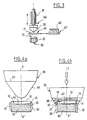
- Figure 3 illustrates the principle of such an installation for implementing the invention allowing the simultaneous marking of one of the sides and edge of a game token shaped disc or similar object.
- the reference 30 represents a horizontal base intended to serve as support token 10 with full straight edge.
- An ink pad 34 is mounted on a frame 31 so as to be movable according to alternative vertical movements.
- Stamp 34 has a deformable head 36 with axial axis symmetry ZZ 'made of synthetic material (e.g. rubber silicone synthetic with a Shore A hardness of order of 6), in this case conical tip 38.
- the deformable head 36 is adapted to wedge on face 12 and edge 16 of token 10 when marking the right edge 14.
- a plate holder 40 carrying a plane ink plate 11 integrating the image of a slice decoration (for example the image decoration 22 illustrated in Figure 2) is likely to reciprocating movements between the buffer 34 vertical (position 40) and the vertical of an ink tank 42 (position 40 ').
- the pad printing operation properly said is carried out in the following manner. After inking the plate 11 (position 40 ') the plate holder is moved in the position 40 coaxial with the buffer 34 so as to arrange the area in the form of a crown 20 of plate 11 coaxial with pad 34.
- a first vertical movement descending from buffer 34 makes it possible to recover the ink by one touch.
- the buffer 34 After raising buffer 34 and removing of the plate holder (towards position 40 '), the buffer 34 undergoes a second vertical downward movement to deposit the ink by pressing first on side 12 of the token 10 then, by greater deformation of the head of pad 36, on edge 14.
- the final decor is constituted by complementarity and / or superposition of monochrome decorations, each of these intermediate decorations being engraved on separate plates.
- multi-color marking i.e. several plate holders mobile or a series of pad printing units monochrome associated with a mobile token holder base.
- the ink plates are engraved with a depth between 18 and 20 ⁇ m. otherwise the various types of inks and / or varnishes suitable for pad printing can be used, in particular inks revealable in UV rays for discreet markings (e.g. for identification numbers and / or token coding).
- the token is centered on the ZZ 'axis of the buffer by retractable vertical centering slides 32 to curved internal walls complementary to section 14 of the token 10 and mounted in axial sliding on the around the base 30.
- This centering operation prior to the marking itself or in phase initial marking is important for good position the token 10 relative to the buffer 34, especially in this case so that the edge 16 matches well with its inked image on the tip conical 38 of buffer 34.
- the sliders of centering 32 gradually retract (by through any mechanical arrangement known) to allow the head 36 of the pad 34 to deform along edge 14 by wedging on the edge 16 (the latter being sufficiently clear to avoid unwanted slippage from the face 12 at the level of the ridge) until the anchoring of the section 14 when the end 38 (conical at rest) of the deformable head 36 of pad 34 is compressed (with a slight protrusion of the rim of the head 36 beyond the plane of the edge 17 of the lower face 13 of the token 10).
- the token 10 is provided means for holding the token 10 in place on its base 30, by example at least one adhesive pad 42 fixed to the base 30, the pad 42 being in contact with the face lower 13 of the token 10 resting on the base 30, and / or partial vacuum aspiration (not shown).
- at least one adhesive pad 42 fixed to the base 30, the pad 42 being in contact with the face lower 13 of the token 10 resting on the base 30, and / or partial vacuum aspiration (not shown).
- the use of one or several pads 42 providing sufficient adhesion to ensure, once the token is centered by the sliders 32, keeping the token in place during marking the token, allows to retract slides 32 even before marking the token well said.
- the slides 32 can be replaced by a retractable ring (not shown) mounted on the periphery of the token base.
- the pad 34 has a deformable head 36 with a substantially conical tip and having a diameter working Dt at least equal to the diameter of the token increased the token height by five times, for example a minimum diameter Dt of 55 mm for the token 10 40 mm in diameter and edge height 3.3 mm.
- the invention is of course usable with other types of stamp of various shape and hardness chosen in the standard ranges of manufacturers. Among these one can cite buffers of cylindrical shape with tip convex whose diameter Dt meets the above criterion.
- the invention applies also with tokens with softened edges and comprising a central straight edge extending substantially over a significant portion of the token thickness and related to two sides of it by two transition zones ( small rounded or enlarged chamfer).
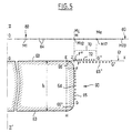
- token 60 shown diagrammatically at Figure 5 shows a diameter of 40 mm for a total slice height of 3.3 mm, of which approximately 2.5 mm right central slice and two rounds of radius transition between 0.4 and 0.5 mm (with a theoretical radius to the injection mold of 0.5 mm).
- the invention as described under non-limiting example for token 10 at full straight edge especially marking operations proper and its various variants, the marking device and its variants, the various stamps, the general principle of preparing snapshots by flap on the reference plane and contraction radial of the intermediate decoration and variations of engravings of clichés, is also applicable to the slice token central right, in particular with token 60 illustrated in figure 5.
- the softened edge of the token results in a sliding of the pad at the softened edge often making necessary a correction in the placement of the edge internal image bearing crown and possibly the contraction coefficient K. So generally the internal edge of the crown 70 bearer of the image-decoration is close to the center ⁇ of token.
- the right edge of the token 60 is constituted by a central straight edge 64 (consisting of a surface cylindrical with axis ZZ 'perpendicular to the Pref plane, projecting on the latter according to a circle of radius OJ, and represented by the FG segment) and two areas of transition, in this case two rounding 66 and 66 '(made up of shaped surfaces of revolution general of spherical crown or cone and represented by the quarter circles EF and GH, the point H being the equivalent on the other face 63 of the token 60 of point E of face 62).
- the position of the internal circular edge of the crown 70 and the contraction coefficient K of the radial transformation are determined, for a given model of token with a straight edge (for example the token 60 with edge profile EFGH) and a given buffer, by marking the token model with the aid of an inking positioning plate 80 centered on the axis of the token ZZ 'and carrying a test pattern 82 to close concentric circles.
- the test pattern 82 is in the form of a crown of center ⁇ and the mean radius OM of which is chosen to be close to or equal to the radius OJ of the token model and the width of the order of 2 times the height h of the token.
- the test pattern 82 used for the token 60 has 23 close concentric circles 84 numbered from M1 to M23 and in this case spaced 0.3 mm apart for a test pattern width of the order of 7 mm.
- the target has segments (not shown) of 64 rays equally distributed and crossing the concentric circles 84 to assess the lateral enlargement of the image decoration with the distance to the center ⁇ and to detect possible lateral shifts of the buffer.
- the positioning plate 80 is used to mark the right edge of the model of the token 60.
- the marking by pad printing of the central right edge of the token 60 is obtained by the use already described of the device illustrated in Figures 3, 4a and 4b (the token 60 replacing the token 10).
Landscapes
- Printing Methods (AREA)
- Auxiliary Devices For And Details Of Packaging Control (AREA)
- Absorbent Articles And Supports Therefor (AREA)
- Image Analysis (AREA)
- Pinball Game Machines (AREA)
- Dot-Matrix Printers And Others (AREA)
- Inks, Pencil-Leads, Or Crayons (AREA)
- Labeling Devices (AREA)
- Control Of Vending Devices And Auxiliary Devices For Vending Devices (AREA)
Description
- la figure 1 représente une vue en perspective d'un jeton de jeu à pleine tranche droite avec décor de tranche;
- la figure 2 représente une vue de face du cliché encreur utilisé pour réaliser le décor de tranche du jeton de la figure 1 selon le procédé de l'invention;
- la figure 3 représente le schéma de principe d'une installation de tampographie permettant la mise en oeuvre du procédé de l'invention;
- les figures 4a et 4b représentent une opération de marquage par tampographie de la tranche d'un jeton de jeu à tranche droite à l'aide du dispositif illustré à la figure 3; et
- la figure 5 représente une vue schématique en coupe agrandie d'un jeton de jeu à tranche droite centrale et du cliché encreur correspondant utilisé pour réaliser le décor de la tranche droite du jeton selon le procédé de l'invention.
- soit un cliché encreur comportant un décor-image de face tramé (par exemple à 130 points au pouce) et un décor-image de tranche non tramé ;
- soit un cliché encreur comportant un décor-image d'une face du jeton et un décor-image de tranche à gravure approfondie, la gravure du décor-image de tranche (de l'ordre de 25 µm) étant alors plus profonde que la gravure du décor-image de la face du jeton (de l'ordre de 18 µm). Un tel cliché est obtenu par l'utilisation d'un masque approprié.
Bien entendu le marquage par tampographie de la tranche droite centrale du jeton 60 est obtenu par l'utilisation déjà décrite du dispositif illustré sur les figures 3, 4a et 4b (le jeton 60 remplaçant le jeton 10).
Claims (16)
- Procédé de marquage par tampographie de la tranche (14,64) d'un jeton de jeu (10,60) en forme de disque à tranche droite ou d'un objet de forme analogue, caractérisé par l'utilisation d'un tampon encré (34) déplacé coaxialement audit jeton (10,60) en association avec un cliché encreur plan (11,61) comportant une zone en forme de couronne (20,70) adaptée pour être disposée coaxialement au tampon (34) et porteuse d'un décor-image (22,72) défini par une représentation radialement déformée du décor (15,65) de la tranche droite (14,64) du jeton (10,60).
- Procédé selon la revendication 1, caractérisé en ce que le décor-image (22) est obtenu par la combinaison d'une opération de rabat radial de la tranche (14) du jeton autour d'une arête faciale (16) incluse dans le plan du cliché encreur (11) et d'une opération de contraction du décor vers ladite arête faciale (16), l'ordre séquentiel des deux opérations étant indifférent.
- Procédé selon la revendication 1, caractérisé en ce que le décor-image (22,72) est obtenu, à partir d'un décor intermédiaire (15',65') réalisé par rabat radial du décor de tranche (15,65) dans un plan de référence (Préf) correspondant au plan du cliché encreur (11,61) et comportant une (12,62) des faces du jeton, face ci-après désignée face de référence, par une transformation radiale de contraction du décor intermédiaire (15',65') dans le plan de référence vers le centre de la couronne (20,70) porteuse du décor-image.
- Procédé selon la revendication 3, caractérisé en ce que la position du bord circulaire interne de la couronne (20,70) et le coefficient de contraction de la transformation radiale sont déterminés, pour un modèle donné de jeton à tranche droite et un tampon donné, par marquage du modèle de jeton à l'aide d'un cliché encreur de positionnement (80) centré sur l'axe ZZ' du jeton (60) et porteur d'une mire (82) à cercles concentriques rapprochés (84).
- Procédé selon l'une des revendications 3 et 4, caractérisé en ce que les caractéristiques de la transformation radiale de contraction sont choisies pour obtenir une réduction de la hauteur radiale du décor intermédiaire (15',65') comprise entre 25 et 40%, soit un coefficient de contraction radiale compris entre 0,75 et 0,6.
- Procédé selon l'une des revendications 3 à 5 utilisé pour le marquage de jetons à pleine tranche droite, caractérisé en ce que le bord circulaire interne de la couronne (20) correspond sensiblement à l'arête (16) de la face de référence (12) du jeton, arête ci-après désignée arête de référence.
- Procédé selon la revendication 6, caractérisé en ce que la transformation radiale de contraction utilise pour origine relative sur chaque rayon OR le point correspondant A de l'arête de référence (16).
- Procédé selon l'une des revendications 3 à 5 utilisé pour le marquage de jetons à tranche droite centrale, caractérisé en ce que le bord circulaire interne de la couronne (70) correspond sensiblement au cercle de projection axiale de la tranche droite (64) sur la face de référence (62) du jeton.
- Procédé selon l'une des revendications précédentes, caractérisé par l'utilisation d'un tampon déformable à symétrie axiale (34) d'un diamètre (Dt) au moins égal au diamètre du jeton (10,60) augmenté d'environ cinq fois la hauteur de la tranche du jeton.
- Procédé selon l'une des revendications précédentes, caractérisé en ce que le cliché encreur (11,61) comporte un décor-image tramé d'une face du jeton et un décor-image de tranche non tramé.
- Procédé selon l'une des revendications 1 à 9, caractérisé en ce que le cliché encreur (11,61) comporte un décor-image d'une face du jeton et un décor-image de tranche, la gravure du décor-image de tranche étant plus profonde que la gravure du décor-image de la face du jeton.
- Dispositif de tampographie adapté pour la mise en oeuvre du procédé de marquage selon l'une des revendications précédentes, caractérisé en ce qu'il comporte un socle (30) pour le jeton (10), ledit socle (30) étant équipé de moyens de centrage (32) du jeton coaxialement audit tampon avant l'opération de marquage de tranche par tampographie, lesdits moyens de centrage (32) étant escamotables pour permettre le marquage de la tranche (14) du jeton lors du déplacement du tampon.
- Dispositif selon la revendication 12, caractérisé en ce que lesdits moyens de centrage (32) sont progressivement escamotables avec le déplacement du tampon lors de l'opération de marquage de la tranche (14) du jeton.
- Dispositif selon l'une des revendications 12 à 13, caractérisé en ce que les moyens de centrage escamotables du type à coulisseaux (32) ou à anneau de centrage sont montés en coulissement axial sur le pourtour du socle (30).
- Dispositif selon l'une des revendications 12 à 14, caractérisé en ce qu'il comporte des moyens de maintien en place du jeton (10) sur le socle (30), notamment lors du relevage du tampon.
- Dispositif selon la revendication 15, caractérisé en ce que lesdits moyens de maintien en place du jeton (10) sont constitués par au moins une pastille adhésive (42) en contact avec la face (13) du jeton en appui sur le socle (30) et/ou par une aspiration sous vide.
Applications Claiming Priority (3)
| Application Number | Priority Date | Filing Date | Title |
|---|---|---|---|
| FR9703872 | 1997-03-28 | ||
| FR9703872A FR2761297B1 (fr) | 1997-03-28 | 1997-03-28 | Procede de marquage par tampographie d'un jeton de jeu et dispositif de mise en oeuvre du procede |
| PCT/FR1998/000485 WO1998043816A1 (fr) | 1997-03-28 | 1998-03-11 | Procede de marquage par tampographie d'un jeton de jeu et dispositif de mise en oeuvre du procede |
Publications (2)
| Publication Number | Publication Date |
|---|---|
| EP0973642A1 EP0973642A1 (fr) | 2000-01-26 |
| EP0973642B1 true EP0973642B1 (fr) | 2002-05-15 |
Family
ID=9505323
Family Applications (1)
| Application Number | Title | Priority Date | Filing Date |
|---|---|---|---|
| EP98913882A Expired - Lifetime EP0973642B1 (fr) | 1997-03-28 | 1998-03-11 | Procede de marquage par tampographie d'un jeton de jeu et dispositif de mise en oeuvre du procede |
Country Status (11)
| Country | Link |
|---|---|
| US (2) | US6176185B1 (fr) |
| EP (1) | EP0973642B1 (fr) |
| AT (1) | ATE217579T1 (fr) |
| AU (1) | AU6841498A (fr) |
| CA (1) | CA2256551C (fr) |
| DE (1) | DE69805405T2 (fr) |
| ES (1) | ES2176998T3 (fr) |
| FR (1) | FR2761297B1 (fr) |
| PT (1) | PT973642E (fr) |
| WO (1) | WO1998043816A1 (fr) |
| ZA (1) | ZA982598B (fr) |
Cited By (1)
| Publication number | Priority date | Publication date | Assignee | Title |
|---|---|---|---|---|
| CN101374663B (zh) * | 2006-02-03 | 2010-07-28 | Itw莫洛克有限公司 | 油墨移印系统 |
Families Citing this family (24)
| Publication number | Priority date | Publication date | Assignee | Title |
|---|---|---|---|---|
| US20030174864A1 (en) * | 1997-10-27 | 2003-09-18 | Digital Biometrics, Inc. | Gambling chip recognition system |
| US6532297B1 (en) * | 1995-10-05 | 2003-03-11 | Digital Biometrics, Inc. | Gambling chip recognition system |
| FR2761297B1 (fr) | 1997-03-28 | 1999-05-21 | Bourgogne Grasset | Procede de marquage par tampographie d'un jeton de jeu et dispositif de mise en oeuvre du procede |
| BE1013128A6 (nl) * | 1999-09-21 | 2001-10-02 | Volder L De | Inrichting voor het bedrukken van voorwerpen van het type tabletten, in het bijzonder medische tabletten. |
| DE10003412A1 (de) * | 2000-01-27 | 2001-08-02 | Hermann Lutz | Verfahren zur Verschönerung/Veredelung eines dreidimensionalen Rings aus Holz, Holzwerkstoff oder Kunststoff, sowie einen mit diesem Verfahren veredelten Ring |
| FR2805067B1 (fr) * | 2000-02-15 | 2003-09-12 | Bourgogne Grasset | Jeton a puce electronique et procedes de fabrication d'un tel jeton |
| FR2825661B1 (fr) * | 2001-06-06 | 2006-11-24 | Bourgogne Grasset | Dispositif de pose pour jeton et installations de tampographie incorporant de tels dispositifs |
| FR2833102B1 (fr) * | 2001-12-03 | 2004-02-27 | Bourgogne Grasset | Dispositif de rangement electronique pour jetons de jeu |
| US20030218299A1 (en) * | 2002-05-22 | 2003-11-27 | The Bud Jones Company, Inc. | Method of manufacturing gaming dice and die made thereby |
| FR2842456B1 (fr) | 2002-07-22 | 2004-12-24 | Bourgogne Grasset | Procede de marquage par tampographie et sublimation et encres de tampographie sublimables |
| FR2854972B1 (fr) * | 2003-05-12 | 2005-07-15 | Bourgogne Grasset | Poste de lecture et/ou d'ecriture pour jetons de jeu electroniques |
| WO2006106192A1 (fr) * | 2005-04-07 | 2006-10-12 | Gaming Partners International | Procede de gestion d'une pluralite de lecteurs de jetons a puce electronique et equipements de mise en oeuvre dudit procede. |
| FR2888372B1 (fr) * | 2005-07-08 | 2007-10-12 | Caming Partners Internationale | Jeton a puce electronique et son procede de fabrication |
| EP1946252B1 (fr) * | 2005-11-09 | 2012-08-08 | Gaming Partners International | Jeton a insert a puce electronique |
| CA2614291C (fr) * | 2007-05-25 | 2015-02-17 | Gaming Partners International | Jeton avec dispositif electronique |
| AU2008252054A1 (en) * | 2007-12-18 | 2009-07-02 | Aristocrat Technologies Australia Pty Limited | A gaming machine and a network of gaming machines |
| KR101435552B1 (ko) * | 2010-03-12 | 2014-08-29 | 가부시키가이샤 미마키 엔지니어링 | 화상 형성 장치 및 화상 형성 방법 |
| CN103753948B (zh) * | 2012-05-09 | 2016-08-17 | 南京乐金熊猫电器有限公司 | 移印装置 |
| CN106696452B (zh) * | 2017-01-03 | 2022-09-27 | 深圳市裕同包装科技股份有限公司 | 模切上色一体化设备及对纸张进行模切和上色的加工方法 |
| CN106541698B (zh) * | 2017-01-03 | 2019-01-11 | 深圳市裕同包装科技股份有限公司 | 一种侧边自动上色的印刷装置及其操作方法 |
| EP3598920A1 (fr) * | 2018-07-26 | 2020-01-29 | Trisa Holding AG | Étiquetage / impression d'éléments d'application et / ou de nettoyage |
| KR102077520B1 (ko) * | 2019-07-17 | 2020-02-14 | (주)피에스산업 | 디스플레이 패널 측면단자 인쇄 시스템 |
| KR20210011524A (ko) * | 2019-07-22 | 2021-02-02 | 삼성디스플레이 주식회사 | 패드 인쇄 장치 |
| US11717728B1 (en) * | 2022-02-28 | 2023-08-08 | Acushnet Company | Golf ball having markings spaced from a centerline plane |
Family Cites Families (12)
| Publication number | Priority date | Publication date | Assignee | Title |
|---|---|---|---|---|
| US2748696A (en) * | 1951-06-13 | 1956-06-05 | Murray Lilian | Printing or decoration of ceramic or other ware |
| GB1432355A (en) * | 1972-07-29 | 1976-04-14 | Service Eng Ltd | Pritning machines |
| US4019436A (en) * | 1976-06-16 | 1977-04-26 | Martin Handweiler | Technique for producing a pre-distorted design format for use in transfer printing |
| FR2463683A1 (fr) * | 1979-08-23 | 1981-02-27 | Essilor Int | Tampon de transfert pour impression de monture de lunettes |
| JPS6030344A (ja) * | 1983-07-29 | 1985-02-15 | M G:Kk | キ−トツプの製造方法 |
| ES8703346A1 (es) * | 1985-07-31 | 1987-03-01 | Unice Sa | Sistema para la impresion tampografica de cuerpos esfericos y similares |
| JP2838203B2 (ja) * | 1987-05-13 | 1998-12-16 | 一兄 加藤 | 碗状物品の絵付方法及びその装置 |
| US5165340A (en) | 1991-03-06 | 1992-11-24 | Karlyn William M | Multicolor printing system for the silk-screen printing of compact discs |
| IT1257500B (it) | 1992-07-31 | 1996-01-25 | Macchina per la stampa offset di oggetti piani, ed in particolare per compact disc | |
| FR2730392B1 (fr) * | 1995-02-15 | 1997-03-14 | Bourgogne Grasset | Jeton de jeu et procede de marquage d'un tel jeton |
| FR2761297B1 (fr) | 1997-03-28 | 1999-05-21 | Bourgogne Grasset | Procede de marquage par tampographie d'un jeton de jeu et dispositif de mise en oeuvre du procede |
| DE19803617C1 (de) | 1998-01-30 | 1999-08-05 | Kammann Maschf Werner | Vorrichtung zum Dekorieren von Objekten |
-
1997
- 1997-03-28 FR FR9703872A patent/FR2761297B1/fr not_active Expired - Fee Related
-
1998
- 1998-03-11 US US09/147,253 patent/US6176185B1/en not_active Expired - Fee Related
- 1998-03-11 ES ES98913882T patent/ES2176998T3/es not_active Expired - Lifetime
- 1998-03-11 AT AT98913882T patent/ATE217579T1/de not_active IP Right Cessation
- 1998-03-11 DE DE69805405T patent/DE69805405T2/de not_active Expired - Lifetime
- 1998-03-11 AU AU68414/98A patent/AU6841498A/en not_active Abandoned
- 1998-03-11 PT PT98913882T patent/PT973642E/pt unknown
- 1998-03-11 EP EP98913882A patent/EP0973642B1/fr not_active Expired - Lifetime
- 1998-03-11 CA CA002256551A patent/CA2256551C/fr not_active Expired - Fee Related
- 1998-03-11 WO PCT/FR1998/000485 patent/WO1998043816A1/fr not_active Ceased
- 1998-03-27 ZA ZA982598A patent/ZA982598B/xx unknown
-
2000
- 2000-08-15 US US09/638,031 patent/US6467413B1/en not_active Expired - Lifetime
Cited By (1)
| Publication number | Priority date | Publication date | Assignee | Title |
|---|---|---|---|---|
| CN101374663B (zh) * | 2006-02-03 | 2010-07-28 | Itw莫洛克有限公司 | 油墨移印系统 |
Also Published As
| Publication number | Publication date |
|---|---|
| CA2256551C (fr) | 2006-08-29 |
| CA2256551A1 (fr) | 1998-10-08 |
| ES2176998T3 (es) | 2002-12-01 |
| ZA982598B (en) | 1998-04-15 |
| US6176185B1 (en) | 2001-01-23 |
| FR2761297B1 (fr) | 1999-05-21 |
| US6467413B1 (en) | 2002-10-22 |
| WO1998043816A1 (fr) | 1998-10-08 |
| PT973642E (pt) | 2002-09-30 |
| FR2761297A1 (fr) | 1998-10-02 |
| DE69805405T2 (de) | 2003-01-09 |
| EP0973642A1 (fr) | 2000-01-26 |
| ATE217579T1 (de) | 2002-06-15 |
| DE69805405D1 (de) | 2002-06-20 |
| AU6841498A (en) | 1998-10-22 |
Similar Documents
| Publication | Publication Date | Title |
|---|---|---|
| CA2256551C (fr) | Procede de marquage par tampographie d'un jeton de jeu et dispositif de mise en oeuvre du procede | |
| FR2730392A1 (fr) | Jeton de jeu et procede de marquage d'un tel jeton | |
| EP3137289B1 (fr) | Element de moule pour moule de pneumatique comportant un marquage | |
| CN100453338C (zh) | 防伪装置 | |
| EP0619192A1 (fr) | Plaque d'impression | |
| FR3085304A1 (fr) | Forme imprimante photosensible pour un procede d’impression flexographique comprenant des informations visibles et non imprimables, procede de preparation d’une telle forme imprimante | |
| EP1392511B1 (fr) | Dispositifs de pose pour jeton et installations de tampographie incorporant de tels dispositifs | |
| EP0794056B1 (fr) | Procédé et machine d'impression pour la mise en oeuvre du procédé et support ainsi imprimé | |
| US10710389B2 (en) | Can imprinting device and associated methods | |
| CA2304591A1 (fr) | Procede de fabrication et de reproduction d'au moins une partie d'un objet ou d'un individu | |
| EP3894239B1 (fr) | Pneumatique pourvu d'un marquage colore et d'une texture sur un flanc | |
| EP1446275B1 (fr) | Moule pour pneus | |
| EP1778436B1 (fr) | Tampon et dispositif de tamponnage de verres ophtalmiques et procede de tamponnage | |
| WO2019115299A1 (fr) | Procede de personnalisation / marquage d'une carte a puce | |
| FR2986464A1 (fr) | Procede et installation de decoration d'un objet, de type flacon de verre, et flacon de verre obtenu | |
| EP3748608B1 (fr) | Dispositif de lecture tactile pour l identification des couleurs | |
| WO2019229387A1 (fr) | Pneumatique pourvu d'un marquage coloré et d'une texture sur un flanc | |
| FR2853855A1 (fr) | Outil de mise en forme ou de decoupe et plaque realisee grace a un tel outil | |
| EP2843595B1 (fr) | Adaptateur pour carte à microcircuit entre un grand format et un petit format de moindre épaisseur | |
| FR3055054B1 (fr) | Dispositif multicouche imprimable a puce electronique, et son procede de fabrication | |
| FR2874347A1 (fr) | Dispositif de decoupe d'une etiquette dans une feuille decoree, procede de mise en oeuvre et kit de fabrication d'etiquettes adhesives notamment pour cederom | |
| FR2595987A1 (fr) | Procede d'encrage pour caches grattables | |
| FR2773721A1 (fr) | De a jouer | |
| EP2810760A2 (fr) | Procédé de fabrication d'inserts de moules difficilement reproductibles, inserts et pièces plastiques fabriquées selon ce procédé | |
| FR2939898A1 (fr) | Fond de cadran avec effet de moire |
Legal Events
| Date | Code | Title | Description |
|---|---|---|---|
| PUAI | Public reference made under article 153(3) epc to a published international application that has entered the european phase |
Free format text: ORIGINAL CODE: 0009012 |
|
| 17P | Request for examination filed |
Effective date: 19990710 |
|
| AK | Designated contracting states |
Kind code of ref document: A1 Designated state(s): AT BE CH DE DK ES FI FR GB GR IE IT LI LU MC NL PT SE |
|
| RIC1 | Information provided on ipc code assigned before grant |
Free format text: 7B 41F 17/00 A, 7A 44C 21/00 B |
|
| GRAG | Despatch of communication of intention to grant |
Free format text: ORIGINAL CODE: EPIDOS AGRA |
|
| 17Q | First examination report despatched |
Effective date: 20010523 |
|
| GRAG | Despatch of communication of intention to grant |
Free format text: ORIGINAL CODE: EPIDOS AGRA |
|
| GRAH | Despatch of communication of intention to grant a patent |
Free format text: ORIGINAL CODE: EPIDOS IGRA |
|
| GRAH | Despatch of communication of intention to grant a patent |
Free format text: ORIGINAL CODE: EPIDOS IGRA |
|
| GRAA | (expected) grant |
Free format text: ORIGINAL CODE: 0009210 |
|
| AK | Designated contracting states |
Kind code of ref document: B1 Designated state(s): AT BE CH DE DK ES FI FR GB GR IE IT LI LU MC NL PT SE |
|
| PG25 | Lapsed in a contracting state [announced via postgrant information from national office to epo] |
Ref country code: IE Free format text: LAPSE BECAUSE OF FAILURE TO SUBMIT A TRANSLATION OF THE DESCRIPTION OR TO PAY THE FEE WITHIN THE PRESCRIBED TIME-LIMIT Effective date: 20020515 Ref country code: FI Free format text: LAPSE BECAUSE OF FAILURE TO SUBMIT A TRANSLATION OF THE DESCRIPTION OR TO PAY THE FEE WITHIN THE PRESCRIBED TIME-LIMIT Effective date: 20020515 |
|
| REF | Corresponds to: |
Ref document number: 217579 Country of ref document: AT Date of ref document: 20020615 Kind code of ref document: T |
|
| REG | Reference to a national code |
Ref country code: GB Ref legal event code: FG4D Free format text: NOT ENGLISH Ref country code: CH Ref legal event code: EP |
|
| REG | Reference to a national code |
Ref country code: IE Ref legal event code: FG4D Free format text: FRENCH |
|
| REF | Corresponds to: |
Ref document number: 69805405 Country of ref document: DE Date of ref document: 20020620 |
|
| REG | Reference to a national code |
Ref country code: CH Ref legal event code: NV Representative=s name: BOVARD AG PATENTANWAELTE |
|
| GBT | Gb: translation of ep patent filed (gb section 77(6)(a)/1977) |
Effective date: 20020720 |
|
| PG25 | Lapsed in a contracting state [announced via postgrant information from national office to epo] |
Ref country code: SE Free format text: LAPSE BECAUSE OF FAILURE TO SUBMIT A TRANSLATION OF THE DESCRIPTION OR TO PAY THE FEE WITHIN THE PRESCRIBED TIME-LIMIT Effective date: 20020815 Ref country code: DK Free format text: LAPSE BECAUSE OF FAILURE TO SUBMIT A TRANSLATION OF THE DESCRIPTION OR TO PAY THE FEE WITHIN THE PRESCRIBED TIME-LIMIT Effective date: 20020815 |
|
| REG | Reference to a national code |
Ref country code: PT Ref legal event code: SC4A Free format text: AVAILABILITY OF NATIONAL TRANSLATION Effective date: 20020712 |
|
| REG | Reference to a national code |
Ref country code: ES Ref legal event code: FG2A Ref document number: 2176998 Country of ref document: ES Kind code of ref document: T3 |
|
| REG | Reference to a national code |
Ref country code: IE Ref legal event code: FD4D Ref document number: 0973642E Country of ref document: IE |
|
| PG25 | Lapsed in a contracting state [announced via postgrant information from national office to epo] |
Ref country code: LU Free format text: LAPSE BECAUSE OF NON-PAYMENT OF DUE FEES Effective date: 20030311 |
|
| PLBE | No opposition filed within time limit |
Free format text: ORIGINAL CODE: 0009261 |
|
| STAA | Information on the status of an ep patent application or granted ep patent |
Free format text: STATUS: NO OPPOSITION FILED WITHIN TIME LIMIT |
|
| 26N | No opposition filed |
Effective date: 20030218 |
|
| REG | Reference to a national code |
Ref country code: FR Ref legal event code: CD |
|
| REG | Reference to a national code |
Ref country code: CH Ref legal event code: PFA Owner name: GAMING PARTNERS INTERNATIONAL Free format text: ETABLISSEMENTS BOURGOGNE ET GRASSET#Z.I. BEAUNE-SAVIGNY, LIEUDIT LA CHAMPAGNE#21420 SAVIGNY-LES-BEAUNE (FR) -TRANSFER TO- GAMING PARTNERS INTERNATIONAL#Z.I. BEAUNE-SAVIGNY, LIEUDIT LA CHAMPAGNE#21420 SAVIGNY-LES-BEAUNE (FR) |
|
| NLT1 | Nl: modifications of names registered in virtue of documents presented to the patent office pursuant to art. 16 a, paragraph 1 |
Owner name: GAMING PARTNERS INTERNATIONAL |
|
| REG | Reference to a national code |
Ref country code: PT Ref legal event code: PD4A Owner name: GAMING PARTNERS INTERNATIONAL, FR Effective date: 20050607 |
|
| REG | Reference to a national code |
Ref country code: ES Ref legal event code: PC2A |
|
| PG25 | Lapsed in a contracting state [announced via postgrant information from national office to epo] |
Ref country code: GR Free format text: LAPSE BECAUSE OF NON-PAYMENT OF DUE FEES Effective date: 20020515 |
|
| PGFP | Annual fee paid to national office [announced via postgrant information from national office to epo] |
Ref country code: PT Payment date: 20100218 Year of fee payment: 13 Ref country code: MC Payment date: 20100222 Year of fee payment: 13 Ref country code: ES Payment date: 20100323 Year of fee payment: 13 Ref country code: CH Payment date: 20100315 Year of fee payment: 13 |
|
| PGFP | Annual fee paid to national office [announced via postgrant information from national office to epo] |
Ref country code: IT Payment date: 20100325 Year of fee payment: 13 |
|
| PGFP | Annual fee paid to national office [announced via postgrant information from national office to epo] |
Ref country code: GB Payment date: 20100225 Year of fee payment: 13 Ref country code: AT Payment date: 20100217 Year of fee payment: 13 |
|
| PGFP | Annual fee paid to national office [announced via postgrant information from national office to epo] |
Ref country code: FR Payment date: 20100416 Year of fee payment: 13 |
|
| PGFP | Annual fee paid to national office [announced via postgrant information from national office to epo] |
Ref country code: NL Payment date: 20100218 Year of fee payment: 13 Ref country code: DE Payment date: 20100315 Year of fee payment: 13 |
|
| PGFP | Annual fee paid to national office [announced via postgrant information from national office to epo] |
Ref country code: BE Payment date: 20100505 Year of fee payment: 13 |
|
| REG | Reference to a national code |
Ref country code: CH Ref legal event code: PFA Owner name: GAMING PARTNERS INTERNATIONAL Free format text: GAMING PARTNERS INTERNATIONAL#Z.I. BEAUNE-SAVIGNY, LIEUDIT LA CHAMPAGNE#21420 SAVIGNY-LES-BEAUNE (FR) -TRANSFER TO- GAMING PARTNERS INTERNATIONAL#Z.I. BEAUNE-SAVIGNY, LIEUDIT LA CHAMPAGNE#21420 SAVIGNY-LES-BEAUNE (FR) |
|
| REG | Reference to a national code |
Ref country code: PT Ref legal event code: MM4A Free format text: LAPSE DUE TO NON-PAYMENT OF FEES Effective date: 20110912 |
|
| BERE | Be: lapsed |
Owner name: *GAMING PARTNERS INTERNATIONAL Effective date: 20110331 |
|
| REG | Reference to a national code |
Ref country code: NL Ref legal event code: V1 Effective date: 20111001 |
|
| PG25 | Lapsed in a contracting state [announced via postgrant information from national office to epo] |
Ref country code: PT Free format text: LAPSE BECAUSE OF NON-PAYMENT OF DUE FEES Effective date: 20110912 Ref country code: MC Free format text: LAPSE BECAUSE OF NON-PAYMENT OF DUE FEES Effective date: 20110331 |
|
| REG | Reference to a national code |
Ref country code: CH Ref legal event code: PL |
|
| GBPC | Gb: european patent ceased through non-payment of renewal fee |
Effective date: 20110311 |
|
| PG25 | Lapsed in a contracting state [announced via postgrant information from national office to epo] |
Ref country code: AT Free format text: LAPSE BECAUSE OF NON-PAYMENT OF DUE FEES Effective date: 20110311 |
|
| REG | Reference to a national code |
Ref country code: FR Ref legal event code: ST Effective date: 20111130 |
|
| PG25 | Lapsed in a contracting state [announced via postgrant information from national office to epo] |
Ref country code: BE Free format text: LAPSE BECAUSE OF NON-PAYMENT OF DUE FEES Effective date: 20110331 |
|
| PG25 | Lapsed in a contracting state [announced via postgrant information from national office to epo] |
Ref country code: CH Free format text: LAPSE BECAUSE OF NON-PAYMENT OF DUE FEES Effective date: 20110331 Ref country code: NL Free format text: LAPSE BECAUSE OF NON-PAYMENT OF DUE FEES Effective date: 20111001 Ref country code: LI Free format text: LAPSE BECAUSE OF NON-PAYMENT OF DUE FEES Effective date: 20110331 Ref country code: FR Free format text: LAPSE BECAUSE OF NON-PAYMENT OF DUE FEES Effective date: 20110331 Ref country code: DE Free format text: LAPSE BECAUSE OF NON-PAYMENT OF DUE FEES Effective date: 20111001 |
|
| PG25 | Lapsed in a contracting state [announced via postgrant information from national office to epo] |
Ref country code: GB Free format text: LAPSE BECAUSE OF NON-PAYMENT OF DUE FEES Effective date: 20110311 Ref country code: IT Free format text: LAPSE BECAUSE OF NON-PAYMENT OF DUE FEES Effective date: 20110311 |
|
| REG | Reference to a national code |
Ref country code: ES Ref legal event code: FD2A Effective date: 20120423 |
|
| REG | Reference to a national code |
Ref country code: DE Ref legal event code: R119 Ref document number: 69805405 Country of ref document: DE Effective date: 20111001 |
|
| PG25 | Lapsed in a contracting state [announced via postgrant information from national office to epo] |
Ref country code: ES Free format text: LAPSE BECAUSE OF NON-PAYMENT OF DUE FEES Effective date: 20110312 |