EP0972985A2 - Boítier de lampe à noyer dans un élément en béton, notamment dans un plafond en béton - Google Patents
Boítier de lampe à noyer dans un élément en béton, notamment dans un plafond en béton Download PDFInfo
- Publication number
- EP0972985A2 EP0972985A2 EP99108885A EP99108885A EP0972985A2 EP 0972985 A2 EP0972985 A2 EP 0972985A2 EP 99108885 A EP99108885 A EP 99108885A EP 99108885 A EP99108885 A EP 99108885A EP 0972985 A2 EP0972985 A2 EP 0972985A2
- Authority
- EP
- European Patent Office
- Prior art keywords
- housing
- closure element
- luminaire
- lamp housing
- housing according
- Prior art date
- Legal status (The legal status is an assumption and is not a legal conclusion. Google has not performed a legal analysis and makes no representation as to the accuracy of the status listed.)
- Ceased
Links
Images


Classifications
-
- E—FIXED CONSTRUCTIONS
- E04—BUILDING
- E04G—SCAFFOLDING; FORMS; SHUTTERING; BUILDING IMPLEMENTS OR AIDS, OR THEIR USE; HANDLING BUILDING MATERIALS ON THE SITE; REPAIRING, BREAKING-UP OR OTHER WORK ON EXISTING BUILDINGS
- E04G15/00—Forms or shutterings for making openings, cavities, slits, or channels
- E04G15/06—Forms or shutterings for making openings, cavities, slits, or channels for cavities or channels in walls of floors, e.g. for making chimneys
- E04G15/061—Non-reusable forms
-
- F—MECHANICAL ENGINEERING; LIGHTING; HEATING; WEAPONS; BLASTING
- F21—LIGHTING
- F21V—FUNCTIONAL FEATURES OR DETAILS OF LIGHTING DEVICES OR SYSTEMS THEREOF; STRUCTURAL COMBINATIONS OF LIGHTING DEVICES WITH OTHER ARTICLES, NOT OTHERWISE PROVIDED FOR
- F21V21/00—Supporting, suspending, or attaching arrangements for lighting devices; Hand grips
- F21V21/02—Wall, ceiling, or floor bases; Fixing pendants or arms to the bases
- F21V21/04—Recessed bases
Definitions
- the invention relates to a lamp housing for installation in a concrete component, especially in a Concrete ceiling, for receiving at least one recessed light, such as downlight or the like, and from where appropriate control gear assigned to the recessed luminaire, e.g. from a transformer, with an insertion opening for the recessed luminaire against a formwork for the concrete component Closure element.
- Luminaire housings of this type are widely used and are used in particular when building new buildings.
- the concrete components are Components made of so-called in-situ concrete, i.e. the component is boarded, reinforced and then shed.
- the relatively large-volume luminaire housing is in Everyday operation on a construction site through the rough work exposed to raw treatment. Lateral can be attached to the lamp housing Powers, for example due to carelessness Kicks, but also horizontal forces work when Workers walk over the lamp housing. Also at Heavy armouring movements can be large Forces are exerted on the lamp housing. Not Finally, there is a risk that when pouring the Concrete the luminaire housing, due to large buoyancy forces, floats up. Because of the above Forces can therefore shift Luminaire housing come. After curing the Under certain circumstances, the luminaire housing is made of concrete offset or inclined relative to the closure element. Such an incorrect position Location of the lamp housing is with serious problems when the luminaires are later installed in the luminaire housing connected.
- the object of the invention is a lamp housing to create according to the preamble of claim 1, which the above Avoids disadvantages.
- the invention solves this problem with the features of claim 1, in particular those of the characterizing part, after which the lamp housing and the closure element detachably attached to each other are.
- the principle of the invention thus consists in essential in it, by fastening the lamp housing a shift on the closure element itself or tilting of the lamp housing relative to exclude the closure element.
- the kind of In principle, attachment is arbitrary.
- a manageable unit of luminaire housing and locking element is created, so that a common, selectable Has reference point.
- the common reference point can, for example, the formwork Be reinforcement.
- Direct attachment in the sense of Invention does not necessarily mean that the attachment is immediate.
- the lamp housing against the closure element braced is the lamp housing against the closure element braced.
- one secure sealing of the interior of the luminaire housing opposite the closure element or at the Formwork attached fastener opposite the formwork is reached. It can not be a liquid Concrete in the interior of the lamp housing reach.
- the closure element on the formwork attached and the luminaire housing is against the casing braced.
- the interior of the luminaire housing is securely sealed.
- the closure element has at least one fastening element, in particular a threaded rod, provided which with its first end on the closure element and detachable with its second end on the lamp housing is attached.
- a fastening element in particular a threaded rod
- the threaded rod the function of a load-bearing element in the manner of a support that the entire luminaire housing stabilized.
- the relative Large-volume luminaire housings are therefore more rigid. A bending of the case cover inwards is prevented if workers over the lamp housing to run. At the same time, the buoyancy forces intercepted when pouring the concrete.
- the invention is at the second end of the threaded rod a mother, especially a wing nut arranged on the outside of the case ceiling attacks.
- the wing nut is carried by the concrete enclosed and is solid after the concrete has hardened arranged. After tearing off the formwork and after loosening the closure element Threaded rod freely accessible and can from the Unscrew the thread of the wing nut.
- the fixed thread of the wing nut can now be used for fastening the recessed light or an associated one Control gear, for example a transformer, to be used. It therefore represents a particularly advantageous one Attachment point.
- luminaire housing is advantageous formed in two parts and includes an upper housing shell 11 and a lower housing shell 12.
- the lower housing shell 12 includes a grommet-like extension 13, the one insertion opening 14 for one not shown recessed luminaire to be installed later.
- the grommet-like extension 13 is via a closure element 15 inserted, which essentially is disc-shaped.
- the outside diameter D of the closure element 15 corresponds to essentially the diameter E of the insertion opening 14.
- the closure element 15 is by means of nails 16 a casing 17 for a concrete ceiling 29 (FIG. 2) attached.
- the closure element 15 has a central bore 18 on from a first end 19 one Threaded rod 20 is inserted.
- the threaded rod 20 is on the closure element by means of two nuts 21a, 21b 15 attached. It penetrates the interior 22 of the lamp housing 10 is vertical and with regard to their length to the height of the lamp housing 10 matched. She pushes through with her second End 23 a bore 24 in the ceiling 25 of the lamp housing 10.
- On the second end 23 of the threaded rod is a poultry nut 26 from the outside of the Luminaire housing 10 screwed on.
- the Assembly of the invention is brief Luminaire housing 10 described.
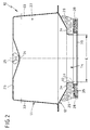
- the Formwork 17 forms the limit for one pouring concrete ceiling 29.
- the top 27 of the formwork 17 thus corresponds to the formwork after pouring and hardening of the concrete of the underside 28 (Fig. 2) of the concrete ceiling 29.
- the closure element 15 can be arranged recesses 30 for this be, for example, a position control can serve. On the other hand, you can also from the nails 16 to be attached are inserted. The Closure element 15 is then corresponding its desired position on the casing 17 pinned down.
- the threaded rod 20 is at its first end 19 before the fastening of the closure element 15 on the casing 17 with the closure element 15 firmly connected. As a result, the threaded rod 20 protrudes after nailing the closure element 15 free, 1 vertically upwards, from the casing 17 away. Now the lamp housing 10 on the Closure element 15 are placed. It takes effect the threaded rod 20 with its second end 23 the bore 24 in the ceiling 25 of the lamp housing 10. Using the wing nut 26, the lamp housing 10 now on the one hand on the closure element 15 attached and on the other hand with the free edge 31 of the grommet-like extension 13 against the casing 17 be braced.
- the lamp housing attached to the closure element 15 10 is also through the threaded rod 20 stiffened, so that external forces on the Luminaire housing 10 can be better intercepted. In particular, bending of the ceiling 25 of the Luminaire housing 10, for example by running Workers on the lamp housing 10 prevented.
- the interconnect room 32 filled.
- the entire luminaire housing 10 is thus except for through the insertion opening 14 limited area entirely of concrete surround. 2 and 4 is only in the area the insertion opening 14 concrete 29 indicated. Because of the high specific weight of liquid concrete the luminaire housing 10 tends to float, which causes significant problems in the prior art. In the luminaire housing 10 according to the invention there is a risk of floating through the threaded rod 20 diminished.
- the side wall 33 is provided the essentially cup-shaped housing upper shell 11 slightly conical to the center of the ceiling 25 of the Allow upper housing shell 11 to run. On in this way, the upper housing shell 11 effective weight of the liquid concrete used, mitigate the buoyancy.
- the plastering 35 shown in FIG. 2 is in principle not necessary.
- the free edge 31 of the grommet-like extension 13 lies in the hardened Condition of the concrete wall 29 flush on the underside 28 the concrete wall.
- a special plaster ring 36 may be useful the insertion opening 14 at least during plastering partially covers.
- the closure element 15 is approximately in the area of it Bore 18 for the threaded rod 20 slightly to the ceiling 25 of the lamp housing 10 in steps staggered. This prevents that the mother 21a with its bottom the assembly of the closure element 15 on the formwork 17 bumps against the formwork 17.
- the ceiling 25 of the Luminaire housing 10 in the area of its bore 24 for the threaded rod 20 advantageously slightly formed towards the closure element 15 offset. This serves to hold the wing nut 26 flush and is especially from Concrete ceilings 29 make sense. That way, despite a low ceiling thickness, the greatest possible volume of the interior 22 of the lamp housing 10 can be achieved. A large interior 22 can be desired if the volume of the interior 22nd of the housing 10 for cooling operating devices is provided.
- Fig. 3 shows a second embodiment of a lamp housing 10 according to the invention.
- a closure element 15 is provided, the outer diameter D is larger than the diameter E of the Insertion opening 14.
- the lamp housing 10 is not immediate braced against the formwork 17, but against the closure element 15 itself.
- the tightness of the interior 22 of the lamp housing 10 remains still guaranteed.
- This embodiment is suitable are particularly suitable for recessed lights that are flush with the bottom 28 of the concrete wall 29 should complete.
- By using such a trained Closure element 15 remains after curing a disc-shaped free space 47 of the concrete (FIG. 4), which serves to hold parts of the recessed light.
- FIGS. 3 and 4 is instead of a wing nut 26 one to the Ceiling 25 of the lamp housing 10 welded nut 37 provided.
- a luminaire housing 10 with a welded nut 37 on the closure element 15 with threaded rod attached 20 would have to the lamp housing 10 relative to the fixed Threaded rod 20 rotated about axis A. become.
- Such a construction can prove useful in certain cases.
- it can also be provided at an embodiment of FIGS. 3 and 4 a To provide wing nut 26.
- FIGS. 3 and 4 38 An annular body shown in FIGS. 3 and 4 38 is attached by means of several fastening elements 39 the lower shell 12 of the lamp housing 10 attached. It is used to attach special recessed lights and provides additional attachment points.
- the lamp housing 10 is advantageously formed in two parts, in particular the lower shell 12, as shown in the figures, insertion openings 14 with different sizes E for different sized recessed lights having.
- insertion openings 14 with different sizes E for different sized recessed lights having.
- Closure elements 15 each different Diameter D on.
- the connection between the upper housing shell 11 and Lower housing shell 12 can, for example, by
- the edges 40, 41 are flanged.
- a clamping ring not shown be provided, the free, outwardly projecting Edges 40, 41 at least partially overlap.
- the clamping ring can additionally with a closure element, for example a toggle lock be provided. It is crucial, however, that a tight connection between the two edges 40, 41 consists.
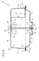
- FIG. 5 was on the representation of formwork or concrete ceiling 29 waived.
- the free Edge 40 of the lower housing shell 12 stands on this Way relative to the side wall 33 of the upper housing shell 11 partially in the interior 22 of the lamp housing 10 in front and provides holding surfaces 42 ready. On these holding surfaces 42 can easily Operating devices for the recessed light, not shown be attached.
- 42 support surfaces on the holding surfaces 43 of brackets 45 for operating devices be attached. Any is provided for this Fastening element 44, which the bracket 45 with the holding surface 42 connects.
- the bracket 45 can with its end 48 remote from the fastener 44 be attached in the area of the threaded rod 20. On this way is a particularly simple one as well as secure bracket 45 created.
- the lamp housing 10 according to the invention is particularly simple and includes conventional Components such as the threaded rod 20 and the wing nut 26.
- To assemble the lamp housing 10 on the Closure element 15 are not special tools required.
- the wing nut 26 can be done by hand be screwed.
- the threaded rod 20 created a single attachment point. So that can the assembly can be carried out relatively quickly. This means in particular a time saving compared to the prior art, where the attachment by means of Wire took a relatively long time.
- the lamp housing 10 according to the invention can basically have any cross-sectional shape.
- the cross section is preferably circular or rectangular, especially square.
- Metal especially steel.
Landscapes
- Engineering & Computer Science (AREA)
- Architecture (AREA)
- Mechanical Engineering (AREA)
- Civil Engineering (AREA)
- Structural Engineering (AREA)
- General Engineering & Computer Science (AREA)
- Non-Portable Lighting Devices Or Systems Thereof (AREA)
- Fastening Of Light Sources Or Lamp Holders (AREA)
Applications Claiming Priority (2)
| Application Number | Priority Date | Filing Date | Title |
|---|---|---|---|
| DE19832252 | 1998-07-17 | ||
| DE1998132252 DE19832252A1 (de) | 1998-07-17 | 1998-07-17 | Leuchtengehäuse für den Einbau in ein Betonbauteil, insbesondere in eine Betondecke |
Publications (2)
| Publication Number | Publication Date |
|---|---|
| EP0972985A2 true EP0972985A2 (fr) | 2000-01-19 |
| EP0972985A3 EP0972985A3 (fr) | 2000-04-12 |
Family
ID=7874456
Family Applications (1)
| Application Number | Title | Priority Date | Filing Date |
|---|---|---|---|
| EP99108885A Ceased EP0972985A3 (fr) | 1998-07-17 | 1999-05-05 | Boítier de lampe à noyer dans un élément en béton, notamment dans un plafond en béton |
Country Status (2)
| Country | Link |
|---|---|
| EP (1) | EP0972985A3 (fr) |
| DE (1) | DE19832252A1 (fr) |
Cited By (4)
| Publication number | Priority date | Publication date | Assignee | Title |
|---|---|---|---|---|
| FR2924456A1 (fr) * | 2007-12-03 | 2009-06-05 | Conception De Realisation Et D | Dispositif et procede pour former une reservation dans une dalle de beton |
| CH711488A1 (de) * | 2015-09-03 | 2017-03-15 | Firalux Holding Ag | Einbaubüchsendeckel zum Verschliessen einer Öffnung in einer Einbaubüchse. |
| EP3505707A1 (fr) * | 2017-12-27 | 2019-07-03 | Segmentum Enterprise GmbH | Appareillage ainsi que procédé de formation d'une zone fonctionnelle dans un composant d'un matériau de construction coulable et durcissable |
| IT202100026462A1 (it) * | 2021-10-15 | 2023-04-15 | Adriano Erminio PELLICIOLI | Dispositivo di supporto per portalampade |
Family Cites Families (11)
| Publication number | Priority date | Publication date | Assignee | Title |
|---|---|---|---|---|
| US1205196A (en) * | 1915-08-18 | 1916-11-21 | Edwin F Guth | Lighting-fixture. |
| US1895050A (en) * | 1928-04-17 | 1933-01-24 | Pass & Seymour Inc | Electric fixture |
| FR816439A (fr) * | 1936-01-18 | 1937-08-07 | Boîte de plafond destinée à recevoir les attaches pour l'éclairage électrique | |
| US2633263A (en) * | 1949-11-30 | 1953-03-31 | Harold M Stonaker | Electrical outlet concrete form clamp |
| CH567822A5 (fr) * | 1974-05-14 | 1975-10-15 | Fawa | |
| US4980808A (en) * | 1989-11-03 | 1990-12-25 | Nicholaos Lilos | Lighting fixture |
| DE4312661C2 (de) * | 1993-04-20 | 1997-11-20 | Kaiser Gmbh & Co Kg | Hohlkörper für die Betonbauinstallation |
| DE4400055C2 (de) * | 1994-01-04 | 1997-04-30 | Kaiser Gmbh & Co Kg | Hohlkörper für die Betonbauinstallation |
| CH687564A5 (de) * | 1994-01-25 | 1996-12-31 | Adolf Stoeri | Halogenlampe zum Eingiessen in eine Betondecke und Betondecke mit wenigstens einer derartigen Halogenlampe. |
| AUPM855594A0 (en) * | 1994-09-30 | 1994-10-27 | Radiant Lighting Pty Ltd | Apparatus for down light installation |
| US5778625A (en) * | 1995-10-13 | 1998-07-14 | Bega/Us, Inc. | Recessed lighting fixture and method of installing |
-
1998
- 1998-07-17 DE DE1998132252 patent/DE19832252A1/de not_active Ceased
-
1999
- 1999-05-05 EP EP99108885A patent/EP0972985A3/fr not_active Ceased
Non-Patent Citations (1)
| Title |
|---|
| None |
Cited By (5)
| Publication number | Priority date | Publication date | Assignee | Title |
|---|---|---|---|---|
| FR2924456A1 (fr) * | 2007-12-03 | 2009-06-05 | Conception De Realisation Et D | Dispositif et procede pour former une reservation dans une dalle de beton |
| EP2067910A1 (fr) * | 2007-12-03 | 2009-06-10 | SCOREV-Société de Conception de Réalisation et de Vente | Dispositif et procédé pour former une réservation dans une dale de béton |
| CH711488A1 (de) * | 2015-09-03 | 2017-03-15 | Firalux Holding Ag | Einbaubüchsendeckel zum Verschliessen einer Öffnung in einer Einbaubüchse. |
| EP3505707A1 (fr) * | 2017-12-27 | 2019-07-03 | Segmentum Enterprise GmbH | Appareillage ainsi que procédé de formation d'une zone fonctionnelle dans un composant d'un matériau de construction coulable et durcissable |
| IT202100026462A1 (it) * | 2021-10-15 | 2023-04-15 | Adriano Erminio PELLICIOLI | Dispositivo di supporto per portalampade |
Also Published As
| Publication number | Publication date |
|---|---|
| DE19832252A1 (de) | 2000-01-27 |
| EP0972985A3 (fr) | 2000-04-12 |
Similar Documents
| Publication | Publication Date | Title |
|---|---|---|
| EP3009575B1 (fr) | Dispositif de connexion destiné au couplage mécanique de plaques de béton et paroi de béton ainsi construite | |
| EP2921599B1 (fr) | Élément de montage d'un canal et procédé de pose d'élément | |
| EP3604709A1 (fr) | Utilisation d'une traversée pour couler dans un élément de sol | |
| DE3224986A1 (de) | Vorrichtung zur befestigung von montageteilen an einer betonwand | |
| EP0972985A2 (fr) | Boítier de lampe à noyer dans un élément en béton, notamment dans un plafond en béton | |
| EP3569795B1 (fr) | Dispositif de positionnement d'une ancre de transport | |
| EP2402520B1 (fr) | Pare-feu pour siphon de sol | |
| DE4234892C2 (de) | Anordnung zum lage- und richtungsstabilen Einbau von Verankerungsteilen in Beton | |
| CH438166A (de) | In die Wand eingebauter Klosett-Spülkasten | |
| DE19639576C2 (de) | Befestigung der Säule eines Schwenkkranes | |
| AT411079B (de) | Verfahren zur errichtung eines bauwerks mit einer umfangsgeschlossenen betonwand | |
| CH711488A1 (de) | Einbaubüchsendeckel zum Verschliessen einer Öffnung in einer Einbaubüchse. | |
| DE102009041415A1 (de) | Verfahren und Vorrichtung zum Herstellen einer Anschlußmöglichkeit | |
| DE102007039171A1 (de) | Verfahren zur Montage bzw. zum Einbringen eines Hohlkörpers in eine Betonwand oder Betondecke | |
| DE4344344A1 (de) | Kamin mit mehreren, durch Verbindungsanordnungen biegesteif miteinander verbundenen Kaminelementen | |
| EP2806083B1 (fr) | Dispositif de fixation de plaques de matière synthétique sur des constructions ou des éléments de construction et procédé d'habillage d'éléments de construction ou de constructions avec des plaques de matière synthétique | |
| DE1282280B (de) | Gebaeudekonstruktion in Stahlbetonquerwand-Bauart | |
| DE102009058691A1 (de) | Thermisch isolierende Gebäudewand | |
| EP3418473A1 (fr) | Dispositif d'accouplement mécanique | |
| DE3240331C2 (de) | Gesimskappe für Brücken oder dergleichen | |
| AT118478B (de) | Mauerschraube. | |
| DE202005010755U1 (de) | Vorrichtung zur Verankerung einer Abstützeinrichtung für eine Betonschalung | |
| DE102015011605A1 (de) | Glasfassade mit Hohlprofil als Pfosten | |
| AT405561B (de) | Plattenbefestigungselement | |
| DE2455296B2 (de) | Wand mit Stützen und daran befestigten Wandplatten |
Legal Events
| Date | Code | Title | Description |
|---|---|---|---|
| PUAI | Public reference made under article 153(3) epc to a published international application that has entered the european phase |
Free format text: ORIGINAL CODE: 0009012 |
|
| AK | Designated contracting states |
Kind code of ref document: A2 Designated state(s): AT BE CH DE ES FR GB IT LI NL |
|
| AX | Request for extension of the european patent |
Free format text: AL;LT;LV;MK;RO;SI |
|
| PUAL | Search report despatched |
Free format text: ORIGINAL CODE: 0009013 |
|
| AK | Designated contracting states |
Kind code of ref document: A3 Designated state(s): AT BE CH CY DE DK ES FI FR GB GR IE IT LI LU MC NL PT SE |
|
| AX | Request for extension of the european patent |
Free format text: AL;LT;LV;MK;RO;SI |
|
| RIC1 | Information provided on ipc code assigned before grant |
Free format text: 7F 21V 21/04 A, 7E 04B 9/00 B, 7H 02G 3/20 B |
|
| 17P | Request for examination filed |
Effective date: 20000913 |
|
| AKX | Designation fees paid |
Free format text: AT BE CH DE ES FR GB IT LI NL |
|
| STAA | Information on the status of an ep patent application or granted ep patent |
Free format text: STATUS: THE APPLICATION HAS BEEN REFUSED |
|
| 18R | Application refused |
Effective date: 20061231 |